1. Introduction
The construction industry is one of the pillars of the global economy, accounting for 9–15% of Gross Domestic Product in most developed countries and up to 25% in developing countries [
1]. This sector has been characterised by a low adoption of automated technologies compared to other industries, such as manufacturing, resulting in persistently low productivity and increased occupational hazards [
2,
3]. Despite being historically one of the sectors with the lowest technological adoption, construction today faces significant challenges related to efficiency, sustainability, and occupational safety, which have led to an increasing implementation of automated solutions [
3]. The introduction of robotic technologies in this industry aims to increase productivity, reduce labour costs, improve safety conditions, and mitigate adverse environmental effects [
2]. These systems offer economic and operational advantages and the possibility of transforming the built environment towards safer and more sustainable schemes [
4].
Among the different construction areas, roadworks present a particularly challenging scenario due to the constant exposure of workers to vehicular traffic. Occupational accidents in road maintenance areas constitute one of Europe’s most critical occupational safety problems. The occupational fatality rate in construction is significantly higher than the average for other sectors, accounting for up to a quarter of fatal occupational accidents in the EU, with direct exposure to traffic during marking, maintenance, and asphalting being of particular concern [
5,
6]. These accidents generate high economic and social costs, including compensation, productivity losses, and cost overruns associated with delays and healthcare [
5,
6].
To mitigate these issues, road maintenance automation demands integrating IoT sensors, autonomous navigation vehicles, and robotic technologies with precision positioning and control systems to optimise inspection and repair tasks [
7]. Infrastructure such as 5G connectivity and high-visibility road markings is needed to guide Global Navigation Satellite System (GNSS) based navigation systems and computer vision, which are essential for the coordination of autonomous vehicles [
8]. Additionally, workers require specialised training in operating autonomous systems and data analytics to manage these advanced technologies effectively [
9]. All this must comply with regulations such as Directive 2008/96/EC and Law 37/2015, which regulate the safety and management of road infrastructures [
10,
11,
12].
Several autonomous machines coordinate in this automated framework, each performing specific yet interconnected tasks. Such collaboration introduces new challenges for operational safety management, particularly in areas with active traffic and the movement of heavy machinery. Systems capable of real-time monitoring, control, and adaptive delineation of shared workspaces are essential in these dynamic environments, significantly reducing collision risks, task interference, and unauthorised intrusions [
13,
14].
Within this context, robotic traffic cones emerge as a relevant technological advancement, directly addressing these operational and safety challenges. By autonomously delimiting work zones, these robotic cones effectively reduce operators’ direct exposure to traffic hazards, significantly improving safety conditions on construction sites. Moreover, their capability to dynamically define and control operational areas aligns closely with the European Union’s strategic objectives regarding digitalisation, sustainability, and occupational risk prevention [
15].
In recent years, research has increasingly explored the robotisation of traffic cones to enhance safety in construction zones. The concept of the smart traffic cone, which utilised GNSS for disturbance detection and alert transmission, was introduced in previous work [
16].
The application of reinforcement learning techniques to enable autonomous navigation of simulated cone robots was explored in previous studies [
17]. In their approach, the robotic cone learns to reach a target location through a reward-based decision process trained within a controlled virtual environment.
Previous research [
18,
19] has proposed a formation control architecture for robotic cones using leader–follower strategies and model predictive control (MPC) methods. Their system enables multiple robotic cones to move in coordinated formations while tracking a desired configuration. The work also includes the design of robust controllers that account for dynamic uncertainties using fuzzy logic and optimised tracking strategies. Hierarchical planning and control approaches based on MPC have been used for the autonomous deployment and recovery of cone formations [
20]. A lead robot plans the overall path in this model while follower units maintain formation through constrained predictive control. The proposed framework considers physical limitations and actuator constraints and was evaluated in both simulation and physical testbeds.
Robotic cone-based lane closure systems have been developed using computer vision and decentralized Integral–Derivative Controller (PID) control to enable autonomous positioning [
21]. Each cone-shaped mobile robot employs image segmentation, Hough transforms, and inertial sensors to navigate a test environment by visually tracking road markings.
Although various advances in the robotisation of traffic cones have been reported in the literature [
16,
17,
18,
19,
20,
21], the current state of the art still presents significant limitations that hinder their practical implementation in real roadwork settings. Previous studies have predominantly focused on developing autonomous navigation and control algorithms validated in simulated or controlled environments without comprehensively addressing the structural, regulatory, and safety requirements to operate in dynamic construction sites. The proposed platforms do not comply with European road signalling standards, such as UNE-EN 13422:2019 [
22] or UNECE R65 [
23], or lack high-precision positioning systems or redundant safety mechanisms, which limits their ability to ensure safe autonomous operation in real-world scenarios exposed to active traffic.
The Remotely Piloted Safety Cone (RPSC) presented in this study represents a significant step toward practical implementation. Unlike existing experimental platforms, the RPSC was designed from the outset as an autonomous traffic cone compliant with key European standards (UNE-EN 13422:2019 [
22], UNECE R65 [
23], UNE-EN 12899-3:2008 [
24], and UNE-EN 12352:2006 [
25]) ensuring adherence to legal requirements for signage, visibility, weight, stability, and durability.
The RPSC features a high-precision navigation architecture that integrates GNSS with Real-Time Kinematic (RTK), odometry, and sensor fusion, all managed through a robust framework based on Robot Operating System 2 (ROS2) and Micro Air Vehicle Link (MAVLink). For safety, it incorporates emergency stop mechanisms, visual alarms, automatic failsafe systems for communication losses or sensor failures, and an operational lifecycle that ensures safe system shutdown in response to anomalies. The RPSC offers a real industry-oriented approach, positioning itself as a viable solution for practical deployment and providing adequate protection for workers, operators, and road users.
This research is structured to guide the reader through the complete development of the RPSC. Initially, the methodology is described in detail, including analysing operational and regulatory requirements and the proposed system’s conceptual and technical design. Next, the hardware and software implementation phases are presented, emphasizing the modular integration and communication between subsystems. Next, the results obtained from experimental tests conducted under real-world conditions are presented, focusing on critical aspects such as positioning accuracy, trajectory tracking fidelity, and effectiveness in obstacle detection. Finally, these results are discussed in comparison with previous research, highlighting how this research significantly advances towards the practical implementation of autonomous robotic systems in road maintenance.
2. Materials and Methods
This section outlines the detailed methodology for developing, implementing, and validating the RPSC, a robotic system designed to enhance safety and efficiency in road maintenance operations. The RPSC aims to test the hypothesis that an autonomous robotic cone, developed under the European regulatory environment. can achieve positioning accuracy below 30 cm, navigate predefined routes with deviations less than 15 cm, and detect obstacles within a 4 m range, surpassing traditional traffic cones in safety, operational efficiency, and regulatory compliance. The methodology is structured in four phases: requirements identification, design, implementation, and validation through case studies. The approach adheres to European standards and utilises commercial off-the-shelf (COTS) components to optimise costs and reliability.
2.1. Requirements
The operational requirements for robotic cones are defined according to their role in road maintenance operations. These requirements focus on ensuring autonomous deployment, enabling visual signalling in hazardous situations, and facilitating interaction with other elements of the working environment. The system is expected to minimise the need for human presence in working areas.
The robotic cone must include a visual alarm system to guarantee road safety during maintenance operations. These safety lights provide visual alerts to workers and road users, reducing the risk of accidents and facilitating coordination between human operators and automated systems.
The alarm system must comply with applicable European safety standards for vehicle-mounted warning devices and traffic control equipment to be effective. The main regulatory frameworks include the following:
UNECE Regulation No. 65 [
23]. establishes the criteria for the approval of light warning devices in vehicles
UNE-EN 12352:2006 [
25], which defines the technical requirements for traffic control equipment and illuminated safety signals.
The design of the robotic cone must comply with the specifications established in European Standard UNE-EN 13422:2019 [
22], which regulates portable road traffic devices, including cones with or without retro-reflective materials. This standard defines dimensional and structural criteria to ensure visibility, stability, and durability.
According to the regulation, cones with a height of 750 mm must have a base with a minimum diameter of 400 mm. In comparison, cones with a height of 1000 mm require a base diameter of at least 500 mm to ensure adequate support under both normal and adverse conditions.
The weight range is also regulated to ensure proper manoeuvrability and resistance to overturning. The total weight for 750 mm cones must be between 3 kg and 5 kg, whereas 1000 mm cones must weigh between 5 kg and 7.5 kg.
In addition, compliance with UNE-EN 12899-3:2008 [
24] is required, particularly regarding the structural performance and stability of the device. The robotic cone must maintain a safe and upright position throughout its operation, regardless of environmental or terrain conditions.
2.2. Design
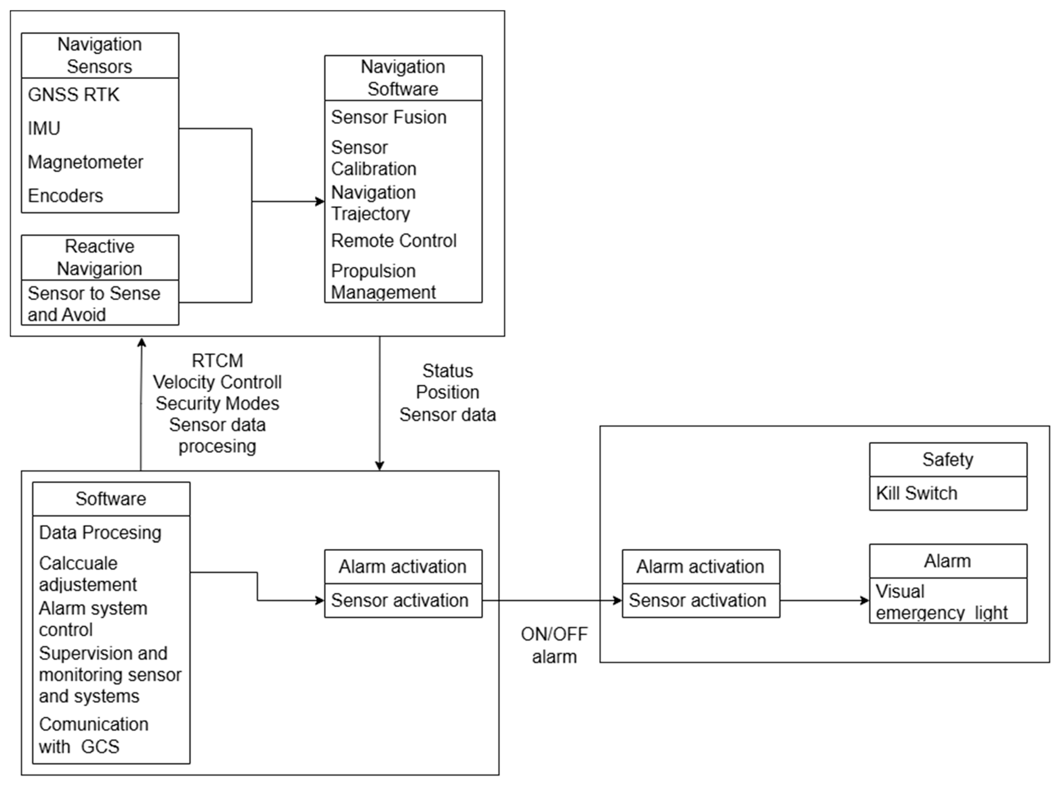
Based on these regulatory and operational requirements, the RPSC was designed with a modular architecture to ensure flexibility and compliance. The architecture is structured around three main subsystems: the autopilot, the Onboard Processing Unit (OPU), and the alarm and safety system. These components exchange data in real time using MAVLink and ROS2 protocols, supporting continuous analysis and autonomous decision-making.
Figure 1 illustrates this architecture, highlighting the data flows between subsystems.
This architecture’s modularity enables each subsystem’s independent development, testing, and updating, ensuring flexibility and scalability. The design evolves from this general vision to the detailed implementation of each component, starting with the autopilot.
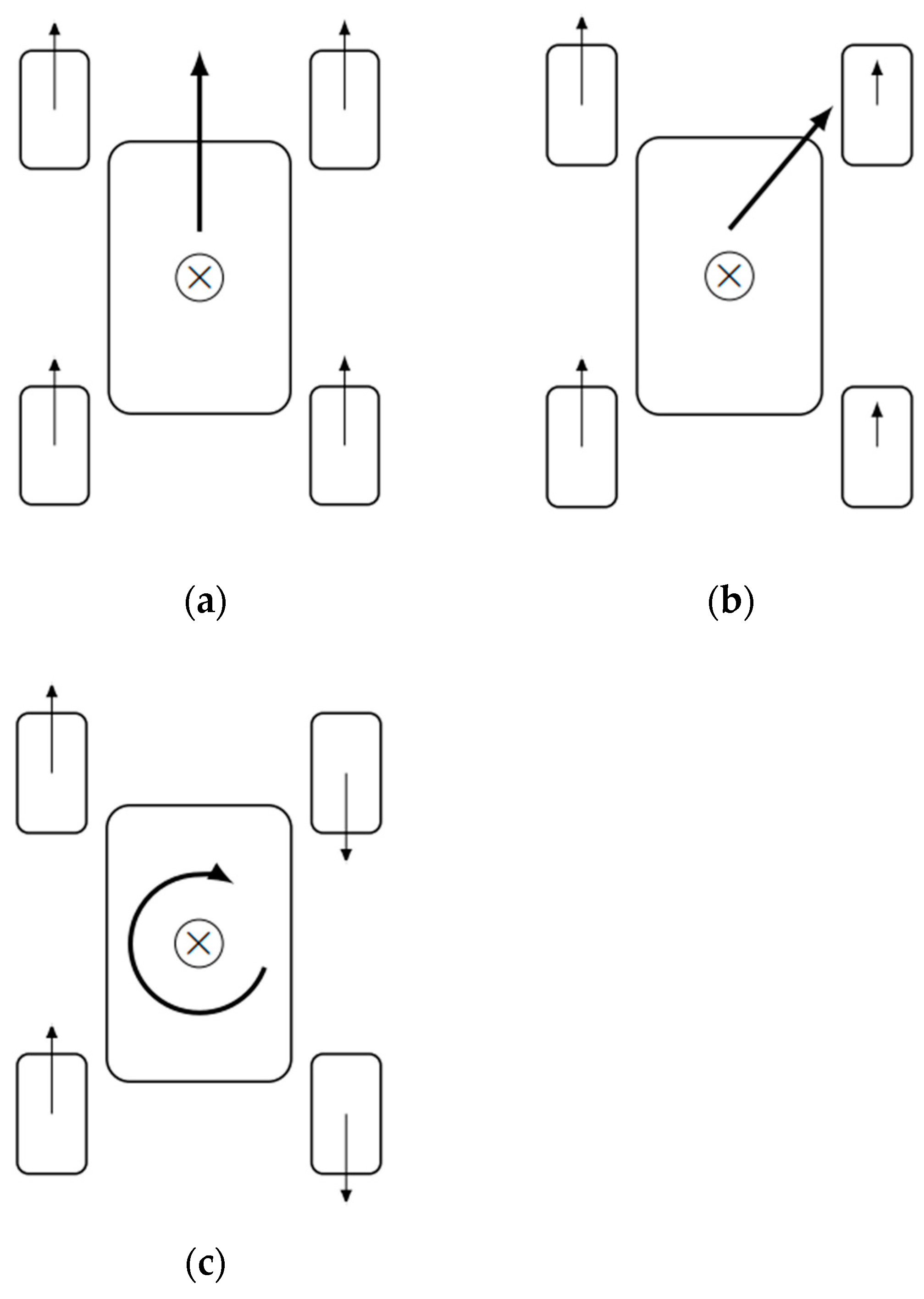
The autopilot manages the RPSC’s autonomous navigation and propulsion control. It uses a skid-steer configuration with four driven wheels. This choice optimizes maneuverability in confined spaces due to its zero-turn radius capability.
Figure 2 illustrates the possible movements with this configuration.
Figure 2a shows the rectilinear forward displacement, which occurs when the wheels on both sides rotate in the same direction and at the same speed, allowing the vehicle to move forward linearly. In
Figure 2b, a curved trajectory is observed, resulting from the wheels on one side rotating at a higher speed than those on the opposite side; this generates a difference in angular velocity and, therefore, a smooth rotation of the robot.
Figure 2c represents rotation about its own axis or in-place turning, which is achieved when the wheels on one side turn forwards and those on the opposite side turn backwards, allowing a zero turning radius and facilitating manoeuvring in confined spaces.
Autonomous navigation relies on sensors that estimate the robot’s state vector (position, orientation, and velocity) and detect its surroundings.
Table 1 describes these components and their functions.
The sensors listed in
Figure 1 are integrated to provide robust navigation capabilities. Encoders enhance odometry by measuring motor rotations, enabling accurate displacement and velocity calculations. The Inertial Measurement Unit (IMU) plays a crucial role in scenarios where GNSS signals are degraded, estimating the robot’s displacement based on accelerations along its axes. The magnetometer corrects accumulated errors in the trajectory estimation by providing orientation data relative to the Earth’s magnetic field. For reactive navigation, ultrasonic sensors detect obstacles in real time, and algorithms dynamically adjust the robot’s trajectory based on the detected obstacles. This cohesive fusion of sensors enables the RPSC to navigate predefined routes accurately and efficiently avoid obstacles.
The autopilot software must support this sensor integration, which needs to be optimised for ground vehicles. As summarised in
Table 2, the software is structured in distinct modules to ensure stability, efficiency, and adaptability. These modules process real-time data from the navigation sensors.
Building on the autopilot software’s modular framework, the OPU acts as a high-level orchestrator, ensuring cohesive system operation by processing aggregated data and managing the parameters and states of the autopilot, safety systems, and communications. The OPU interfaces with the autopilot and sensors via Universal Asynchronous Receiver/Transmitter (UART), facilitating real-time telemetry and remote configuration.
Table 3 summarises the OPU’s capabilities, highlighting its pivotal role in integrating the RPSC’s subsystems for improved safety and efficiency.
The OPU’s architecture supports a decentralized operational approach, significantly reducing latency compared to cloud-based alternatives and enabling rapid response time, an essential requirement in dynamic roadwork environments. This decentralized framework is integrated with a communication system that utilizes Wi-Fi technology. These specifications ensure continuous and reliable data exchange with control stations and other robots.
The OPU implements a dedicated safety subsystem to enhance system reliability and integrate control and safety mechanisms. In case of a failure or loss of communication, the OPU autonomously halts the RPSC and activates high-intensity visual alarms driven through General Purpose Input/Output (GPIO). These independent safety functions, complemented by an emergency kill switch that interrupts the power supply to the entire system, provide the necessary robustness to operate in high-risk environments.
2.3. Hardware Architecture
The RPSC integrates COTS hardware to minimise development time and ensure reliability, as detailed in
Table 4. The components were selected to meet the design requirements and comply with the UNE-EN 13422:2019 and UNECE standards.
The RPSC’s robotic platform was built upon the GoBilda Recon chassis, a commercial solution that offers dimensional compatibility with the base of standardised traffic cones used in Europe under the UNE-EN 13422:2019 regulation. This structure provides a stable foundation and enables the direct mechanical integration of propulsion modules, sensors, and power systems without compromising the device’s stability. This choice significantly reduces the need for custom parts, simplifies assembly logistics, and ensures component interoperability, with all elements sourced from a single supplier.
Figure 3 shows the assembled RPSC, which integrates the propulsion modules, sensors, and GNSS module on the GoBilda Recon chassis, highlighting the compact design that allows for combining a regulatory safety cone.
Figure 3a shows the RPSC’s electronic module, where the Pixhawk, Driver, and Raspberry Pi are mounted on a 3D-printed structure.
Figure 3b shows the RPSC, with all the propulsion and sensing modules integrated; the GNSS receiver is located at the top to avoid electromagnetic interference and ensure optimal satellite signal reception.
Figure 3c shows the RPSC in its final configuration, ready to be deployed in road maintenance works, incorporating a homologated signalling cone on the robotic platform to ensure compliance with current regulations.
Built upon this foundation, the RPSC’s propulsion system consists of four GoBilda Yellow Jacket 5203-series motors, goBILDA, Greenville, TX, USA, selected for their balanced speed-to-torque ratio. These motors have Hall-effect encoders, making them compatible with the autopilot’s odometry estimation requirements. They are paired with all-terrain wheels from the same manufacturer, featuring foam inserts and a high-profile design to enhance adaptability across diverse surfaces.
To manage these capabilities, the RPSC’s autopilot controller is based on the Pixhawk 2.4.8, Holybro, Shenzhen, China, an open-architecture controller widely recognised in robotics applications. Its selection is based on its support for multiple sensors and its ability to generate Pulse Width Modulation (PWM) signals for motor control. The Pixhawk contains internal sensors, including an accelerometer, gyroscope, and magnetometer. It also allows the integration of external modules via UART, Inter-Integrated Circuit (I2C), Controller Area Network (CAN), and Serial Peripheral Interface (SPI) interfaces. This versatility enables the connection of encoders and proximity sensors, fulfilling the system’s autonomous navigation requirements.
In turn, the RPSC’s positioning is provided by the Here3+ GNSS module, CubePilot, Taipei, Taiwan, which incorporates RTK corrections to achieve high accuracy. This module offers redundancy through an independent IMU and magnetometer. Its capability to operate with multiple satellite constellations (Global Positioning System (GPS), Global’naya Navigatsionnaya Sputnikovaya Sistema (GLONASS), Galileo, and BeiDou) ensures constant signal availability, even in partially obstructed areas, making it ideal for road work environments.
The OPU, implemented with a Raspberry Pi 5, Raspberry Pi Ltd., Cambridge, UK, serves as the RPSC’s logical core. Its quad-core ARM Cortex-A76, ARM Ltd., Cambridge, UK, architecture provides the computational capacity to run ROS2, manage additional sensors, interface with the Pixhawk via MAVROS, and transmit data to remote stations over Wi-Fi. It is equipped with an Alfa AWUS036ACH, Alfa Network, Taipei, Taiwan, dual-band (2.4/5 GHz) adapter to enhance this wireless connectivity, offering greater range and stability than the built-in Wi-Fi module.
2.3.1. Communications Architecture
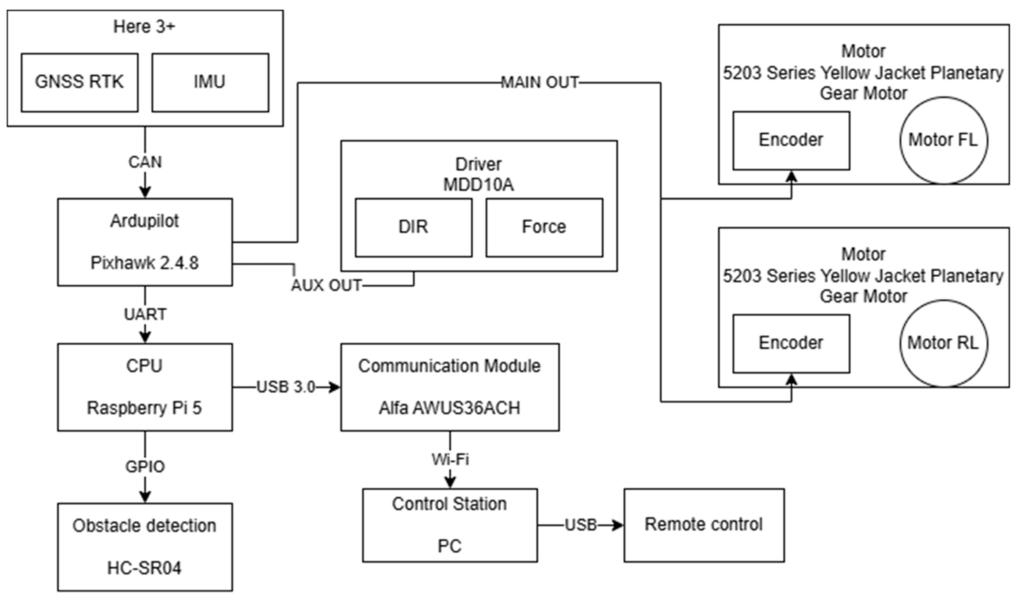
The communications architecture of the RPSC has been designed to guarantee efficient integration between its components. The correct allocation of ports and communication protocols minimises delays in critical processes, optimising the stability and security of the system. The interconnection of the elements was organised according to their operational needs, prioritising those processes that require minimum latency, such as navigation and odometry, over others that are less critical (
Figure 4).
The RPSC motors are connected in parallel to the MDD10A controller, Cytron Technologies, Penang, Malaysia, enabling efficient power distribution without compromising the system’s differential control. To optimize the connection, the motors on the right-hand side share a positive and negative terminal with channel A of the driver. In contrast, the motors on the left-hand side share a positive and negative terminal with channel B.
The Pixhawk 2.4.8 generates the PWM speed control signals sent via the AUX OUT pins. The motor direction signals are transmitted via the MAIN OUT pins. The left and right front motor encoders are also directly connected to the Pixhawk’s AUX OUT pins, accurately estimating the robot’s displacement.
The RPSC’s navigation system relies heavily on the Here3+ positioning module. This module is connected to the Pixhawk via the CAN interface, enabling stable and low-latency data transmission.
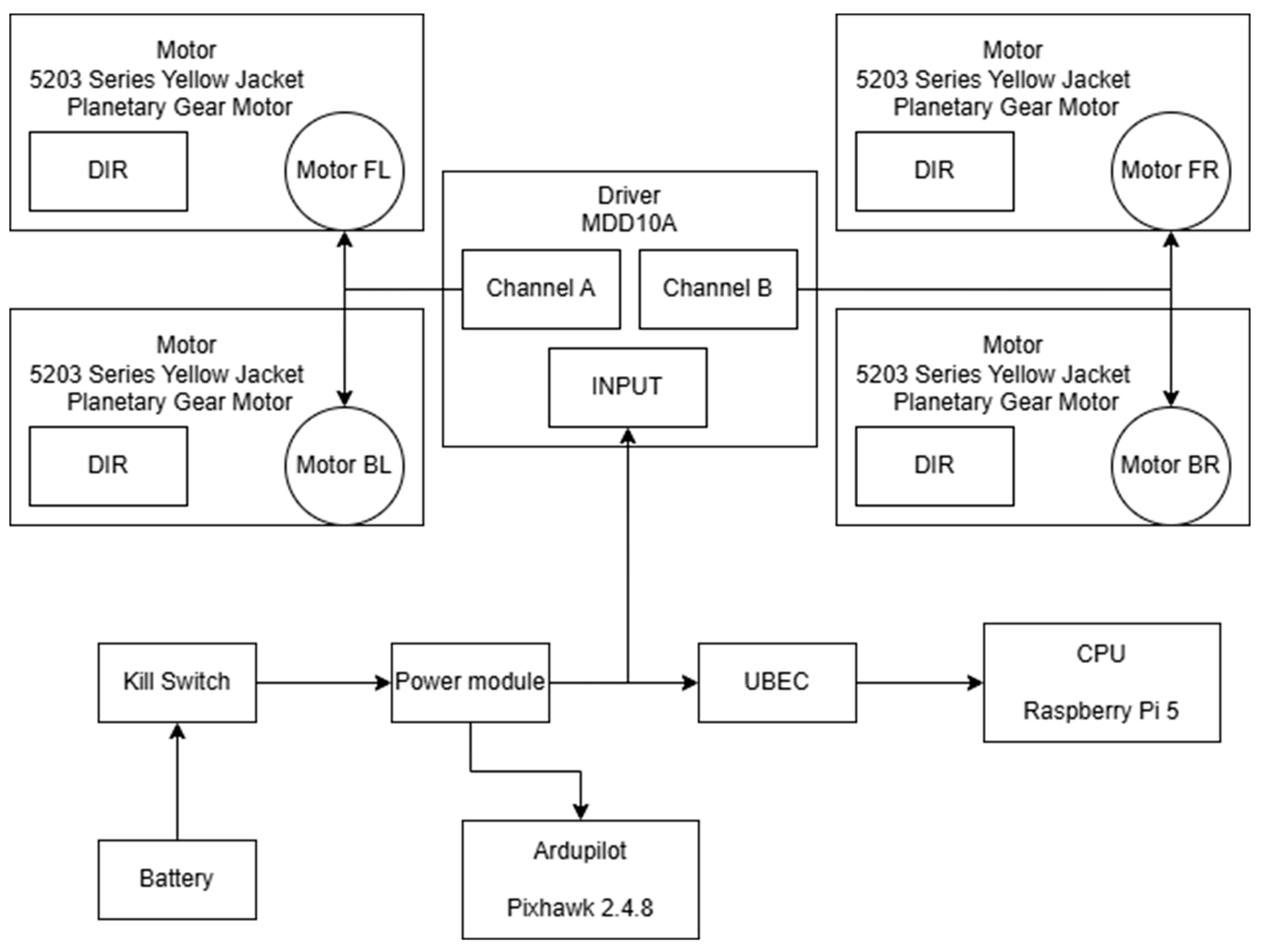
2.3.2. Power System Architecture
The RPSC power system was designed with a priority-based distribution scheme to ensure a stable voltage supply to the autopilot. By placing the Pixhawk power module at the first stage of the circuit, it receives the cleanest possible voltage, even during transient drops caused by high current demands from the motors (
Figure 5).
The system is powered by an 11.1V LiPo battery (3s1p), serving as the primary energy source. A kill switch ensures safety by instantly cutting power to all components in an emergency or during maintenance. The Pixhawk Power Module regulates the battery voltage, delivering a stable 5.1 V to the Pixhawk while monitoring power consumption. The system distributes power efficiently through parallel bifurcation: a Universal Battery Eliminator Circuit (UBEC) regulator steps down the voltage to 5 V, supplying the Raspberry Pi and alarm system. At the same time, the Motor Driver Power Supply directly utilises the 11.1 V to drive the RPSC motors, ensuring reliable operation of all components.
2.3.3. Autopilot Software
The software used in the Pixhawk platform is based on ArduRover firmware, an open-source solution within the ArduPilot ecosystem specifically developed for autonomous ground vehicles. This solution enables essential tasks, including autonomous navigation, propulsion control, and sensor management. It also supports real-time sensor fusion and LUA script development inside the controller. It also features direct integration with the ROS2 framework through MAVROS, which encodes MAVLink messages within the ROS2 environment. This enables the Pixhawk software to facilitate customised and adaptive operation according to the vehicle’s specific requirements.
Accurate state estimation is essential for the RPSC’s autonomous navigation capabilities. To this end, the software utilises an extended Kalman filter (EKF) to integrate and fuse signals from the GNSS RTK system, IMU, encoders, and magnetometer in real-time. This fusion enables the continuous estimation of the robot’s state vector, mitigating the cumulative errors of the odometry and ensuring stability, even in conditions of GNSS signal degradation. For the RPSC, which operates in dynamic environments with active traffic, the EKF is particularly important as interference or partial loss of the satellite signal is common. The software dynamically adjusts the weight given to each sensor according to its accuracy and integrity, enabling the EKF to optimise navigation performance continuously.
The EKF is configured to use the Pixhawk’s built-in barometer as the primary source of altitude information. Wheel encoders estimate horizontal velocity and provide direct displacement data. The Here3+’s magnetometer determines orientation. Conversely, the GNSS RTK is the primary source for global positioning, delivering centimetre accuracy.
In RPSC control, the software independently controls each side of the vehicle using PWM signals, steering, and differential traction. The system utilizes cascaded PID controllers, specifically velocity and position PID controllers, to regulate linear velocity and yaw, while a separate PID controller adjusts angular steerability. Linear acceleration ramps are also implemented in the software to ensure smooth transitions in velocity. This limits the derivative of the PWM signal, reducing mechanical stress on the motors. These ramps are configured with adjustable incremental rates according to the terrain’s demands.
Operational safety is a fundamental aspect of the RPSC design, achieved through a series of fail-safe mechanisms programmed to stop the system in the event of an anomaly. These mechanisms are configured to activate in critical conditions, such as loss of connection, sensor failure, or interruption to the control link, ensuring that the vehicle stops safely. The first fail-safe is a pre-check of sensor activation, battery status, and communication links. It verifies that the minimum number of required GNSS satellites is available to ensure reliable navigation. Loss of communication with the ground control station triggers another fail-safe, switching the RPSC to HOLD mode. Similarly, a Lua script monitors the connection between the Pixhawk and the Raspberry Pi by checking for a heartbeat signal every 0.5 s. If the heartbeat signal is absent, indicating a loss of communication, the script forces the vehicle into HOLD mode and disarms it.
The ArduPilot ecosystem is complemented by Mission Planner software, which acts as a ground control station (GCS) and operational extension of the autopilot. Mission Planner provides an interface for monitoring, parameterisation, and remote control of the RPSC, allowing a physical controller to be connected to the station and thus facilitating manual operation when necessary. The Pixhawk, running ArduRover, communicates with a Raspberry Pi running MAVROS within the ROS2 environment. MAVROS is responsible for establishing a bidirectional UDP link with Mission Planner using the MAVLink protocol, enabling real-time transmission of telemetry, commands, and mode of operation changes.
2.4. Software Architecture
The Raspberry Pi runs Ubuntu Server 24.04 and ROS2 Jazzy. By using the server version, the graphical interface is removed, dedicating processing capacity to essential algorithms for the RPSC. ROS2 Jazzy provides a modular framework for efficient node management, ensuring interoperability among the RPSC subsystems. The architecture is based on distributed ROS2 nodes, ensuring scalability and robustness. The key nodes are as follows:
MAVROS Node: As the primary interface between ROS2 and the Pixhawk, utilising the MAVLink v2 protocol via the serial port /dev/ttyS0, configured at 57,600 bps. It handles critical data, publishing topics such as /RPSC/local_position/pose for local pose, /RPSC/global_position/global for global GNSS position, and /RPSC/state for system status, while subscribing to /RPSC/setpoint_velocity/cmd_vel to send velocity commands. This node ensures smooth, bidirectional communication, integrating the Pixhawk with the ROS2 ecosystem.
Visual Alarm Node: This node controls relays connected to the Raspberry Pi’s GPIO pins to activate high-intensity visual signals in critical situations. It receives commands from the control station or the Pixhawk via the /RPSC/visual_alarm_cmd topic, triggering immediate alerts to warn workers and road users. This node operates with high priority to guarantee a rapid response.
Obstacle Detection Node: This node processes data from the HC-SR04 ultrasonic sensor connected to the Raspberry Pi, generating local obstacle maps in LaserScan format and publishing them on /RPSC/obstacle_scan. This data is converted to DISTANCE_SENSOR messages using pymavlink and sent to the Pixhawk via MAVROS. This node enables the Pixhawk to dynamically adjust paths, integrating with the reactive navigation system.
RTK Injector Node: This node functions as an NTRIP client, receiving real-time RTCM corrections from an RTK base station. It processes these corrections and sends them to the Pixhawk via the /RPSC/send_rtcm topic, improving the Here3+’s GNSS positioning accuracy. This node ensures that the RPSC maintains centimetre-level accuracy, which is crucial for navigating constrained road environments.
Heartbeat Node: This node monitors communication with the control station, checking the heartbeat every 0.5 s. If a disruption is detected, it triggers an emergency protocol that sends a command to the /RPSC/set_mode topic to switch to HOLD mode, disarms the motors, and activates the visual alarms via the corresponding node. This node complements Pixhawk’s LUA script, providing an additional safety layer.
Autonomous Motion Node: This node receives velocity information via the /RPSC/setpoint_velocity/cmd_vel topic, which contains linear and angular velocities. The Pixhawk receives these commands and adjusts its route to match the specified speed. It can also recalculate its route if the obstacle detection node detects an object in the RPSC’s path.
Wi-Fi Mapping Node: This node uses the Wi-Fi module to log the real-time quality of Wi-Fi coverage. It processes data from /RPSC/global_position/global and /RPSC/gps_status topics (Horizontal Dilution of Precision (HDOP) and Vertical Dilution of Precision (VDOP)), generating logs that include global position, altitude, and Wi-Fi signal quality. The data are stored as ROS2 bags for later analysis, allowing evaluation of communication quality during RPSC operations.
RPSC Lifecycle
The RPSC lifecycle is implemented as an ROS2 node called rpsc_lifecycle_node. Unlike previous nodes that added specific functionalities, this node is responsible for managing the operational states of the system and coordinating transitions between them. The lifecycle includes the following states: INITIALIZING, WAITING RTK, INITIALIZED, FOLLOWING, MANUAL, and ALERTING. Transitions between these states are based on initialisation conditions, GNSS quality, mode commands, and failsafe or alarm events. The state machine, which is designed to coordinate the safe operation of the RPSC and outline its functionality, is presented in the pseudocode below (Algorithm 1).
| Algorithm 1: Pseudocode for RPSC state machine |
STATE = INITIALIZING
while system_active:
if STATE == INITIALIZING:
enforce DISARM and HOLD modes
if verify_sensors_connection() and validate_RPi_Pixhawk_link() and confirm_control_station_heartbeat():
STATE = WAITING_RTK
elif STATE == WAITING_RTK:
enforce DISARM and HOLD modes
if verify_RTK_correction_quality() and evaluate_HDOP_VDOP_metrics() and confirm_positioning_stability():
STATE = INITIALIZED
elif STATE == INITIALIZED:
execute_arming_procedure()
set operational mode to HOLD
if manual_operation_command_received():
STATE = MANUAL
set operational mode to MANUAL
elif autonomous_operation_command_received():
STATE = FOLLOWING
set operational mode to GUIDED
elif STATE == MANUAL:
process_manual_input_signals()
issue_velocity_commands_to_MAVROS()
if anomaly_detected():
enforce DISARM and HOLD modes
STATE = INITIALIZING
elif STATE == FOLLOWING:
execute_autonomous_navigation_commands()
issue_velocity_commands_to_MAVROS()
if anomaly_detected():
enforce DISARM and HOLD modes
STATE = INITIALIZING
elif STATE == ALERTING:
enforce DISARM and HOLD modes
if alarm_condition_cleared():
STATE = INITIALIZING
if alarm_condition_received():
STATE = ALERTING
enforce DISARM and HOLD modes |
3. Results
This section presents the experimental results obtained from field tests of the RPSC prototypes. The analyses are structured around three key performance areas: GNSS positioning accuracy using RTK corrections from different vendors, trajectory tracking accuracy under various sensor configurations, and the effectiveness of the obstacle detection system. Each sub-section provides a detailed assessment of the corresponding system component, supported by quantitative metrics, graphs, and comparative insights, enabling an evaluation of RPSC performance.
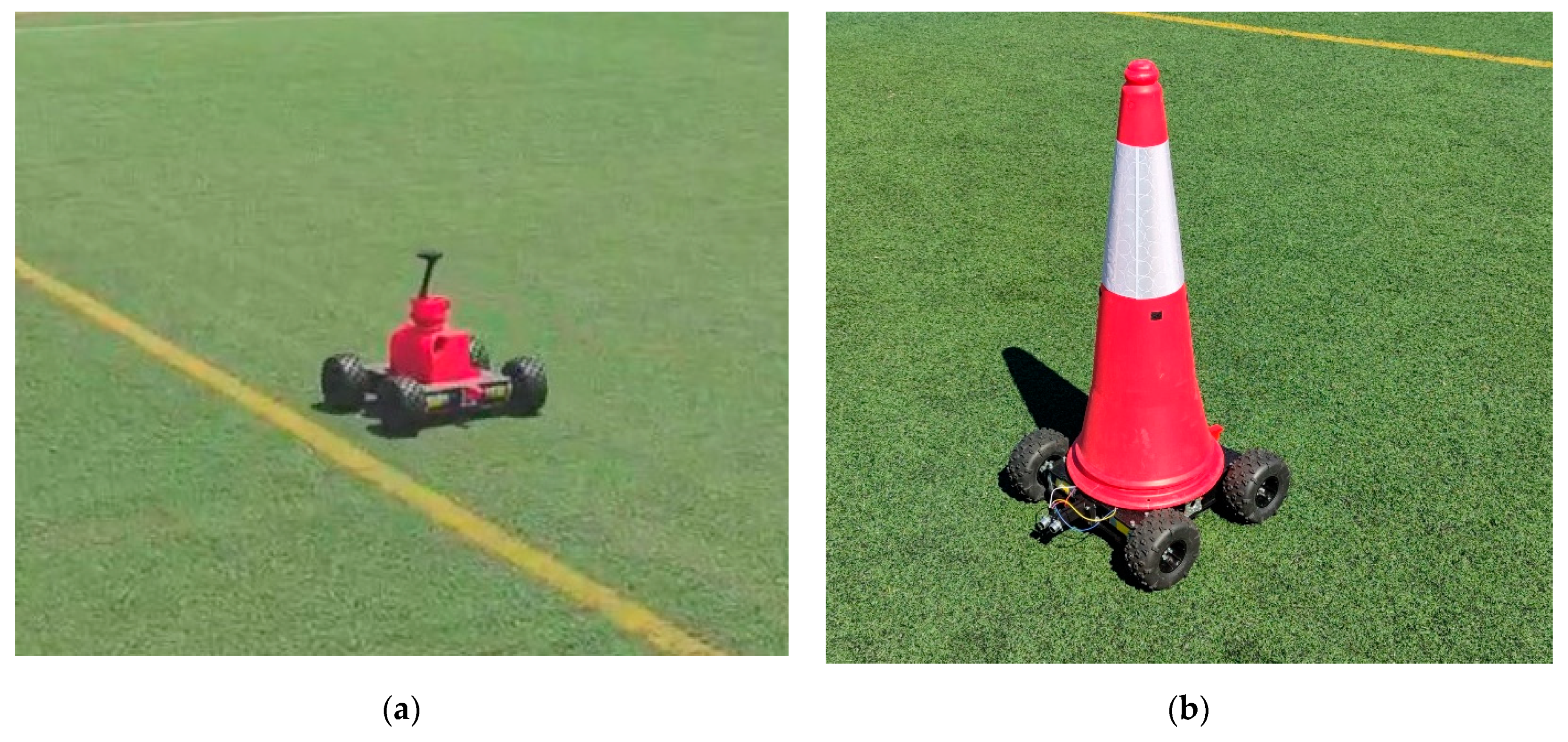
Figure 6a shows an RPSC used for testing navigation and motion control algorithms. This platform was a development unit for fine-tuning sensor integration and movement commands.
Figure 6b shows an RPSC with a traffic cone mounted on the mobile base, performing positioning tests under real conditions.
3.1. Use Case
A case study that evaluates the performance and accuracy of the RPSC in three critical areas: positioning, navigation, and obstacle detection is presented. The tests were conducted at the As Lagoas Campus of the University of Vigo, located in Galicia, northwestern Spain—a controlled environment. Each test was designed to analyze specific aspects of the RPSC’s behaviour, providing key insights to enhance its operational capabilities.
Rosbag was used to collect data for the three case studies. It enabled recording data published on system topics, including telemetry, navigation, and vehicle status.
3.1.1. Positioning
This test aimed to evaluate the RPSC’s positioning accuracy and determine the GNSS error, thereby establishing a baseline for navigation reliability. Ground Control Points (GCPs) were previously measured and georeferenced with the Trimble R8 GNSS system. The RPSC, calibrated to receive RTK corrections, was positioned at these points. The positioning error was calculated by comparing the position reported by the Here3+ GNSS with the known location of the GCPs.
Multiple RTK correction services were used to optimise accuracy: the Instituto Geográfico Nacional (IGN) GNSS network, which provides high-precision positioning across Spain, and Hexagon’s SmartNet, a global high-precision network. The tests were repeated with each service to ensure consistency in the results.
3.1.2. Navigation
This test assessed the route deviation of the RPSC during autonomous operations, analysing the precision and stability of its navigation. A route was defined using waypoints based on GCPs. The RPSC was deployed to follow this route under different sensor configurations to evaluate their impact on navigation accuracy. The tested configurations are shown in
Table 5.
Configuration 3 utilised RTK corrections from the positioning service, which achieved the best metrics in the positioning test.
3.1.3. Obstacle Detection
This test analyzed the RPSC’s ability to detect and respond to obstacles using the HC-SR04 ultrasonic sensor. Markers were placed on the ground at known distances from 20 to 200 cm, and cardboard prisms were used as obstacles. Their positions varied systematically while the RPSC remained stationary.
3.2. Positioning
This test analyses GNSS positioning performance with RTK using two different providers, IGN and Smartnet, evaluated on two RPSCs located on two GCPs, respectively. The primary objective is to characterise the positioning system’s convergence, stability, and precision behaviour under real-world conditions, focusing on the quality of the solution after acquiring the RTK fix, the consistency of the horizontal error, and the system’s sensitivity to disturbances.
Table 6 shows the results of the tests performed.
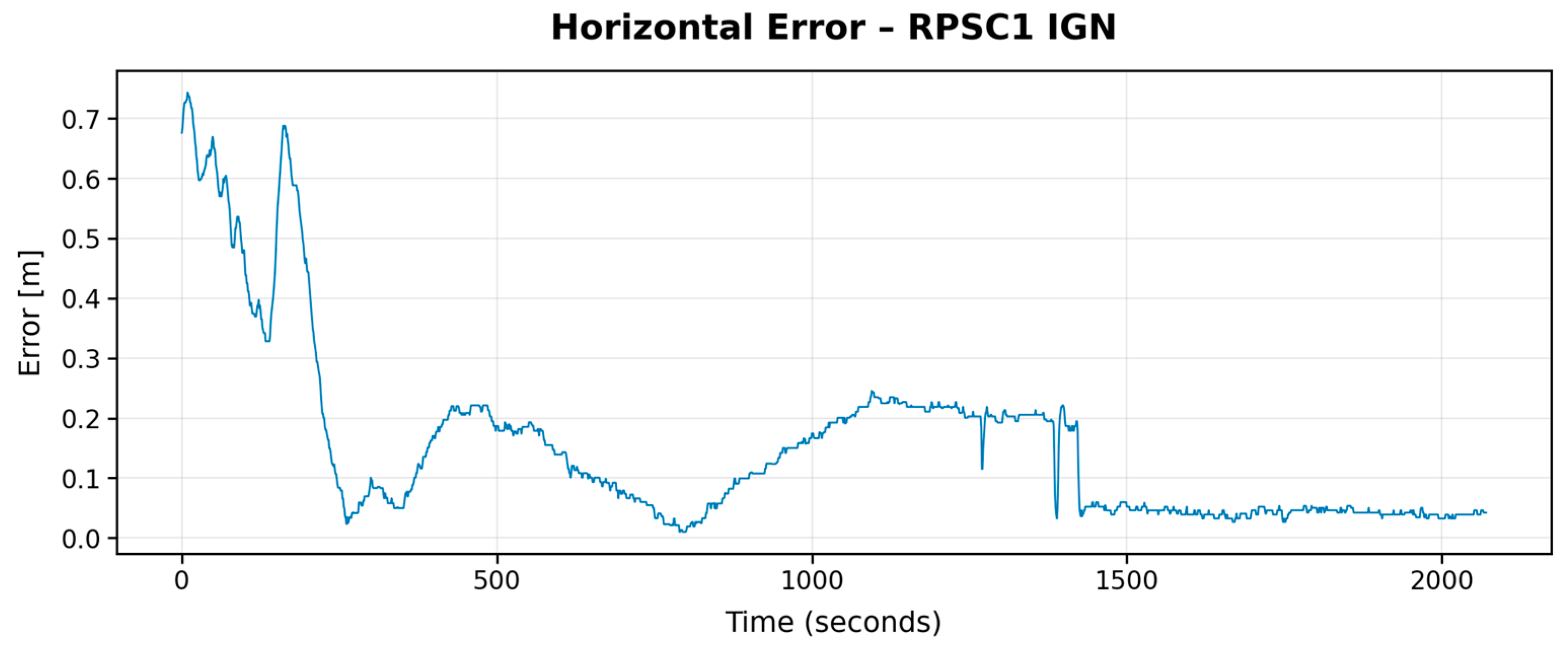
The convergence of the positioning solution was measured as the number of samples required to reach a stable error zone below the 95
th percentile. In this aspect, marked differences are evident between the two evaluated services. In the case of RPSC1 with the IGN service (
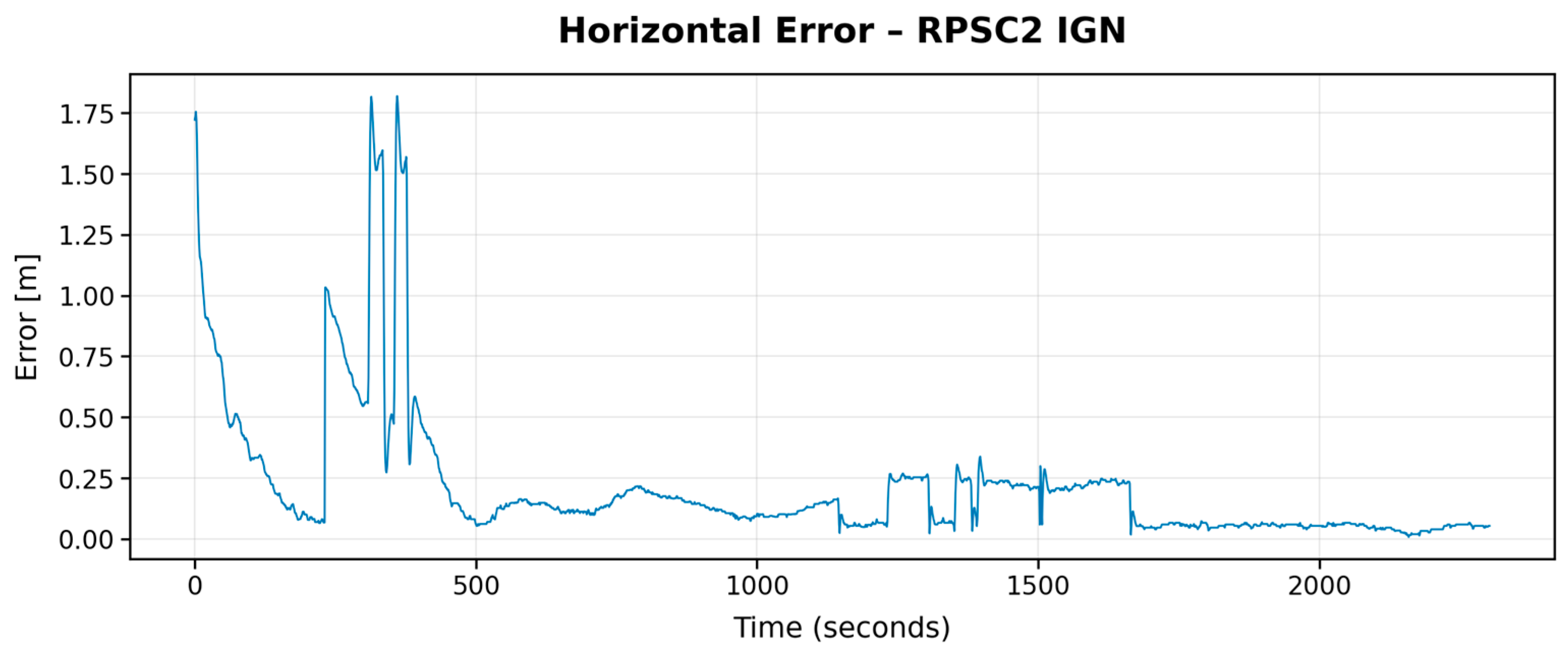
Figure 7), 1824 samples were required to stabilise the signal, while RPSC2 (
Figure 8) needed 2045 samples with the same service, representing more than 88% of the total in both experiments. This slow convergence indicates that the GNSS system operating with IGN presents a prolonged transition before reaching a reliable RTK solution. In contrast, with the SmartNet service, both RPSC1(
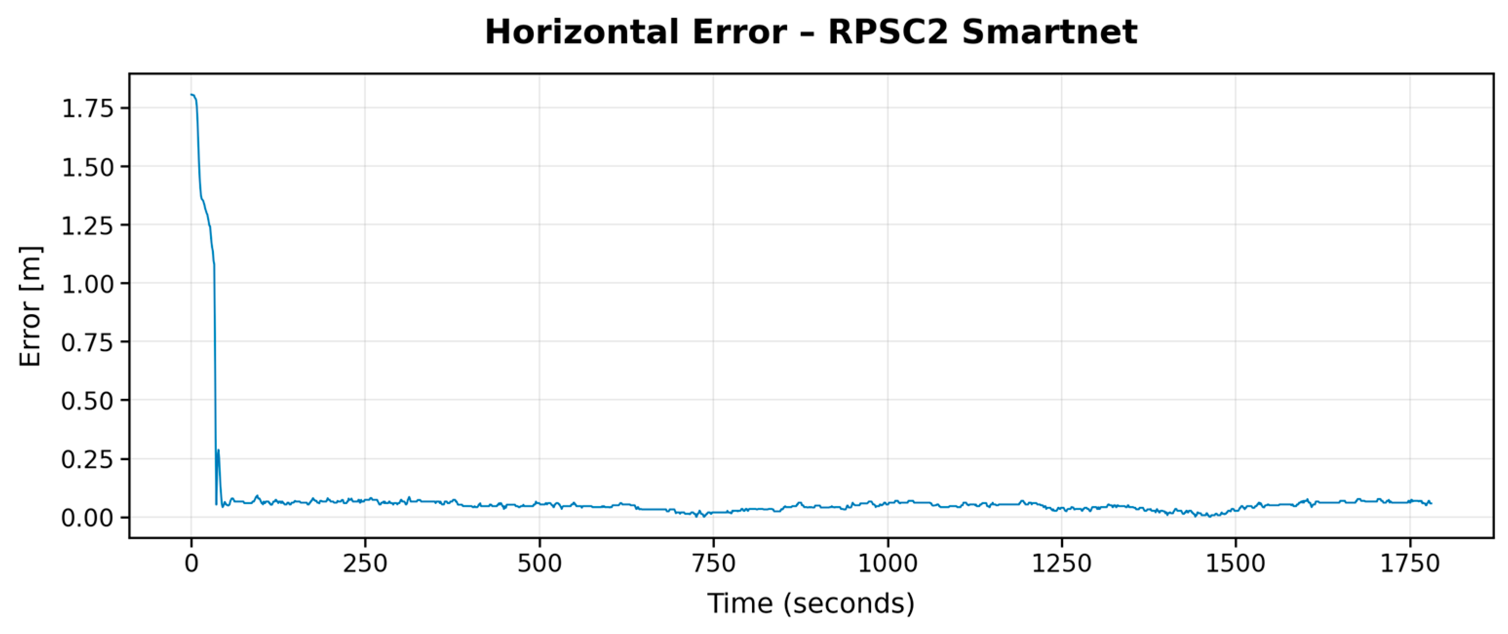
Figure 9) and RPSC2 (
Figure 10) stabilised in around 1539 samples, showing a more efficient and consistent fix acquisition process. This improvement can be attributed to a higher frequency of correction transmission, lower latency in the Networked Transport of RTCM via Internet Protocol (NTRIP) network, or a denser base station infrastructure, all of which are crucial factors for dynamic robotic applications that require a high-precision solution in a short timeframe.
The stability of the RTK solution was analyzed in terms of temporal variability, presence of jitter, and occurrence of error peaks that could indicate loss of fix. In the temporal graphs of the horizontal error, it is observed that RPSC2 with IGN exhibits multiple discontinuities, with errors exceeding 1 m, suggesting sporadic losses of the fixed solution or temporary degradations in the correction quality. These losses could be related to environmental factors or insufficient GNSS coverage during specific intervals. In contrast, the error profiles associated with SmartNet, both in RPSC1 and RPSC2, show an abrupt drop in error followed by a stable plateau, without significant oscillations or evident jumps, which confirms greater robustness against external disturbances and better quality of filtering or interpolation of RTK corrections.
From a quantitative perspective, the numerical results allow for a clear comparison between the different configurations. The mean error for RPSC1 with SmartNet was 0.114 m, with a standard deviation of 0.181 m and an RMSE of 0.214 m. In contrast, the worst performance was recorded with RPSC2 using IGN, with a mean error of 0.212 m, a standard deviation of 0.285 m, and an RMSE of 0.355 m. The relationship between the standard deviation and the mean value (coefficient of variation) also supports these observations: while IGN showed more consistent values in RPSC1 (CV = 0.98), this relationship degrades in RPSC2 (CV = 1.34), reflecting greater instability. Although SmartNet presents a higher CV in RPSC1 (1.59), this high value is a direct consequence of a small denominator (low mean error), which does not imply worse absolute stability. These results confirm that the SmartNet service offers more precise solutions globally and is less prone to extreme errors.
In the context of this test, SmartNet has demonstrated a greater ability to maintain a fixed and precise RTK solution over time, while IGN appears more susceptible to fluctuations in link quality or satellite geometry. In all cases, a typical pattern of error evolution is observed, consisting of an initial acquisition phase, a transition towards stabilisation, and a subsequent low-error phase. However, the duration and regularity of these phases strongly depend on the service used.
In conclusion, this test demonstrates that utilising the SmartNet service provides significant advantages in terms of precision, temporal stability, and convergence time for GNSS+RTK systems on mobile robotic platforms. In scenarios where precise, real-time positioning is required, such as autonomous tracking, assisted navigation, or swarm formation, these improvements can directly translate into greater operational safety and efficiency.
3.3. Navigation
The following is a series of tests designed to evaluate different sensor configurations on the trajectory tracking accuracy of RPSCs. Three consecutive trials were conducted to analyze the system’s performance without sensors, with only encoders, and finally with encoders and RTK combined. Each configuration allowed for observing how the performance of the RPSC varies in terms of deviation from the planned path, providing information on each sensor’s relative and complementary importance in real environments.
In the first test, the RPSC operated without both RTK and encoders. In this configuration, an average deviation distance of 0.45 m and a standard deviation of 0.42 m were observed. The maximum deviation reached 1.75 m.
Without the encoders, the RPSC lacks continuous feedback on its wheel movement, and the absence of RTK means it also does not receive precise absolute position corrections, as shown in
Figure 11. In the top subfigure, the yellow segment represents the predefined path for the RPSCs to follow, while the red segment shows the actual travelled route. This results in the RPSC navigating based on less accurate data, leading to larger and more variable deviations. The combined absence of both sensor types significantly compromises the RPSC’s ability to maintain its planned route, as it lacks both the real-time correction capability of the encoders and the high-precision absolute correction provided by RTK.
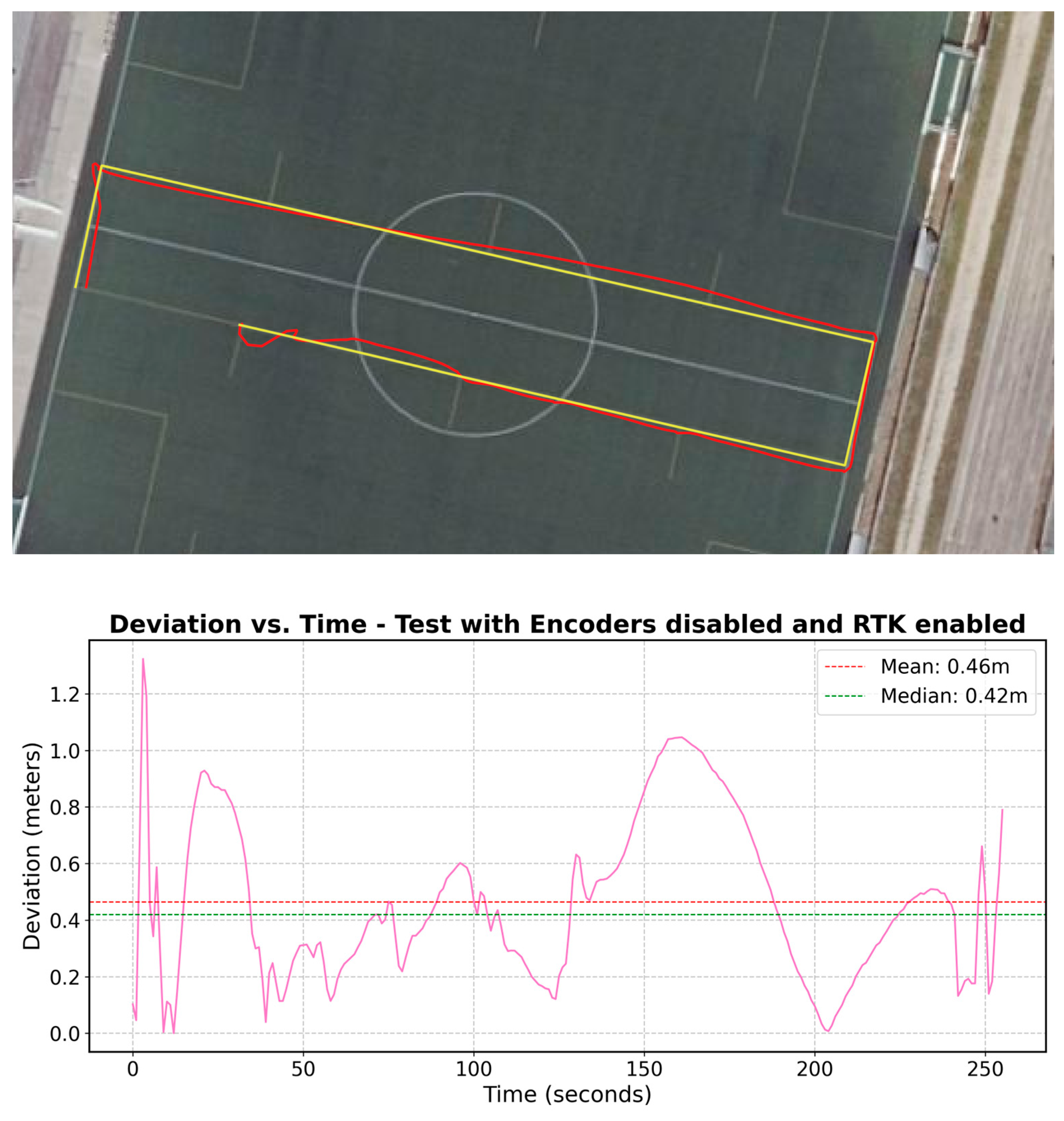
In the second test, the RPSC used encoders but did not have RTK support (
Figure 12). The results showed an average deviation distance of 0.46 m and a standard deviation of 0.28 m. The maximum deviation was 1.32 m.
Without the absolute correction RTK provides, the RPSC is forced to rely solely on encoders, which only provide relative information about movement. This data type can accumulate errors over time, known as drift. These accumulated errors manifest as larger deviations in the RPSC’s route without an external correction source. Although the encoders help maintain consistency in the trajectory, the lack of absolute precision from RTK leads to significant deviations.
The RPSC was equipped with both encoders and RTK from SmartNet in the third test. The results shown in
Figure 13 illustrate an average deviation distance of 0.20 m, with a standard deviation of 0.14 m. The maximum recorded deviation was 0.75 m.
This configuration, which combines encoders and RTK, offers the highest accuracy in positioning the RPSC. Encoders play a crucial role in maintaining control of the RPSC’s movement by providing real-time feedback on its displacement. This information allows the RPSC to continuously adjust its trajectory and correct minor deviations immediately. On the other hand, RTK provides highly accurate absolute position correction. Integrating these two sensor types results in a robust and reliable system that minimises deviations, ensuring the RPSC stays as close to its planned route.
When comparing the navigation tests, the combination of encoders and RTK offers the best route accuracy.
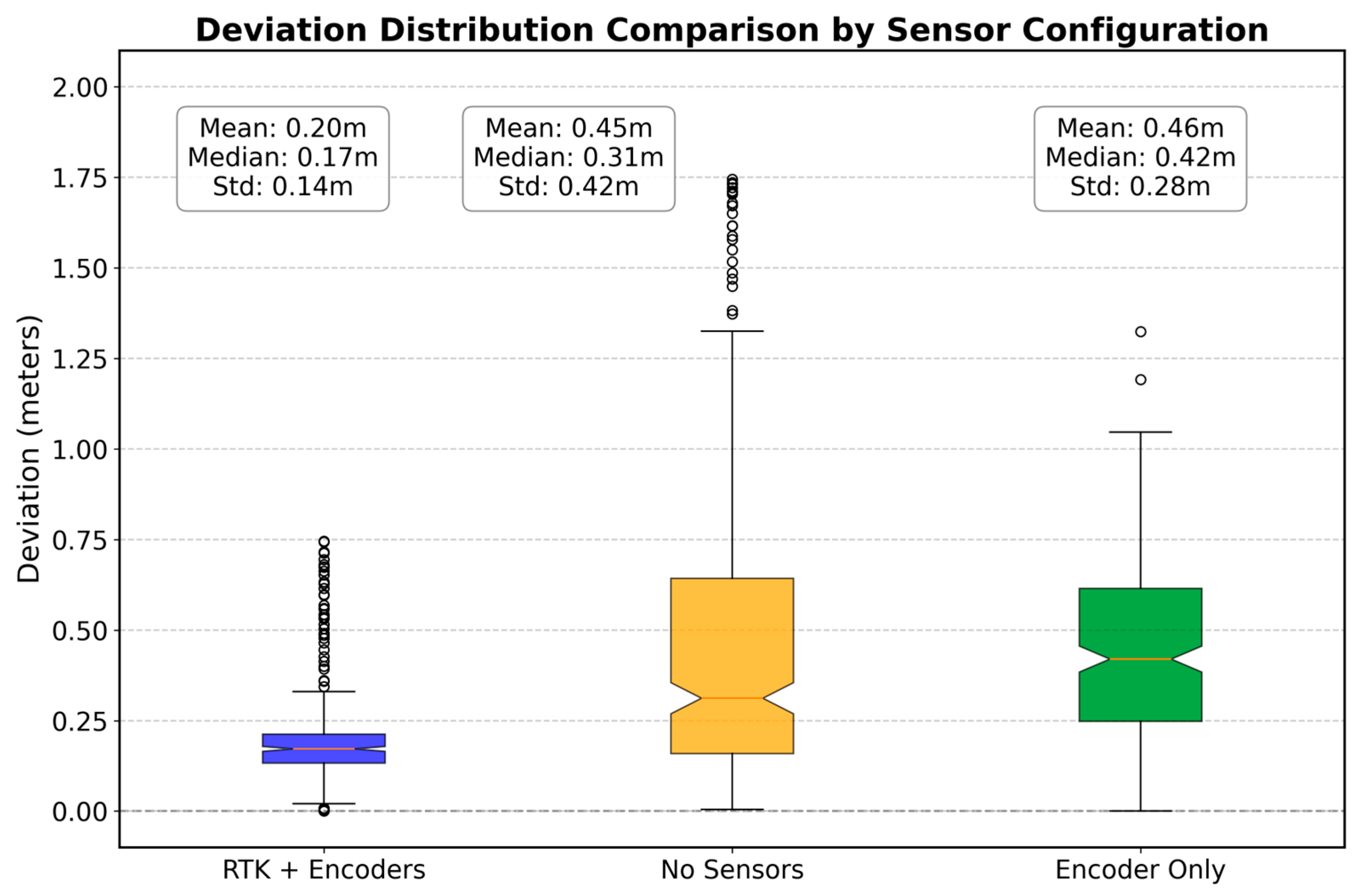
Table 7, showing the statistical data for the different sensor configurations, highlights the differences between the tests.
Measures of central tendency indicate that the RTK + Encoders configuration has the lowest mean (0.20 m) and median (0.17 m), suggesting high accuracy and consistency. In contrast, the No Sensors configuration shows a mean of 0.45 m and a median of 0.31 m, evidencing a significant increase in localisation uncertainty. The Encoders Only configuration presents a mean of 0.46 m and a median of 0.42 m, reflecting intermediate performance but still less accurate than the combination of RTK and encoders.
In terms of variability,
Figure 14 shows significantly less dispersion in the RTK + Encoders configuration, with a standard deviation of 0.14 m and few outliers. This contrasts with the No Sensors configuration, which exhibits wide dispersion and multiple outliers, reaching a maximum of 1.75 m, with a standard deviation of 0.42 m. The Encoders Only configuration also exhibits some dispersion, with outliers reaching up to 1.32 m and a standard deviation of 0.28 m. This indicates that although encoders improve accuracy compared to the total absence of sensors, they still introduce some variability.
The agreement between
Figure 14 and
Table 7 confirms that the RTK + Encoders configuration is optimal for tasks requiring high accuracy in trajectory tracking, particularly in the context of RPSCs designed for road construction projects. Sensor integration enables the correction of residual errors and maintains consistency under conditions typical of roadwork environments, where environmental disturbances and irregular movement can significantly impact accuracy.
To support this claim with robust statistical evidence, a comprehensive hypothesis testing analysis was conducted, as shown in
Table 8. First, the normality of the distributions was evaluated using the Shapiro–Wilk test. The results indicated that none of the assessed configurations followed a normal distribution (W = 0.7750 for RTK + Encoders, W = 0.9522 for Encoders Only, and W = 0.8165 for No Sensors, all with
p < 0.000001). This deviation from normality rules out the use of parametric methods such as ANOVA, due to the non-Gaussian nature of the data. The lack of normality can be attributed to outliers and skewed distributions caused by real-world testing conditions.
Subsequently, Levene’s test was applied to assess the homogeneity of variances across groups. The results (W = 79.7068, p < 0.000001) indicated significant differences in data dispersion between the configurations. Since neither normality nor homogeneity of variances was satisfied, non-parametric tests were used. The Kruskal–Wallis test, appropriate under these conditions, revealed significant differences between the medians of the three configurations (H = 166.45, p < 0.000001), confirming that at least one configuration performs differently from the others.
To precisely identify these differences, pairwise comparisons were conducted using the Mann–Whitney U test, with Bonferroni correction applied to control for multiple comparisons. The results were as follows:
RTK + Encoders vs. No Sensors: U = 32,807, adjusted p < 0.000001;
RTK + Encoders vs. Encoders Only: U = 17,023, adjusted p < 0.000001;
Encoders Only vs. No Sensors: U = 34,401, adjusted p = 0.013.
These results indicate that the RTK + Encoders configuration delivers significantly superior performance. Moreover, while the Encoders Only setup slightly improves the No Sensors configuration, the difference is also statistically significant, albeit smaller. This suggests that relying solely on encoders without RTK is insufficient for reliable tracking in unstructured environments.
3.4. Obstacle Detection
In this test, an RPSC equipped with an ultrasonic HC-SR04 sensor was placed two meters away from a wall and moved slowly towards it. Distance measurements were taken using three methods: raw measurement, which corresponds to unprocessed data; moving average filtering, which involves averaging a set of measurements; and Kalman filtering, an advanced statistical filter that provides more precise estimates.
The moving average filtering method,
Figure 15, involves calculating the average of the last five measurements to reduce the noise in the original data. In the test, moving average filtering significantly improved compared to raw measurement. The mean deviation was reduced from 0.023 m in the raw measurement to 0.015 m, indicating greater accuracy. The standard deviation decreased from 0.025 m to 0.0196 m, suggesting reduced variability and noise in the measurements. The maximum and minimum deviations were also reduced, from 0.075 m and 0.002 m in the raw measurement to 0.065 m and 0.001 m, respectively, using moving average filtering. While these improvements are significant, moving average filtering does not achieve the same accuracy and stability as the Kalman filter.
The Kalman filter,
Figure 16, is an advanced statistical method that provides more precise estimates by considering both measurements and their associated uncertainty. In the test, Kalman filtering proved the most effective technique for obtaining accurate and stable distance measurements. The mean deviation was the lowest among the three methods, at 0.012 m, indicating high accuracy. The standard deviation was also the lowest, at 0.015 m, suggesting less variability and noise in the measurements. Furthermore, the maximum and minimum deviations were reduced to 0.050 m and 0.001 m, respectively, evidencing high consistency in the obtained data. These characteristics make the Kalman filter ideal for applications requiring high precision and measurement stability.
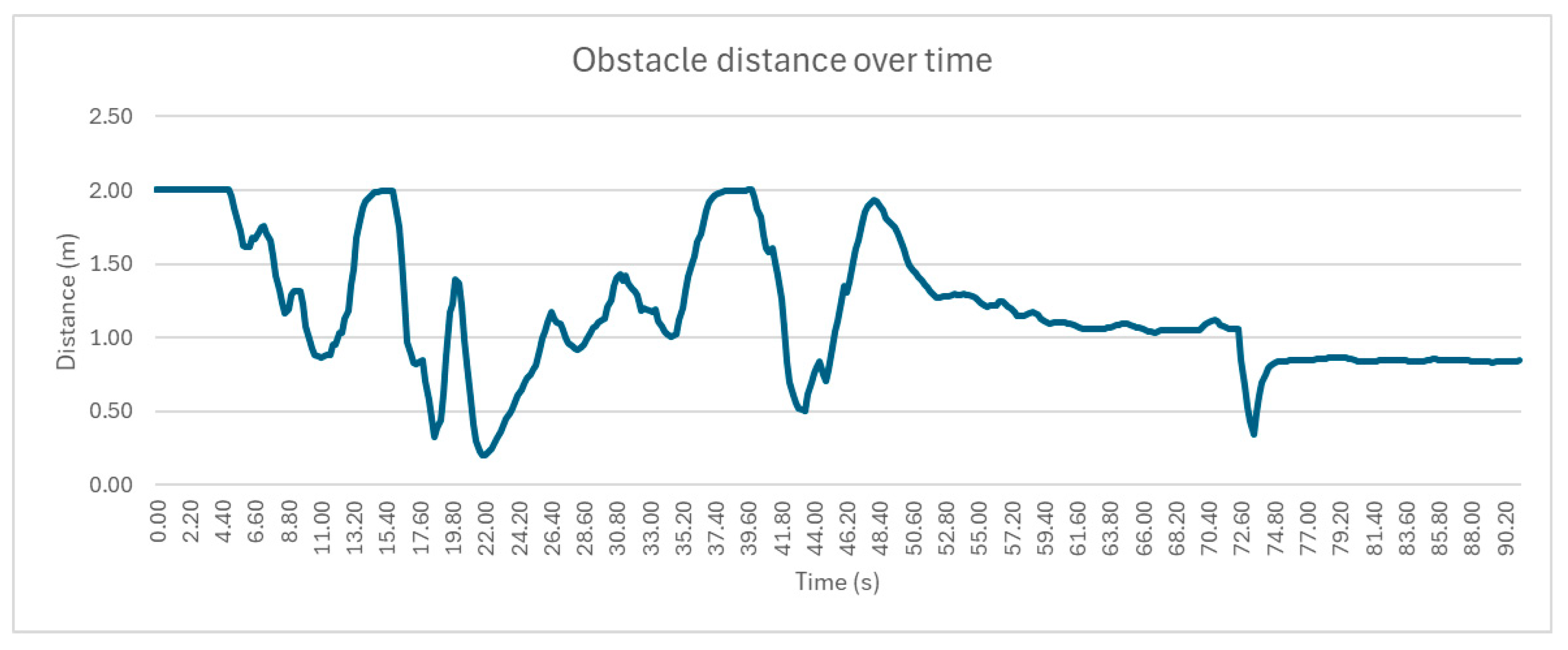
In the second test, the RPSC moves towards a specific point with a person acting as a moving obstacle. The avoidance distance was set to 1 m. The RPSC adjusts its position in response to the presence of the person. The RPSC is instructed to move to a certain point, and the person positions themselves in its path, with the avoidance distance set to 1 m. The RPSC stops and slightly retreats. Then, the person moves randomly in front of the RPSC, approaching and moving away. The RPSC responds appropriately: when the person moves away, the RPSC advances, but if the person approaches again, the RPSC retreats to maintain the distance. This test corresponds to
Figure 17, which shows a noisier graph due to the real scenario and the sensor detecting a moving foot, not a flat wall.
The measurement results showed a significant difference between the methods used. The average deviation in pure measurement was 0.105 m, while mean filtering and Kalman filtering reduced this deviation to 0.085 m and 0.073 m, respectively, improving measurement accuracy. The standard deviation for pure measurement was 0.115 m, reduced to 0.096 m with mean filtering and to 0.082 m with Kalman filtering, suggesting a reduction in variability and noise in the measurements.
The maximum deviation in pure measurement was 0.402 m, while mean filtering reduced it to 0.305 m and Kalman filtering to 0.238 m. The minimum deviation also decreased, from 0.002 m in pure measurement to 0.001 m with mean filtering and 0.001 m with Kalman filtering. These results reinforce the conclusion that Kalman filtering provides more accurate and stable measurements than other methods.
In conclusion, the comparative analysis between mean filtering and Kalman filtering in a real environment with a moving obstacle shows that, although both methods improve distance measurements compared to raw data, Kalman filtering stands out for its higher accuracy and stability. This makes it the preferred option for applications that require reliable and high-precision measurements, especially in dynamic environments where obstacles can vary.
4. Discussion
This review of the state of the art reveals a clear trend in current work towards demonstrating multi-agent navigation, control, and formation algorithms using mobile platforms that integrate a traffic cone on their upper part. However, in most cases, the development focuses on the platform’s autonomous movement without addressing the structural, regulatory, and safety requirements that would allow such a system to be considered a fully functional robotic traffic cone.
Cone formation systems have employed commercial autonomous vacuum cleaners, such as the iRobot Roomba 600 series, as mobile bases [
18,
26]. This robot was originally designed for indoor domestic environments and is not prepared to operate on uneven terrain such as asphalt, gravel, or construction zones. Furthermore, its structure has exposed elements, such as power and communication wiring, representing a risk of improper manipulation. The system lacks safety mechanisms that would allow for its deactivation in the event of failure or external intervention, and it does not comply with European road regulations, such as UNECE R65 [
23] or UNE-EN 13422:2019 [
22], which renders its deployment in real-world environments impossible.
An autonomous positioning system using computer vision, based on lane line detection through image segmentation and Hough transforms, was proposed in [
21]. Although this approach enables the validation of navigation algorithms, it does not account for real-world construction scenarios where road markings may be absent or altered, as is often the case. Additionally, the platform incorporates a small cone, similar to those used in sports training, which does not meet the visibility, stability, and structural resistance requirements for road signage. Neither an absolute positioning system nor active safety measures are included.
Other studies have focused on predictive control and formation tracking using robust mathematical models [
20,
26]. However, these approaches are mainly validated in simulated or laboratory environments without considering the integration of high-precision GNSS sensors, incorporating redundant safety mechanisms, or complying with active signaling regulations. Likewise, the structure of the developed prototypes remains based on generic mobile platforms, on which a cone is mounted, without designing an integral element that could be approved as a signalling device.
An approach based on reinforcement learning has been proposed, in which a simulated agent is trained to achieve objectives within a virtual environment [
17]. While this work offers interesting autonomous control methodologies, it lacks validation under real-world conditions and does not address visibility, structural safety, or signalling regulations.
Initial proposals introducing bright traffic cones with GNSS-based detection and alert capabilities have remained focused on passive and static functionalities, without addressing mobility, environmental interaction, or integration with autonomous systems [
16].
Collectively, these works have contributed to validating navigation, tracking, or autonomous learning algorithms using mobile structures that carry cones; however, they have not addressed the fundamental problem of designing and implementing a robotic traffic cone that can operate autonomously, accurately, and safely in real-world road environments.
The approach presented in this work begins with a fundamentally different conception: to develop a functional and autonomous robotic traffic cone. From its structural and electronic design to its navigation and control logic, the system has been conceived to comply with all current European regulations regarding active signalling (UNECE R65 [
23]), structural and mechanical resistance (UNE-EN 13422:2019 [
22]), luminous visibility (UNE-EN 12352:2006 [
25]), and electrical safety (UNE-EN 12899-3:2008 [
24]).
The RPSC incorporates a structured operational lifecycle composed of the INITIALISING, WAITING RTK, FOLLOWING, ALERTING, and SHUTDOWN states, managed through a modular architecture based on ROS2. This cycle allows the system to autonomously control its transition between states based on the status of GNSS positioning, the detection of external events, the reception of remote commands, or the occurrence of internal failures.
In terms of navigation, the system integrates a sensor fusion scheme based on GNSS with RTK, encoder odometry, and inertial estimation, enabling the maintenance of high trajectory precision. In tests performed under optimal configuration, the system achieved an average positioning error of 0.12 m and an average route deviation of less than 0.20 m. These metrics confirm the system’s feasibility for precise operations in real road areas, where exact cone placement is required to define safety perimeters and work zones.
To contextualize the performance of the RPSC, it is essential to compare it with the time required for manual deployment of traffic cones in real-world work zone scenarios. Field studies and government reports indicate manual cone placement is labour-intensive and time-consuming. According to Highways England, the manual assembly of a 1 km lane closure by two operators typically takes about 15 min, which equates to an average cone placement rate of approximately one cone every 7 to 8 s [
27]. Moreover, this task generally involves transporting multiple cones simultaneously, which increases physical fatigue and reduces the operator’s average walking speed from approximately 1.4 m/s unloaded to as low as 0.78–0.82 m/s when carrying loads exceeding 10 kg [
28,
29]. This, in turn, increases the total time required to delimit large-scale work areas.
In contrast, assuming a standard cone spacing of approximately 10 m and a maximum speed of 12 km/h (≈3.33 m/s) for the RPSC—achieved using 248 RPM motors and 135 mm diameter wheels—the estimated time to position each cone would be roughly 3 s, which is significantly lower than that of manual operations. This direct comparison highlights the operational superiority of the automated system, both in reducing the time required for road zone segmentation and in minimizing worker exposure to vehicular traffic.
This design allows for safe deployment in work zones and lays the groundwork for future research in multi-agent coordination, integration with intelligent construction management systems, and predictive risk analysis in road maintenance areas.
The proposed hardware and software architecture has been designed to support scalable multi-agent operations to address the control and coordination of multiple RPSC units. ROS2 middleware enables each RPSC to operate as an independent node within a distributed network, using unique namespaces and individual identifiers to ensure isolated management of commands and telemetry for each unit.
Remote control and supervision are achieved via a central ground control station (GCS), which communicates with all RPSC units through a ROS2-based interface. The GCS can issue individualized and group commands using ROS2 topics and services that manage structured messages for navigation, alarm activation, or operational state changes. Each RPSC exposes these topics within its namespace, allowing it to receive and execute commands synchronously or independently, depending on the operational requirements.
Communication between the GCS and the RPSCs is handled securely and efficiently over Wi-Fi networks, with the ROS2 DDS backend ensuring automatic discovery, low latency, and the integrity of critical messages. This setup enables, for example, the coordinated activation of formations, delivery of planned trajectories, or the immediate transmission of emergency stop commands to one or several units.
5. Conclusions
In this paper, we present the development of an RPSC designed to enhance safety and efficiency in road work zones. This work aligns with the InfraROB project’s objectives, which are to contribute to advancing robotic solutions in infrastructure maintenance. It has been demonstrated that the combination of RTK sensors, encoders, IMU, and data fusion systems, such as EKF, enables robust navigation, ensuring the precise delimitation of work areas and reducing risks for operators.
The developed software facilitates autonomous control of RPSCs, providing essential capabilities such as autonomous navigation, obstacle detection and avoidance, real-time data processing, and remote visual alarm management. This system proves to be an effective and practical solution for dynamic and hazardous environments.
For future lines, the development of software capable of simultaneously controlling multiple RPSCs is envisaged, providing the possibility of implementing coordinated formations and real-time tracking of heavy machinery, such as pavers, or other vehicles within construction sites. This will require implementing distributed multi-agent coordination algorithms and collaborative control techniques.


 ,
, 


