1. Introduction
As the development of rock tunnels continues, the scale of construction of underground works continues to expand, and the proportion of deeply buried tunnels grows rapidly. However, the high-ground-stress problem faced by these tunnels has become a major challenge in the field of tunnel construction. Long-term deformation of the rock under high geopathic stresses results in increasing pressure on the tunnel lining structure, posing a serious challenge to the safety and stability of the tunnels during operation [
1]. It is worth pointing out that the judgment of high geopathic stress is a relative concept, determined not solely by the magnitude of geopathic stress, but also by the ratio of the maximum stress exerted by the surrounding rock to the strength of that surrounding rock [
2]. Regarding the grading of ground stress, although it has been studied for many years, a unified standard has not yet been formed. The Design Code for Road Tunnels [
3] states that when the ratio of the maximum stress exerted by the surrounding rock to its strength falls within the range of 4 to 7, it is recognized as a high geopathic stress, while when the ratio is less than 4, it may be regarded as a very high geopathic stress zone. The implementation of this specification provides a more scientific and accurate basis for the discrimination of high ground stress in tunnel engineering.
With the increasing prevalence of high-ground-stress tunnels, many researchers have delved deeper into their study, conducting comprehensive and systematic analyses of the damage mechanisms affecting the surrounding rock under extreme geological conditions. Due to the complexity and variability of the rock environment, numerical analysis has emerged as an effective research tool widely utilized in the investigation of tunnel-related disasters. Wei [
4] examined the deformation mechanisms of high-ground-stress soft rock in the context of deeply buried tunnels. He established a three-dimensional numerical model using finite element software to simulate various construction methods and to compare their advantages and disadvantages. Yuan [
5] investigated the significant deformations of soft rock under high ground stress. By simulating construction methods and anchorage parameters with finite difference software, he successfully applied optimized methods and parameters to real-world projects, yielding positive results. Feng et al. [
6] analyzed the specific effects of the lateral pressure coefficient and burial depth on the deformation of surrounding rock. Their findings revealed that the deformation was influenced by both the lateral pressure factor and burial depth, particularly highlighting that an increase in the lateral pressure coefficient markedly affects the bottom uplift phenomenon. N. K. Men et al. [
7] combined numerical simulation techniques with field observation data to investigate the deformation mechanisms of deep soft rock tunnels under dynamic pressures, proposing targeted control measures based on their findings. Guo et al. [
8] introduced an innovative numerical simulation approach that incorporates the creep characteristics of the rock body, enhancing the accuracy of deformation predictions for high-stress soft rock tunnels and thoroughly analyzing the potential impact of creep on prediction outcomes. Deng et al. [
9,
10,
11] further focused their numerical simulations on the pronounced deformation characteristics of high-stress soft rock tunnels under unloading conditions and examined the causative mechanisms behind the soft rock bottom bulge. Concurrently, Xue et al. [
12,
13,
14,
15,
16] applied discrete element numerical simulation to analyze the dynamic damage processes and characteristics triggered by unloading during deep soft rock tunnel excavations. Dong et al. [
17] utilized the finite difference method to simulate the stress state, deformation, and damage modes of surrounding rock after tunnel excavation, both with and without consideration of tectonic stress. Their work explored the influence of the tectonic stress field on the stability of tunnel surrounding rock and the resulting deformation and damage patterns. Zhou et al. [
18] investigated the stress–time distribution curves for secondary lining, illustrating three distinct stages throughout the construction process and providing valuable insights and guidance for tunnel construction practices.
In order to deeply explore the safety performance of surrounding rock lining under extremely high-ground-stress environments and to scientifically and accurately assess the overall safety of tunnels, researchers have widely adopted the reliability theory, which can reflect the parameter uncertainty, and developed a series of advanced reliability analyses methods based on it. Do et al. [
19] conducted an investigation into the assessment of time-varying reliability concerning the rheological characteristics of surrounding rock and the lining construction of deeply buried circular tunnels. They employed the established closed-form analytical solution as a tool for performing time-varying reliability analysis utilizing Monte Carlo simulation. Wang et al. [
20], on the other hand, proposed an innovative method for time-varying reliability analysis of damage in underground tunnels, which is based on the probability-density evolution method and introduces the creep damage theory to accurately simulate the time-varying properties of rock materials. Chen Vanadium et al. [
21] constructed corresponding time-varying reliability calculation models for various damage modes of gypsum perimeter rock tunnels, including expansion damage of lining structure, corrosion damage, and comprehensive damage modes, and further adopted the reliability model under the comprehensive damage modes of gypsum perimeter rock to comprehensively analyze the safety of the tunnels.
Although some progress has been made in the research of tunnel lining under high ground stress, there are still many urgent problems to be solved. This paper combines numerical simulation and time-varying reliability and establishes a time-varying reliability model of tunnel lining considering the evolution of the plastic zone based on the cracking damage mode of the lining by using numerical simulation and the Monte Carlo method, so as to calculate the time-varying reliability and damage probability of the tunnel lining under very high geopathic stresses, which ensures the stability and reliability of the tunnel during operation and guides the lining structural maintenance program, which is of important scientific research value and engineering significance.
2. Analysis of Damage Modes of Tunnel Linings in Very-High-Stress Tunnels
The tunnel lining is a vital structure in tunnel engineering, providing the necessary support and protection for the interior of the tunnel. However, with the passage of time and changes in the external environment, tunnel linings may develop different types of distress, which can usually be categorized into three main groups: lining movement, lining deformation, and lining cracking.
2.1. Lining Movement
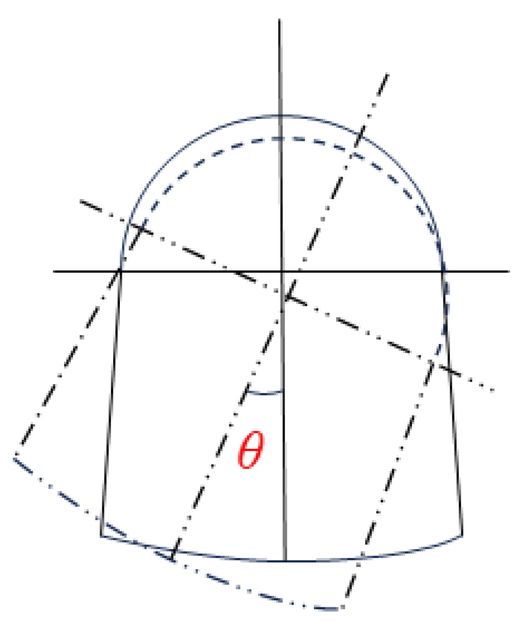
An example of lining movement disease is given in
Figure 1. Axial movement disease is the displacement of local segments or the whole of the lining in the direction of the tunnel axis after being stressed. This phenomenon is usually caused by settlement of the surrounding rock, changes in surface loads, or fluctuations in the water table. In the case of axial movement, the lining may translate up and down, leading to an uneven distribution of support forces and thus increasing the stresses on the structure.
Horizontal movement disease is manifested as displacement of a localized cross-section of the lining along the vertical axis of the section. This displacement is usually caused by local changes in geological conditions, earthquakes, or changes in groundwater pressure. When the lining moves horizontally, it may have an impact on the stability of the tunnel, increasing the risk of possible cracking. In environments with complex forces, these two movements are often a combination of multiple displacements, creating more complex deformation behavior. For example, simultaneous axial and horizontal movements may lead to interactions that further exacerbate the incidence of cracking.
2.2. Lining Deformation
Axial deformation is usually closely related to the physical properties of the lining material and the distribution of external loads. During tunnel construction or operation, if the surrounding rock is subjected to excessive loads, the lining may compress or extend in the axial direction, leading to overall structural instability. Such deformations, although they may not be apparent initially, can lead to serious cracking or other damage over time, as shown in
Figure 2.
Horizontal deformation is the deformation of a cross-section caused by localized unbalanced forces, a phenomenon that is particularly common in areas where the geological structure surrounding the tunnel is complex. Common manifestations include depressions or bulges in the tunnel, which may be due to instability of the surrounding rock, infiltration of groundwater, or defects in the construction process. Horizontal deformation not only affects the normal functioning of the structure, but may also lead to secondary damage and, in severe cases, may even affect the structural safety of the tunnel.
2.3. Lining Cracking
Tunnel lining cracking is one of the most severe manifestations of structural defects. The ultimate result of lining movement and deformation is cracking, which signifies the deterioration of the lining structure. Cracking of the lining primarily includes tensile cracking, crushing, and shear cracking.
2.3.1. Bending Cracking
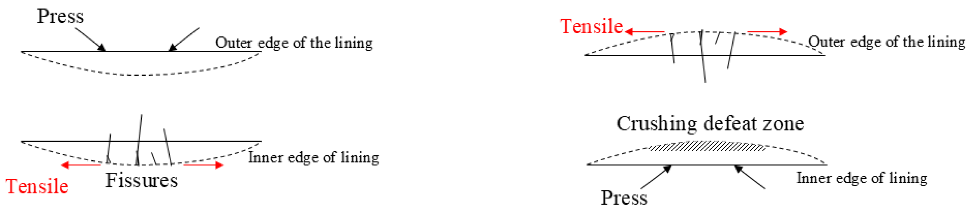
Bending cracking usually occurs when the outer edge of a lining structure is compressed under external forces, while the inner edge is subjected to tensile forces. When the tensile stress increases to a certain extent, tensile cracks may appear on the inner edge. Bending cracking not only affects the overall stability of the tunnel, but also reduces the bearing capacity of the lining. If the cracks expand, they may lead to water infiltration as well as soil instability, increasing the difficulty of maintenance.
2.3.2. Crushing and Compression Shear Cracking
Crushing and compression shear cracking, on the other hand, occur under excessive pressure or uneven forces. Crushing cracking is usually characterized by separation of lining materials and volume reduction, with crushed areas generally distributed in a network, accompanied by concrete spalling. Compression shear cracking, on the other hand, is caused by transverse forces, resulting in lining interlayer shear damage, and is a crack caused by high-stress extrusion of the lining structure, as shown in
Figure 3. The occurrence of both is often closely related to external geological conditions, construction quality, and material properties.
3. Time-Varying Reliability Modeling of Very-High-Ground-Stress Lining Structures
Time-varying reliability is the characteristic change in the reliability of a structure over time during its service life due to material deterioration, changes in external loads, etc. It is important to consider time-varying reliability for lining structures under very high ground stresses, since changes in ground stresses may lead to damage or failure of the lining structure.
3.1. Equation for Solving the Reliability Index Based on the Volume Ratio of the Plastic Zone
Reliability indices based on plastic-zone volume ratios are commonly used to assess the resistance of a structure under different loads in relation to its failure mode. At very high ground stresses, the resistances and loads are usually treated as random variables that can be modeled using probabilistic statistical methods:
In the formula, R(t) is the resistance effect of the structure, and S(t) is the load effect of the structure.
The lining structure resistance effect is the ratio of the volume of the plastic zone to the volume of the lining structure in the critical state of lining failure. The effect of the plastic zone on the resistance can be introduced when the plastic-zone volume ratio is considered. Assuming that the resistance
R can be expressed by a certain effective load carrying capacity generated by the volume of the plastic zone; then,
Among them, is the initial resistance without plastic damage, and is the correction coefficient based on the volume ratio of the plastic zone, which can be determined by calculation and testing with reference to the importance of the structure.
For a given lining structure, under the determined boundary conditions and its own parameters, the stress state at its internal points can be obtained according to the elastic–plastic theory as follows:
In the formula, is the stress state of any point inside the lining, s is the shape parameter of the lining structure, p is the mechanical parameter of the lining structure, is the stress boundary condition of the lining structure, and is the displacement boundary condition of the lining structure.
Based on the given conditions, the stress state at various points inside the lining can be obtained by analysis. The stress state can be expressed in terms of a first- or second-order tensor, consisting mainly of shear and plane stresses. After obtaining the stress state at each point, the criterion of strength from elastoplastic theory is employed to determine whether each point has entered the plastic state. The combination of all points that have entered the plastic state constitutes the overall volume of the section of the lining structure that has entered the plastic state. This process is the integration of three (
x,
y,
z) directions:
In the formula,
is the volume of the plastic zone in lining structure,
m is the determinant of the plastic state, and
dv is the volume differential.
m has different forms of expression according to different strength criteria, such as the Drucker–Prager criterion, commonly used in engineering as a judgment of whether a rock body enters into plastic yielding under external force [
22], as shown in Equation (5):
In the formula, is the first invariant of stress; is the second invariant of the stress deviator ; K is a constant.
By calculating the ratio
S between the volume of the plastic zone and the total volume
V of the lining structure, an indicator of the load effect can be derived:
Based on the plastic-zone volume ratio of the reliability index solution formula, the joint formulas (1), (2) and (6) can be obtained in the reliability analysis based on the plastic-zone volume ratio of the structural function of the structure function as Equation (7):
3.2. Time-Varying Reliability Modeling of Lining Crack Damage Mode
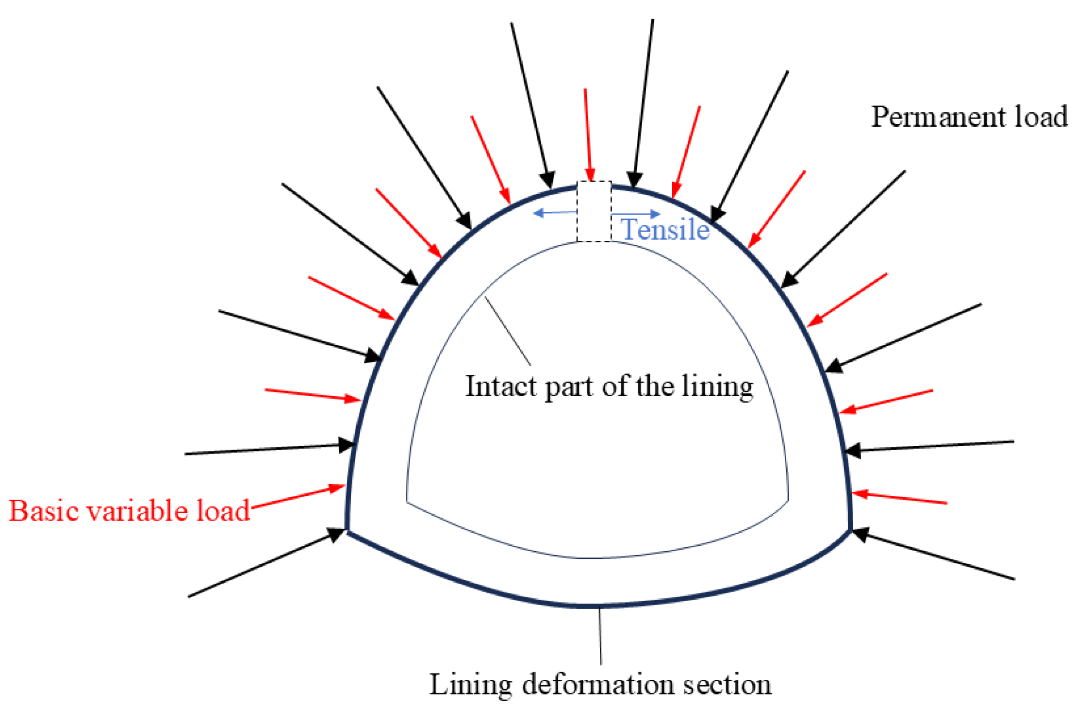
Under the premise of extremely high stress, the displacement boundary of the lining varies under the lining movement failure mode, as shown in
Figure 4. In the lining deformation failure mode, the shape and strength parameters of the lining structure change over time, while the stress boundary remains unchanged. Therefore, a comprehensive analysis of the lining crack damage failure mode reveals the stress state at various internal points of the lining as follows:
In the formula, is the shape parameter of the lining under the comprehensive failure mode, is the strength parameter of the lining under the comprehensive failure mode, is the stress boundary condition of the lining under the comprehensive failure mode, and is the displacement boundary condition of the lining under the comprehensive failure mode.
According to Kachanov–Rabotnov’s classical damage mechanics theory [
23], changes in strength parameters of the lining structure can be translated into a reduction in the effective bearing area, and changes in the effective bearing area can be determined by the amount of change in displacement deformation. Considering the rheology of surrounding rock [
24], the displacement of tunnel lining can be expressed by Equation (9):
In the formula,
is the rheological parameter of surrounding rock, and
t is time.
In the formula,
is the elastic modulus of the initial lining and
is the elastic modulus of the surrounding rock. For
, the inverse calculation of parameters can be carried out by fitting the field settlement data [
25].
In this case, the internal stress state is still a time-dependent second-order tensor.
Similarly, the combination of all the points where the stress enters the plastic state is the volume of the plastic zone within the lining structure at this point in time, where the plastic state determination is the same as in the previous section.
Due to the deformation of the lining structure, the total volume of the lining structure changes at this point. Establishing the structure function can be considered as changing the lining into a new lining structure. Focusing on the new lining structure, the total volume of the deformed lining structure is obtained from the shape parameters of the deformed tunnel lining structure as a function of time:
Then, the load effect can be calculated.
Due to the change in total volume due to deformation, the ratio of the volume of the plastic zone to the volume of the lining structure in the critical state of failure will change compared to the original lining structure and can be reduced according to the overall volume of the lining structure:
Similarly, the structural function of the lining structure in the combined damage mode can be established from Equations (1), (13) and (14) as Equation (15):
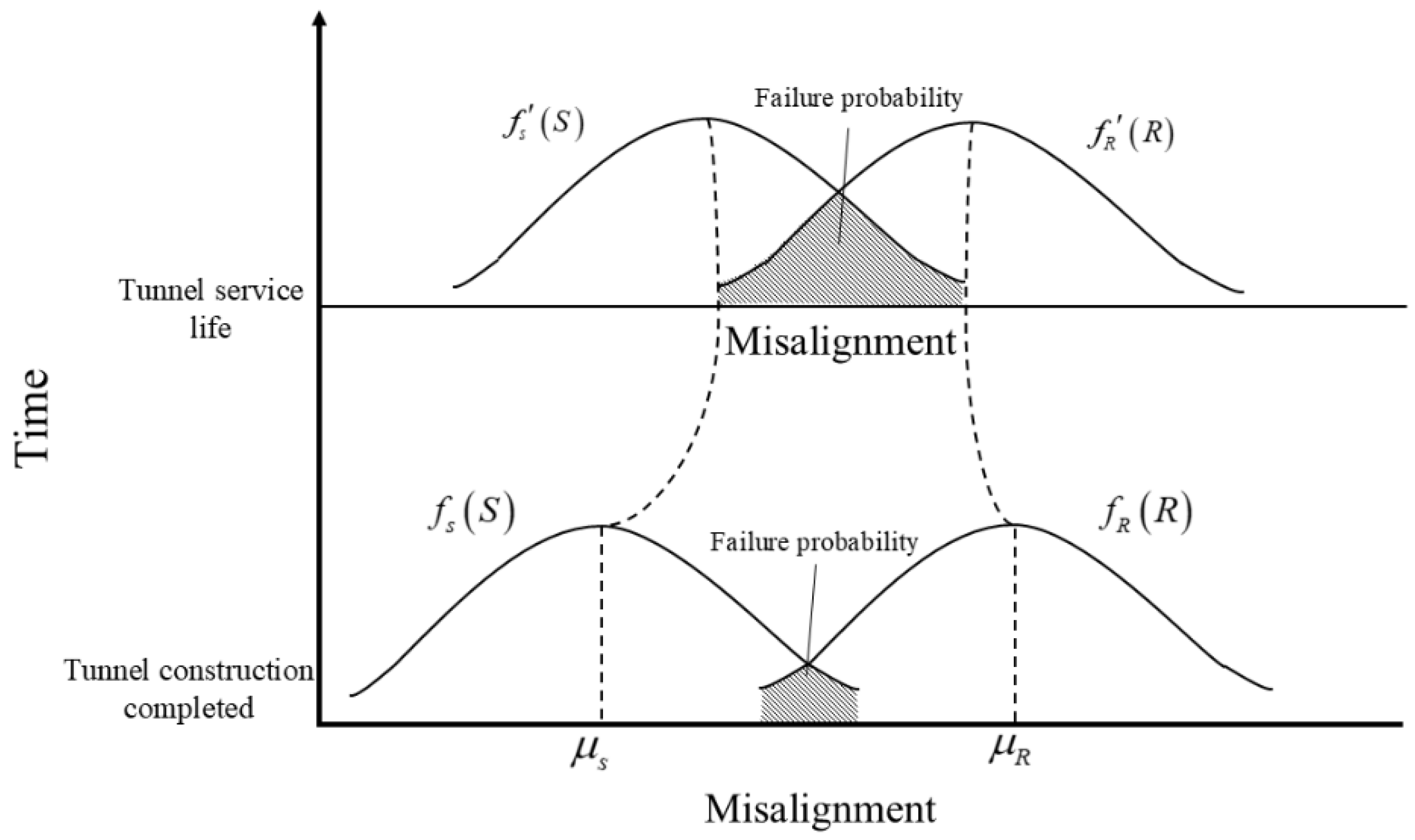
In the time-varying reliability analysis of lining crack damage, with the increase in time, the load effect of tunnel lining structure increases, the resistance effect decreases, the failure probability of the lining structure increases, and the reliability decreases. The time-varying failure probability is shown in
Figure 5.
is the load effect distribution function when the tunnel construction is completed,
is the load effect distribution function after a period of tunnel operation,
is the lining structure resistance distribution function when the tunnel construction is completed,
is the load effect distribution function after a period of tunnel operation,
is the load average value when the tunnel is put into use, and
is the lining structure resistance average value when the tunnel is put into use.
3.3. Monte Carlo Method
Monte Carlo Method is a numerical computation method based on random sampling and is widely used in various fields. In time-varying reliability analyses of tunnel linings, the Monte Carlo Method is used to assess and predict the performance and reliability of lining structures under the influence of uncertainties. In tunnel engineering, the reliability of the lining is affected by a variety of uncertainty factors, the variation of which affects the safety and durability of the tunnel lining, and hence the need for a variable reliability analysis.
The basic principle of the Monte Carlo method is to generate a large number of pseudo-random numbers that are representative of the actual distribution of a set of underlying random variables. The probability distributions of the random variables are first defined and then transformed using uniformly distributed pseudo-random numbers that map onto the actual distributions of these random variables. By substituting these random variables into the mathematical expression of the structural performance through the performance function, the response of the system is calculated. Finally, the number of times the system fails in a large number of simulations is counted to obtain the failure probability, i.e., the ratio of the number of failures to the total number of simulations. The Monte Carlo method has the advantage of not being restricted by limit state equations and the type of distribution of random variables and thus provides a powerful tool for reliability analyses of various complexities in engineering. It is not only very intuitive and accurate but also has good generality and is particularly effective for higher-order nonlinear problems. These properties make it a standard means of comparison with other reliability analysis methods. The structural and loading models of tunnel linings are developed according to the specific conditions of the tunnel project, usually using numerical calculation methods such as finite element analysis.
4. Application Examples
4.1. Numerical Simulation Analysis of Tunnel Excavation
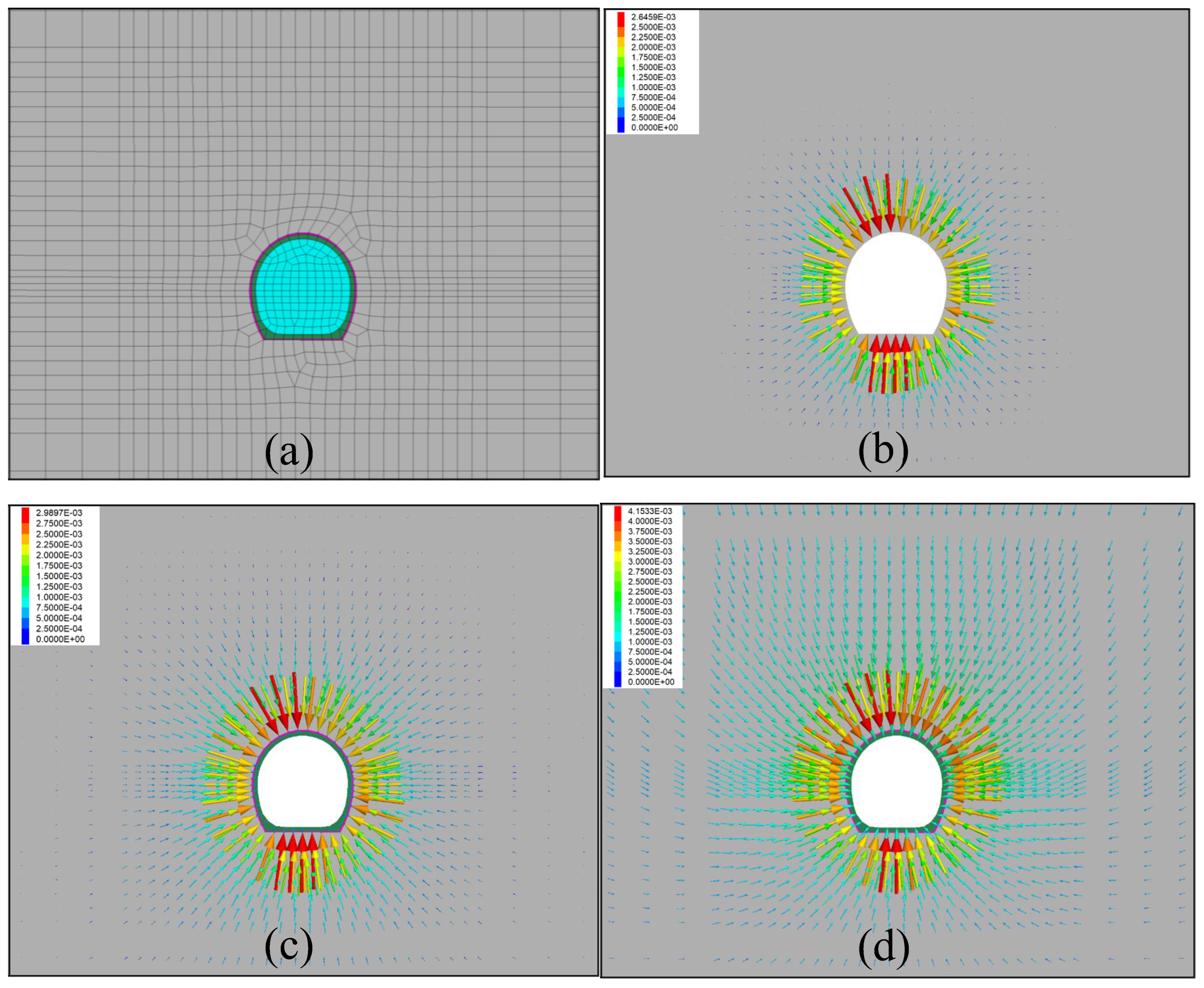
Taking the tunnel of the Tibet Railway as an example, the stress gradual release is adopted to consider the time–space effect during the tunnel construction process. According to the construction design of a certain tunnel SD3 section, the left and right sides of the model are taken to be 5 times larger than the span of the excavated section, and the bottom of the model is 3 times larger than the height of the excavated section. The specific dimensions of the model are 60 m horizontally, 442 m from the top of the arch to the ground surface, 30 m vertically, and 0.5 m vertically; fine cells are used in the vicinity of the tunnel structure, and the grid of the model in the vicinity of the tunnel structure is shown in
Figure 6a.
The tunnel was excavated by the full-section method and the support structure was designed by the Neo-Method. In the calculation, the stress release rate before applying initial support after tunnel excavation is considered to be 0.5; the stress release rate before secondary lining after applying initial support is 0.8; and the stress release rate after secondary lining is completed is 1.0.
Figure 6b shows the distribution of displacement vectors of the surrounding rock at 50% stress release before initial support after tunnel excavation. The maximum displacement occurs at the arch top with a maximum displacement of 3.96 mm, accounting for 81.5% of the total final displacement.
Figure 6c shows the displacement vector distribution of the surrounding rock at 80% stress release after the completion of initial support, and the maximum displacement is 4.08 mm, accounting for 83.9% of the total displacement.
Figure 6d shows the final displacement vector distribution of the surrounding rock at 100% stress release after the completion of the second lining, and the maximum displacement is 4.86 mm. The displacement field around the tunnel shows that the arch is sinking, and the inverted arch is bulging. It can be seen that the arch and the inverted arch are the main control parts of the construction. If necessary, these parts should be locally strengthened.
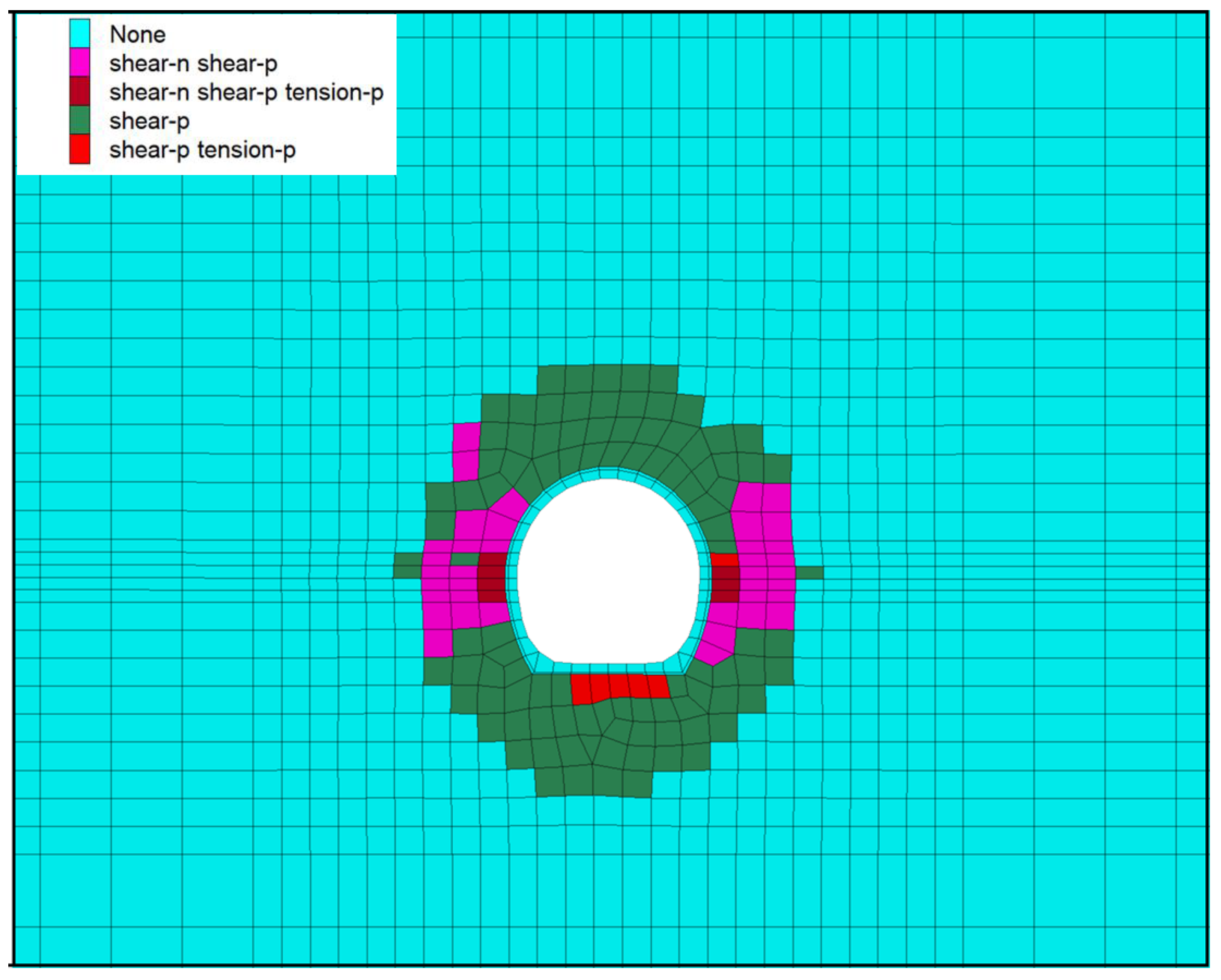
Figure 7 illustrates the distribution of the plastic zone in the surrounding rock of the tunnel. The plastic zone mainly surrounds the arch top, the side walls on both sides, and the bottom area of the tunnel, forming an approximate horseshoe-shaped area. This indicates that in these areas, the surrounding rock is subjected to large stresses, resulting in plastic deformation of the rock mass. The plastic zone is particularly pronounced at the junction of the vault and the sidewalls, indicating that these are areas of concentrated stress. A large plastic zone was formed in the surrounding rock of the tunnel, reaching 3 m in the longitudinal direction.
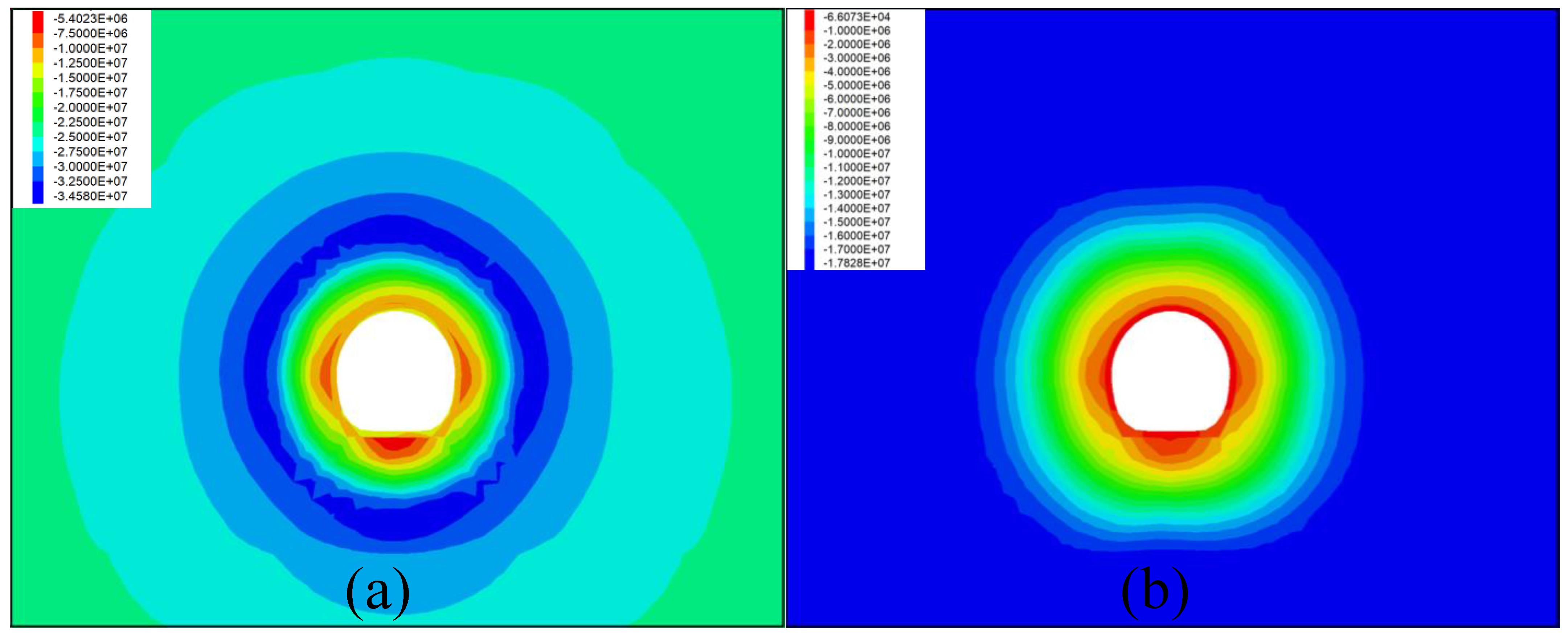
The stress field of the tunnel’s surrounding rock also changes significantly during tunnel construction.
Figure 8 shows the distribution of the final first and third principal stress fields in the surrounding rock, respectively. The surrounding rock stresses show a symmetrical distribution of the magnitude of the principal stresses, which varies greatly around the cavern and varies less away from the cavern. From the distribution of the third principal stress, the surrounding rock is undergoing compressive stress around the cave chamber, and tensile stress occurs locally at the bottom of the arch. From the distribution diagram of the first principal stress field, the stress distribution is more uniform, and the stress concentration area increases with the increase in depth and then decreases.
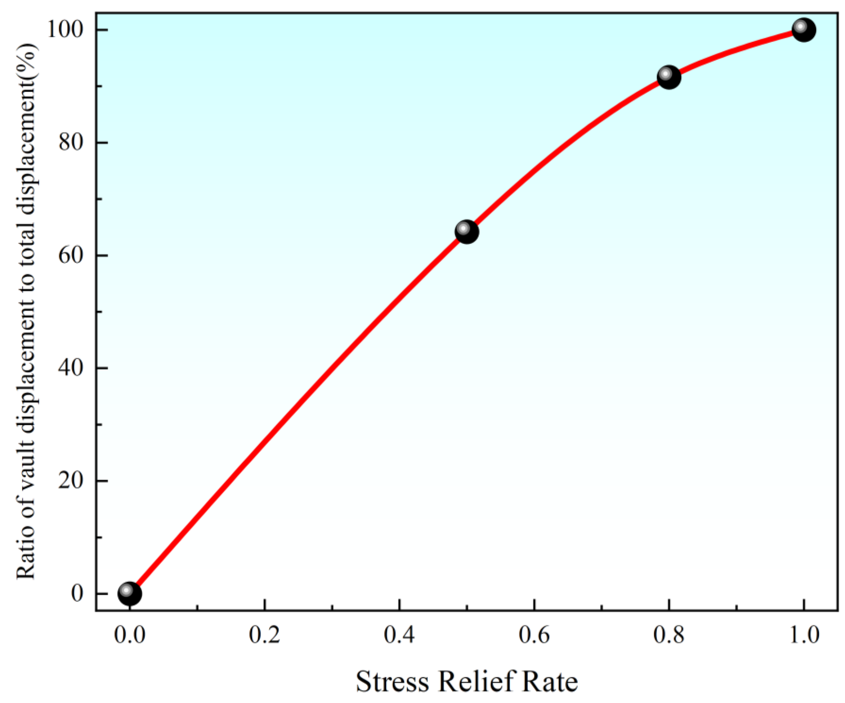
Figure 9 shows the relationship between the displacement of the vault and the stress release rate. From
Figure 9, it can be seen that 50% of the stress is released after excavation, and the displacement reaches 64.2% of the total displacement; at this time, the entire load is borne by the surrounding rock. After the initial support, the stress is released by 30%; the displacement increases by 27.4%, and the load is borne by the surrounding rock and the initial support. After the second lining is completed, the stress is released by 20% and the displacement increases by only 8.4%, at which time the load is borne by the surrounding rock, the initial support, and the secondary lining. It can also be seen from
Figure 9 that the displacement increases with the increase in the stress release rate, which reflects the spatial and temporal effects in tunnel construction. At the same time, the displacement rate slows down with the increase in the stress release rate. Therefore, the timely application of initial support in tunnel construction is very important to suppress the deformation of surrounding rock (especially weak surrounding rock).
4.2. Time-Varying Reliability Analysis
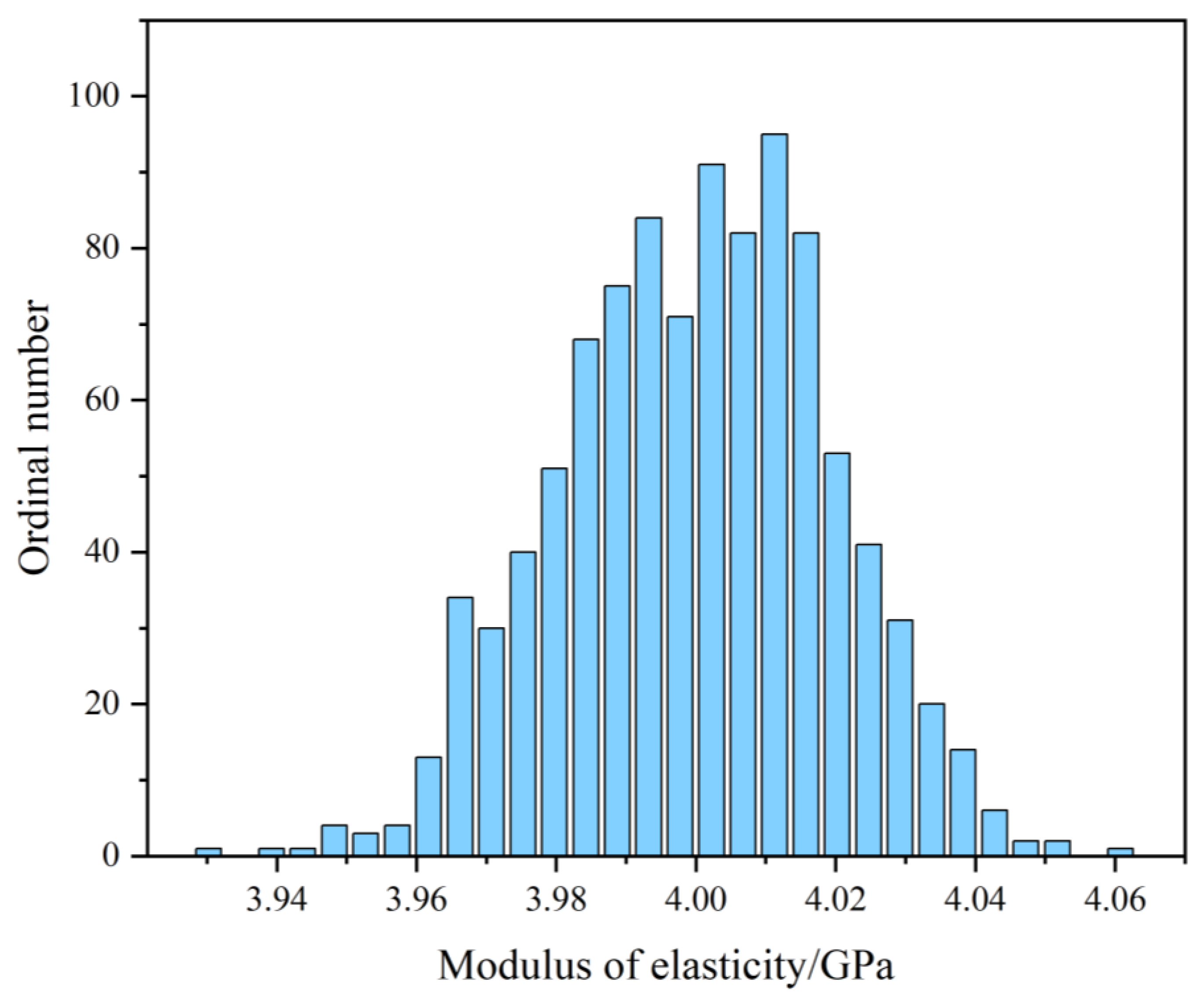
The time-varying reliability and failure probability of the tunnel lining were analyzed based on the Monte Carlo method with different moduli of elasticity. The tunnel was analyzed using the established time-varying reliability model under the cracking damage mode of the lining, and the reference slope was marked by generalized plastic strain or equivalent plastic strain penetrating from the foot of the slope to the top of the slope as a sign of damage. From the structural durability requirements, load carrying capacity requirements, and normal use requirements, the allowable crack width is 0.1 mm. Therefore, in the plane strain problem, the critical percentage (a) of the plastic zone when the lining fails is
In the formula, is the thickness of the lining structure.
The sample size is set to 1000 and the Latin Hypercube sampling technique of the Monte Carlo method is used to obtain the sample values of the main random variables required for structural reliability calculations. By referring to the relevant codes and field measurements, the distribution form and parameters can be obtained as shown in
Table 1.
In this paper, the reliability analysis of the structure can be divided into three segments:
- (1)
Obtain the variation in rock index Z (structural functional function) with time for different material properties and save it in an Excel sheet. This can be achieved by setting different material properties, performing several simulations, and exporting the results to an Excel file.
- (2)
Obtain the changes in indicator Z (structural functional function) over time in all Excel files in the batch; count the number of its occurrences greater than 0 and less than 0 at different time steps; extract the value of indicator Z; and count the number of values greater than 0 and less than 0.
- (3)
Extract the probability that the structural function is less than 0, which is the probability of failure of the lining structure. Then, the inverse cumulative distribution function is used to calculate the reliability of highly stressed soft rock tunnels at different time steps.
Figure 10 and
Figure 11 show the trend of the time-varying reliability and probability of failure of the tunnel lining with time, which were investigated using the Monte Carlo method as well as on the basis of the elastic modulus of rock. The probability of failure reflects the effect of the gradual accumulation of damage, aging, and other effects on the tunnel structure during operation. Time-varying reliability is a measure of a structure’s ability to maintain normal operation at different points in time.
The trends of failure probability and time-varying reliability over time are demonstrated in
Figure 10 and
Figure 11, which are consistent with the rock creep characteristics. From the point of view of damage expansion and fracture expansion, the failure probability gradually increases and the time-varying reliability gradually decreases, reflecting the accumulation of damage and performance degradation of the tunnel structure during long-term operation. In the initial stage (0–10 years), the crack extension and damage accumulation are faster, and the stress concentration inside the structure accelerates the formation and extension of cracks, leading to a faster rise in the probability of failure and a rapid decline in reliability. With the passage of time, the damage expansion gradually slows down, the crack expansion slows down, and the rate of increase in the probability of failure slows down. After about 40 years, crack propagation and damage accumulation tend to be stable, which shows that the growth of failure probability becomes gentle and the reliability tends to be stable, indicating that the structure has entered a relatively stable operating state and the creep effect is reduced. In general, these curves not only reflect the characteristics of attenuation creep and steady-state creep, but also reveal the time-varying characteristics of failure probability and reliability of the tunnel structure during operation. Although the tunnel structure has certain reliability, it is still necessary to pay attention to maintenance and reinforcement to mitigate the failure risk caused by damage accumulation.
5. Discussion
In this study, a time-varying reliability model of tunnel lining structures under very-high-ground-stress conditions was established based on the Monte Carlo method, focusing on analyzing the effects of the stochasticity of mechanical parameters, such as modulus of elasticity, Poisson’s ratio, and density, on the reliability. The results show that the reliability of the lining structure in the very-high-ground-stress environment exhibits an obvious nonlinear decay characteristic with time; however, there are still some limitations in this study, which are worth further exploration.
First, in terms of material parameter considerations, this paper only incorporates basic mechanical parameters such as modulus of elasticity, Poisson’s ratio, and density, without considering the effects of plasticity and creep parameters. In fact, the plastic deformation and creep effects of lining materials are not negligible under very-high-ground-stress conditions. It is foreseeable that the consideration of the creep effect can make the reliability calculation results lower. It is recommended that a secondary creep constitutive model be introduced in subsequent studies to more accurately describe the time-varying mechanical behavior of the material.
Secondly, the effect of lining interlayers is not considered in this paper. In actual engineering, there are often weak interlayers or devoid zones between the lining and the surrounding rock, and these defects can significantly change the stress distribution pattern. Therefore, it is recommended to introduce the thickness of the interlayer and the mechanical properties as random variables in the subsequent study to establish a more complete reliability analysis model.
In addition, the influence of the thermal field is not considered in this paper. In deeply buried tunnels, the ground temperature gradient can be up to 3–5 °C/100 m, and temperature changes can cause significant changes in material properties. It is recommended that the subsequent research consider the temperature–stress coupling effect and establish a thermal force coupling reliability analysis model.
In terms of analysis methods, this paper adopts the Monte Carlo method for reliability calculation; although the method has the advantages of simple principles and wide applicability, it is less efficient in calculation when dealing with small failure probability problems. For example, more than 107 simulations are required to calculate failure probability of 10−6 magnitude, which has a high computational cost. It is recommended that subsequent research incorporate efficient algorithms such as the significant sampling method or the subset simulation method to improve the computational efficiency. Meanwhile, the introduction of machine learning agent models, such as the Kriging model or neural network model, can be considered to further reduce the computational cost.
Looking ahead, it is recommended to deepen the research in the following aspects: (1) establish a material constitutive model considering plasticity, creep, and damage evolution; (2) introduce a lining–surrounding rock interaction mechanism and consider the influence of interlayers and devoid zones; (3) carry out thermal force coupling reliability analysis and consider the influence of temperature on material performance; (4) develop efficient reliability algorithms to improve the computational efficiency; and (5) combine the on-site monitoring data to establish a data-driven reliability update model. These improvements will help to more accurately assess the long-term performance of tunnel lining structures under extremely high geostress conditions and provide a more reliable basis for engineering design and maintenance decisions.
6. Conclusions
This paper focuses on the stability of tunnel lining under very high ground stress, analyzes the integrated damage mode of lining, and gives a time-varying reliability model based on the plastic zone and the integrated damage mode, and the main conclusions are as follows:
- (1)
The diseases that may occur during the operation of tunnels under very high ground stress were analyzed—lining movement, lining deformation, and lining cracking—and the common forms of these various diseases were considered comprehensively.
- (2)
Combined with the different types of tunnel lining damage, based on the plastic-zone volume ratio, the formula for calculating the reliability index of the cracking damage mode of tunnel lining under very high ground stress is proposed, and the corresponding time-varying reliability calculation model is established.
- (3)
The whole process of tunnel construction is explored; the distribution of peripheral rock displacement vectors and plastic zones during the whole process of excavation are given; and the relationship between vault displacement and stress release rate is pointed out.
- (4)
The present time-varying reliability model is used to analyze the very-high-ground-stress mountain tunnel of the Tibet Railway, and its reliability index and failure probability in 100 years of service life are obtained.
Author Contributions
Conceptualization, T.P. and F.W.; methodology, F.W.; software, B.L.; validation, D.R., F.H. and B.L.; formal analysis, F.H.; investigation, S.X.; resources, D.R.; data curation, T.P.; writing—original draft preparation, T.P.; writing—review and editing, F.W.; visualization, S.X.; supervision, B.L.; project administration, F.W.; funding acquisition, F.W. All authors have read and agreed to the published version of the manuscript.
Funding
This work is supported by Major R&D Projects of China Metallurgical (YFXM20230410-0001).
Data Availability Statement
Since numerical simulations were used in this paper, no new data were created.
Conflicts of Interest
Tao Peng, Dongxing Ren, Fanmin He and Binjia Li are employed by Chengdu Surveying Geotechnical Research Institute Co., Ltd. of MCC. The authors declare that they have no known competing financial interests or personal relationships that could have appeared to influence the work reported in this paper.
References
- Tan, Y.; Chen, B.; Liu, Z. Study on Large Deformation Characteristics and Secondary Lining Supporting Time of Tunnels in Carbonaceous Schist Stratum under High Geo-Stress. Sustainability 2023, 15, 14278. [Google Scholar] [CrossRef]
- Wei, L.; Qin, L.; Pei, H. Research Progress on Large Deformation Mechanism and Control Countermeasures of Soft Rock Tunnel in High Ground Stress. Highway 2017, 62, 297–306. [Google Scholar]
- JTG D70-2004; Code for Design of Road Tunnel. Ministry of Transportation of the People’s Republic of China: Beijing, China, 2004.
- Wei, L. Study on Deformation Characteristics and Construction Scheme Optimization of Soft Rock Tunnel in High Ground Stress. Master’s thesis, Chang’an University, Xi’an, China, 2018. [Google Scholar]
- Yuan, Y. Research on Control Technology of Large Deformation of High Stress Soft Rock in Daliang Tunnel of Lanzhou-Xinjiang Second Line. Master’s thesis, Southwest Jiaotong University, Chengdu, China, 2016. [Google Scholar]
- Zhou, F.; Jiang, H.; Wang, X. Numerical Simulation on Large Deformation of Weak Rock Mass Tunnel Under High Geostress. MATEC Web Conf. 2018, 175, 03025. [Google Scholar] [CrossRef]
- Meng, N.; Bai, J.; Yoo, C. Failure Mechanism and Control Technology of Deep Soft-Rock Roadways: Numerical Simulation and Field Study. Undergr. Space 2023, 12, 1–17. [Google Scholar] [CrossRef]
- Guo, X.; Wang, B.; Wang, Z. Methods and Practices For Deformation Prediction in High-Stress Soft Rock Tunnels Considering Creep Characteristics. Chin. J. Geotech. Eng. 2023, 45, 652–660. [Google Scholar]
- Deng, P.; Liu, Q.; Huang, S. Progressive Fracture and Swelling Deformation of Tunnel Floor: A New Floor Heave Mechanism. Rock Soil Mech. 2023, 44, 1512–1529. [Google Scholar]
- Deng, P.; Liu, Q. Study on Meter-Level Large Deformation Mechanism of Soft Rock Mass Around Tunnel with High In-Situ Stress. China J. Highw. Transp. 2023, 36, 225–239. [Google Scholar]
- Jiang, Y.; Xu, Z.; Liu, Q. An Improved Numerical Manifold Method for Investigation of Fracturing Expansion and Squeezing Deformation of Surrounding Rock Mass in Deep Coal Roadway. J. China Coal Soc. 2020, 45, 579–589. [Google Scholar]
- Xue, Y.; Kong, F.; Yang, W. Main Unfavorable Geological Conditions and Engineering Geological Problems along Sichuan-Tibet Railway. Chin. J. Rock Mech. Eng. 2020, 39, 445–468. [Google Scholar]
- Wang, H.; Jiang, M. Cracking Mechanism Of Deep Jointed Rock Mass Induced by Transient Excavation via DEM. Chin. J. Geotech. Eng. 2020, 42, 196–201. [Google Scholar]
- Bo, Y.; Wang, H.; Jiang, M. Particle Size Effect of Tunnel Mechanical State in Discrete Element Simulation. Chin. J. Undergr. Space Eng. 2022, 18, 1471–1480. [Google Scholar]
- Li, Y.; Zhu, H.; Luo, Y. Failure Analysis of Tertiary Semi Diagenetic Tunnel Based on Discrete Element Theory. J. Railw. Eng. Soc. 2022, 39, 74–79. [Google Scholar]
- Jiang, M.; Wang, H.; Li, G. DEM Investigation on Tunnel Excavation of Deeply-Situated Composite Rock Mass with Different Strength Ratios. Chin. J. Geotech. Eng. 2020, 42, 20–25. [Google Scholar]
- Dong, J.; Yang, J.; Zhou, J. Study on the Influence of Tectonic Stress Field on Stress and Deformation Damage Characteristics of Tunnel Surrounding Rock. Mod. Tunn. Technol. 2016, 53, 54–62. [Google Scholar]
- Zhou, R.; Weng, X.; Li, L.; Guo, Y.; Chen, S.; Huang, X. Excavation-Induced Deformation and Stress Responses of a Highway Tunnel in Fault Fracture Rock Zone with High Geo-Stress: A Case Study of Xiangjunshan Tunnel. Environ. Earth Sci. 2024, 83, 145. [Google Scholar] [CrossRef]
- Do, D.P.; Tran, N.T.; Mai, V.T. Time-Dependent Reliability Analysis of Deep Tunnel in the Viscoelastic Burger Rock with Sequential Installation of Liners. Rock Mech. Rock Eng. 2020, 53, 1259–1285. [Google Scholar] [CrossRef]
- Wang, Q.; Huang, T. Time-Variant Reliability Analysis of Underground Structures against Delayed Failure Based on the Probability Density Evolution Method. Eng. Fail. Anal. 2022, 142, 106695. [Google Scholar] [CrossRef]
- Chen, F.; Wu, S.; Ren, S. Failure Mode and Time-Dependent Reliability Model of Tunnel Lining Structure Built in Gypsum Rock. Chin. J. Eng. 2017, 39, 1626–1633. [Google Scholar]
- Xu, J.; Zheng, Y. Elastoplastic Stochastic Finite Element Analysis of Surrounding Rock of Tunnel and Its Application to Reliability Calculation. Rock Soil Mech. 2003, 24, 70. [Google Scholar]
- Liu, X.; Hao, J. Continuum Damage Mechanics; National Defend Industry Press: Beijing, China, 2011. [Google Scholar]
- Zhou, D. Principles of Rheology and Its Application in Civil Engineering; Southwest Jiaotong University Press: Chengdu, China, 1995. [Google Scholar]
- Wang, Z.; Fang, J.; Xia, C. Determination of Reasonable Support Timing for Tunnel Second Lining Considering Creep Characteristics of Surrounding Rock. Chin. J. Rock Mech. Eng. 2010, 29, 3241–3246. [Google Scholar]
| Disclaimer/Publisher’s Note: The statements, opinions and data contained in all publications are solely those of the individual author(s) and contributor(s) and not of MDPI and/or the editor(s). MDPI and/or the editor(s) disclaim responsibility for any injury to people or property resulting from any ideas, methods, instructions or products referred to in the content. |
© 2025 by the authors. Licensee MDPI, Basel, Switzerland. This article is an open access article distributed under the terms and conditions of the Creative Commons Attribution (CC BY) license (https://creativecommons.org/licenses/by/4.0/).


