Article

Numerical Analysis Research on Tunnel Damage Under the Action of Oblique Slip Faults Based on Multiple Slip Surfaces

School of Architecture and Civil Engineering, Xinyang Normal University, Xinyang 464000, China
*
Author to whom correspondence should be addressed.
Infrastructures 2025, 10(11), 314; https://doi.org/10.3390/infrastructures10110314
Submission received: 17 September 2025 / Revised: 27 October 2025 / Accepted: 7 November 2025 / Published: 20 November 2025

Abstract

In the field of tunnel engineering, it is often difficult to avoid crossing active faults. During an earthquake, tunnels across faults are highly vulnerable to damage. Therefore, conducting research on their mechanical responses and failure mechanisms is of great significance. This paper takes Xianglushan Tunnel as a research example and uses finite element software to carry out numerical simulation of the tunnel under the action of the left-lateral normal fault activity. Moreover, the effectiveness of this model is verified using the actual measurement data of the damaged tunnels during the Kumamoto earthquake. By comparing the damage conditions and stress states of the tunnel under the action of left-lateral normal faults and strike-slip faults, and conducting a systematic and refined study on relevant fault parameters, the following research results are obtained: First, compared with oblique-slip faults, strike-slip faults cause more severe damage to the tunnel; second, tunnel damage is mainly concentrated in the area where the fault slip surface is located; third, an increase in fault displacement can significantly exacerbate structural damage and is the main factor leading to tunnel failure; fourth, the dip angle of the fault affects the stress distribution of the tunnel. As the dip angle increases, the damaged area gradually shrinks; fifth, the change in the width of the fault fracture zone will alter the failure mode of the tunnel. Reasonably choosing to cross a wider fault can reduce the structural damage. This research provides theoretical support and practical reference for the seismic design of tunnels across faults.

1. Introduction

With the continuous development of the Chinese economy and the in-depth implementation of the Western Development Strategy, the demand for the construction of key transportation networks has become increasingly urgent. The geological conditions in southwest China are special, with deeply incised valleys and steep slopes widely distributed in mountainous areas. To address this challenge, large-scale underground projects such as mountain-piercing tunnels are being constructed at an accelerated pace. However, during tunnel construction, it is often necessary to pass through different stratigraphic structures and intersect with active fault zones [1]. The damage to large-scale underground structures is mainly attributed to two geological processes. First, the propagation of transient seismic waves can cause a large-area vibration effect. Although its influence range is relatively wide, the actual probability of causing damage is relatively low. Regarding the impact of transient seismic wave propagation on tunnels, Yu et al. [2,3,4,5] used field observations, numerical simulations, and model tests to find that the damage caused by seismic waves in different directions to tunnels varies significantly. In the seismic design of long tunnels, the influence of non-uniform seismic excitation must be fully considered. Second, permanent surface deformation, commonly manifested as fault displacement and landslides. The influence range of such processes is relatively small, but they often cause more direct and severe damage to underground structures [6].
The types of faults are classified according to the movement patterns of their hanging walls and footwalls. There are mainly three types of faults. In the case of normal faults, the hanging wall moves downward along the dip of the fault plane. For reverse faults, the hanging wall moves upward along the fault surface. As for strike-slip faults, they are characterized by mainly horizontal displacement between the two fault blocks. Post—earthquake surveys of major seismic events, such as the 1999 Chi—Chi earthquake [7], the 2004 Niigata—ken Chuetsu earthquake [8], the 2008 Wenchuan earthquake [9], and the 2016 Kumamoto earthquake [10], show that tunnel linings often suffer damage during strong ground shaking. These damages include cracking, concrete spalling, reinforcement yielding, and water leakage [11,12,13,14,15]. From the viewpoint of engineering design, it is more advisable to avoid laying tunnels through active fault zones. Nevertheless, due to complex geological limitations, uncertainties in fault location, and budgetary factors, it is often not feasible, especially for mountain tunnels, to completely avoid fault-affected areas. Therefore, when planning tunnels that cross active fault zones, a comprehensive evaluation of potential hazards caused by fault displacement is crucial. Thus, research on the mechanical response of tunnel structures to fault movement holds great practical importance.
When studying the influence of active faults on tunnels, physical model tests play a crucial role. They can visually demonstrate the deformation and failure phenomena of tunnels affected by fault displacement, thus accumulating valuable empirical bases for a comprehensive exploration of their mechanical principles. Numerical simulation also has significant advantages. For example, it features high economic efficiency, high work efficiency, flexible parameter adjustment, and repeatable working conditions. Leveraging these advantages, numerical simulation can conduct parameter analysis for complex geological conditions. Given that physical model tests and numerical simulation each have unique characteristics and advantages, they are often used as the main methods for studying the deformation and failure mechanisms of tunnels under the action of fault displacement. Driven by these two methods, scholars have carried out in-depth research on tunnels crossing faults. For example, Vazouras et al. [16] constructed a numerical calculation model specifically for pipelines crossing faults. They conducted research on key factors such as soil shear strength, soil stiffness characteristics, and horizontal fault displacement, revealing the influence laws of different soil parameters and pipeline parameters on the structural response, with a particular focus on the discrimination criteria for pipeline failure modes. Strike-slip faults are a very common type of fault. During their activity, they exert longitudinal and transverse forces on underground structures, seriously threatening the integrity of structures during earthquakes. Cui et al. [17] utilized FDM-DEM to simulate a model test of a tunnel crossing a strike-slip fault. They conducted a comprehensive and systematic investigation into the mechanical response of the tunnel under the influence of a strike-slip fault. It clearly reveals the interaction mechanism between the tunnel and the soil during fault movement. Particular emphasis was placed on analyzing the deformation characteristics of the lining, the evolutionary law of strain, and the crack propagation pattern. Yang et al. [18] systematically analyzed typical earthquake damage cases worldwide. They constructed a refined three-dimensional finite element model to conduct an in-depth exploration of the failure mechanism and zoning characteristics of tunnel structures under the action of strike-slip faults. Three typical failure modes were summarized, namely circumferential cracks, oblique cracks, and longitudinal cracks. Additionally, the influence laws of key parameters such as fault type, intersection angle, and displacement were systematically examined. Du et al. [19] employed a self-designed strike-slip fault simulation test device to thoroughly explore the evolutionary law of rock fracture during strike-slip fault displacement, as well as the mechanical response characteristics and failure mechanism of the jointed tunnel structure.
Likewise, the damage to tunnels caused by dip-slip faults is not rare either and demands adequate attention. Zhang et al. [20,21] carried out a systematic analysis of the influence rules of soil parameters and lining characteristics on the stress distribution and failure scope of tunnels in normal or reverse fault areas. Yang et al. [22] pointed out the limitations of existing analytical models that simplify the fault zone into a single fault plane. By integrating theoretical analysis and numerical simulation, they conducted a systematic study on the mechanical response and damage characteristics of tunnels under the influence of multiple normal faults. Sabagh, Liu et al. [23,24] employed indoor model test methods to analyze and research the stress, strain, failure characteristics, and crack propagation pattern of tunnels under the action of dip-slip faults. For deeply buried tunnels, as they are under high in situ stress for a long time, the complex stress environment where the tunnels are located must be considered during research. Zhang et al. [25] carried out a study to explore the influence of the initial stress field at different depths on tunnels across fault zones, and summarized the patterns of tunnels at various depths during fault displacement. Zhang et al. [26] used the self-developed high in situ stress fault displacement simulation test system. Through comparative tests, they revealed the differential failure mechanisms of deeply buried and shallow buried tunnels under the action of strike-slip fault displacement. Zhang et al. [27] analyzed the tunnel strain, contact pressure, and failure mode, and summarized the deformation and failure mechanism of deep-buried tunnels under the action of active faults.
Significant advances have also been made in the field of tunnel seismic resistance concerning the mechanical mechanisms of critical weak zones and their reinforcement technologies. For instance, in the modeling of joint mechanics, Liu et al. [28,29] developed a semi-analytical approach to accurately capture their nonlinear behavior and elucidated the dominant role of key connectors (e.g., bolts) in force transfer. Regarding seismic reinforcement, the use of high-performance materials (such as epoxy-bonded steel plates or stainless-steel corrugated plates) to strengthen these vulnerable areas has been demonstrated as an effective strategy for enhancing the overall deformation capacity of the structure [30,31]. These studies provide valuable theoretical and methodological insights for understanding the failure mechanisms and strengthening approaches for structural weak zones in tunnels.
When a tunnel is damaged during fault displacement, the main reason is the non-uniform displacement between the surrounding rock and the fault fracture zone. The lining is in different surrounding rock environments and is subjected to displacements in different directions, so it is prone to fracture. Such displacement manifests as asymmetric tension in normal faults, intense compression in reverse faults, or shear in strike-slip faults, thereby governing the final failure pattern of the tunnel. Specifically, tunnels in normal fault zones often exhibit longitudinal cracking at the vault accompanied by floor heave; those in reverse fault zones are mainly characterized by sidewall crushing and lining spalling, while shear-induced oblique cracks and circumferential dislocation are typical in strike-slip fault zones [32,33,34,35,36]. However, existing studies have predominantly focused on faults with a single type of movement, leaving the systematic response of tunnels under multi-directional coupled displacements—such as those in oblique-slip faults, which are more common in reality—insufficiently explored. To fill this blank area, this study takes the Xianglushan Tunnel as the background and adopts the method of numerical simulation to explore the failure mode and deformation characteristics of the tunnel after the activity of the left-lateral normal fault. A parametric sensitivity analysis is further conducted to summarize the failure patterns, with the aim of deepening theoretical understanding and providing a scientific basis for the safety design and disaster prevention of relevant engineering projects.

2. Numerical Simulation

The structure of the fault fracture zone is complex. It is composed of many weak and discontinuous rocks, and there are single or even multiple slip surfaces. When fault displacement occurs, the stress concentration caused by the relative displacement of the hanging wall and the footwall along the core of the fault plane will lead to a decline or even a complete loss of the service function of the lining. This research delved into the damage and failure features of tunnels affected by left-lateral normal fault activities. The objective was to provide a reference foundation for the design and repair of mountain tunnels traversing multiple faults slip surfaces.

2.1. Project Background

The Central Yunnan Water Diversion Project plays a crucial role in the field of water resources allocation projects in Southwest China. This project redirects water between basins by intercepting water from the Shigu section in the upper reaches of the Jinsha River. Its core objective is to alleviate the structural water shortage faced by the Central Yunnan Urban Agglomeration. In Section I of Dali of this project, the core structure is designed to pass through the watershed of the Ma’er Mountains in the form of a tunnel, namely the Xianglushan Tunnel. The total length of the main chamber of this extra-long tunnel project is 63.426 km. The areas along the line are characterized by significant tectonic activities, with multiple Holocene active fault zones developed, such as the Longpan—Qiaohou (F10), Lijiang—Jianchuan (F11), and Heqing—Eryuan (F12) fault zones. In this study, the focus is on the Heqing—Eryuan fault zone (F12) with characteristics of left-lateral strike-slip and normal faults. The material composition of the fault zone is mainly tightly cemented grayish-white breccia. The surrounding rock beyond the fault influence zone exhibits characteristics of multiple rock types. The predominantly exposed rock groups are rigid rocks such as basalt, limestone, sandstone, and shale. Generally, the rock mass structure is in a state from complete to relatively complete. Regarding the construction methods of the Xianglushan Tunnel, they are the TBM (tunnel boring machine) method and the drill-and-blast method. When constructing the part of the tunnel passing through the Heqing—Eryuan fault, the drill-and-blast method is adopted. The tunnel has a circular cross-section, and its outer diameter measures 10 m. The tunnel support structure consists of an outer lining and an inner lining. The outer lining has a thickness of 25 cm, while the inner lining has a thickness of 60 cm. The concrete grade used for the tunnel lining is C30.

2.2. Model Establishment

Tunnel seismic disasters usually concentrate in areas with complex geological conditions, poor surrounding rock quality, and obvious changes in stratum conditions. Especially when a tunnel passes through a fault fracture zone, the geological conditions of the surrounding rock in these areas are generally poor. At the same time, there are situations where the stratum transitions from soft rock to hard rock, or vice versa. Therefore, these areas become prone to tunnel seismic disasters. In the three-dimensional model, it is assumed that the fault fracture zone is in the middle of the model, and the fault dip angle is set to 60°. According to geophysical exploration data, the width of the Heqing–Eryuan fault fracture zone ranges from 2 m to 130 m at different locations. Selecting the fault width to be 1 time the tunnel diameter (10 m) as the basic working condition, a width of 10 m can ensure that the tunnel has a sufficiently long section (1 times the tunnel diameter) completely affected by the soft materials of the fault. This is sufficient to trigger the typical “hard rock—soft zone—hard rock” interaction phenomenon, including stress concentration and obvious shear deformation, which are the core mechanisms of damage to tunnels crossing active faults. In contrast, a width much smaller than the tunnel diameter (such as 2–5 m) is more similar to the influence of an isolated joint and cannot fully present the overall response of the tunnel when passing through a continuous soft zone. In this research work, a finite element calculation software was used for analysis. To prevent the occurrence of boundary effects, the tunnel was set in the middle of the model, more than three times the diameter away from the boundary. Based on this, the final model size was determined to be 300 × 100 × 200 m, as shown in Figure 1. For the stress–strain relationships of the hanging wall, footwall, and fault zone, the ideal elastoplastic Mohr–Coulomb model was used for description. The physical and mechanical parameters of the materials are listed in Table 1 [37]. The tunnel lining structure consists of two parts: the outer lining and the inner lining. Considering the technical characteristics of the drill and blast method construction, the outer lining achieves coordinated deformation by establishing a coupled constraint model with the host surrounding rock. Meanwhile, the mechanical interaction at the interface of the inner lining and the outer lining was accurately simulated by means of the interface contact mechanics model.
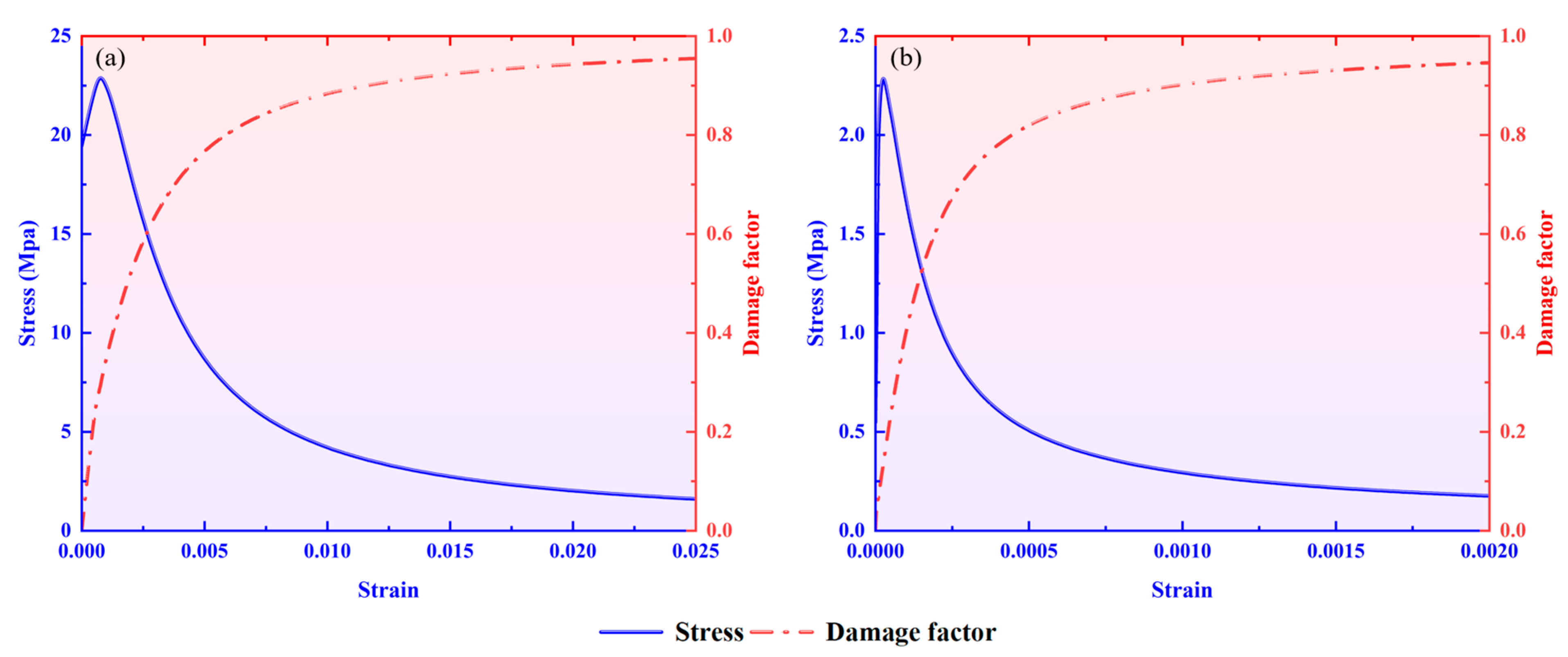
In the process of accurately simulating the response of a tunnel during fault displacement, the key lies in whether the interactions between different structural components can be accurately characterized. Based on this, this paper adopts a refined modeling strategy for the interface and material constitutive relations. For the rock mass (hanging wall and footwall) and the fault fracture zone, the ideal elastoplastic Mohr–Coulomb criterion is used for simulation. Its physical and mechanical parameters (see Table 1 [37] for details) are carefully calibrated according to laboratory data to ensure the authenticity and reliability of the geotechnical parameters. The tunnel lining system consists of inner and outer layers. When conducting numerical simulation tasks, building a precise model is a fundamental requirement for attaining accurate simulation results. It is essential to comprehensively take into account the interaction between soil and structure. Special attention should be paid to the interface behavior [38]. The outer lining and the surrounding rock are subjected to a “bonded” constraint to simulate the coordinated deformation state formed after the drill-and-blast construction method. Particularly crucial is that a contact surface mechanical model is used to simulate the mechanical interaction between the inner and outer linings. This interface modeling method is crucial for capturing discontinuous deformation phenomena such as sliding and separation that may occur during fault displacement, and these discontinuous deformations are the key mechanisms of tunnel failure. In the contact model, a “hard” contact is adopted in the normal direction to prevent unrealistic mutual intrusion. The tangential behavior is controlled by the Coulomb friction law and implemented through the penalty function method. This method can realistically simulate the shear stress transfer process of the interface before reaching the shear strength, and then relative sliding occurs. This mechanism is of great significance for accurately analyzing the internal force distribution of the lining and determining the position of the critical section. The selection of the friction coefficient is carefully considered to ensure its physical authenticity based on authoritative literature. Among them, the friction coefficient between the inner and outer linings is taken as 0.4 [39], which represents a typical value for the concrete–concrete interface. For the fault displacement interface between the hanging wall/footwall and the fault fracture zone, the friction coefficient is taken as 0.6 [40]. This value is consistent with the description of rock–rock friction in Byerlee’s law [41] and also reflects the characteristics of the fault fracture zone. The accurate determination of these parameters is of great significance for ensuring the reliability of simulating fault rupture propagation and soil-structure interaction. The concrete damage plasticity model is used for tunnel lining to describe its inelastic behavior under tensile and compressive stresses. Its stress–strain curve is shown in Figure 2, and the relevant parameters are listed in Table 2. To ensure the accuracy of the simulation results, a mesh sensitivity analysis was conducted in this study. The maximum stress values were calculated for meshes of 1 m, 0.75 m, and 0.5 m in size, which were 9.79 × 10⁶, 1.152 × 10⁷, and 1.191 × 10⁷ respectively. The calculation results of the 0.75 m mesh and the 0.5 m mesh differed by less than 5%. Therefore, a mesh width of 0.5 m was adopted within ±30 m from the center of the fault fracture zone. The final model consists of 44,560 eight-node reduced integration hexahedral elements and 60,126 nodes. A fine mesh is used around the tunnel and fault fracture zone areas to capture high stress and strain gradients. Meanwhile, a coarser mesh is adopted in the far-field rock mass area to improve the calculation efficiency. This meshing strategy effectively balances the calculation cost and the need to analyze local deformation patterns.

2.3. Simulation Process

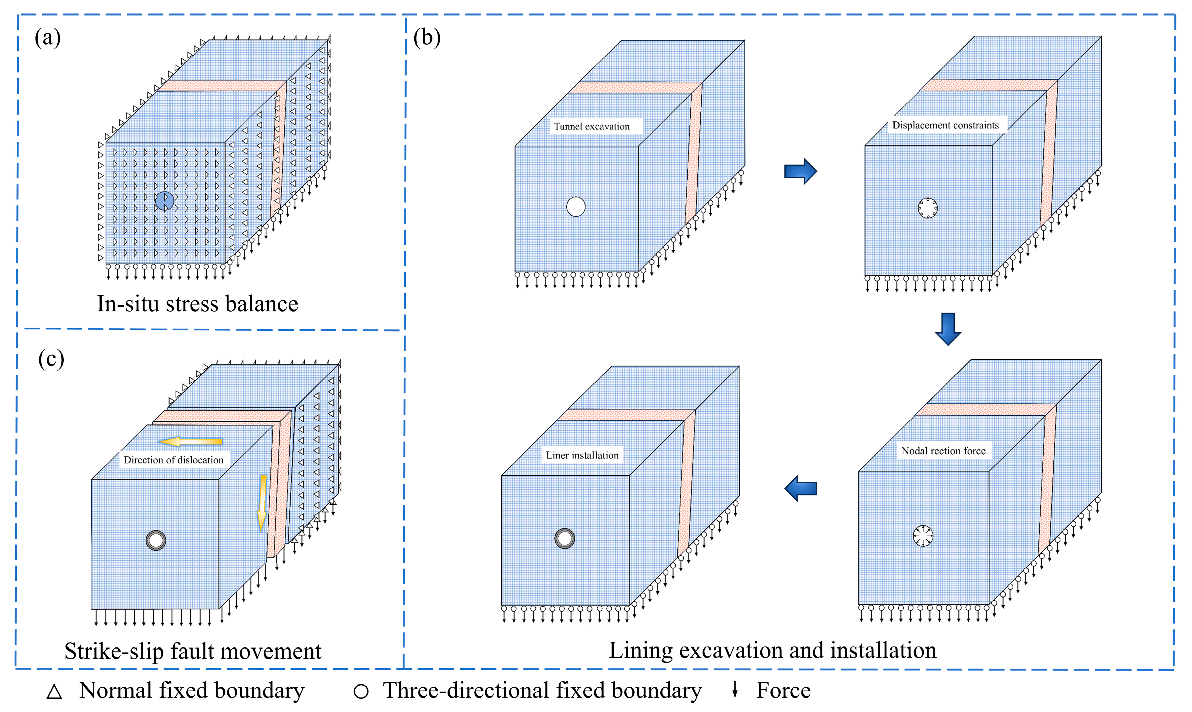
The simulation steps of the oblique-slip fault displacement process are as follows: 1. Apply gravity to the free-field model and then carry out the in situ stress equilibrium operation to obtain the initial stress state of the free field; 2. Use the convergence-confinement method to simulate the tunnel construction; 3. Fix the footwall and apply a forced displacement to the hanging wall along the displacement direction in a quasi-static manner. In the course of tunnel excavation, to avoid the surrounding rock load from acting on the lining structure and resulting in certain elastic deformations of the lining, the softened modulus method and the convergence-confinement method are the two most frequently employed approaches for current tunnel excavation [42,43]. Compared with the softened modulus method, the convergence-confinement method can simulate the time effect and support sequence in actual construction by gradually releasing the stress on the excavation boundary. Therefore, the convergence-confinement method is selected for the tunnel excavation process. Considering that the occurrence of fault displacement usually has a long time interval from the tunnel excavation time, it is assumed that the tunnel is excavated instantaneously from one side of the rock mass to the other side. When actually carrying out construction work, the step-by-step excavation method will cause a certain degree of stress release and stress redistribution of the surrounding rock before the lining is supported. As a result, the initial stress state borne by the lining is different from that under the condition of instantaneous support. However, this research focuses on the response of the tunnel under the extremely special structural load of strong fault dislocation. Under such working conditions, the large deformation and secondary stress caused by fault dislocation have a much greater impact than the initial stress differences caused by different excavation sequences. At this time, the factors generated by fault dislocation have become the key dominant factors determining the damage mode and stability of the tunnel. In view of this, the method of instantaneous excavation assumption can be used to efficiently construct a clear and definite benchmark analysis model. With the help of this model, the research can focus on the core mechanical mechanism of fault dislocation and then conduct in-depth related research. The tunnel excavation process typically consists of 4 consecutive loading steps, as depicted in Figure 3. Initially, the birth–death element method is employed to render the primary support and secondary lining ineffective. Then, apply gravity to the free-field model to obtain the initial stress field. Next, simultaneously “kill” the soil mass to be excavated inside the tunnel and apply displacement constraints to the excavated tunnel wall. Finally, after removing the soil mass inside the tunnel, extract the initial support reaction force at the tunnel wall from the calculation results. While releasing the node displacement constraint, apply this support reaction force to the corresponding nodes to ensure that the remaining displacement maintains the same equilibrium state. According to the “Code for Design of Highway Tunnels” (Ministry of Transport of the People’s Republic of China, 2010) [44], reduce the support reaction force to half of its initial value. This is to simulate the stress release process that occurs during tunnel excavation. Eventually, the lining is activated, and the remaining support reaction force is released until it reaches zero. To simulate the movement of a left-lateral normal fault, as shown in Figure 3c, a uniform three-dimensional displacement parallel to the fault plane is applied to the nodes on the outer surface of the moving block. It is assumed that the dislocation occurs at the junction of the hanging wall, the footwall, and the fractured zone [45]. In addition, normal motion constraints are applied to both the side and bottom of the fixed block boundary.

2.4. Verification

To confirm the effectiveness of the simulation approach, modeling tasks were conducted for the tunnels damaged during the Kumamoto Earthquake. After that, the simulation outcomes were compared with and verified against the damaged structures in the Kumamoto Earthquake. Figure 4 presents the comparison between the simulation results and the damaged tunnels in the Kumamoto Earthquake. After the tunnel misalignment was completed, significant compressive damage occurred in the vault area of the tunnel, as shown in Figure 4a. This damage induced excessive deformation of the secondary lining (Figure 4b), which in turn triggered the local collapse of the vault in the tunnel section passing through the fault fracture zone.

3. Result Analysis

A three-dimensional numerical model was developed for the Xianglushan Tunnel of the Central Yunnan Water Diversion Project to analyze the damage induced by oblique-slip faults. Based on the geological exploration data of the Heqing–Eryuan Fault Zone, studies indicate that since the late Pleistocene, the main fault within the basin section has experienced a maximum vertical displacement rate of 0.4 mm/a and a maximum horizontal strike-slip rate of 2.0 mm/a. Therefore, according to the displacement amount for a 100-year prevention standard, the horizontal displacement of 0.2 m and the vertical displacement of 0.04 m were set as the basic working conditions [47].

3.1. The Deformation Response Mechanism of Tunnels to the Displacement of Oblique-Slip Faults

As depicted in Figure 5, it demonstrates the displacement nephogram of the tunnel subsequent to the imposition of forced displacement on the active disk. Analysis of Figure 6 indicates that fault displacement induces significant horizontal and longitudinal deformation in the tunnel, manifesting as a distinct spatial “S”-shaped pattern. In both the active disk and the fixed disk, the displacements of the tunnel at different positions are identical. Specifically, in the region of the active disk distant from the sliding surface, the displacement of the lining attains the maximum value, whereas the displacement of the tunnel in the fixed disk area is nearly negligible.
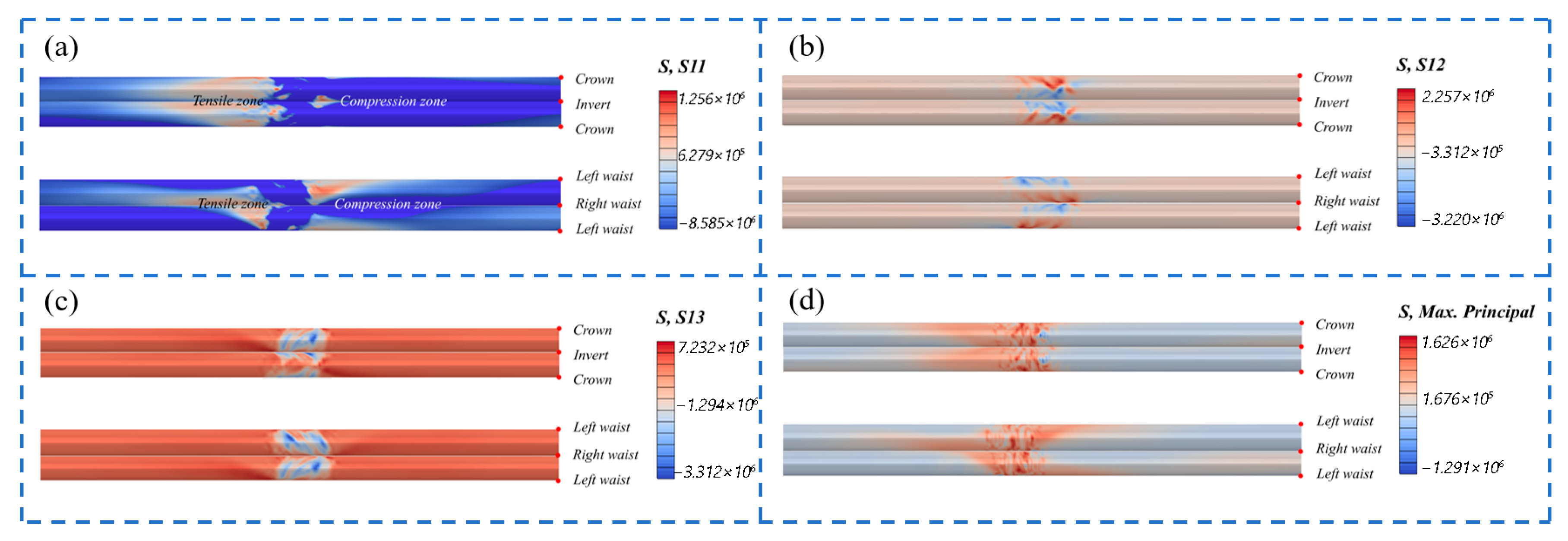
When the tunnel passes through the fault, the deformation shows transitional changes. The research findings further indicate that for a normal fault, the displacements of the hanging wall and the footwall mainly take the form of asymmetric tension. In contrast, for a strike-slip fault, the displacements of the hanging wall and the footwall display characteristic shear phenomena. Figure 6 presents the distribution nephograms of the axial stress, axial shear stress, and maximum principal stress of the tunnel subsequent to fault displacement. It is evident that stress concentration takes place at the junction of the hanging wall, footwall, and fault fracture zone of the tunnel as a result of fault displacement. Using the fault displacement surface as the interface, it can be clearly discerned that there are tensile and compressive regions on the sides, top, and bottom of the tunnel. Specifically, the maximum tensile stress amounts to 1.26 MPa, and the maximum compressive stress is 8.59 MPa. The maximum value of the vertical shear stress is −3.22 MPa, and the maximum principal stress is −1.63 MPa. It is noteworthy that all these intense stress states are distributed along the fault displacement surface.

3.2. Influence of Different Fault Displacement Forms on Tunnels

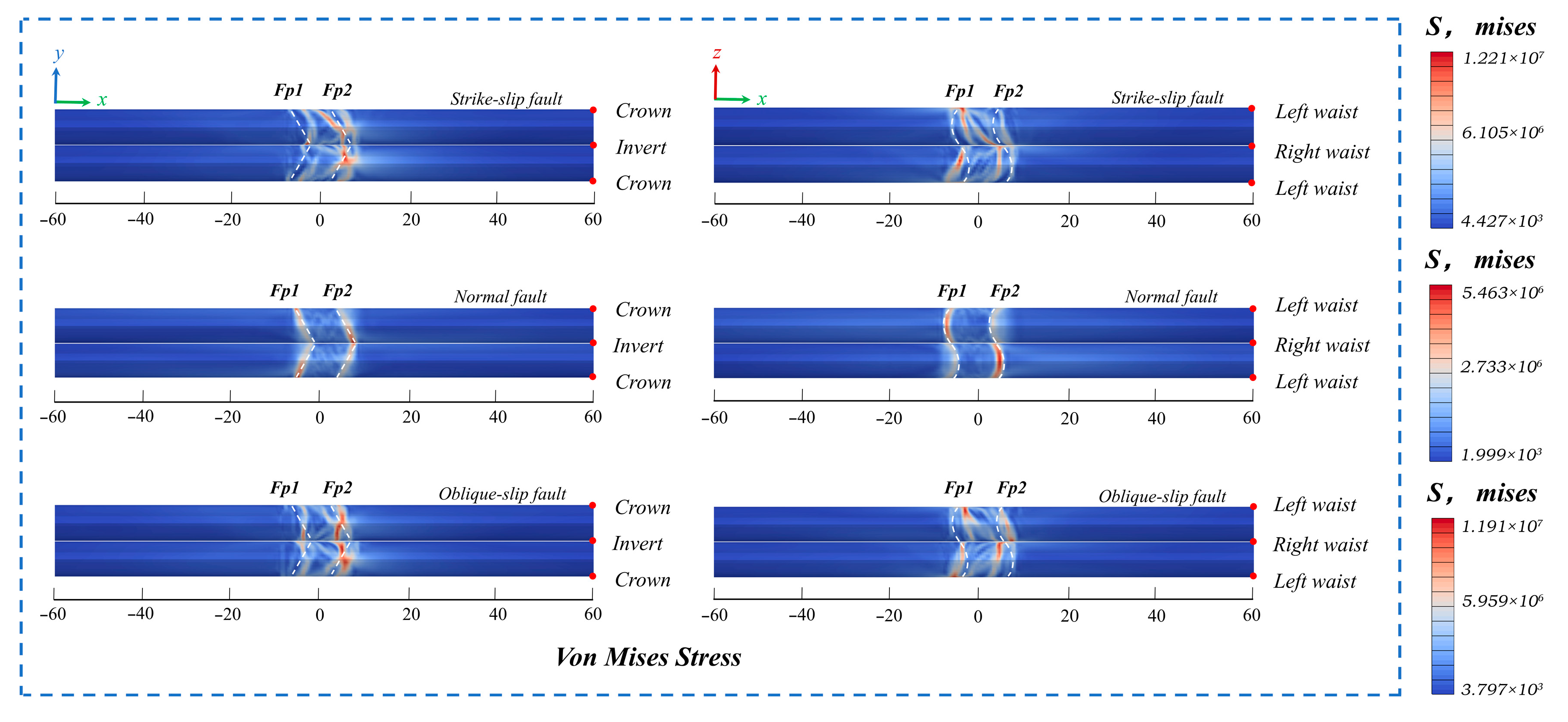
The displacement direction of an oblique-slip fault is jointly determined by a strike-slip fault that displaces horizontally and a normal fault that displaces along the fault direction. To compare the impacts of oblique-slip faults, single strike-slip faults, and normal faults on tunnels, this paper constructs numerical models of tunnels crossing oblique-slip faults, strike-slip faults, and normal faults. Figure 7 shows the Mises stress nephograms of tunnels crossing oblique-slip faults, strike-slip faults, and normal faults, respectively.
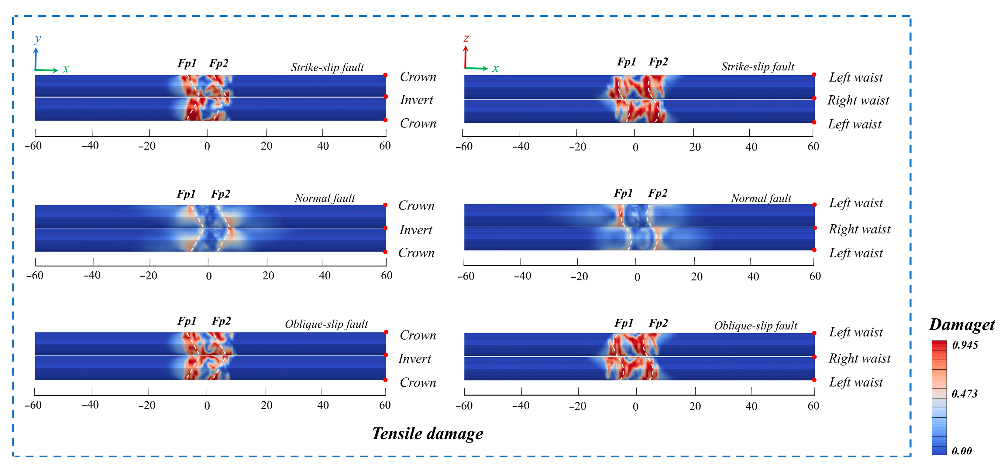
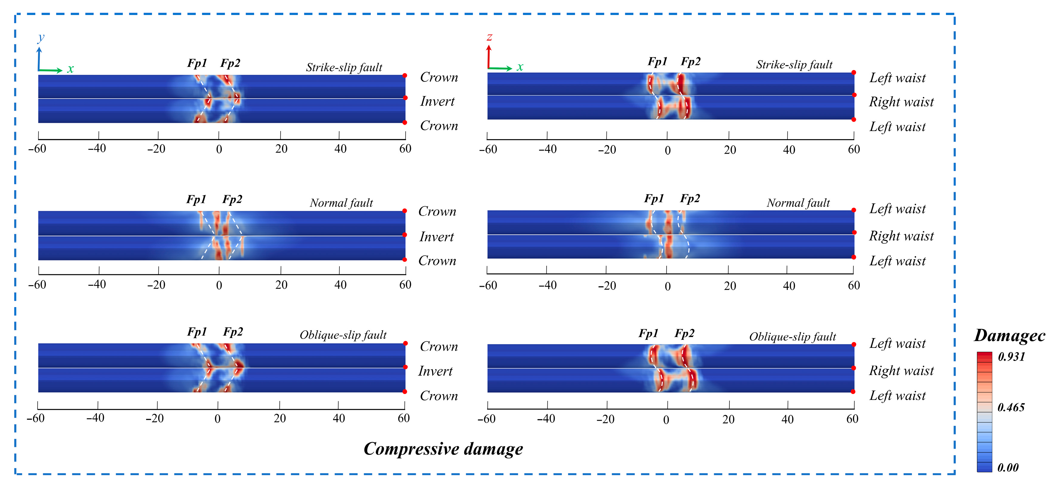
As shown in Figure 7, the maximum Mises stress induced by the strike-slip fault reaches 12.27 MPa. In contrast, under the influence of oblique-slip faults, the maximum value of this stress is 11.91 MPa. As presented in Figure 8 and Figure 9, the tensile and compressive failure ranges of the tunnel induced by strike-slip faults are notably larger than those under the action of oblique-slip faults.
Therefore, it is evident that tunnels traversing strike-slip faults are more severely affected. Even though the behavior of oblique-slip faults is the combination of the movements of normal faults and strike-slip faults, in comparison with strike-slip faults, the impact of the displacement of oblique-slip faults on the stress magnitude and damage extent of the tunnel is relatively minor. The underlying mechanism of this phenomenon can be clarified by conducting a comprehensive analysis of fault kinematics and structural responses. The motion of an oblique-slip fault can be broken down into a strike-slip part and a dip-slip (normal fault) part. Even though the overall displacement vector of an oblique-slip fault may be greater, its influence on linear tunnel structures is more spread out, and some of the effects offset one another. Regarding kinematic effects and stress conditions: The dominant horizontal shearing effect of a strike-slip fault exerts continuous longitudinal bending moments and shear forces over a significant length along the tunnel axis. This results in a severe combined stress condition (bending-shear) in the entire tunnel lining, causing extensive damage. Conversely, the dip-slip component of an oblique-slip fault is mainly manifested as local vertical displacements across the fault. This action frequently leads to more local “kinks” or axial compression/tension in the tunnel. For this kind of stress state, the continuous lining structure has a relatively high resistance ability. Inherent structural vulnerabilities: As a slender underground structure, the tunnel lining inherently has a relatively lower resistance ability against shear and bending stresses compared to axial stresses. The tensile strength of concrete is much lower than its compressive strength, and oblique shear cracks induced by shear forces are particularly detrimental to the structural integrity. The strike-slip fault exacerbates this vulnerability directly by imposing a deformation mode mainly characterized by shear and bending. Damage development: Under the influence of a strike-slip fault, the damage is not confined to the immediate fault zone but spreads along the tunnel axis, resulting in the “significantly larger” damage scope shown in Figure 8 and Figure 9. In the case of an oblique-slip fault, the damage is more concentrated at the fault intersection. This is because the damage energy is dissipated through a combination of local bending and axial deformation, and this form is less effective in triggering continuous and progressive collapse. In summary, the deformation patterns (shear and longitudinal bending) induced by a strike-slip fault are the least structurally advantageous for tunnels, which may lead to extensive and continuous damage. Although the vector displacement of an oblique-slip fault is larger, it gives rise to a mixed deformation pattern. Additionally, a significant portion of the energy is dissipated in a less damaging way (local compression/tension), thereby resulting in relatively less severe consequences.
It should be pointed out, though, that as a tectonic form that exists extensively in seismically active regions around the world, for mountain tunnels with limited alignment options, the inevitability of oblique-slip faults is significantly higher than that of the idealized single strike-slip fault. If the differences in such faults are ignored in engineering design and all designs are carried out according to strike-slip faults with greater damage degree, it is very likely to lead to deviations in the risk assessment of key engineering nodes, resulting in distorted assessment results. At the same time, it may also lead to overly conservative designs, thus causing waste of resources. Therefore, in-depth research on composite faults is of crucial significance for optimizing the allocation of engineering resources and enhancing the overall resilience of the project. It can not only ensure the safety of the project but also take into account the economy, achieving the maximization of engineering benefits.

4. Parameter Sensitivity Analysis

This study employed a numerical model to investigate the influence of fault displacement, width, and dip angle on the tunnel’s response to an oblique-slip fault. The details of the corresponding simulation cases are shown in Table 3, and the form of fault movement is presented as shown in Figure 10. In addition, three monitoring surfaces were carefully set at the fault slip surface and the center position of the fault fracture zone, which were marked as S1, S2, and S3, respectively.

4.1. Influence of Fault Dislocation Distance

In the mechanism of oblique-slip faults, the strike-slip component is dominant, and the vertical component is secondary. This makes the main direction of movement point from the right arch shoulder to the left arch foot. Therefore, the characteristic of the diagonal deformation pattern of the tunnel cross-section is reflected in the relative displacement between these two points. Consequently, the oblique tunnel diameter deformation rate D is used to analyze the deformation pattern of the tunnel section under the condition of fault displacement. Herein, the oblique tunnel diameter deformation rate D is defined as:
D = 1 − Δd/d
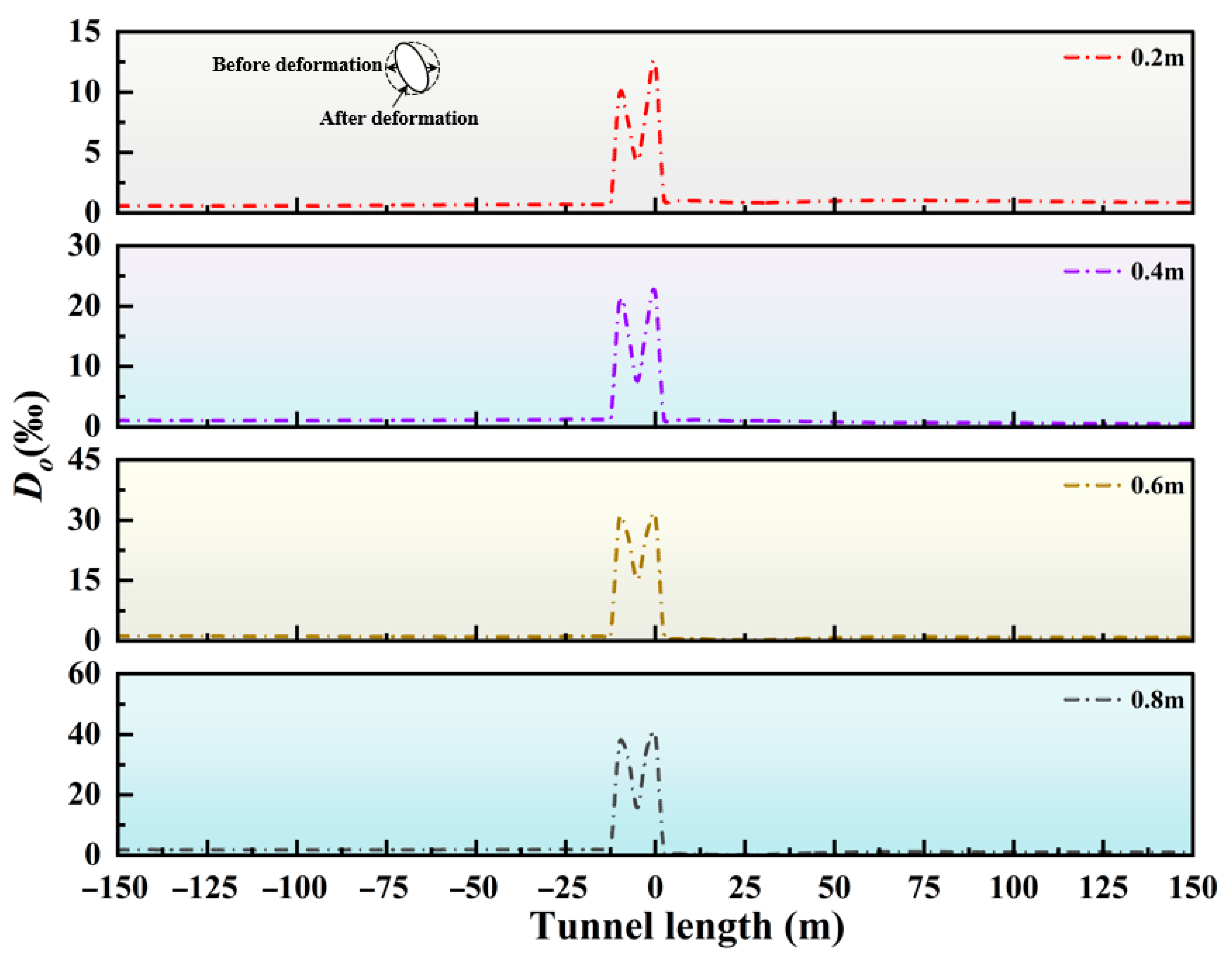
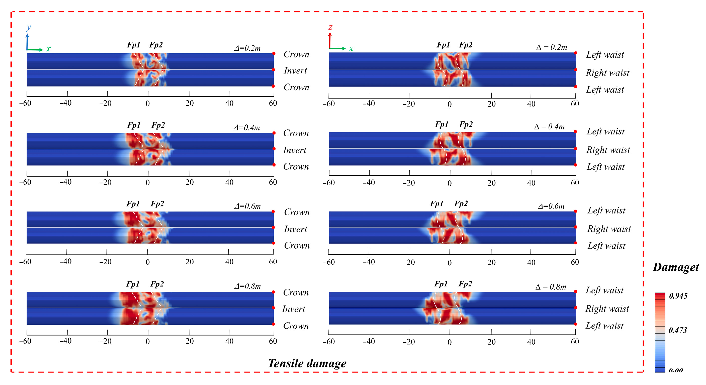
In the formula, Δd represents the relative displacement between two points, and d is the diameter of the secondary lining. Figure 11 shows the oblique deformation curve of the tunnel section. As can be discerned from the figure, as the displacement increases, the deformation of the tunnel section at the fault slip surface becomes increasingly prominent. This phenomenon can be attributed to the growth of the oblique shear force resulting from the increase in the displacement of the oblique-slip fault. Figure 12 and Figure 13 show the tensile and compressive failure nephograms of the tunnel under different displacement values. It can be noted that the damage to the tunnel is mainly concentrated at the two fault slip surfaces, and the damage scope gradually expands as the displacement amplitude increases. The damage to the right arch shoulder is more severe than that to the right arch waist. This is because the relative movement pattern of the hanging wall and the footwall is an oblique movement from the upper right to the lower left, and the shear force exerted by the active disk on the arch shoulder is greater than that on the arch waist.
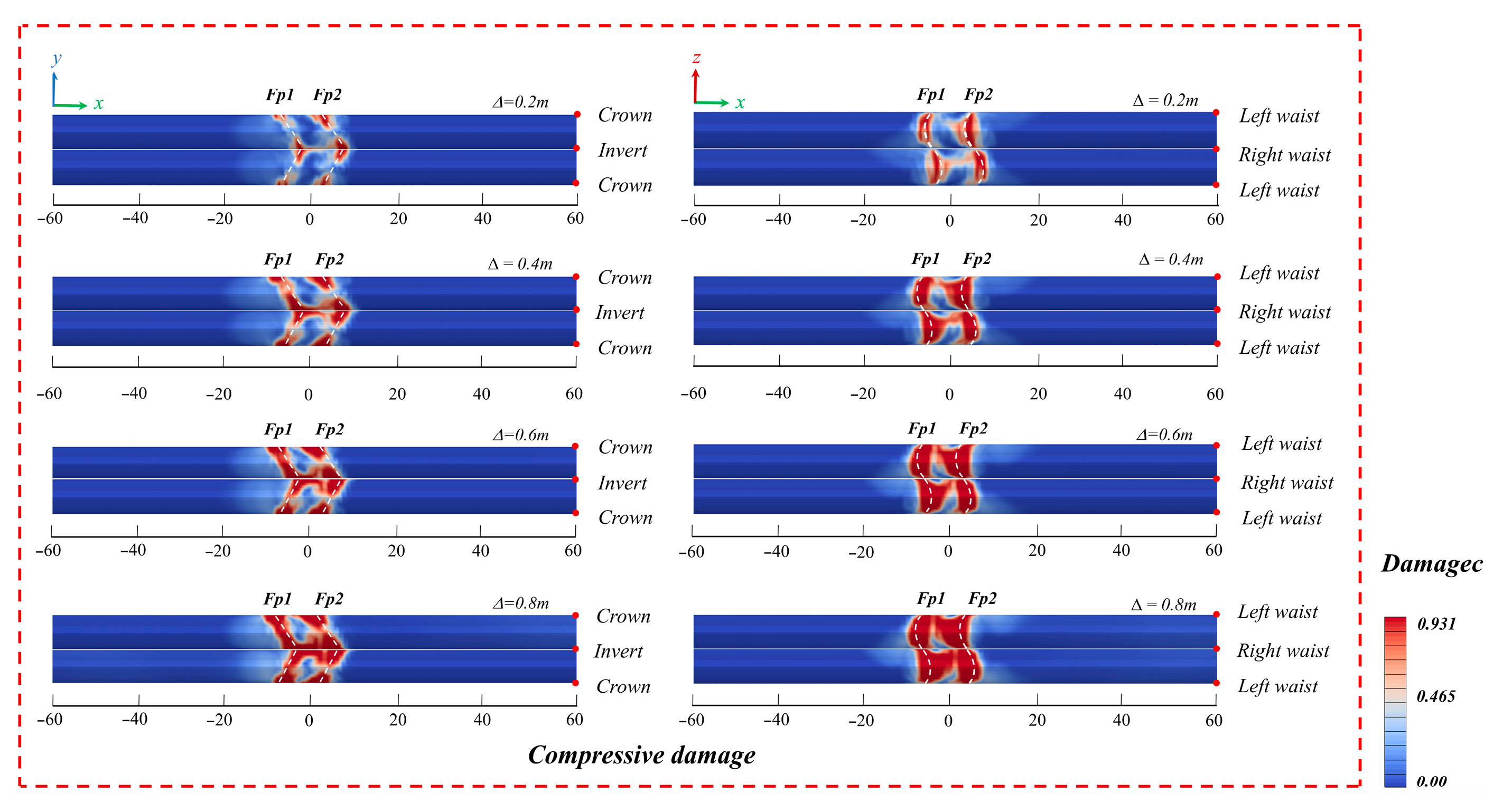
As depicted in Figure 12 and Figure 13, the tensile and compressive failure nephograms of the tunnel under various fault displacement conditions are presented. The research indicates that the failure manifestations of the tunnel are predominantly concentrated in the two faults slip surface areas. With the increase in fault displacement, the damage range shows a tendency to gradually expand and intensify. Further analysis reveals that the damage degree of the right arch shoulder is more serious than that of the right arch waist. The reason for this phenomenon is that the relative movement pattern of the fixed disk and the move disk is an oblique movement from the upper right to the lower left. During this process, the shear force exerted by the active disk on the arch shoulder is significantly larger than that on the arch waist. At position FP1, the left tunnel wall is in tension and the right wall undergoes compression. In contrast, this stress state is completely reversed at FP2. Specifically, when the displacement is 0.2 m, the compressive damage degree at FP2 is greater than that at FP1; when the displacement reaches 0.4 m, the compressive damage observed at FP1 starts to gradually increase; when the displacement reaches 0.8 m, the compressive damage degree at FP1 is more notable than that at FP2. This is primarily due to the fact that as the fault displacement keeps increasing, the displacement gradually shifts from the upper plate of the fault to the lower one. Moreover, the oblique failure phenomena that occur at the crown and the invert of the middle structure within the fault fracture zone are the result of the combined effect of the tensile and compressive complex stress conditions produced by the relative movement of the hanging wall and the footwall in the central region of the fault fracture zone. These results demonstrate that the tunnel’s deformation and failure are primarily concentrated at the fault plane and along its contact with the surrounding rock.
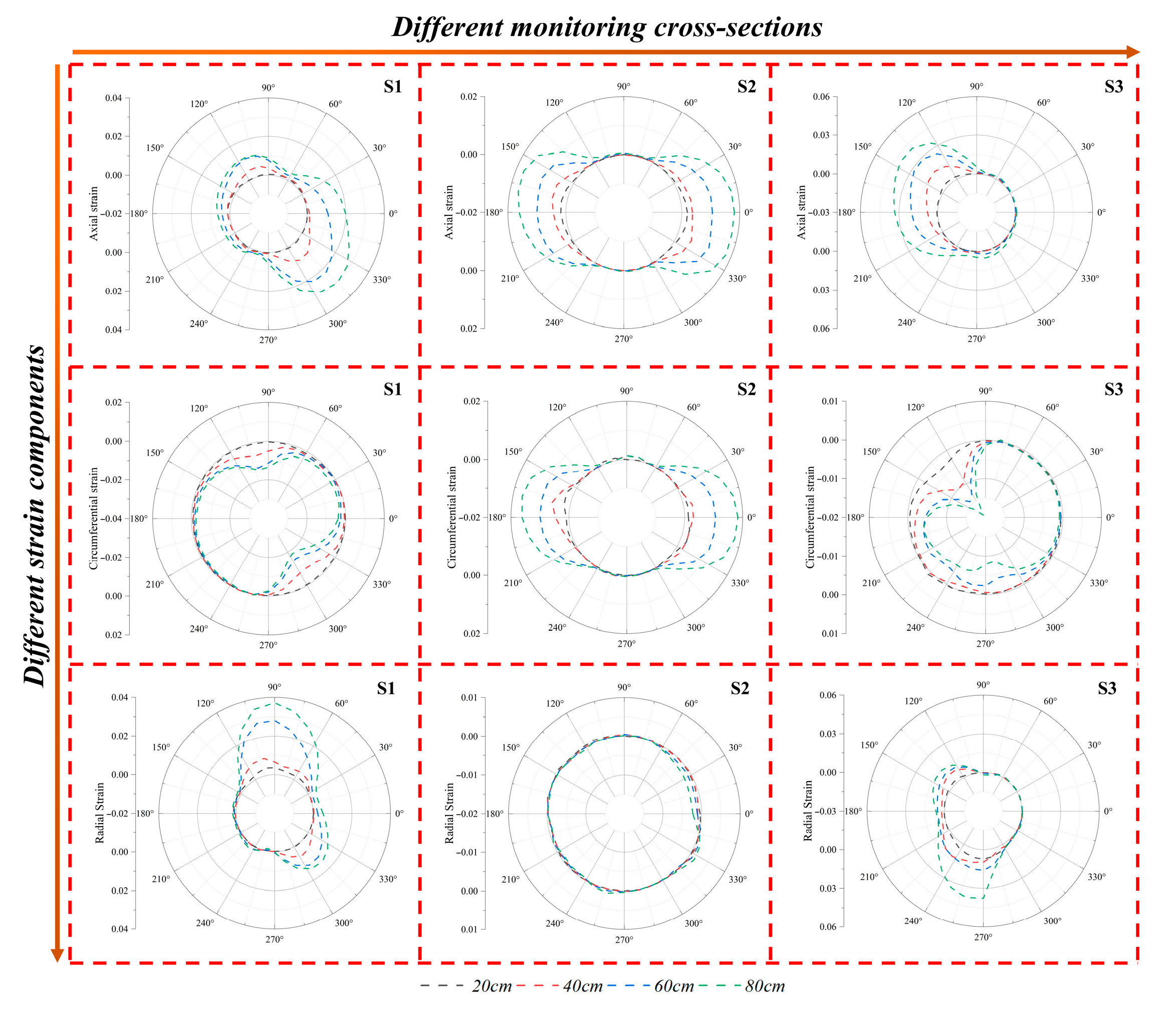
Figure 14 presents additional information regarding the strain distribution of sections S1, S2, and S3 of the tunnel in the vicinity of FP1 and FP2 under various fault displacement conditions. This outcome visually illustrates the tunnel’s deformation pattern. As a key indicator, the axial strain reflects longitudinal tensile and compressive behavior. Similarly, the circumferential and radial strains characterize the cross-sectional deformation. Generally, the stress concentration phenomenon mainly occurs at sections S1 and S3 and is significantly influenced by the fault displacement. The influence of fault displacement variation is more pronounced on the deformation of sections S1 and S3 than on the overall deformation amplitude of section S2. Specifically, all strain components exhibit an increasing trend with greater fault displacement. At section S1, the left arch waist and right arch shoulder experience distinct axial tension; similarly, circumferential compression is found at the right arch shoulder and the left arch springing. Conversely, at section S3, prominent axial tension occurs in the right arch waist and left arch springing, whereas compression concentrates at the left arch shoulder. For section S2, the main deformation pattern is the radial and circumferential tension along the crown and the invert. Moreover, the axial strain of section S2 shows little sensitivity to the increase in displacement.

4.2. Influence of Fault Dip Angle

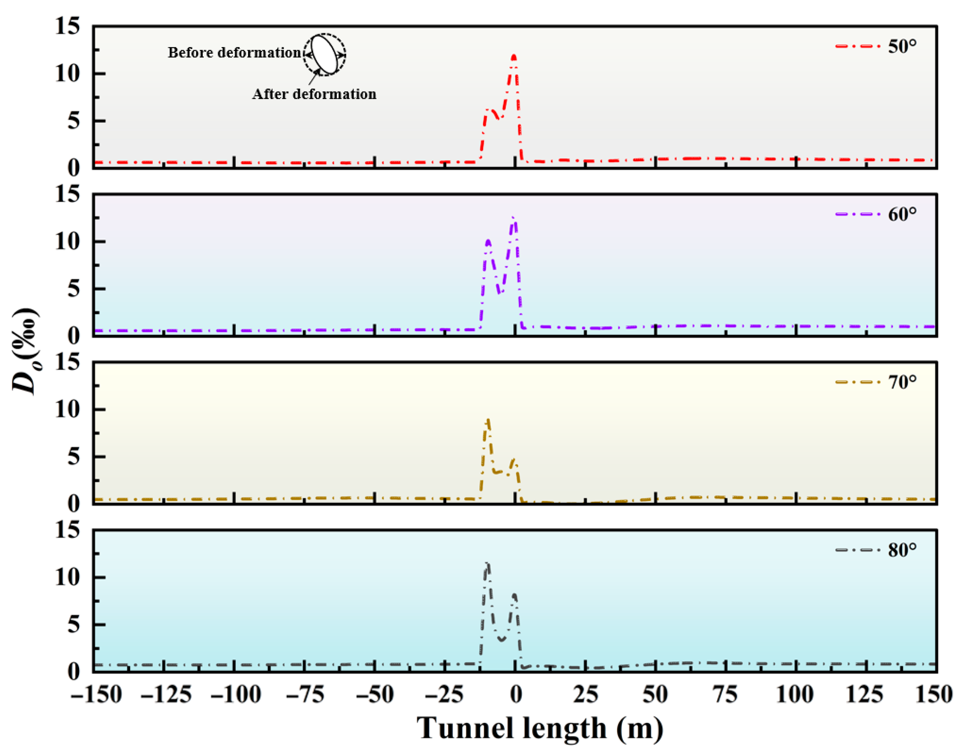
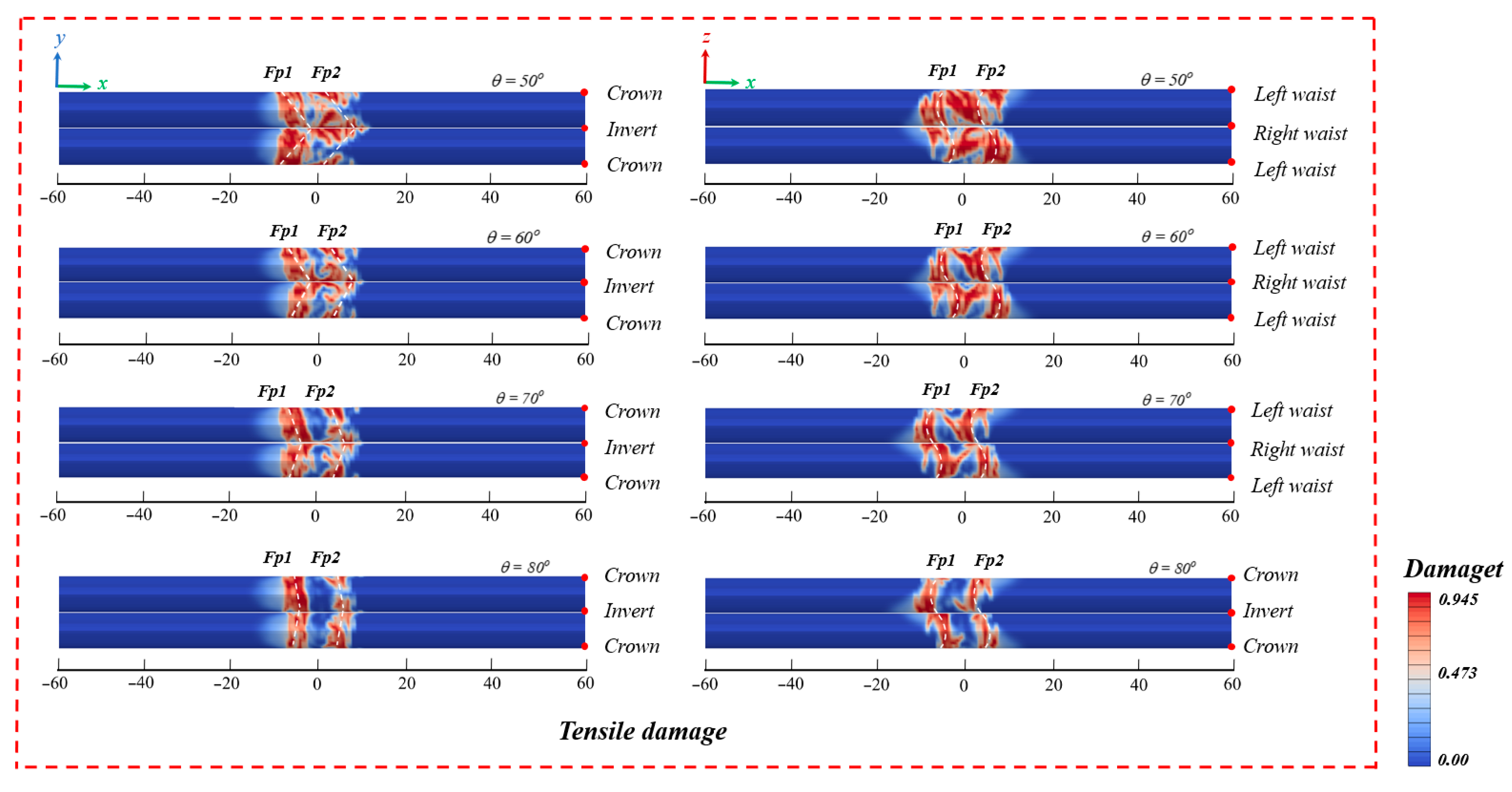
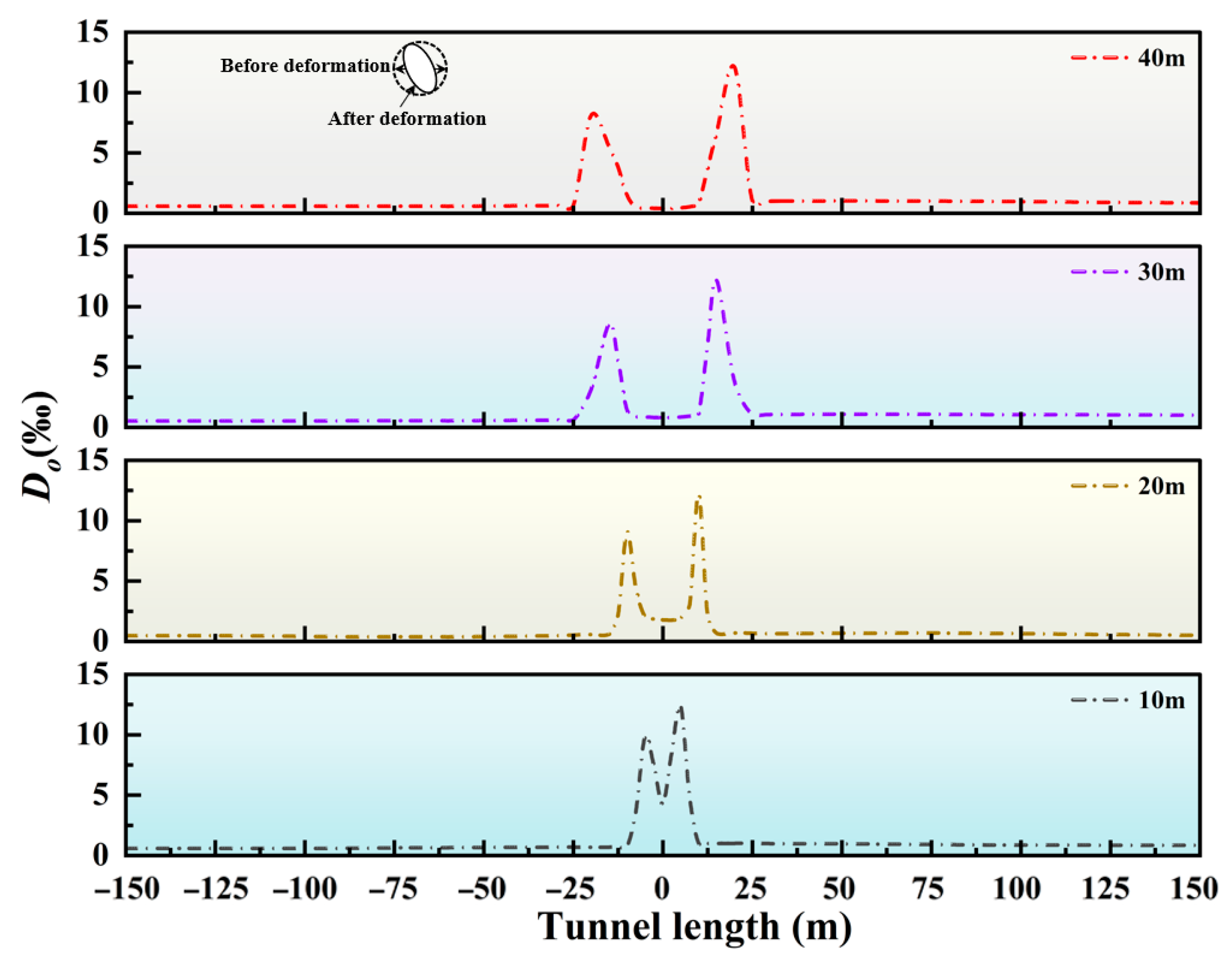
As depicted in Figure 15, this figure shows the variation curves of the deformation rate of the tunnel’s oblique diameter under different fault dip angles. Evidently, the deformation of the tunnel cross-section reaches an extreme value at the location of the fault slip surface. It is important to note that as the fault dip angle keeps increasing, the maximum value of the cross-sectional deformation gradually moves from the interface between the hanging wall and the fault fracture zone initially to the interface between the footwall and the fault fracture zone. This phenomenon primarily results from the coupling between strike-slip and normal faulting on this particular structure. Under the influence of normal faults, as the fault dip angle gradually increases, the shear stress component of gravity acting on the fault fracture zone increases significantly. This, in turn, facilitates more significant slip within the fault fracture zone, thereby inducing greater distortion of the tunnel cross-section at the footwall interface.
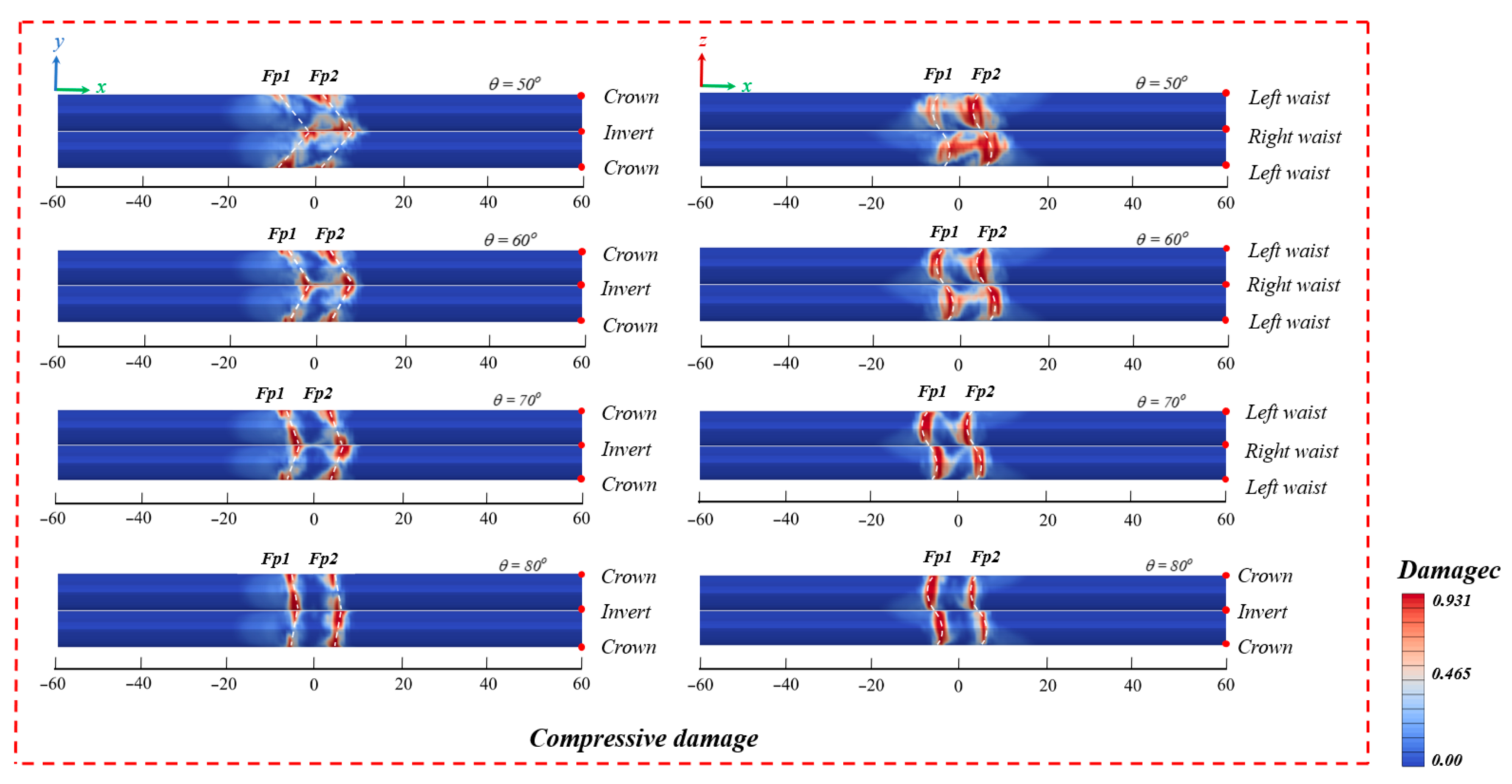
Figure 16 and Figure 17 present the failure outcomes of the tunnel under various fault dip angles. By analyzing these results, it is evident that the damage of the tunnel is predominantly concentrated at the fault slip surface. Meanwhile, oblique tensile and compressive damages occur at the vault and the invert of the middle structure within the fault fracture zone. As the fault dip angle increases, the damage area at the fault slip surface gradually decreases. Moreover, the distribution of tensile and compressive damages on either side of the tunnel shows asymmetry, and the extent of damage spreading towards the center of the fault fracture zone also becomes smaller. This is because as the fault dip angle increases, the failure mode of the tunnel gradually shifts from tensile–compressive combined failure to tensile–shear combined failure. When the fault dip angle is small, the horizontal component of the fault movement force is substantial and its influence range is extensive. On the contrary, as the dip angle increases, the coupling effect between axial tension and local shear becomes stronger, resulting in more concentrated deformation. To sum up, during the design of cross-fault tunnels, to effectively prevent large-scale damage to the tunnel, the tunnel should cross the fault at the largest possible angle.
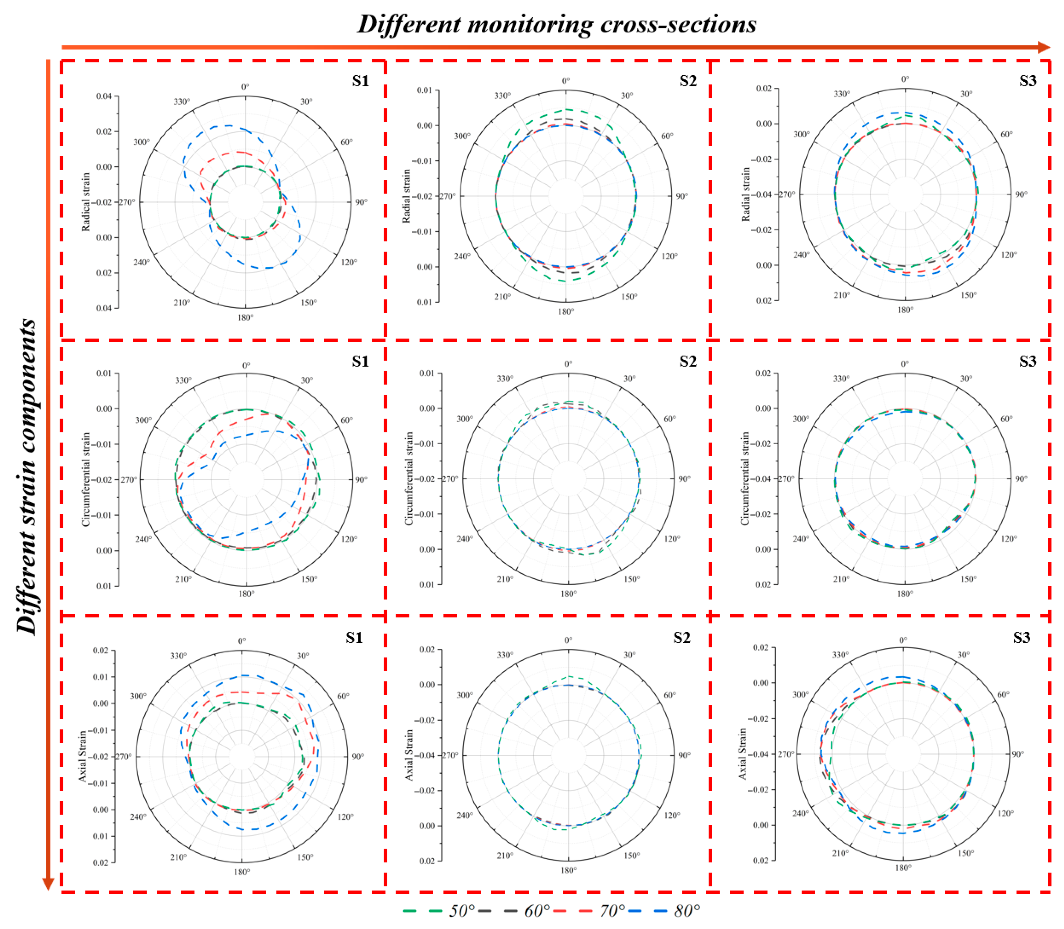
Figure 18 shows how the strain distribution at three monitoring sections of the tunnel changes with the variation in the fault dip angle. The fault dip angle has a negligible impact on various strains of S2. At S1, the circumferential strain mainly shows an oblique tensile deformation, which is more prominent in the region from the left arch shoulder to the right arch springing. The radial strain shows tensile deformation on both the upper and lower sides. Except for the right arch springing, tensile phenomena exist throughout the axial strain, and as the dip angle increases, it will cause a moderate change in deformation. At S3, while increases in the fault dip angle cause negligible changes in most deformation metrics, a notable exception is the radial strain. Additionally, axial tensile deformation emerges at the right waist.

4.3. Influence of the Width of the Fault Fracture Zone

When the width of the fractured zone is considerably smaller than the tunnel diameter (10 m), the mechanical behavior approximates that of an isolated weak interlayer or a large structural joint. Under such conditions, tunnel stability is governed primarily by the positional relationship between the tunnel and the weak interlayer, rather than by the absolute width of the fractured zone. The key range examined in this study (10–40 m) represents one of the most common and challenging scenarios in tunnel engineering. This width, ranging from 1 to 4 times the tunnel diameter, is sufficient to fully envelop the tunnel within a distinct weak zone, yet it does not necessitate a fundamental change in construction method (e.g., switching to mining methods or specialized techniques). Within this range, investigating how variations in the width of the fractured zone influence surrounding rock stress, deformation, and support requirements offers considerable practical significance. When the width of the fractured zone substantially exceeds the tunnel diameter (e.g., >4D), the engineering problem transitions in nature. In such cases, the tunnel can be considered as situated entirely within a homogeneous—or gradually varying—weak rock mass. At this scale, stability becomes largely insensitive to minor changes in the width of the fractured zone and is instead controlled by the overall mechanical properties of the weak rock mass. Therefore, a fractured zone width of 10–40 m has been selected for detailed analysis in this study. Figure 19 plots the tunnel’s oblique diameter deformation rate against fault displacement. When the fault width expands from 10 cm to 40 cm, the oblique diameter change rate at FP1 drops from 9.8‰ to 8.1‰, showing a decrease of approximately 17%. With increasing fault width, the cross-sectional deformation amplitude at FP2 is larger than that at FP1. The reason for this is that when the fault moves, the hanging wall moves away from the fixed boundary, thus having a greater degree of movement freedom. Due to its overall movement characteristics, this kind of deformation can affect a larger area. Therefore, it is less sensitive to the change in the width of the fault fracture zone. On the contrary, during fault movement, the footwall is more strongly restricted, and the deformation is confined to the vicinity of the fault. Therefore, it is highly sensitive to the width of the fault fracture zone.
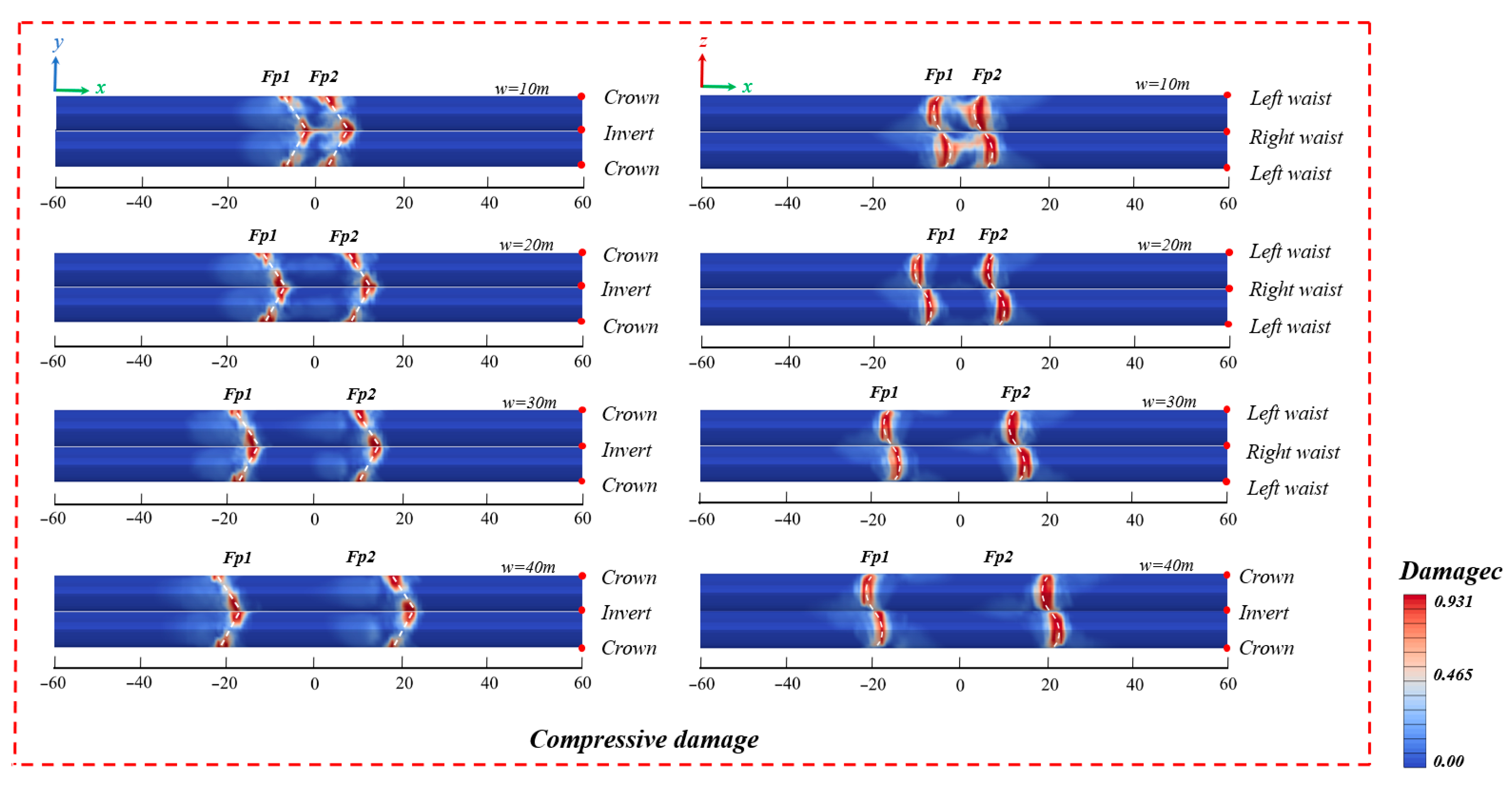
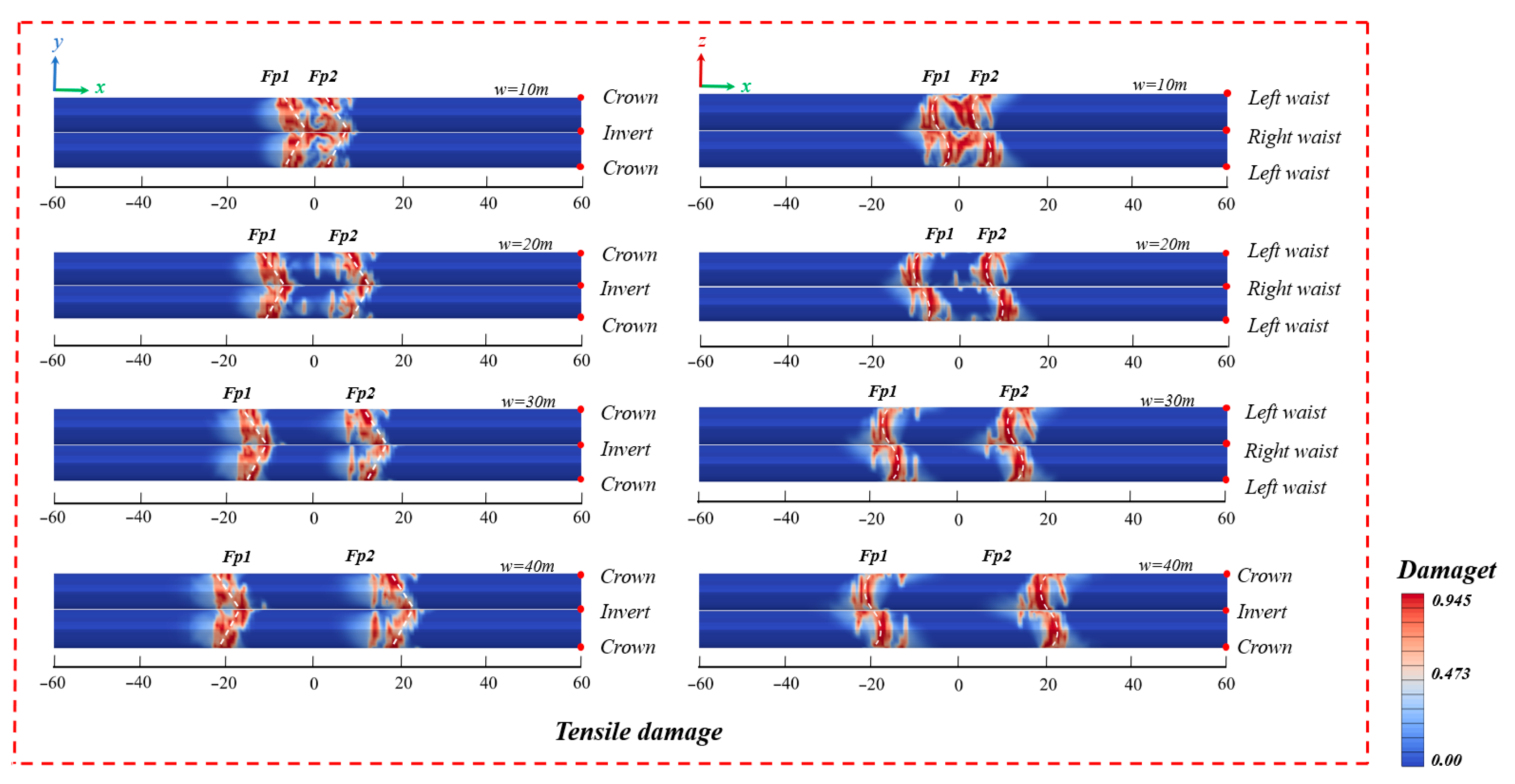
Figure 20 and Figure 21 illustrate the tensile and compressive failure conditions of the tunnel under different fault fracture zone widths. It can be observed that there are distinct tensile and compressive failure phenomena at the slip surface. A relatively small fault width leads to severe tensile–compressive composite damage within the fault fracture zone. This damage primarily manifests as axial failures at both the vault and the invert of the tunnel. With the increase in the width of the fault fracture zone, the damage at the slip surface reduces significantly. However, the damage range gradually expands from the junction of the footwall and the fault fracture zone towards the footwall. This mechanism can be explained as follows: When a tunnel traverses a wide fault fracture zone, its damage mechanism transforms from the “concentrated shear failure” of a narrow fault fracture zone to “distributed bending failure”. The steep rock mass in the footwall has high resistance to deformation. This causes the internal force to spread from the interface into the footwall, thereby forming a large-scale damage zone. The wider the fault fracture zone is, the greater the space required for the transfer and release of force.
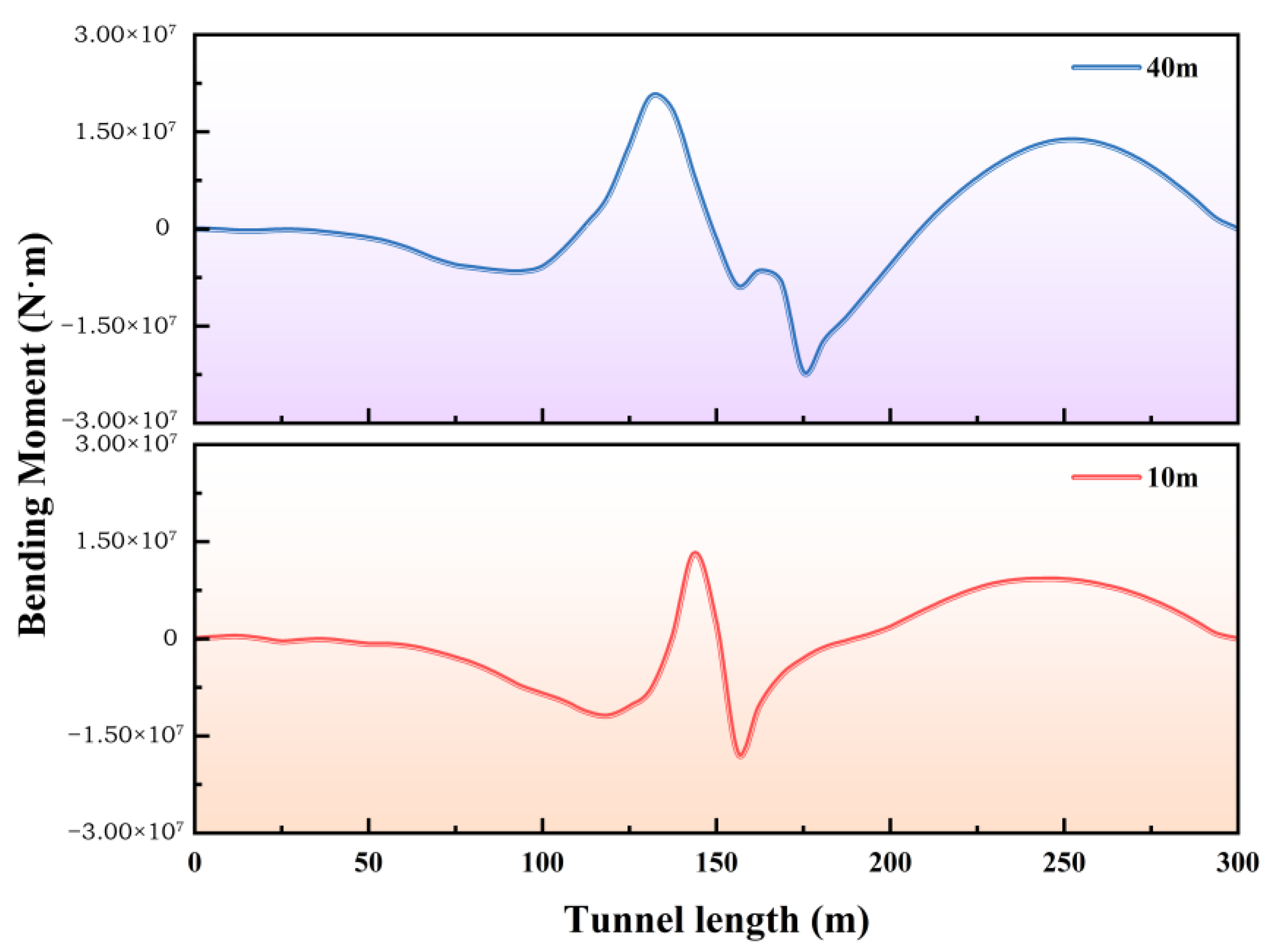
To render the comparison results more prominent, the bending moment data of tunnels traversing faults with widths of 10 m and 40 m are separately chosen in Figure 22. Through analysis, it can be observed that for the tunnel passing through the 10 m wide fracture zone, an extremely steep and large-amplitude peak emerges near the midpoint of the horizontal axis (around 150 m). On either side of this peak, the bending moment value rapidly diminishes to nearly zero. This phenomenon exactly illustrates the characteristic of “concentrated shear”: a substantial shear force is highly concentrated at the central position of the fault, making the tunnel appear as if it is “severed”, and subsequently generating a substantial local bending moment. For the tunnel passing through the 40 m-wide broken zone, near the same midpoint of the horizontal axis, the peak value of the bending moment is significantly reduced (about 20 million magnitude, which is about 1/3 lower than that of the narrow fault). Most importantly, the distribution range of high bending moment values (such as exceeding 5 million) is significantly widened. At this time, it no longer presents as a sharp peak, but forms a wider “platform” or “hilly” distribution pattern on both sides of the fault center. This situation perfectly interprets the characteristic of “distributed bending”: the wider fault zone allows the deformation to be released within a longer tunnel section. The bending moment is no longer concentrated at a certain “point”, but is distributed over a certain “section”, thus effectively avoiding the occurrence of extreme local damage.
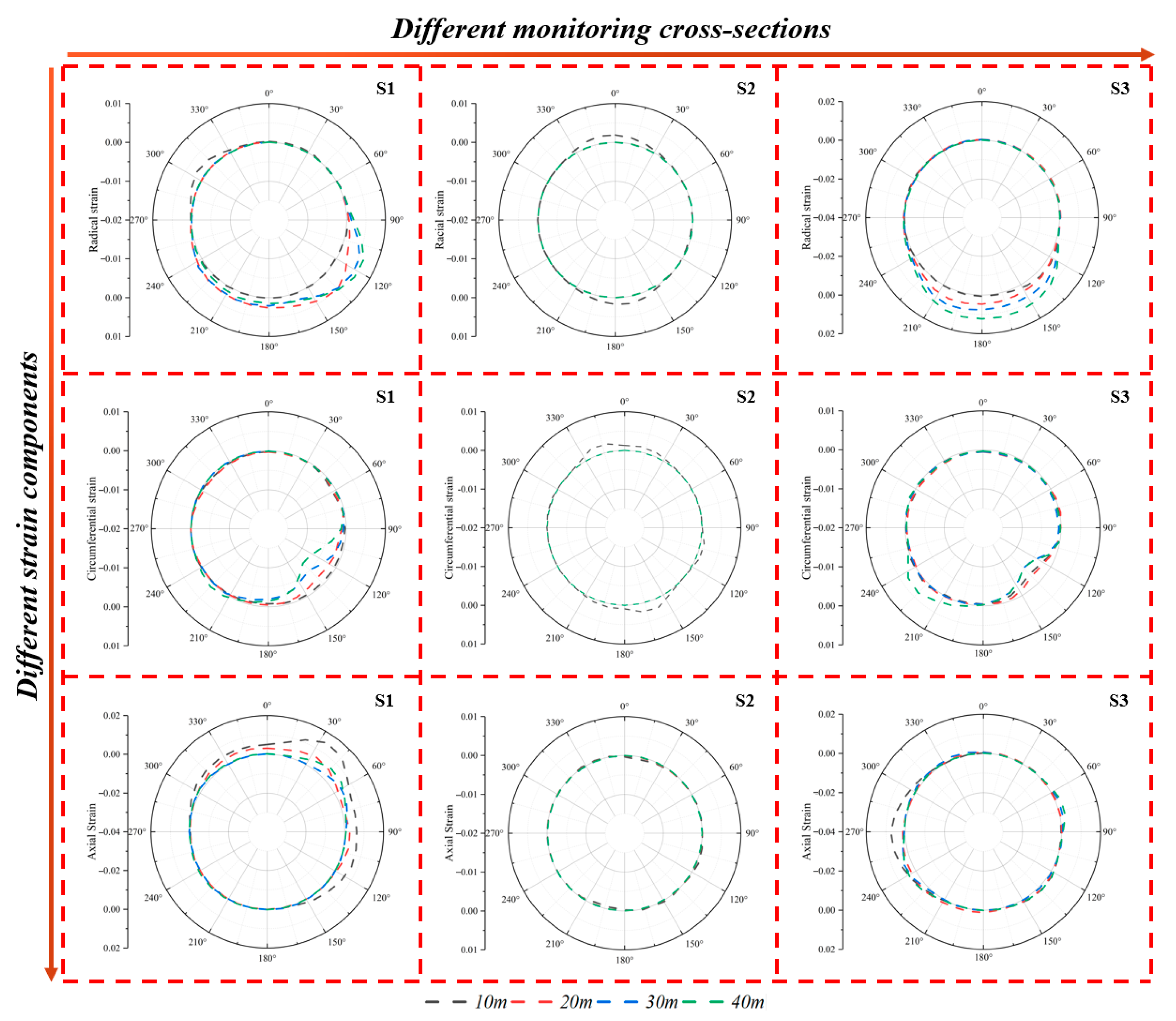
Figure 23 depicts the strain distribution on the monitoring surface under various widths of the fractured zone. At S1, the left arch springing experiences circumferential compression and radial tension. As the width of the fractured zone increases, the axially tensile position gradually moves towards the arch crown. At S2, with the increase in the width of the fractured zone, both circumferential and radial strains indicate that the tensile strains at the arch crown and bottom gradually decrease, while the axial strain shows a slight increase. At S3, the radial tensile strain at the tunnel bottom increases as the width of the fractured zone increases. Regarding the circumferential strain, as the width becomes larger, the left arch springing is slightly under compression, and the axial strain at the right haunch of the arch gradually decreases.

5. Conclusions and Discussions

This study investigates tunnel damage during left-lateral normal fault movement using a three-dimensional finite element model. The model was verified by using the on-site observation data of the Kumamoto earthquake. Based on the engineering data of Xianglushan Tunnel, a parametric analysis was carried out to study the impacts of fault displacement, width, and dip angle on the failure mechanism.
  • Tunnel damage is more severe under strike-slip faulting than under oblique-slip faulting. This is evidenced by a maximum Mises stress of 12.21 MPa under strike-slip motion, which is 30–40% greater than the 11.91 MPa observed under oblique-slip conditions.
  • In the damage resulting from the activity of oblique-slip faults, displacement is the dominant factor. When the fault displacement reaches 80 cm, the failure rate of the vault and the invert within the fault zone is nearly 95%. Hence, when designing cross-fault tunnels, special attention should be paid to measures to resist tunnel faulting.
  • Impact of fault dip angle: With the increase in the dip angle, the failure mode of the tunnel shifts from a tension–compression composite form to a tension–shear composite form. When the dip angle is small, the horizontal component of the fault displacement is significant, and the affected area is extensive. When the dip angle is large, the tension–shear coupling effect becomes more prominent. The deformation becomes more concentrated, resulting in a reduction of approximately 40% in the damaged area of the slip surface, and the propagation of damage towards the center of the fault zone is attenuated. Thus, in practical engineering, it is preferable for the tunnel to cross the fault at a large angle.
  • Influence of the fault zone width: A relatively narrow fault zone (10 m) leads to local concentrated damage, while a relatively wide fault zone (40 m) makes the damage distribution more scattered. When crossing a 40 m wide fault zone, the degree of influence on the center of the fault zone is decreased by 30% compared to the case of a 10 m fault zone, and the damage path is longer. In engineering applications, it is recommended to prioritize the crossing plan of a relatively wide fault zone to realize the transformation from “concentrated shearing” to “distributed bending”, which is in line with the design concept of “using softness to counter hardness”.
This study focuses on a specific oblique-slip mechanism. Future research work should incorporate various forms of fault movement, different rock properties, and seismic dynamics factors to formulate comprehensive design criteria for cross-fault tunnels.

Author Contributions

Conceptualization: C.G.; Methodology: X.H.; Software: X.H.; Validation: C.G., X.H., J.G. and C.X.; Data curation: X.H.; Writing—original draft: X.H.; Writing—review & editing: C.G.; Visualization: X.L.; Supervision: X.L., J.G., C.X. and C.G.; Funding acquisition: C.G. All authors have read and agreed to the published version of the manuscript.

Funding

This work was supported by the Henan Provincial Department of Science and Technology (No.212300410234).

Data Availability Statement

The datasets generated for this study are available on request to the corresponding author.

Conflicts of Interest

The authors declare that they have no known competing financial interests or personal relationships that could have appeared to influence the work reported in this paper.

References

  1. Gong, J.F.; Wang, W.; Wang, F.; Yuan, Y. Statistics of China’s Railway Tunnels by the End of 2023 and Overview of Tunnels of Key New Projects in 2023. Tunn. Constr. 2024, 44, 377–392. [Google Scholar]
  2. Yu, H.T.; Chen, J.T.; Bobet, A.; Yuan, Y. Damage observation and assessment of the Longxi tunnel during the Wenchuan earthquake. Tunn. Undergr. Space Technol. 2016, 54, 102–116. [Google Scholar] [CrossRef]
  3. Yu, H.T.; Yan, X.; Bobet, A.; Yuan, Y.; Xu, G.P.; Su, Q.K. Multi-point shaking table test of a long tunnel subjected to non-uniform seismic loadings. Bull. Earthq. Eng. 2018, 16, 1041–1059. [Google Scholar] [CrossRef]
  4. Yu, H.T.; Yuan, Y.; Liu, X.; Li, Y.W.; Ji, S.W. Damages of the Shaohuoping road tunnel near the epicentre. Struct. Infrastruct. Eng. 2013, 9, 935–951. [Google Scholar] [CrossRef]
  5. Yu, H.T.; Yuan, Y.; Xu, G.P.; Su, Q.K.; Yan, X.; Li, C. Multi-point shaking table test for long tunnels subjected to non-uniform seismic loadings—part II: Application to the HZM immersed tunnel. Soil Dyn. Earthq. Eng. 2018, 108, 187–195. [Google Scholar] [CrossRef]
  6. Zhong, Z.; Wang, Z.; Zhao, M.; Du, X. Structural damage assessment of mountain tunnels in fault fracture zone subjected to multiple strike-slip fault movement. Tunn. Undergr. Space Technol. 2020, 104, 103527. [Google Scholar] [CrossRef]
  7. Wang, W.L.; Wang, T.T.; Su, J.J.; Lin, C.H.; Seng, C.R.; Huang, T.H. Assessment of damage in mountain tunnels due to the Taiwan Chi-Chi Earthquake. Tunn. Undergr. Space Technol. 2001, 16, 133–150. [Google Scholar] [CrossRef]
  8. Hikima, K.; Koketsu, K. Rupture processes of the 2004 Chuetsu (mid-Niigata prefecture) earthquake, Japan: A series of events in a complex fault system. Geophys. Res. Lett. 2005, 32, L18305. [Google Scholar] [CrossRef]
  9. Lai, J.; He, S.; Qiu, J.; Chen, J.; Wang, L.; Wang, K.; Wang, J. Characteristics of seismic disasters and aseismic measures of tunnels in Wenchuan earthquake. Environ. Earth Sci. 2017, 76, 76–94. [Google Scholar] [CrossRef]
  10. Ishibe, T.; Shimazaki, K.; Tsuruoka, H.; Yamanaka, Y.; Satake, K. Correlation between Coulomb stress changes imparted by large historical strike-slip earthquakes and current seismicity in Japan. Earth Planets Space 2011, 63, 301–314. [Google Scholar] [CrossRef]
  11. Blanchard, F.; Laverty, G. Displacements in the Claremont water tunnel at the intersection with the Hayward fault. Bull. Seismol. Soc. Am. 1966, 56, 291–294. [Google Scholar] [CrossRef]
  12. He, C.; Li, L.; Zhang, J.; Geng, P.; Yan, Q.X. Seismic damage mechanism of tunnels through fault zones. Chin. J. Geotech. Eng. 2014, 36, 427–434. [Google Scholar]
  13. Cui, G.Y.; Wang, M.N.; Yu, L.; Lin, G. Study on the characteristics and mechanism of seismic damage for tunnel structures on fault rupture zone in Wenchuan seismic disastrous area. China Civ. Eng. J. 2013, 46, 122–127. (In Chinese) [Google Scholar]
  14. Wang, T.; Geng, P.; Li, P.; Wang, Q.; Wang, L. Deformation and failure of overburden soil subjected to normal fault dislocation and its impact on tunnel. Eng. Fail. Anal. 2022, 142, 106747. [Google Scholar] [CrossRef]
  15. Wang, D.; Zhang, G.Z.; Jiang, L.W. Engineering effect of active fault and geological alignment of Chengdu to Kangding in Sichuan–Tibet Railway. J. Railw. Eng. Soc. 2015, 32, 6–11. [Google Scholar]
  16. Vazouras, P.; Karamanos, S.A.; Dakoulas, P. Finite element analysis of buried steel pipelines under strike-slip fault displacements. Soil Dyn. Earthq. Eng. 2010, 30, 1361–1376. [Google Scholar] [CrossRef]
  17. Cui, Z.; Li, J.H.; Fu, X.W.; Shen, Q.; Zhou, G.X.; Ma, Y.; Wang, T.Q. Evaluating the response of a tunnel subjected to strike-slip fault rupture in conjunction with model test and hybrid discrete–continuous numerical modeling. Rock. Mech. Rock. Eng. 2022, 55, 4743–4764. [Google Scholar]
  18. Yang, H.H.; Wang, M.N.; Luo, X.; Yu, L.; Zhang, X.; Tang, L.Z. Longitudinal and cross-sectional partitioned failure mechanism of tunnels subjected to stick-slip action of strike-slip faults. J. Cent. South Univ. 2024, 31, 250–271. [Google Scholar] [CrossRef]
  19. Du, X.L.; Wang, Z.; Zhao, M.; Zhong, Z.L.; Wang, H.R.; Sheng, Q. Experimental study on articulated design of mountain tunnel crossing strike-slip fault zones. China Civ. Eng. J. 2022, 55, 97–106. [Google Scholar]
  20. Zhang, X.; Wang, M.N.; Li, Z.J.; Yu, L.; Yang, H.H. Mechanical response of tunnels crossing active fault zones under normal or reverse faulting: A refined nonlinear analytical approximate solution. Comput. Geotech. 2024, 167, 106028. [Google Scholar] [CrossRef]
  21. Zhang, X.; Yu, L.; Wang, M.N.; Yang, H.H. Mechanical response and failure characteristics of tunnels subjected to reverse faulting with nonuniform displacement: Theoretical and numerical investigation. Eng. Fail. Anal. 2024, 156, 107809. [Google Scholar] [CrossRef]
  22. Yang, H.H.; Wang, M.N.; Yu, L.; Zhang, X. Analytical and numerical analysis on the mechanical response and damage characteristics of tunnels subjected to multiple normal faulting. Comput. Geotech. 2024, 169, 106254. [Google Scholar] [CrossRef]
  23. Sabagh, M.; Ghalandarzadeh, A. Centrifugal modeling of continuous shallow tunnels at active normal faults intersection. Transp. Geotech. 2020, 22, 100325. [Google Scholar] [CrossRef]
  24. Liu, X.Z.; Li, X.F.; Lin, L.L.; Sang, Y.L. Experimental study on normal fault rupture propagation in loose strata and its impact on mountain tunnels. Tunn. Undergr. Space Technol. 2015, 49, 417–425. [Google Scholar] [CrossRef]
  25. Zhang, J.; Zhao, W.; Cui, Z. Study of mechanical response of tunnels crossing active faults in different burial depths. Buildings 2023, 13, 2723. [Google Scholar] [CrossRef]
  26. Zhang, J.; Cui, Z.; Sheng, Q.; Zhao, W.; Song, L. Experimental study on the effect of flexible joints of a deep-buried tunnel across an active fault under high in-situ stress conditions. Undergr. Space 2024, 19, 189–207. [Google Scholar] [CrossRef]
  27. Zhang, N.; Zhou, H.; Gao, Y.; Zhu, Y.; Lu, J.; Zhao, C.; Cheng, G. Deformation and failure mechanism of deep-buried tunnel under the action of fault dislocation and application of nonlocal model in numerical simulation research. Eng. Fail. Anal. 2025, 174, 109496. [Google Scholar] [CrossRef]
  28. Liu, Z.; Liu, X.; Alsahly, A.; Yuan, Y.; Meschke, G. Mechanics of longitudinal joints in segmental tunnel linings: A semi-analytical approach. Tunn. Undergr. Space Technol. 2025, 163, 106696. [Google Scholar] [CrossRef]
  29. Liu, Z.; Cao, B.T.; Xu, C.; Liu, X.; Yuan, Y.; Meschke, G. Mechanics of longitudinal joints in segmental tunnel linings: Role of connecting bolts. Tunn. Undergr. Space Technol. 2025, 161, 106601. [Google Scholar] [CrossRef]
  30. Liu, X.; Hong, J.; Liu, Z. Investigations on mechanical behavior of longitudinal joints in segmental tunnel linings reinforced with epoxy bonded-bolted steel plates. Tunn. Undergr. Space Technol. 2025, 163, 106724. [Google Scholar] [CrossRef]
  31. Qin, Y.; Zhang, Y.; Liu, Z.; Liu, X. Experimental and analytical investigation of the mechanical behavior of deformed segmental tunnel linings strengthened by stainless steel corrugated plate. Tunn. Undergr. Space Technol. 2025, 157, 106355. [Google Scholar] [CrossRef]
  32. Zhang, D.M.; Guo, L.; Huang, Z.K.; Shen, Y.Y.; Pitilakis, K. Failure mechanism of rock tunnels subjected to combined reversed fault dislocation and subsequent seismic excitation. Comput. Geotech. 2025, 187, 107485. [Google Scholar] [CrossRef]
  33. Wang, T.; Geng, P. Quantitative damage evaluation of tunnel subjected to a subsequent strong seismic after a quasi-static reverse faulting. Eng. Fail. Anal. 2024, 157, 107886. [Google Scholar] [CrossRef]
  34. Xin, C.; Feng, W.; Song, D.; Huang, S.; Liu, X. Seismic damage to non-fault-crossing and fault-crossing tunnels: Comparative study of the 2008 Wenchuan earthquake (Mw 7.9) and the 2022 Menyuan earthquake (Mw 6.7). Eng. Fail. Anal. 2024, 166, 108843. [Google Scholar] [CrossRef]
  35. Wang, H.R.; Zhong, Z.L.; Zhao, M.; Wang, Z.; Zhao, X.; Du, X.L. Model Experimental Study of the Influence of Strike-slip Fault Dislocation on Tunnel. J. Beijing Univ. Technol. 2021, 47, 691–701. [Google Scholar]
  36. Shen, Y.; Gao, B.; Yang, X.; Tao, S. Seismic damage mechanism and dynamic deformation characteristic analysis of mountain tunnel after Wenchuan earthquake. Eng. Geol. 2014, 180, 85–98. [Google Scholar] [CrossRef]
  37. Wang, Z.; Zhong, Z.L.; Zhao, M.; Du, X.-L. Research on simulation of normal faults and their influence on mountain tunnels. Chin. J. Geotech. Eng. 2020, 42, 1876–1884. [Google Scholar]
  38. Halabian, A.M.; Hokmabadi, T. A new hybrid model for rigorous analysis of buried pipelines under general faulting accounting for material and geometrical non-linearities with focusing on corrugated HDPE pipelines. Soil Dyn. Earthq. Eng. 2018, 115, 1–17. [Google Scholar] [CrossRef]
  39. British Standards Institution. Code of Practice for Temporary Works Procedures and the Permissible Stress Design of Falsework: BS5975; British Standards Institution: London, UK, 2008. [Google Scholar]
  40. Zhao, K.; Chen, W.Z.; Zhao, W.S.; Yang, D.S.; Song, W.P. Study on parameters of articulated design of tunnel lining under reverse fault dislocation. Chin. J. Rock Mech. Eng. 2018, 37, 3411–3421. (In Chinese) [Google Scholar]
  41. Byerlee, J. Friction of rocks. Pure Appl. Geophys. 1978, 116, 615–626. [Google Scholar] [CrossRef]
  42. Panet, M.; Guenot, A. Analysis of convergence behind the face of a tunnel. In Proceedings of the 3rd International Symposium, Brighton, UK, 7–11 June 1982. [Google Scholar]
  43. Andreotti, G.; Lai, C.G. Use of fragility curves to assess the seismic vulnerability in the risk analysis of mountain tunnels. Tunn. Undergr. Space Technol. 2019, 91, 103008. [Google Scholar] [CrossRef]
  44. Ministry of Transport of the People’s Republic of China (MTPRC). Guidelines for Design of Highway Tunnel (JTG/T D70); China Communications Press: Beijing, China, 2010. [Google Scholar]
  45. Billen, M.; Cowgill, E.; Buer, E. Determination of fault friction from reactivation of abyssal-hill faults in subduction zones. Geology 2007, 35, 819–822. [Google Scholar] [CrossRef]
  46. Zhang, X.P.; Jiang, Y.J.; Sugimoto, S. Seismic damage assessment of mountain tunnel: A case study on the Tawarayama tunnel due to the 2016 Kumamoto Earthquake. Tunn. Undergr. Space Technol. 2018, 71, 138–148. [Google Scholar] [CrossRef]
  47. Wei, Y.M.; Wei, X.H.; Li, D.W.; Chen, Y.; Shen, X.; Sun, C. Remote sensing image characteristics and activity analysis of the Heqing-Eryuan fault zone in northwest Yunnan. Quat. Sci. 2017, 37, 234–249. (In Chinese) [Google Scholar]
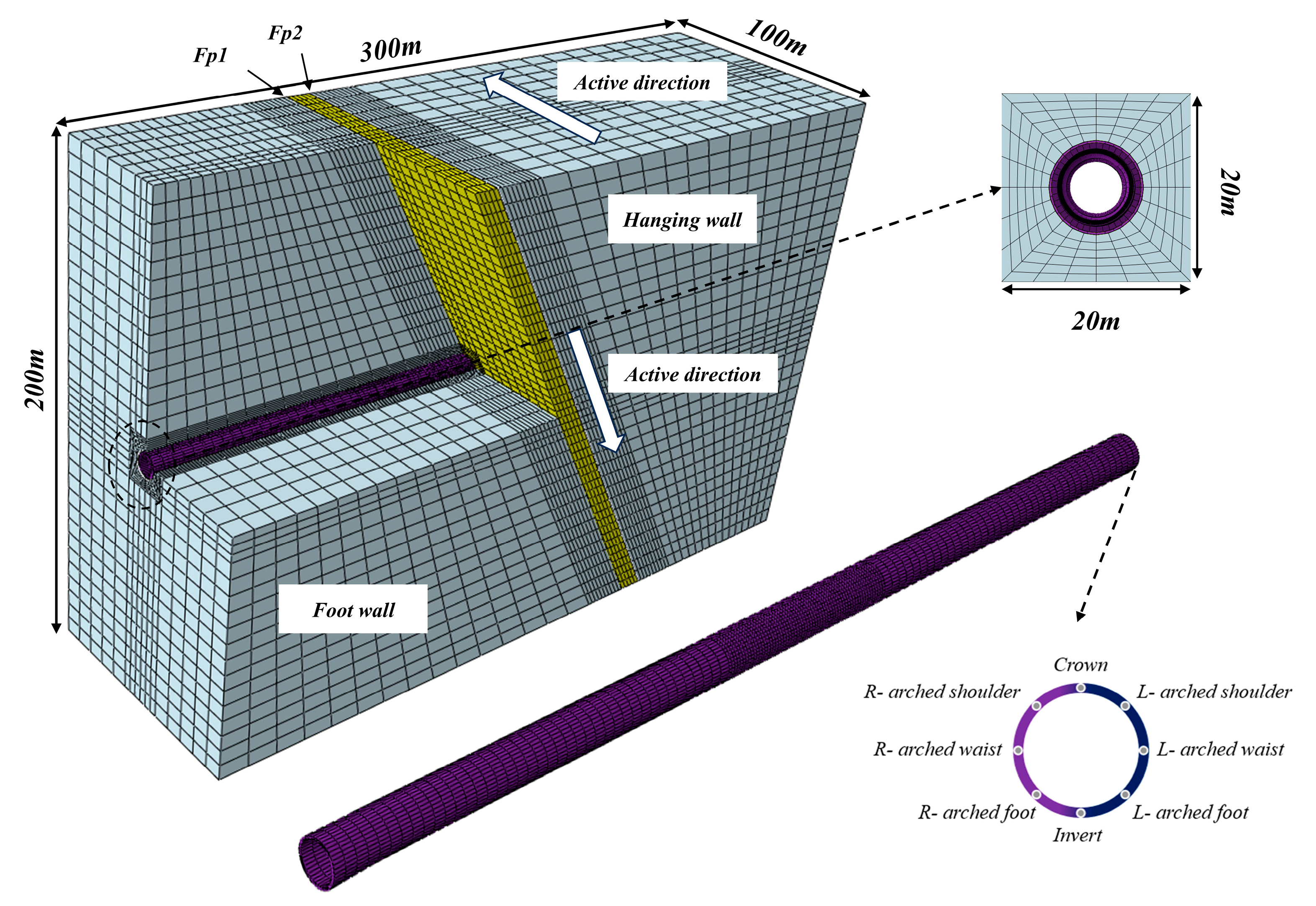
Figure 1. Numerical analysis model in three dimensions for the surrounding rock and the tunnel.
Infrastructures 10 00314 g001
Figure 2. The damage plasticity curve of C30 concrete: (a) Compression damage curve; (b) Tensile damage curve.
Infrastructures 10 00314 g002
Figure 3. Numerical simulation process: (a) In situ stress balance; (b) The simulation process of tunnel excavation; (c) Forced displacement of the movable disk. The yellow arrows indicate the direction and application points of the applied stress/displacement.
Infrastructures 10 00314 g003
Figure 4. Validation of FE simulation results against the actual tunnel damage observed in the Kumamoto Earthquake: (a) The results of the simulation; (b) The tunnels damaged in the Kumamoto earthquake [46].
Infrastructures 10 00314 g004
Figure 5. Displacement nephogram of the tunnel affected by the displacement of the oblique-slip fault: (a) Vertical deformation nephogram; (b) Horizontal deformation nephogram.
Infrastructures 10 00314 g005
Figure 6. Stress states of the tunnel during oblique-slip fault movement: (a) Axial stress; (b) Maximum principal stress; (c) Shearing stress in the vertical direction; (d) Shearing stress in the horizontal direction.
Infrastructures 10 00314 g006
Figure 7. Tunnel Stress under different fault movements.
Infrastructures 10 00314 g007
Figure 8. Tunnel tensile damage under different fault movements.
Infrastructures 10 00314 g008
Figure 9. Tunnel tensile damage across various fault movements.
Infrastructures 10 00314 g009
Figure 10. Case diagram of oblique sliding and misalignment: (a) Vertical dislocation morphology; (b) Horizontal dislocation morphology.
Infrastructures 10 00314 g010
Figure 11. The deformation rate of the tunnel’s oblique diameter follows the fault movement at different fault displacements.
Infrastructures 10 00314 g011
Figure 12. Tunnel tensile damage caused by different fault displacements.
Infrastructures 10 00314 g012
Figure 13. Tunnel compression damage due to different fault displacements.
Infrastructures 10 00314 g013
Figure 14. Strain components of each monitoring face in tunnels with different fault displacements.
Infrastructures 10 00314 g014
Figure 15. The deformation rate of the tunnel’s oblique diameter follows the fault movement at different dip angles.
Infrastructures 10 00314 g015
Figure 16. Compressive damage in tunnels with different fault inclinations.
Infrastructures 10 00314 g016
Figure 17. Tensile damage in tunnels with different fault inclinations.
Infrastructures 10 00314 g017
Figure 18. Strain components of each monitoring face in tunnels with different fault inclinations.
Infrastructures 10 00314 g018
Figure 19. The deformation rate of the tunnel’s oblique diameter follows the fault movement at different widths of the fault fracture zone.
Infrastructures 10 00314 g019
Figure 20. Tunnel compressive damage under different widths of the fault fracture zone.
Infrastructures 10 00314 g020
Figure 21. Tunnel tensile damage under different widths of the fault fracture zone.
Infrastructures 10 00314 g021
Figure 22. The comparison of the bending moments of the tunnel passing through the 10 cm and 40 cm fault fracture zone.
Infrastructures 10 00314 g022
Figure 23. Strain components of each monitoring face in tunnels with different widths of fault fracture zone.
Infrastructures 10 00314 g023
Table 1. Geomechanical parameters of the Heqing–Eryuan Fault [37].
TypeDensity ρ/103 kg⋅m−3Elastic Modulus E/Gpa Poisson’s Ratio
ν
Internal Friction Angle
φ/(°)
Cohesion Force c/Mpa
Intact rock2.97.50.28451.1
Fault fracture zone2.11.50.33290.15
Table 2. Mechanical parameters of the C30 concrete.
TypeDensity ρ/103 kg⋅m−3 Elastic Modulus E/Gpa Poisson’s Ratio
ν
Dilation Angle φ/(°) Compressive Yield Stress fc/Mpa Tensile Yield Stress
ft/Mpa
Concrete2.5 × 103300.236.3120.12.01
Table 3. Numerical Simulation Case analysis.
CaseHorizontal Displacement Distance (m)Fault Dip Angle (°)Fault Width (m)Tendency Dislocation Distance (m)
10.250/60/70/80100.04
20.26010/20/30/400.04
30.2/0.4/0.6/0.860100.04/0.08/0.12/0.16
Disclaimer/Publisher’s Note: The statements, opinions and data contained in all publications are solely those of the individual author(s) and contributor(s) and not of MDPI and/or the editor(s). MDPI and/or the editor(s) disclaim responsibility for any injury to people or property resulting from any ideas, methods, instructions or products referred to in the content.