1. Introduction
In recent years, structural steel has gained popularity as a sustainable construction material due to its ability to be fully recycled without losing its chemical or mechanical properties. It is one of the most widely used building materials, with over 1.6 billion tons produced annually [
1]. However, its production also exhibits a significant carbon footprint, accounting for 7% (2.6 billion tons) of global emissions in 2023 alone [
2]. Additionally, the construction industry generates a significant amount of waste each year, approximately 120 million tons, much of which is either not recycled or downgraded in quality compared to its original state [
3].
The concept of reusing structural steel emerged in the past decade and has gained increasing attention in response to growing concerns about sustainability in construction. This process involves collecting steel components from structures that are about to be decommissioned and integrating them into new projects, provided they meet the required strength and performance criteria [
4]. Reusing structural steel offers several benefits to the industry, including a reduced demand for new steel production, the conservation of resources, and a minimization of construction waste sent to landfills for scrapping [
5,
6,
7].
One of the key challenges in this process is determining the material properties of recovered steel to assess whether it is suitable for reuse. To address this, protocols and regulations have been developed in both Europe and the United States. The Steel Construction Institute (SCI) is a globally recognized source of engineering expertise in steel construction, with extensive research and practical contributions to the field. In recent years, SCI has focused on steel reuse research to align with the latest Eurocode regulations (EN 1090) [
8]. The institute has recently completed two major research projects that outline a protocol for collecting, evaluating, and testing recovered steel to ensure its safe and reliable use in new projects. Another major contributor to steel reuse research is the Alliance for Sustainable Building Products (ASBP), a nonprofit organization that promotes sustainable construction practices [
9]. In 2023, ASBP hosted the “DISRUPT EVENT”, which highlighted the advantages of steel reuse over conventional recycling and showcased projects built using recovered steel. Quite recently, the Ministry of Regional Development and Housing of Baden-Württemberg, Germany, published a guideline for the reuse of bearing structural components [
10], where a structured approach to assess and reuse structural steel and timber elements, covering all key stages from inventory analysis and selective dismantling to mechanical testing and structural requalification, is presented. Crucially, it provides specific technical procedures for verifying material properties and determining structural safety in compliance with German building regulations.
1.1. Benefits of Reuse
At the end of its service life, steel is sent for recycling, where it is shredded and placed into specialized furnaces to be melted. The same high temperatures as during raw steel production are being applied, leading again to significant energy consumption. The molten steel is then poured into molds and reformed into new steel, retaining the properties of the original material. A recent study [
11] indicated that, as of 2023, steel recycling using Electric Arc Furnaces—allowing up to 100% recycled material, even when powered by solar energy—still results in 0.3–0.9 t CO
2 per ton of steel. Although these values are considerably lower than the emissions associated with producing new steel, it is highly expected that reusing recovered steel can further reduce the environmental impact, even compared to conventional recycling. This contributes substantially to a more sustainable and eco-friendly construction industry.
Additionally, it is essential to support informed decision-making with realistic cost data during the conceptual design phase, before refinement, and throughout the detailed design stages [
9]. This is a challenging process, as the cost of structural steel fluctuates with the economic cycle and is also heavily influenced by project-specific factors, such as scheduling, accessibility, spans, and structural system. Considering, for example, the construction of a multi-story steel building, the erection process involves multiple stages, each with varying costs, depending on the project type and the agreement made with the client. However, in general, the costs of a typical steel structure across its various completion steps can be estimated and/or allocated. A study by the Australian Steel Institute (ASI) has shown that the cost of a multi-story steel building frame is distributed among many activities such as fabrication, transportation, fire design, and more [
12]. According to the same study, the cost of the steel frame alone accounts for 15–20% of the total construction cost, which is evidently significant.
1.2. Collection and Classification of Recovered Steel
The process of gathering information about steel intended for reuse begins before the demolition of an existing structure. At this stage, the engineer must document key details about the existing structure, including its year of completion. As a general rule, only steel produced after 1970 is considered for reuse, since older steel may not comply with Eurocode regulations [
12,
13]. Additionally, understanding the function of the previous structure is crucial, as it helps predict specific characteristics of certain components and allows for their proper classification.
Following the disassembly of the existing structure and the classification of its components, a thorough inspection is conducted to identify damage caused by fire or corrosion. During the supervisory inspection, components with significant deformations are also rejected, as all recovered steel elements must comply with the latest Eurocode specifications regarding permissible geometric imperfections or existing deformations. If a component exhibits severe deformation and has already undergone yielding, it is deemed unsuitable for reuse. However, if the deformations are minor, the component may still be reused after undergoing an appropriate straightening process [
14].
After this preliminary inspection, the steel members evaluated as suitable for reuse are transported to a specialized facility for a series of experimental tests to certify their structural integrity. The first step involves precise 3D measurements of their dimensions to determine the distances between key points and create a digital map of lengths, distances, angles, and eventual bolt holes. This process requires highly accurate surveying instruments capable of detecting even small imperfections, especially for projects requiring high precision, such as those dealing with structural elements significantly prone to initial defects (for example those classified as Category 4 members under EC3). Once all the dimensions of the recovered components have been recorded, the next step involves conducting both non-destructive and destructive tests to assess the necessary material properties.
1.3. Mechanical Properties and Weldability
The key properties of reclaimed steel that typically need to be calculated include yield strength, elongation, toughness, and, if welding is required, its Carbon Equivalent Value (CEV) [
15]. In order to properly assess reclaimed steel work, after collecting and grouping it, non-destructive and destructive tests will be performed exemplarily on a representative sample from the group, roughly three or four specimens, so that the whole group can be classified. Non-destructive tests, such as X-ray scanning, ultrasound, and magnetic field testing, aim at ensuring that the reclaimed steel does not contain inner cracks at key joints like the welding of the flange and web in built-up members. Destructive testing can be quite time-consuming, making the entire concept of steel reuse less appealing. A reliable way to estimate ultimate and yield strengths is through the steel hardness [
16], which is defined as the resistance of a metallic material to local plastic deformation and depends on the chemical properties of the steel. Hardness is measured at specific locations under examination, with the most important being the weld centerline, the face or weld deposit areas, and the heat-affected zone.
In addition to the non-destructive testing of each member, a representative number of destructive tests are required, taken from any member of the group, to confirm the initial assessment. A single test does not hold statistical significance and is therefore described as “non-statistical”. A non-statistical destructive test is recommended for steel used in Category 1 or 2 execution classes [
8]. If the recovered steel is to be used in Category 3 structures, a higher level of reliability is required. The mechanical properties of steel members should be determined by increasing the number of destructive tests and completing the evaluation in accordance with EN 1990. At least three destructive tests are required, taken from members of a group. Increasing the number of tests improves the accuracy and reliability of the calculated values and generally results in higher values [
17,
18,
19].
1.4. Objective of the Present Study
Wind turbines, which have become a widespread renewable energy harvesting infrastructure world-wide, are designed for a typical service life of 20–25 years, after which decommissioning is usually required due to fatigue considerations [
20]. As the first generation of onshore wind farms in Europe and elsewhere reaches this threshold, sustainable solutions for end-of-life management are urgently needed. Recent research has primarily focused on the reuse of blades, which are difficult to recycle due to their composite materials [
21,
22]. In contrast, little attention has been given to the towers, despite the fact that they are the heaviest components of the turbine system and consist almost entirely of high-grade structural steel. At present, the common practice is to scrap and recycle the towers, which still involves high energy consumption comparable to primary steel production [
23].
From both environmental and economic perspectives, direct reuse of tower sections may be more beneficial than recycling, as it extends the life cycle of the material, while reducing carbon emissions and fabrication costs [
24]. A single tubular steel tower may weigh tens to hundreds of tons, offering significant potential for circular construction if repurposed for new structural applications. To the authors’ knowledge, there are no systematic investigations on reusing decommissioned wind turbine towers, despite the large number of first-generation towers already reaching the end of their design life. The present study aims to pave the path towards a new subfield in steel reuse, dealing with towers of decommissioned wind turbines, by demonstrating the feasibility of reusing these structural components in alternative infrastructure applications.
Considering that, during their operations as part of the tower, the cylindrical of conical shells of such tubular structures have experienced a high number of stress cycles and may have accumulated fatigue damage, it is preferable to target applications in which these parts will not be subjected to further significant stress cycles. For that reason, reuse in a pedestrian bridge and a water tank are selected, both being structural types for which fatigue verification is not required by pertinent codes. Moreover, it is assumed that the reused components will be subjected to the process described in
Section 1.2 and
Section 1.3 and will be free of defects and deemed suitable for reuse.
Objective of this paper is not to present final design of the two case studies, but rather to employ them in order to demonstrate the concept of reusing tubular tower segments in other applications, and to prove their structural feasibility for such purpose by means of preliminary static analyses. Logistical aspects are also discussed towards promoting the proposed concept and encouraging further research towards actual implementation.
2. Materials and Methods
2.1. Tubular Wind Turbine Towers
Wind turbines are structures that harness wind energy to generate electricity by converting air flow into mechanical power. Widely regarded as one of the most prominent renewable energy sources, they have become increasingly common across the globe, both onshore and offshore, since their introduction in the 1980s. A wind turbine consists of various functional parts that are interconnected in such a way as to ensure the optimal conversion of wind energy into electrical energy [
25]. The wind turbine includes the tower supporting the nacelle, which houses a large number of mechanical components. Attached to the nacelle is the rotor, to which the blades are connected.
Most wind turbine towers are tubular. They typically consist of two or more sections, each with a maximum length of approximately 30 m to enable transportability, bolted together on site [
26]. These sections are manufactured in a factory from cold-rolled steel plates of varying thickness, measuring 2 to 3 m in width, which are shaped into the desired cylindrical or conical form through roller bending. The edges are milled to allow for full penetration welding, creating a sealed shell. These shells are then welded together, resulting in 15 to 30 m long sections. Adjacent sections are bolted together during erection via ring flanges and prestressed bolts. The maximum diameter for steel towers is around 4.5 m, as this is the largest width/height that can be transported by road.
The two most significant loads acting on the tower are gravity loads, including the self-weight of the tower and the weight of the nacelle, and wind thrust. The combination of these actions results in axial forces, shear forces, and bending moments along the height, which must be resisted by the tower section. A key structural check involves verifying the developed stresses at the base, at the connection points, and at all cross-sections over the tower height. Due to the structural system, the primary displacement is the horizontal movement of the top of the tower, which must remain within a reasonable range for the serviceability limit state. Regulations define a maximum displacement limit of 1% of the tower height to ensure proper operation. Other crucial factors in tower design are buckling and fatigue verifications. Wind pressure is inherently a dynamic load, and variations in its magnitude and direction may lead to multi-cycle fatigue failure of the tower’s welded and bolted connections. Fatigue may be crucial in terms of reusing the tower sections in new applications [
27], for that reason applications that are not fatigue-prone are preferable.
Wind turbines typically have a lifespan of 20 to 25 years, and with modifications, the expected life can be extended by approximately 5 years [
22,
23]. Once this period is over and the operational phase ends, the wind park operator is required to decommission the turbine and remove it from the park. The current practice regarding the tower is to recycle it at a specialized industrial waste processing unit (scrapping). Wind turbines are made from recyclable materials by 96%. The mechanical equipment, electrical components, and tower are made of structural steel, aluminum, copper, and other materials that can be recycled.
However, the blades are made of composite materials, such as fiberglass-reinforced polyester or carbon fibers, which make them extremely durable over time and nearly impossible to recycle [
22]. When the life cycle of the wind turbine comes to an end, the components are disassembled, the blades are cut into 2 or 3 pieces depending on their size and are being stacked in landfills. As wind turbines approach the end of their life cycle, engineers have devised ways to repurpose the blades. For instance, a children’s playground in the Netherlands and a bicycle shelter in Denmark have been erected using decommissioned blades [
28,
29,
30].
Regarding the tower on the other hand, the most common practice is to scrap it away, at best. No reuse applications of tubular steel wind turbine towers have been reported in the literature. In compliance with the aforementioned global need for steel reuse in the construction industry, the present study aims at encouraging reuse rather than recycling of towers. Towards that goal, the feasibility of two reuse applications for decommissioned wind turbine towers is demonstrated, based on the geometric dimensions of a real tower from an existing wind turbine that is about to reach the end of its nominal life.
2.2. Research Methodology
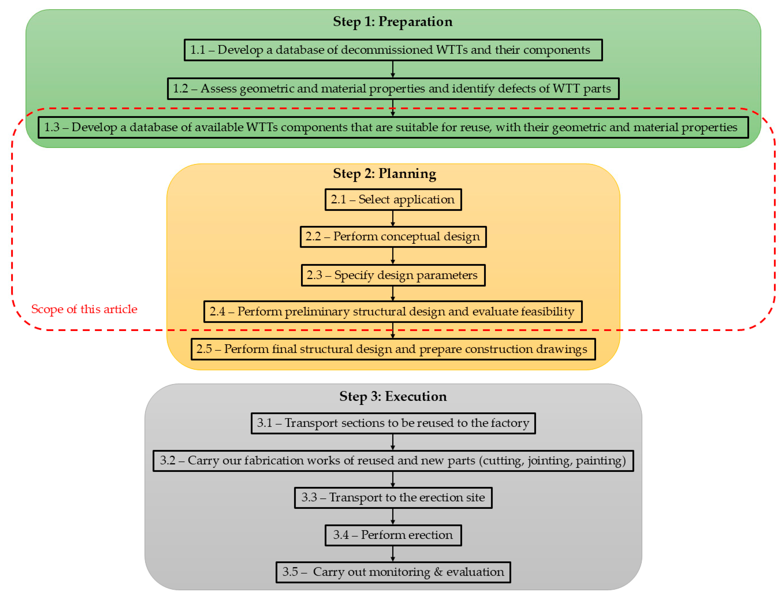
The flow chart shown in
Figure 1 illustrates the proposed reuse methodology, comprising preparation, planning and execution works. The tasks identified by the box with red dotted lines are addressed in the present research. It is assumed that a decommissioned tower is available, described in
Section 2.3, for which geometric and material data are known. It is further assumed that, prior to reuse, the selected tower sections will be subjected to the necessary geometrical and material checks described in
Section 1.2 and
Section 1.3 and will be found free of defects and deemed suitable for reuse.
Sections of the tower are selected for reuse (step 1.3) so that they exhibit a geometric fit to a desirable application (step 2.1). After considering several potential reuse applications, two representative case studies were selected to evaluate the feasibility of incorporating parts of a decommissioned wind turbine tower into new structural systems. The specific applications, a pedestrian bridge and a water storage tank, were conceived based on several key considerations:
Geometric compatibility with the desired structural performance: Wind turbine towers possess sufficient length to meet the typical span requirements of pedestrian bridges. Their curved steel shells also exhibit considerable bending and torsional stiffness, even when cut into segments. Similarly, their cylindrical or conical geometry closely resembles that of water tanks, designed for withstanding internal pressure.
Minimization of material waste: For the pedestrian bridge concept, the tower is longitudinally cut in half, and both halves can be utilized for erecting twin bridges, thereby enhancing modularity and reducing design and material costs. In the water tank scenario, the tower’s existing geometry is largely retained, eliminating material waste entirely.
Structural adequacy based on engineering judgment: Wind turbine towers are built to withstand significant loads, including extreme wind and rotor forces. In contrast, pedestrian bridges are subject primarily to lower-intensity pedestrian and wind loads, while water tanks experience mainly hydrostatic pressure. Therefore, the towers are expected to have sufficient residual strength for both proposed reuse cases.
Reduction in fatigue exposure: Given that these towers have undergone millions of stress cycles during their operational life, future use should ideally involve minimal cyclic loading. Both proposed applications, pedestrian bridges and water tanks, are typically not governed by fatigue design criteria under current standards, making them ideal candidates for reuse.
Minimization of cutting and joining operations: Although fabrication processes like cutting and welding emit less CO2 than producing new steel components, they still contribute to the overall environmental footprint. These reuse scenarios were selected to minimize such interventions. For the bridge, a single longitudinal cut is sufficient, while for the water tank, no major cutting is needed. In both cases, joining requirements (e.g., welding, bolting) are similar or less to those of new structures of the same functionality.
Societal and environmental benefits: The proposed applications contribute to public infrastructure and promote sustainable practices. A pedestrian bridge provides safe, low-carbon mobility solutions, while a water tank serves community needs such as irrigation or emergency water supply. Both examples raise public awareness of circular construction and demonstrate the viability of large-scale steel reuse.
Using the selected wind turbine tower sections, conceptual designs of both structures were developed (step 2.2). In each case, it was necessary to supplement the reused tower section with other, either newly fabricated or repurposed from other sources, steel or concrete components, to form a realistic and complete structural system; however, the repurposed tower segment remained the primary load-bearing element. Presenting the conceptual design combining tower sections and other components is the first step of the presented research process.
The erection site, for the purposes of this article, was set to be in a region of northern Greece, and design parameters were determined accordingly (step 2.3). Wind velocities and air temperature were considered by wind and temperature maps for the assumed erection location to be 33 m/s (basic wind velocity) and 20 °C (air temperature differential), respectively. The seismic actions were obtained using the elastic spectrum of Eurocode 8 for an earthquake with a return period of 475 years, considering a seismic ground acceleration of 0.16 g.
Subsequently, numerical models were prepared for each case study, and structural analyses were performed for loads and load combinations in accordance with the relevant Eurocodes. Structural verifications were also performed according to the Eurocodes, verifying structural adequacy at preliminary design level, thus confirming the feasibility of the proposed concept (step 2.4). To account for potential material degradation due to years of service, a conservatively reduced yield strength was adopted, effectively introducing an additional safety margin in the design verifications, as further detailed in
Section 2.3. To augment feasibility evaluation, considerable attention was also given to the logistical aspects. Final structural design (step 2.5) is beyond the scope of this article, as well as the tasks related to execution.
2.3. Examined Tower
For the case studies examined in this paper, existing wind turbine towers from the pilot wind farm of the Greek Center for Renewable Energy Sources (CRES) in the area of Keratea, Attica, Greece, have been reviewed. In 1999, CRES established in that area a demonstration wind farm and an Energy Education Park, both of which remain operational today. The wind farm is connected to the Public Power Corporation’s (DEI) distribution network, supplying the generated electricity. At full capacity, the farm has an installed power of approximately 3 MW and produces annually 7.6 GWh of electricity [
31]. The goal of the demonstration wind farm was to install five wind turbines, collectively providing 3.01 MW, for the evaluation and demonstration of available wind turbine technologies.
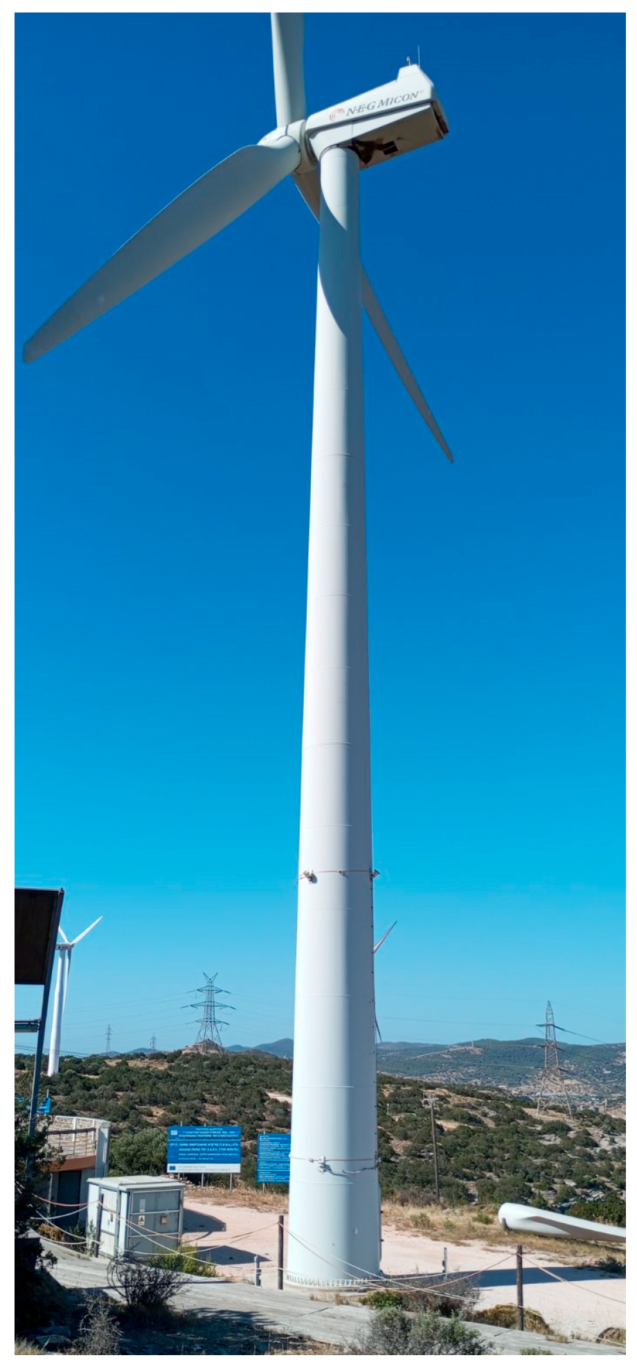
Over time, many turbines at the park have reached or even exceeded their expected lifespan and are set to be decommissioned soon. As part of the present research, a site visit was conducted to the wind farm and CRES headquarters to gather detailed information on the existing wind turbines, their maintenance, and technical descriptions of their towers. Among the many turbines at the demonstration site, a wind turbine of type NEGMICON 750 kW, shown in
Figure 2, was selected for this study, based on its manufacturing date [
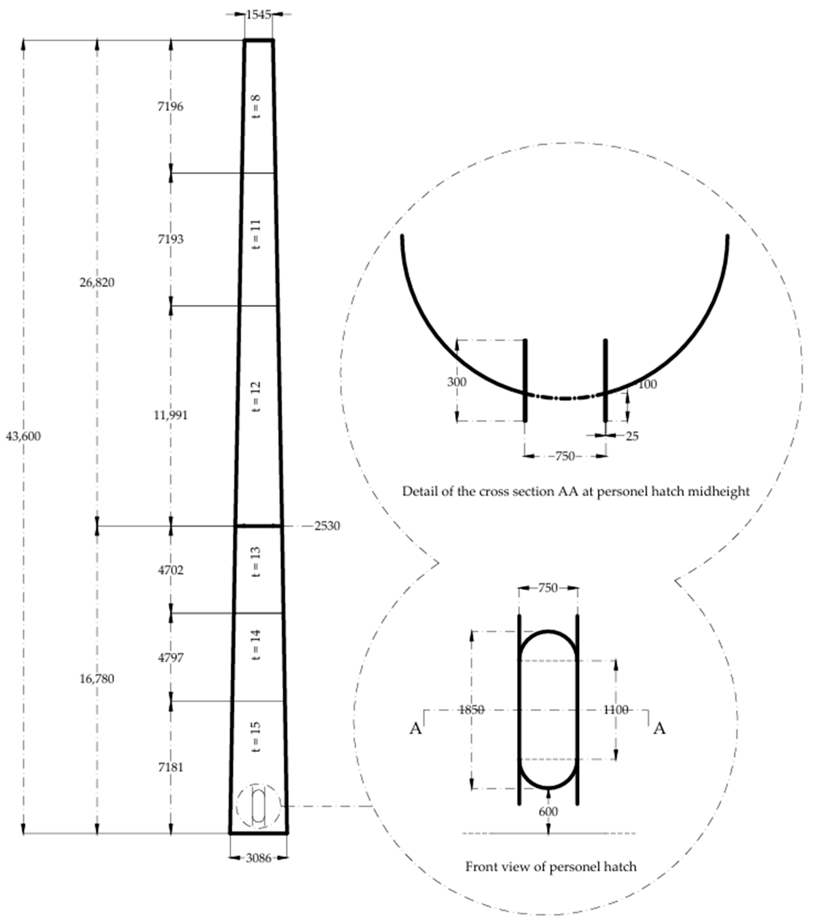
32]. The original technical drawing of the tower is available, from which full geometric data have been obtained. A simplified sketch, drawn in AutoCAD software version 1.2 of 2025 [
33], containing only the essential geometric information is illustrated in
Figure 3.
The tower has a height of approximately 46 m and consists of two conical sections. The base diameter is 3055 mm, the diameter at the bolted connection is 2545 mm, narrowing down at the top to 1445 mm. The first section is 16.7 m in height, with a thickness ranging from 15 mm to 13 mm. The second section is approximately 26 m tall, with a thickness ranging from 12 mm to 8 mm. All steel members have a nominal yield strength of 355 MPa.
For the purposes of the present study and to ensure the feasibility of reuse, an overconservative estimate of the yield strength at 260 MPa has been adopted instead of the original nominal value of 355 MPa. This 25% reduction in yield strength is far larger than reported changes in yield strength for various types of steels due to fatigue loading [
34], aging processes [
35], plastic deformation associated with aging [
35], etc., and can be therefore safely assumed to be an overconservative estimate for the scope of the present study. In a real-life application, the actual yield strength would be determined from hardness and tension tests.
The proposed reuse applications should fully leverage the tower’s geometry and structural capabilities. It is expected that the new structures would have sufficient ductility and seismic capacity and could therefore be deployed in seismic areas, but on the contrary the bearing of fatigue-inducing loads should be avoided, as their welded connections probably are approaching or have already exceeded their nominal fatigue life. Accordingly, the following case studies that explore potential reuse of the tower have been further analyzed.
2.4. Case Study 1: Pedestrian Bridge
Bridges present numerous complexities in terms of analysis, dimensioning, and erection, making specialized knowledge essential for those working in this field. Pedestrian bridges are often characterized by an elegant design, requiring imagination and architectural considerations. In the hypothetical scenario of using part of the decommissioned tower as the main component of a small pedestrian bridge, an investigation has been conducted at preliminary design level. The second section of the tower will be cut longitudinally, starting from its base and extending to a length of 15 m. Then it will be cut transversely to create two semi-frustoconical shapes. The diameter at the base comprises the aforementioned 2545 mm, while the diameter at the 15 m mark was calculated to be 2042 mm, taking into account the constant change in inclination. This section exhibits a transition in wall thickness at the middle, from 13 mm to 12 mm.
Graphic illustrations of the proposed structure were prepared on Rhinoceros 6 software [
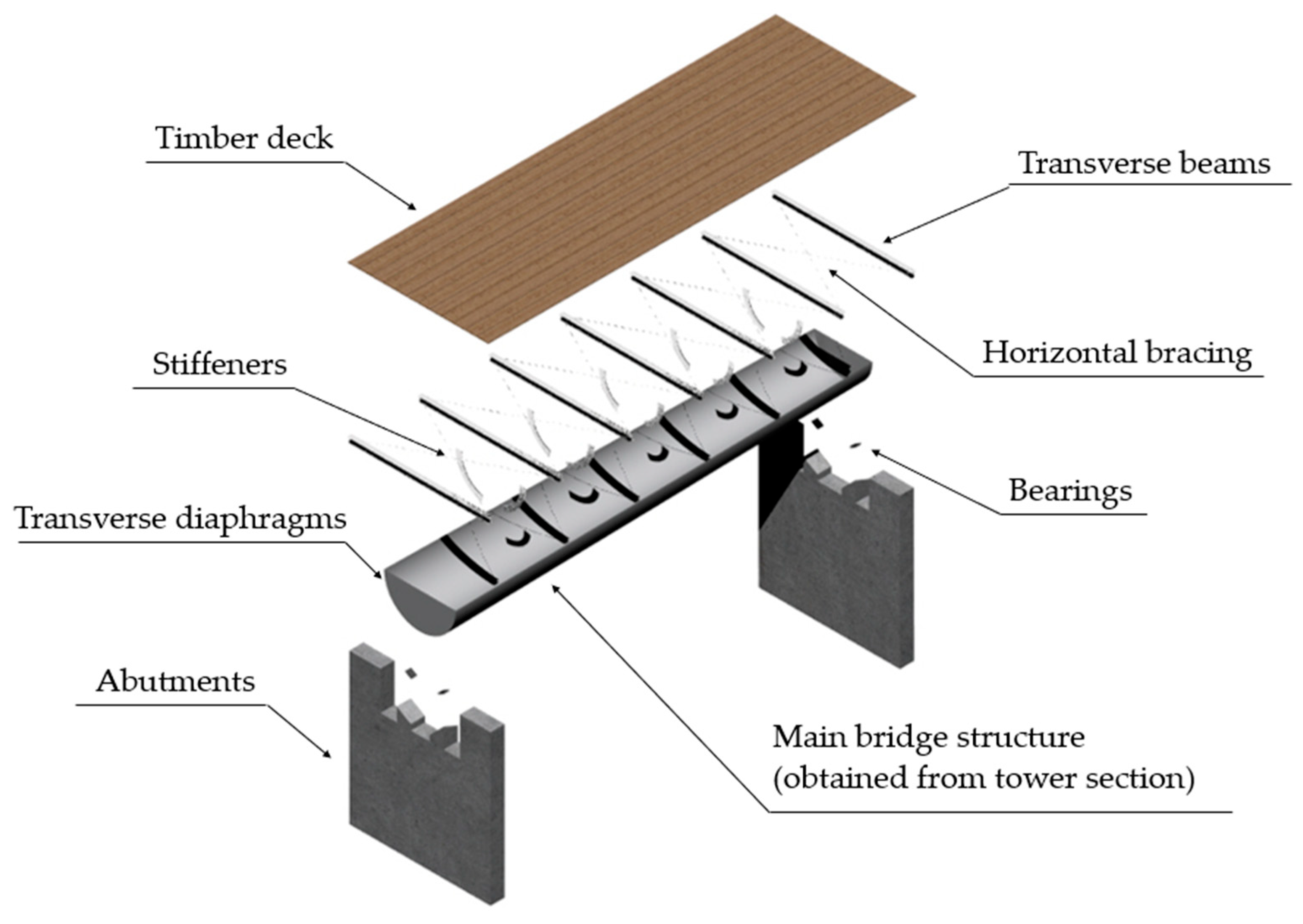
36]. A 3D exploded view of the conceptual design is provided in
Figure 4 to provide a general overview of the main structural components, while more detailed views with the main dimensions are given in
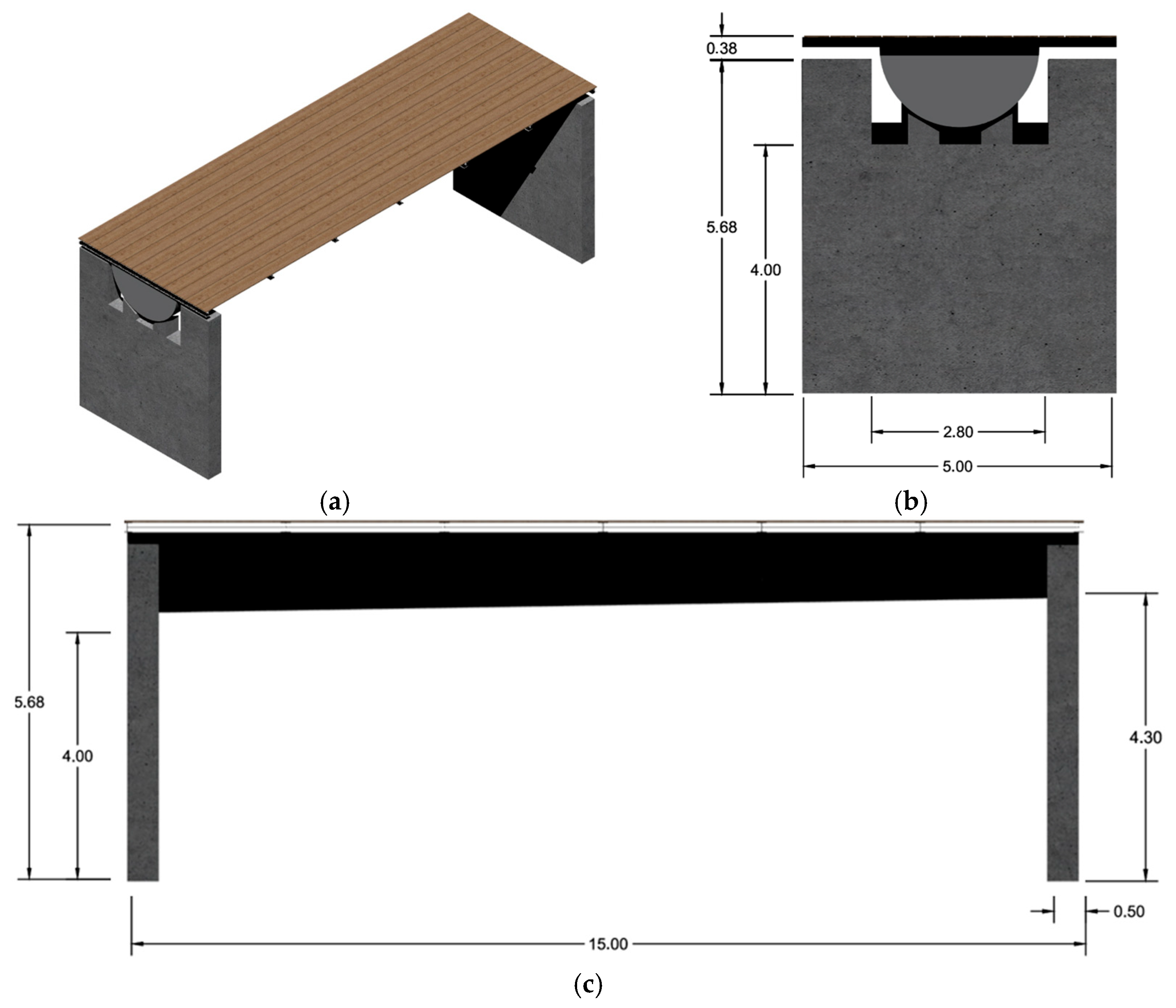
Figure 5. The aforementioned part of the bottom tower section constitutes the main bridge structure, acting in a simply supported manner between two reinforced concrete abutments. The bridge deck consists of steel transverse beams comprising HEA160 sections, spaced at 2.50 m, supporting a 5 m-wide timber deck with a thickness of 3 cm. Diaphragm action at the deck level is ensured by CHS42.4/4 diagonal bracing. Stiffeners with a 15 mm × 200 mm rectangular cross-section are provided at the supports of the transverse beams on the tower, to prevent stress concentrations at those locations. The structure is supported by four elastomeric bearings (100 mm × 150 mm × 46 mm), two on each abutment. To provide transverse diaphragms at the two ends of the main structure and enable a smoother stress distribution at the contact points to the bearings, semicircular steel plates are provided. The abutments feature a wall-like structure, with concealed columns extending up to the deck level. The total height of the bridge is 3.68 m, with a clear height of about 2.30 m, enabling the crossing of people and vehicles underneath.
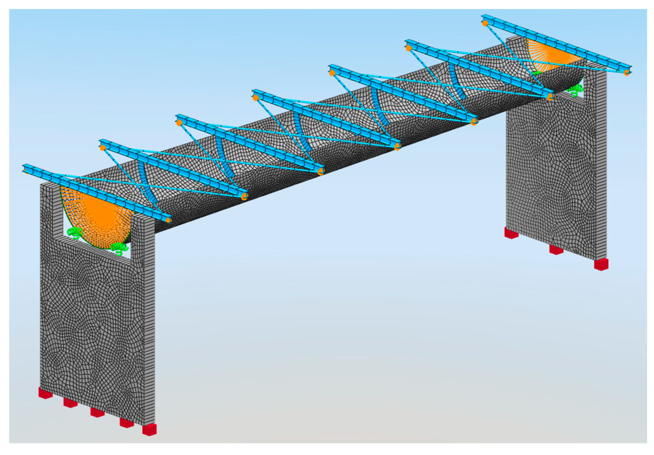
A numerical model of the bridge was created and analyzed in SOFiSTiK software version 6 [
37] to demonstrate the feasibility of this reuse application from structural point of view (
Figure 6). The main structure of the bridge, as well as the abutments, were modeled with shell elements, with a mesh density of 7 cm × 7 cm, considering fixed support at the abutment bases. It was assumed that the timber deck contributes very little to the total stiffness of the bridge, so it was excluded from the model. The transverse beams and the horizontal bracing components were modeled with beam and truss elements, respectively, assuming that they are connected with hinged connections, thus implementing moment releases at their ends. The bearings were modeled as spring, assigning appropriate stiffness in X, Y, Z directions [
38]. Finally, two rigid constrains were assigned to the nodes at the two ends of the bridge, to represent the diaphragm action of the steel plates.
All prescribed loads according to EN1991-2 [
39] were considered, including uniformly distributed live loading of 5 kN/m
2 over the entire deck and vertical concentrated loads of 5 kN on the transverse beams. The loading assumptions presented in
Section 2.2 were adopted. Wind actions were calculated assuming a basic wind velocity of 33 m/s and were modeled as line loads at the deck level. The temperature loading was considered corresponding to an air temperature differential of 20 °C, but it is not critical for such a short-span bridge resting on bearings. The seismic actions were calculated using the response spectrum method according to the elastic spectrum of EC8 for an earthquake with a return period of 475 years, considering a seismic ground acceleration of 0.16 g. The main loading combinations include ULS, SLS and construction stage loading.
2.5. Case Study 2: Storage Tank
For the second examined application, the bottom section of the tower is cut in half, transversely to the longitudinal axis of the tower, creating two frustoconical segments, each 8 m long. Each section is then utilized to form a fluid storage tank. These tanks are typically used for potable water storage, such as for residential and commercial use, as well as for agricultural purposes [
40]. Vertical water tanks have larger diameter and are used to contain fluids with low to medium viscosity; however, horizontal tanks are more appropriate for areas prone to earthquakes [
41]. In addition to the main shell, the other structural components of tanks are the heads, the saddles, the nozzles and, eventually, large inspection opening (
Figure 7).
For the present reuse application, the heads follow an ellipsoid geometry with the dimensions shown in
Figure 8, determined according to [
42]. The heads are fabricated separately and are welded to the main tank shell structure obtained from the tower section.
Horizontal tanks are supported on two saddles, which in the present study consist of flat steel plates acting as webs and curved ones acting as flanges (
Figure 9). Τhe optimal location of the saddles along the length of the tank is determined by means of simple structural considerations, to minimize flexural stresses on the tank shell [
43,
44]. It is assumed that the tank is fully filled, taking also a safety factor of 1.35 into consideration.
The nozzles are another important aspect of the design for the operation of the tank. For the examined, relatively large tank, it was decided to have two sets of nozzles, each 200 mm diameter, equipped with a strengthening steel plate of 400 mm diameter [
45], in accordance with the most common pipe diameters suited for large storage tanks [
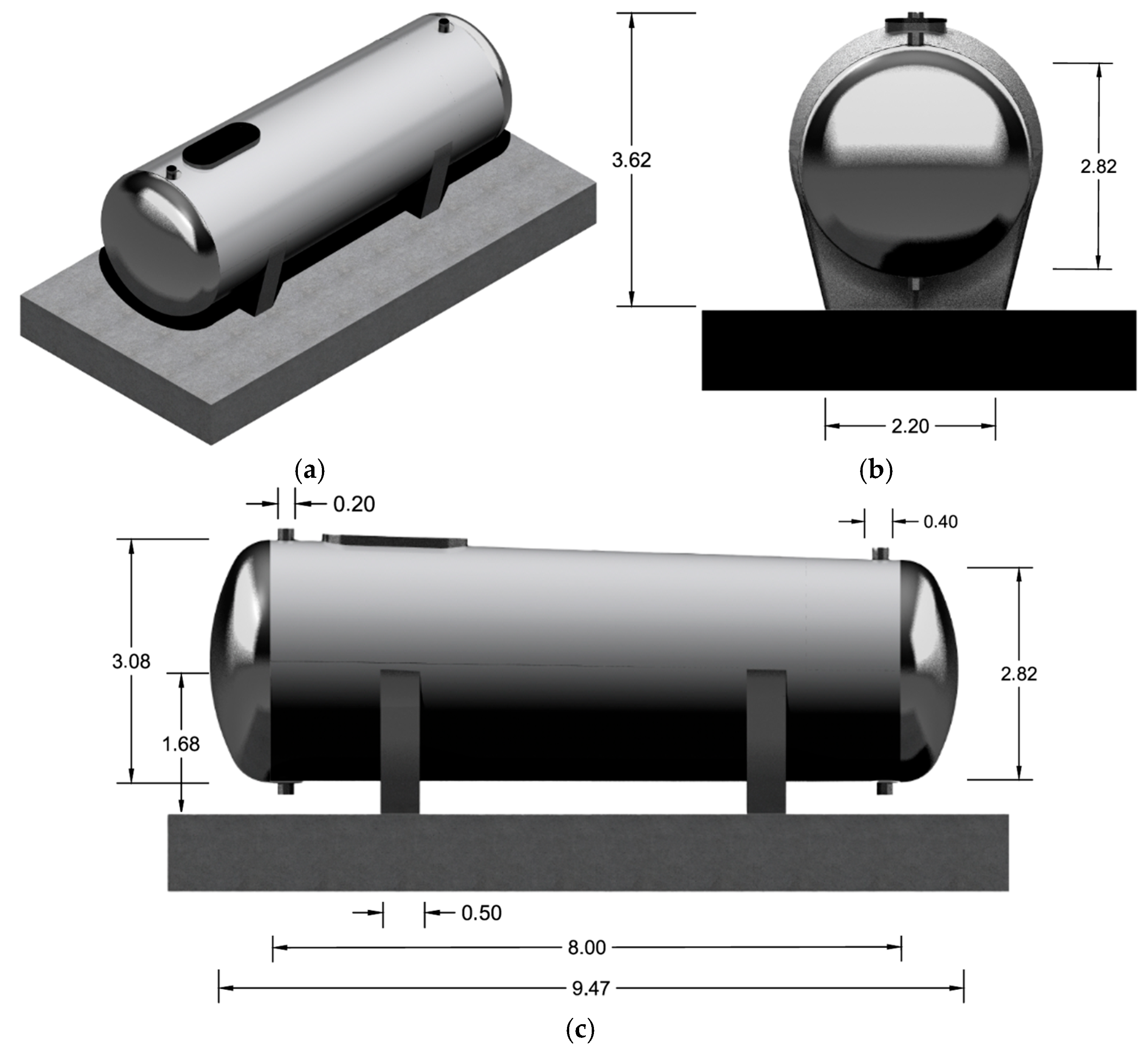
46]. In addition, the original opening and stiffening of the tower’s manhole is kept serving as an inspection opening. Illustrations and main dimensions of the storage tank are shown in
Figure 10.
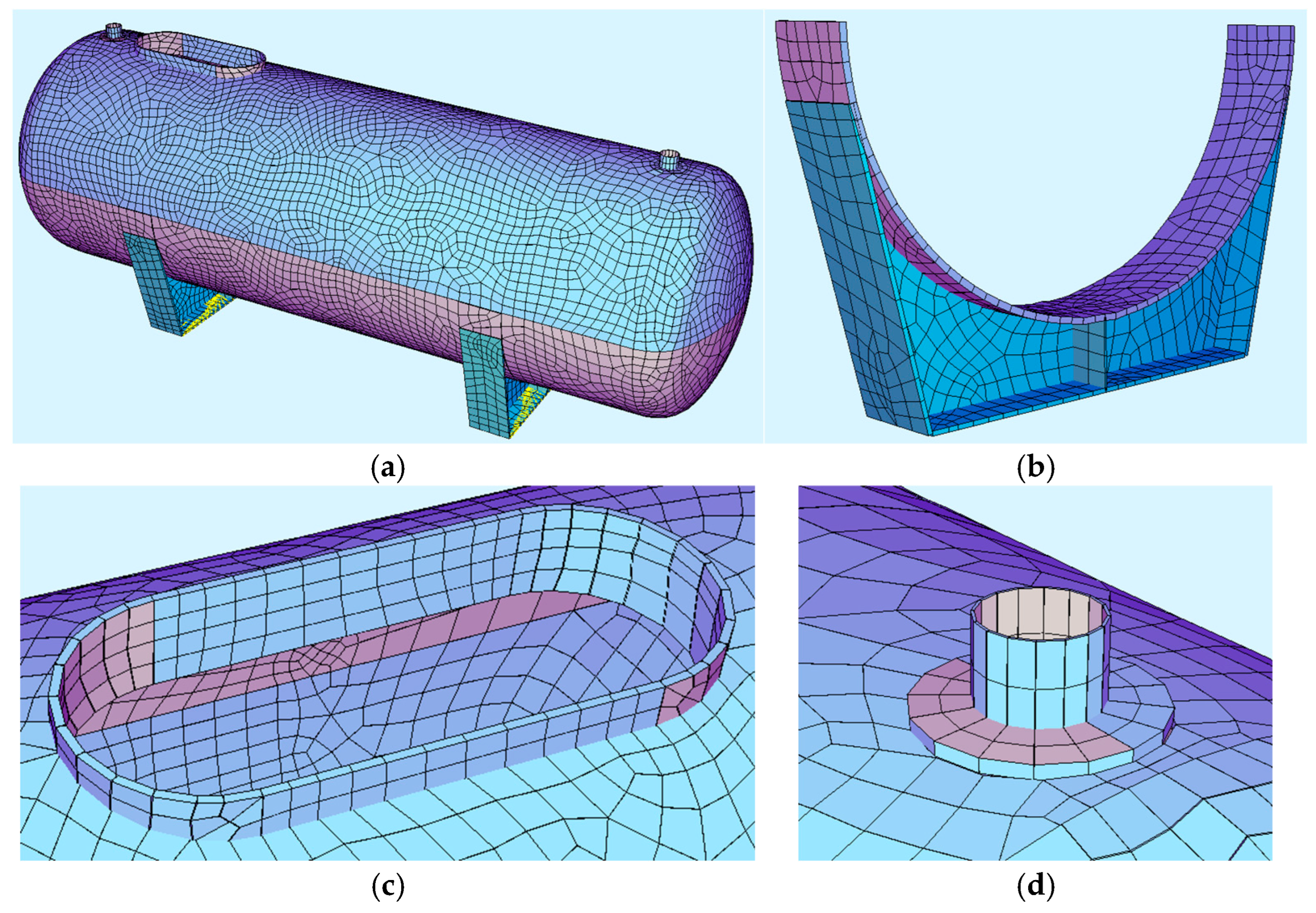
A numerical model of the tank was also developed and analyzed in SOFiSTiK software (
Figure 11), again aiming at demonstrating the feasibility of this reuse application from structural point of view, while other design aspects were analyzed qualitatively. All structural components were modeled as shell elements. The intersection of the saddles with the main vessel is intended to be welded, so the shell elements must be meshed continuously to ensure proper convergence at the interface. The tank is considered to be founded upon a thick concrete slab, as shown in
Figure 10c; however, in the model kinematic constraints were applied directly to the bottom flange of the saddle. In addition, one foot is restrained horizontally, while the other is free to slide. This is standard practice in designing steel horizontal tanks to avoid stresses due to temperature differentials. The region of the tower requiring higher accuracy was meshed more densely with elements sized at 7 cm × 7 cm, while the remaining areas were meshed using default settings. The variation in coloring is solely a result of the local axis and has no adverse impact on the results in any performed analysis.
All prescribed loads according to ASME [
47] were taken into consideration, including self-weight, hydrostatic pressure, temperature effects and wind loads from all directions. Analysis against environmental and seismic actions, like in the first case study, was conducted using the design parameters presented in
Section 2.2. Accidental loadings such as impact or penetration from forklift equipment were not considered at this preliminary design stage. Finally, a separate model was developed to analyze the tank’s behavior during lifting and was also used for dimensioning of the lifting lugs.
3. Results
3.1. Structural Evaluation of Pedestrian Bridge
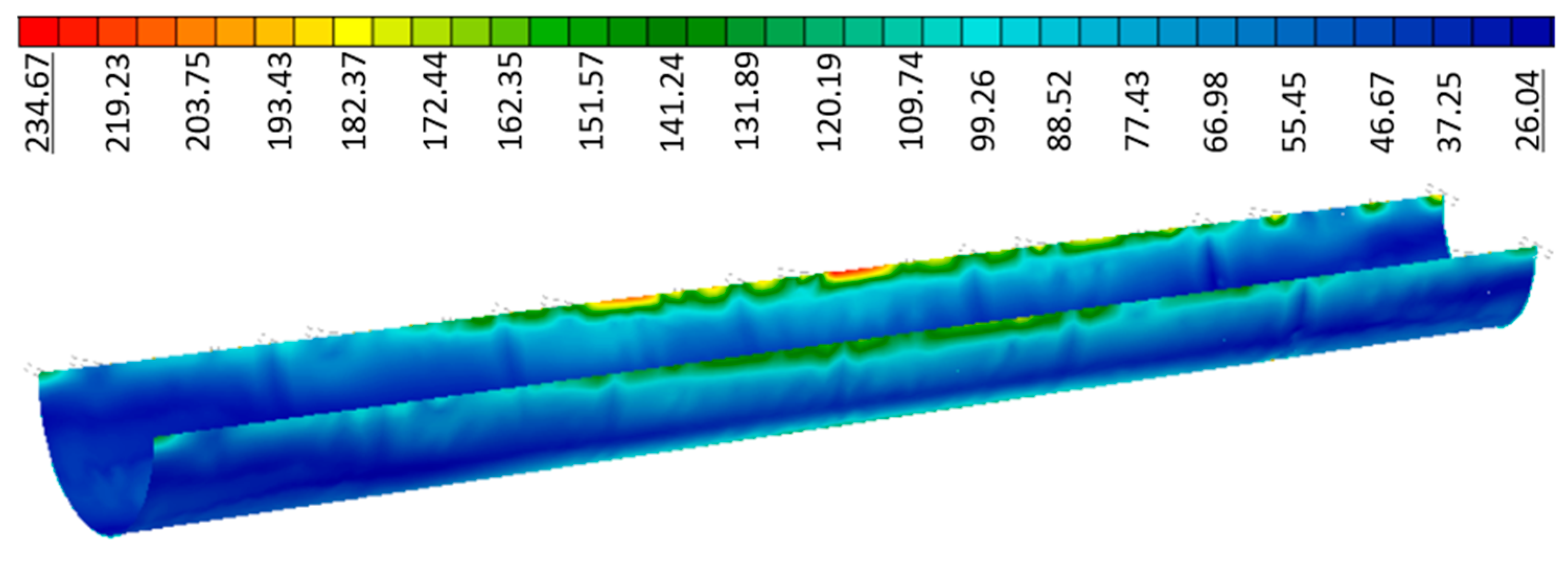
A summary of the structural analysis results and the corresponding verifications of the proposed pedestrian bridge structure are presented in this section. The structural performance of the shell-type main structure, obtained from the tower section, was evaluated by means of von Mises stresses developing under ULS load combination 1.35G + 1.50Q. Very localized stress concentrations at the supports of the transverse beams on the shell structure were observed; however, considering also the provided stiffeners, the stress levels remain within acceptable limits, reaching 235 MPa (
Figure 12), offering a sufficient safety margin compared to the considered yield strength of 260 MPa. Appropriate connection details will be configured during final design, by means of which these stress concentrations will be avoided, however this is beyond the scope of the present preliminary structural evaluation.
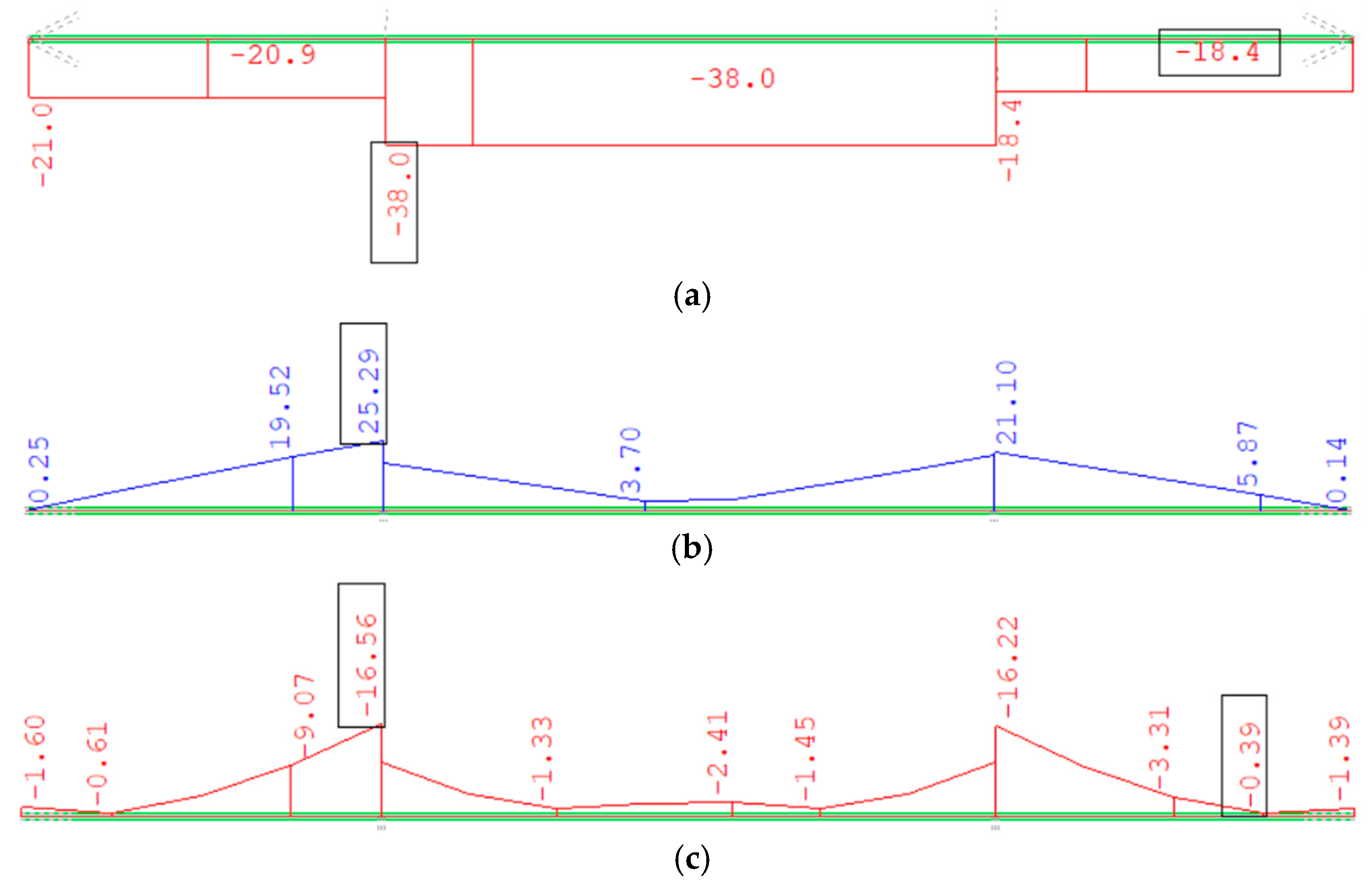
The transverse beams are subjected to axial forces, shear forces, and bending moments (
Figure 13), and they have been checked for these combined effects according to Eurocode 3 [
48], including verification against lateral-torsional buckling, conservatively neglecting any lateral restraint provided by the deck. The highest utilization level was found to be 85%. Horizontal bracing elements were checked against axial force, including flexural buckling, with maximum utilization level of 48%.
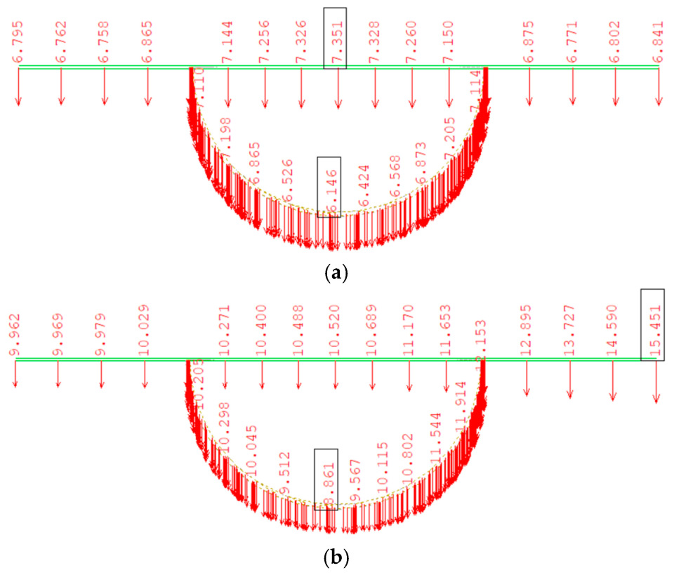
For the deformation check under SLS load combinations, the deflections from permanent and live loads are presented in
Figure 14, indicating a very stiff response of the main structure, as expected, with a maximum deflection of less than 10 mm, in the order of span over 1500. The response of the transverse beams is equally stiff, with a maximum deflection in the frequent load combination (G + 0.75Q) observed at the edge of the transverse beams, due to the local effect of the concentrated load, and a relative deflection at midspan of less than 2 mm, also in the order of span over 1500.
The seismic response check was performed using the response spectrum method and assuming that the bridge behaves fully elastically with a behavior factor q = 1. The load combination used is G + 0.20Q, where “G” is the permanent loads and “Q” the live loads, assuming that 20% of the live load is present during the seismic event.
The first two mode shapes are illustrated in
Figure 15, with corresponding periods of vibration equal to 0.90 s and 0.85 s, respectively, while the third mode is substantially stiffer, with a period of 0.51 s. The modes are dominated by the deformation of the bearings and illustrated in exaggerated scale of deformations, where the brighter color indicates larger displacement, due to which the main structure appears to deform outside of the abutments. As expected, seismic actions are not critical for the steel superstructure.
Evaluating the proposed design in terms of material usage and CO
2 emissions, the steel superstructure of the bridge weighs 6.1 t, which corresponds to approximately 0.08 t per m
2 of bridge deck, similar to what would have been expected for a pedestrian bridge of this span and width with a more conventional structural system [
49]. The reused tower section weighs 4.6 t, raising the share of reused material to approximately 75%. As of 2025, steel manufacturing emits approximately 1.7 t CO
2 per ton of steel [
11], depending on the production method. Therefore, the tower section alone would correspond to roughly 7.8 t CO
2 if newly produced. However, this figure should not be interpreted as the actual CO
2 emission reduction but should only be seen as an initial indicator of potential CO
2 emission savings. Additional fabrication processes for adapting the reused wind turbine sections—such as cutting and jointing—will slightly increase emissions. On the other hand, extending the service life of the tower reduces its overall carbon footprint across its lifecycle. Ultimately, such considerations should be addressed through a comprehensive lifecycle assessment, which lies beyond the scope of this study.
3.2. Structural Evaluation of Water Tank
A summary of the structural analysis results and the corresponding verifications of the proposed water tank are presented in this section. The maximum von Mises stresses of the main tank shell, fabricated from the tower section and considered to have a yield stress of 260 MPa, were calculated to be 160 MPa due to the most unfavorable ULS static combination, and are presented in
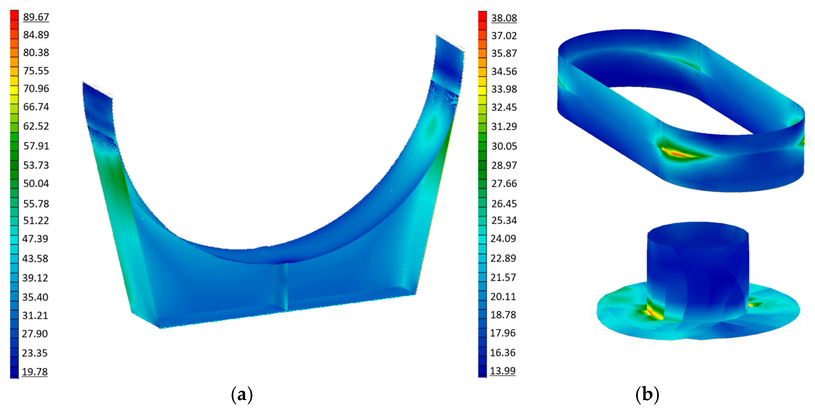
Figure 16. Stress peaks are encountered only at the edges of the saddles, while average stresses are much lower, exhibiting high safety margins. The saddles, heads, and nozzles are fabricated from new S235 grade steel. The corresponding stress distributions are shown in
Figure 17, being also generally lower than 100 MPa.
Due to its significant mass when fully filled, the tank must also be evaluated for seismic actions [
50,
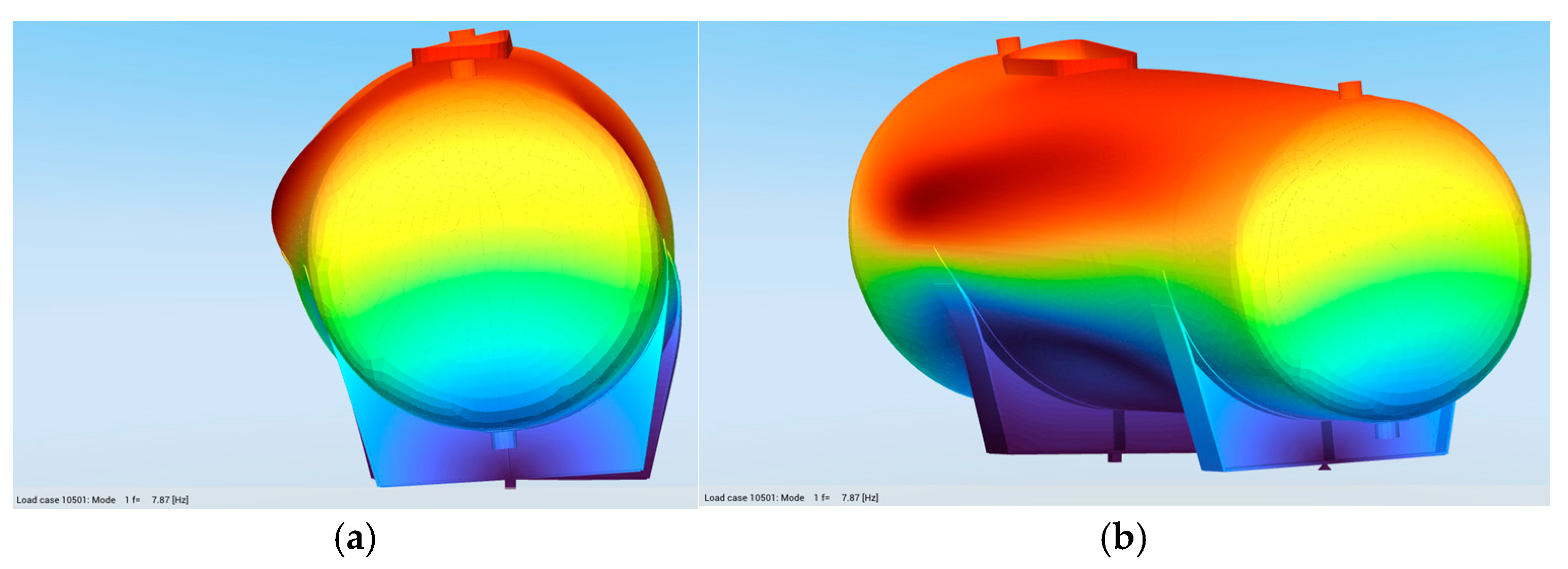
51]. A response-spectrum analysis was conducted for that purpose. The fundamental mode of vibration of the tank is illustrated in
Figure 18, where the blue color stands for little to no displacement and the bright red corresponds to maximum displacement. The maximum von Mises stresses in the tank from seismic combinations were higher than the static ones, reaching approximately 200 MPa (
Figure 19), yet still well below the yield strength, and also appearing only locally around the edges of the saddles.
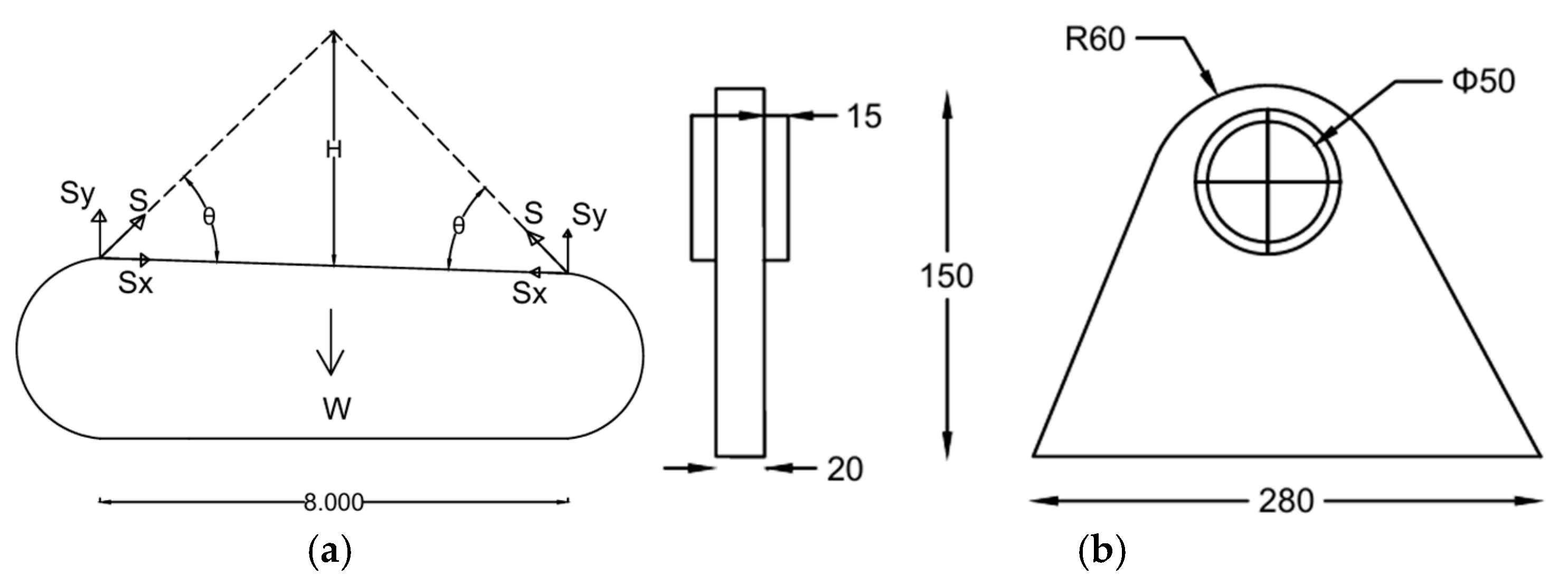
Lifting of the tank for transportation and placement is addressed with a separate analysis model (
Figure 20a) with appropriate boundary conditions corresponding to two pairs of lugs near the head areas, considering only the self-weight of the empty tank, equal to 145.7 kN, with an amplification factor of 1.50. The lifting lugs were dimensioned and checked for combined tension and shear, as well as weld integrity [
52], assuming a vertical height of the chains in the range from 1.00 m to 3.00 m and optimizing their geometry accordingly (
Figure 20b).
The lugs were incorporated in the numerical model using shell finite elements, while the chains were represented as truss elements (
Figure 21a). To improve the stress distribution on the tank’s surface, 300 mm × 300 mm × 20 mm steel plates were added as support bases for the lugs, as shown in
Figure 21b. The obtained results are presented in
Figure 21c,d. The maximum localized stresses in the support plate and the lug were obtained around 100 MPa and 230 MPa, respectively.
Under the current design, the storage tank exhibits a utilization factor of up to 76%, which is typical for preliminary structural designs, where target utilization values usually range between 75% and 80%. Considering, however, the lower average stresses, smaller wall thicknesses would be expected in a newly designed and structurally optimized tank. Consequently, a part of the mass of the reused wind turbine tower section can be considered as material savings. As the mass of the reused tower section is again 4.6 t, an estimated reduction of around 5 t of CO2 emissions is expected.
Moreover, reuse of the tower section is expected to significantly reduce emissions and costs associated with fabrication in this case. Manufacturing a new storage tank typically involves substantial welding, assembly, and modular construction, which are labor-intensive processes, particularly for the tank shell, which is the largest and a quite complex component. By repurposing an existing tower section as the tank shell, only the heads, saddles, and nozzles need to be fabricated, thereby shortening the construction process, reducing labor effort, and minimizing both direct manufacturing costs and erection time.
4. Discussion
As demonstrated by the above analysis, the reused tower parts exhibit satisfactory structural behavior in their new use, either as the main structure of a pedestrian bridge or as a water storage tank, satisfying the required verifications under the loading conditions prescribed by pertinent codes and considering the specified safety factors. Technical details for both case studies are provided in the diploma thesis of the first author [
53].
Considering the results of both case studies, the estimated von Mises stresses are overall safely below the material’s yield limit but close enough at some areas where localized stress concentrations occur. As the adopted approach would correspond to a preliminary design level to act as a feasibility study, local strengthening and proper connection detailing that may be necessary in order to address stress violations will be addressed in future studies. The same holds for buckling and fatigue verifications, which however are not expected to be critical for the selected applications.
The need to develop analytical design approaches for reuse, similar to the existing ones for new steel structures, is highlighted. While it is rightly discussed that, in the context of reuse, fatigue loads should be avoided, attention must also be paid to the issue of buckling. This may also serve as an additional criterion for the new use, especially in cases where there is limited capability to record the actual geometry and the existing imperfections. In such cases, appropriate measures should be taken. Further research, with the aim to enhance reuse of steel and increase modularity, could indicate possible acceptable solutions for enhancing buckling stability or fatigue resistance of reused components. Along these lines, a pertinent research objective may be to propose appropriate buckling curves for reused components, considering imperfections from manufacturing and service.
It should be noted that the reuse applications proposed in the present study are not subjected to significant fatigue loading. Pedestrian bridges intended for low-traffic use are exempt from fatigue verification requirements due to the limited number of load cycles they experience, while the storage tank is designed for predominantly static loading, being filled and emptied only over long intervals. Therefore, a detailed fatigue life assessment of the reused tower sections is deemed unnecessary for these specific cases.
Regarding durability, the condition of the existing corrosion protection coatings must be evaluated prior to reuse. Depending on the results, engineers may either recoat the tower or, where material utilization is low, allow for a controlled sacrificial wall thickness without additional coating, as is also permitted in modern structural design codes for certain structural elements (see for instance Eurocode 3, Part 5). While recoating can extend service life, it also entails additional cost and embodied carbon emissions, which must be weighed against the actual durability demands of the new application. The targeted reuse and specific requirements (for instance the storage of potable water or other fluid in the tank) should also be a decision factor.
Alternative reuse applications for wind turbine towers are also possible, including uses as steel silos, structures designed to store bulk solids such as grains [
54,
55,
56], which share a similar geometry with wind turbine towers, and allow material flowing out by gravity without the need for additional equipment. Another possible application is as a steel chimney to ensure the smooth transfer of hot exhaust gases and smoke from their source to the atmosphere, in compliance with specific environmental regulations [
57].
Regarding other components of wind turbine towers, while substantial research has been conducted on reuse of the blades, no satisfactory solutions have been proposed for the wind turbine’s heaviest component, the reinforced concrete foundation. One possible solution, since concrete is made up of inert materials, is to crush it into as fine a material as possible and add it to a new concrete mix. While the reuse of the tower may offer combined economic and environmental benefits, for the foundation the advantages are primarily environmental.
5. Conclusions
A significant number of first-generation wind turbine towers are reaching the end of their design life, and direct reuse offers an attractive alternative to energy-intensive recycling. This study demonstrated the feasibility of reusing tubular steel tower sections in two representative applications—a pedestrian bridge and a water storage tank. In both cases, even with a conservatively reduced yield strength of 260 MPa, the repurposed sections satisfied the basic structural verifications under relevant codes, showing acceptable stress levels and deflections.
From a structural safety perspective, the results showed that the repurposed sections satisfy ultimate and serviceability limit state checks, with acceptable stress levels and deflections under static, wind, and seismic actions. Fatigue verification, a critical design criterion for wind turbine towers during their operational life, was not required in these new applications since the loading regimes are predominantly static or involve very low cycle counts (e.g., occasional pedestrian traffic or long filling intervals for the tank). Nevertheless, considerations for local reinforcement or connection detailing may be necessary in future implementations, particularly in regions of stress concentration or where geometry modifications are required.
The reuse resulted in notable material savings, as follows: for both applications, about 4.6 t of steel were preserved, avoiding approximately 7.8 t CO2 emissions. Additionally, the fabrication process was simplified, as the most labor-intensive part (the cylindrical shell) was already available, reducing both manufacturing effort and construction time.
Beyond structural feasibility, logistics aspects such as disassembly, transportation, and adaptation of the tower sections were also qualitatively considered and found to be manageable with standard equipment and procedures, further supporting the practical viability of reuse. Site selection, handling constraints, and transportation distances can influence the overall economic and environmental benefits, indicating that careful planning is essential for large-scale adoption.
The study highlights that wind turbine towers are well suited for secondary use in infrastructure, particularly when fatigue is no longer critical, as in low-traffic pedestrian bridges or static tanks. However, further research is needed to develop standardized inspection, testing, and buckling assessment protocols for reused steel sections and to evaluate their full environmental and economic benefits through life-cycle analyses. Overall, these findings confirm that reuse can significantly extend the material’s life cycle, reduce embodied carbon, and contribute to circular economy goals, offering a sustainable complement to conventional steel recycling.
Author Contributions
Conceptualization, C.J.G. and B.L.; methodology, C.J.G. and S.G.; software, S.S.; validation, C.J.G. and S.S.; investigation, C.J.G. and S.S.; resources, C.J.G. and S.S.; data curation, S.S.; writing—original draft preparation, S.S.; writing—review and editing, C.J.G. and S.G.; visualization, S.S.; supervision, C.J.G.; project administration, C.J.G. All authors have read and agreed to the published version of the manuscript.
Funding
This research received no external funding.
Data Availability Statement
The data used in the study are available with the authors and can be shared upon reasonable request.
Acknowledgments
Appreciation is expressed to the Center of Renewable Energy Sources and Savings for providing information regarding old models of wind turbines, the service of the tower, and technical drawings, as well as photographic material.
Conflicts of Interest
The authors declare no conflicts of interest.
References
- Supriyanti, L. World of Steel: Economic & Social Impact of the Steel Industry, 23 February 2023. Available online: https://liwasupriyanti.com/world-of-steel-economic-social-impact-of-the-steel-industry/ (accessed on 30 July 2025).
- Cornwall, W. Steel industry emissions are a big contributor to climate change. Can it go green? Science 2024, 384, 498–499. [Google Scholar] [CrossRef]
- Guillot, J.D. Circular Economy: Definition, Importance and Benefits; European Parliament: Brussels, Belgium, 2023. [Google Scholar]
- Grosvenor Some of UK’s First Salvaged Steelwork Reused in Holbein Gardens Retrofit. Available online: https://www.grosvenor.com/news-insights/some-of-uk%E2%80%99s-first-salvaged-steelwork-reused-in-holbein-gardens-retrofit (accessed on 31 May 2024).
- Schütz, D. Use of steel scrap saves billions in climate and environmental costs. Recycling Magazine, 25 March 2020. Available online: https://www.recycling-magazine.com/2020/03/25/use-of-steel-scrap-saves-billions-in-climate-and-environmental-costs/ (accessed on 30 July 2025).
- Puma, C.; Salles, A.; Turk, J.; Ungureanu, V.; Bragança, L. Utilisation of Reused Steel and Slag: Analysing the Circular Economy Benefits through Three Case Studies. Buildings 2024, 14, 979. [Google Scholar] [CrossRef]
- Hao, H.; Wu, H.; Wei, F.; Xu, Z.; Xu, Y. Scrap Steel Recycling: A Carbon Emission Reduction Index for China. Sustainability 2024, 16, 4250. [Google Scholar] [CrossRef]
- Brown, D.G.; Pimentel, R.J.; Sansom, M.R. Structural Steel Reuse: Assessment, Testing and Design Principles; The Steel Construction: Ascot, UK, 2019; ISBN 978-1-85942-243-4. [Google Scholar]
- Katenbayeva, A. Projects on Steel Reuse. In DISRUPT II; ASBP: London, UK, 2024. [Google Scholar]
- Dietsch, P.; Müller, M.; Frese, M.; Ehrenlechner, C.; Mensinger, M.; Winter, S.; Ummenhofer, T. Guidelines for the Reuse of Bearing Structural Components; KIT & TUM: Karlsruhe, Germany, 2025; p. 44. [Google Scholar]
- Suer, J.; Traverso, M.; Jäger, N. Review of Life Cycle Assessments for Steel and Environmental Analysis of Future Steel Production Scenarios. Sustainability 2022, 14, 14131. [Google Scholar] [CrossRef]
- Australian Steel Institute Steel Costing-Multi-Level Construction. Available online: https://www.steel.org.au/what-we-do/focus-areas/steel-in-buildings/steel-costing-multi-level-construction/ (accessed on 27 September 2024).
- Feldmann, M.; Bartsch, H.; Eyben, F.; Bours, A.-L.; Knobloch, M. Establishing European design rules for re-used steel components. Steel Constr. 2024, 17, 57–69. [Google Scholar] [CrossRef]
- Kah, P.; Martikainen, J.; Layus, P. Methods of Evaluating Weld Quality in Modern Production (Part 1). In Proceedings of the 16th International Conference, Mechanika, Kaunis, Lithuania, 7–8 April 2011; p. 7. [Google Scholar]
- Pavlina, E.J.; Van Tyne, C.J. Correlation of Yield Strength and Tensile Strength with Hardness for Steels. J. Mater. Eng. Perform. 2008, 17, 888–893. [Google Scholar] [CrossRef]
- Hughbanks, C. NDT Testing for Steel Construction 2022. Available online: https://metsuco.com/ndt-testing-for-steel-construction/?srsltid=AfmBOopOjUFBLMvDmA7ocktP2jiy3qruyAfVKZB5dZnSpZqpQc01j87S (accessed on 30 July 2025).
- Alhassan, M.; Bashiru, Y. Carbon Equivalent Fundamentals in Evaluating the Weldability of Microalloy and Low Alloy Steels. World J. Eng. Technol. 2021, 9, 782–792. [Google Scholar] [CrossRef]
- Fujita, M.; Kuki, K. An Evaluation of Mechanical Properties with the Hardness of Building Steel Structural Members for Reuse by NDT. Metals 2016, 6, 247. [Google Scholar] [CrossRef]
- Ghenai, C. Life Cycle Analysis of Wind Turbine. In Sustainable Development–Energy, Engineering and Technologies–Manufacturing and Environment; Ghenai, C., Ed.; InTech: London, UK, 2012; ISBN 978-953-51-0165-9. [Google Scholar]
- Delaney, E.L.; Leahy, P.G.; McKinley, J.M.; Gentry, T.R.; Nagle, A.J.; Elberling, J.; Bank, L.C. Sustainability Implications of Current Approaches to End-of-Life of Wind Turbine Blades—A Review. Sustainability 2023, 15, 12557. [Google Scholar] [CrossRef]
- National Grid Can Wind Turbine Blades Be Recycled? Available online: https://www.nationalgrid.com/stories/energy-explained/can-wind-turbine-blades-be-recycled (accessed on 19 February 2025).
- Harvey, L.D.D. Iron and steel recycling: Review, conceptual model, irreducible mining requirements, and energy implications. Renew. Sustain. Energy Rev. 2021, 138, 110553. [Google Scholar] [CrossRef]
- Jones, K.-E.S.; Li, M. Life cycle assessment of ultra-tall wind turbine towers comparing concrete additive manufacturing to conventional manufacturing. J. Clean. Prod. 2023, 417, 137709. [Google Scholar] [CrossRef]
- Wood, D. Small Wind Turbines: Analysis, Design, and Application; Green Energy and Technology; Springer: London, UK, 2011; ISBN 978-1-84996-174-5. [Google Scholar]
- Swanton Weldng Company Different Types of Wind Turbine Towers Made with Steel. Available online: https://swantonweld.com/steel-wind-turbine-towers/ (accessed on 12 February 2024).
- Zou, T.; Niu, X.; Ji, X.; Li, M.; Tao, L. The impact of initial imperfections on the fatigue assessment of tower flange connections in floating wind turbines: A review. Front. Mar. Sci. 2022, 9, 1063120. [Google Scholar] [CrossRef]
- Forsberg, T.; Behrndt Ebbesen, N.; Henriksen, J. Re-use of wind turbine steel towers for pedestrian bridges. In Proceedings of the IABSE Symposium Manchester 2024, Manchester, UK, 10–12 April 2024; pp. 1285–1294. [Google Scholar]
- Johst, P.; Chatzipanagiotou, K.-R.; Kucher, M.; Zschiebsch, W.; Voigt, P.; Breinl, D.; Koumoulos, E.P.; Böhm, R. Concept and Life Cycle Assessment of a Tiny House Made from Root Section Structures of a Decommissioned Large-Scale Wind Turbine Blade as a Repurposed Application. Mater. Circ. Econ. 2024, 6, 5. [Google Scholar] [CrossRef]
- André, A.; Kullberg, J.; Nygren, D.; Mattsson, C.; Nedev, G.; Haghani, R. Re-use of wind turbine blade for construction and infrastructure applications. IOP Conf. Ser. Mater. Sci. Eng. 2020, 942, 012015. [Google Scholar] [CrossRef]
- Center for Renewable Energy Sources and Savings Wind Turbines. Available online: http://www.cres.gr/kape/energeia_politis/energeia_politis_windmill_eng.htm (accessed on 26 April 2025).
- Center for Renewable Energy Sources and Savings 3.01 MW Demonstration Wind Farm. Available online: http://www.creswindfarm.gr/site1/index_en.htm (accessed on 21 March 2025).
- AutoCAD; Autodesk: Amsterdam, The Netherlands, 2025.
- Luo, N.; Zhou, T.; Zhang, C. Mechanical properties of Q345 structural steel after pre-fatigue loading. Structures 2023, 56, 104944. [Google Scholar] [CrossRef]
- Li, Y.; Chi, Q.; Ben, Y.; Ji, L.; Feng, H.; Chen, H. Effect of Strain Aging on Properties of X90 Line Pipe. Procedia Struct. Integr. 2019, 22, 118–124. [Google Scholar] [CrossRef]
- Mazzolani, F.M.; Dubina, D.; Stratan, A. (Eds.) Proceedings of the 10th International Conference on Behaviour of Steel Structures in Seismic Areas: STESSA 2022; Lecture Notes in Civil Engineering; Springer International Publishing: Cham, Switzerland, 2022; Volume 262, ISBN 978-3-031-03810-5. [Google Scholar]
- Rhino3D; Robert McNeel & Associates (TLM, Inc.): Seattle, WA, USA, 2024.
- SOFiSTiK AG; Sofistik: Nuremberg, Germany, 2025.
- Elastomeric Bearings; Freyssinet: Wellington, New Zealand, 2019.
- EN 1991-2:2003; Eurocode 1: Actions on Structures—Part 2: Traffic Loads on Bridges. Eurocodes: Brussels, Belgium, 2003.
- GSC Tanks Large Above Ground Horizontal Storage Tanks: What They Typically Hold. Available online: https://www.gsctanks.com/what-do-large-above-ground-horizontal-storage-tanks-typically-hold/ (accessed on 20 February 2025).
- ZWIRNER EQUIPMENT COMPANY Vertical vs. Horizontal Storage Tanks 2023. Available online: https://www.zwirnerequipment.com/blog/vertical-vs-horizontal-storage-tanks/ (accessed on 30 July 2025).
- PV ENG Comparison Between Head Types: Hemi, SE, F&D and Flat. Available online: https://www.pveng.com/home/asme-code-design/comparison-between-head-types-hemi-se-fd-and-flat/ (accessed on 30 July 2025).
- Khan, S.-M.A. Stress distributions in a horizontal pressure vessel and the saddle supports. Int. J. Press. Vessel. Pip. 2010, 87, 239–244. [Google Scholar] [CrossRef]
- Kumar, V.; Kumar, N.; Angra, S.; Sharma, P. Design of Saddle Support for Horizontal Pressure Vessel. Int. Sch. Sci. Res. Innov. 2014, 8, 1965–1969. [Google Scholar]
- Anup, K.D. Considerations for Storage Tanks Nozzles Orientation. Available online: https://whatispiping.com/guides-for-storage-tanks-nozzles-orientation/ (accessed on 13 June 2024).
- SARRZ Nozzles, Nipples, Connecting Pipes, Fittings. Available online: https://sarrz.com/product_line/tank_equipment/nozzles.html (accessed on 23 April 2025).
- American Society of Mechanical Engineers (ASME). Boiler and Pressure Vessel Code an International Code, 5th ed.; BPVC: New York, NY, USA, 2023. [Google Scholar]
- EN 1993; Eurocode 3: Design of Steel Structures—Part 1-1: General Rules and Rules for Buildings. Eurocodes: Brussels, Belgium, 2007.
- Bogahawaththa, P.B.M.R.; Hidallana-Gamage, H.D.; Baskaran, K. Investigate an economical truss type steel pedestrian bridge for Sri Lanka. In Proceedings of the International Conference on Civil Engineering and Applications (ICCEA-2019), Seoul, Republic of Korea, 21–23 September 2019. [Google Scholar]
- Fiore, A.; Rago, C.; Vanzi, I.; Greco, R.; Briseghella, B. Seismic behavior of a low-rise horizontal cylindrical tank. Int. J. Adv. Struct. Eng. 2018, 10, 143–152. [Google Scholar] [CrossRef]
- Lyu, Y.; Sun, J.; Sun, Z.; Cui, L.; Wang, Z. Simplified mechanical model for seismic design of horizontal storage tank considering soil-tank-liquid interaction. Ocean Eng. 2020, 198, 106953. [Google Scholar] [CrossRef]
- Universal Engineering Consultants Lifting Lug Design 2021. Available online: https://www.universalengineeringconsultants.com/post/lifting-lug-design-using-pv-elite-ues-ues (accessed on 30 July 2025).
- Sideris, S. Examples of Wind Turbine Tower Reuse. Integrated. Master’s Thesis, National Technical University of Athens, Athens, Greece, 2024. Available online: https://dspace.lib.ntua.gr/xmlui/handle/123456789/61638 (accessed on 30 July 2025).
- Popiel, A. Silosy stalowe. Builder 2019, 263, 80–82. [Google Scholar] [CrossRef]
- Sagarnaga, J.C. Basics of Silo Design Engineering; Boston Society of Civil Engineers Section (BSCES): Boston, MA, USA, 2023. [Google Scholar]
- Dornelas, K.C.; Bandeira, D.J.A.; Rodrigues, R.C.M.; Arruda, T.R.; Filho, W.L.D.S.; Lima, M.J.N.D.C.; Figueiredo, C.F.V. Flow properties for silo design—A review. Int. J. Dev. Res. 2022, 12, 57772–57777. [Google Scholar] [CrossRef]
- Verboom, G.K.; Van Koten, H. Vortex excitation: Three design rules tested on 13 industrial chimneys. J. Wind Eng. Ind. Aerodyn. 2010, 98, 145–154. [Google Scholar] [CrossRef]
Figure 1.
Flow chart of the reuse methodology.
Figure 1.
Flow chart of the reuse methodology.
Figure 2.
NEG MICON 750 kW wind turbine located at CRES windfarm in Lavrio.
Figure 2.
NEG MICON 750 kW wind turbine located at CRES windfarm in Lavrio.
Figure 3.
Main geometric data of the NEG MICON 750 kW tower (dimensions in mm).
Figure 3.
Main geometric data of the NEG MICON 750 kW tower (dimensions in mm).
Figure 4.
Three-dimensional representation of the conceptualized pedestrian bridge: Exploded view showing the main structural components.
Figure 4.
Three-dimensional representation of the conceptualized pedestrian bridge: Exploded view showing the main structural components.
Figure 5.
Illustrations of the bridge: (a) isometric view, (b) front view and (c) side view (dimensions in mm).
Figure 5.
Illustrations of the bridge: (a) isometric view, (b) front view and (c) side view (dimensions in mm).
Figure 6.
Numerical model of pedestrian bridge.
Figure 6.
Numerical model of pedestrian bridge.
Figure 7.
Structural components of the vessel.
Figure 7.
Structural components of the vessel.
Figure 8.
Ellipsoid geometry of the heads at the ends of the tank (dimensions in meters).
Figure 8.
Ellipsoid geometry of the heads at the ends of the tank (dimensions in meters).
Figure 9.
Positions (a) and geometry (b) of the saddles (dimensions in meters).
Figure 9.
Positions (a) and geometry (b) of the saddles (dimensions in meters).
Figure 10.
Illustrations of the tank: (a) isometric view, (b) front view and (c) side view (dimensions in meters).
Figure 10.
Illustrations of the tank: (a) isometric view, (b) front view and (c) side view (dimensions in meters).
Figure 11.
Numerical model of the water tank: (a) full model, (b) details of saddles, (c) opening and stiffening and (d) nozzles.
Figure 11.
Numerical model of the water tank: (a) full model, (b) details of saddles, (c) opening and stiffening and (d) nozzles.
Figure 12.
Maximum von Mises stresses (MPa) of the main structure of the bridge in ULS.
Figure 12.
Maximum von Mises stresses (MPa) of the main structure of the bridge in ULS.
Figure 13.
Indicative action effects of transverse beams: (a) axial forces (kN), (b) shear forces (kN), and (c) bending moments (kNm).
Figure 13.
Indicative action effects of transverse beams: (a) axial forces (kN), (b) shear forces (kN), and (c) bending moments (kNm).
Figure 14.
Deflections (mm): (a) from quasi-permanent loading combination and (b) from the most unfavorable frequent loading combination.
Figure 14.
Deflections (mm): (a) from quasi-permanent loading combination and (b) from the most unfavorable frequent loading combination.
Figure 15.
First two vibration modes of the bridge: (a) 1st mode (longitudinal) and (b) 2nd mode (transverse).
Figure 15.
First two vibration modes of the bridge: (a) 1st mode (longitudinal) and (b) 2nd mode (transverse).
Figure 16.
Maximum von Mises stresses (MPa) in the tank wall due to ULS load combinations.
Figure 16.
Maximum von Mises stresses (MPa) in the tank wall due to ULS load combinations.
Figure 17.
Local von Mises stress distributions due to ULS load combinations: (a) at the saddles and (b) at the stiffener and nozzle.
Figure 17.
Local von Mises stress distributions due to ULS load combinations: (a) at the saddles and (b) at the stiffener and nozzle.
Figure 18.
Fundamental mode of vibration of tank: (a) front view and (b) perspective view.
Figure 18.
Fundamental mode of vibration of tank: (a) front view and (b) perspective view.
Figure 19.
von Mises stress distribution of the tank wall due to seismic actions.
Figure 19.
von Mises stress distribution of the tank wall due to seismic actions.
Figure 20.
Lifting lugs: (a) position and (b) geometry (dimensions in mm).
Figure 20.
Lifting lugs: (a) position and (b) geometry (dimensions in mm).
Figure 21.
Lifting operation: (a) numerical model, (b) detail of the lifting lugs, (c) stress distribution in the lugs (d) stress distribution in the tank wall.
Figure 21.
Lifting operation: (a) numerical model, (b) detail of the lifting lugs, (c) stress distribution in the lugs (d) stress distribution in the tank wall.
| Disclaimer/Publisher’s Note: The statements, opinions and data contained in all publications are solely those of the individual author(s) and contributor(s) and not of MDPI and/or the editor(s). MDPI and/or the editor(s) disclaim responsibility for any injury to people or property resulting from any ideas, methods, instructions or products referred to in the content. |
© 2025 by the authors. Licensee MDPI, Basel, Switzerland. This article is an open access article distributed under the terms and conditions of the Creative Commons Attribution (CC BY) license (https://creativecommons.org/licenses/by/4.0/).
