1. Introduction
Silos filled with granular solid are exposed to particular horizontal and vertical loading conditions during seismic events that are still not fully understood [
1,
2,
3]. Two main open questions remain insufficiently addressed by the current state of knowledge in the field of the dynamic and seismic response of silos: (1) the fundamental period of the filled silo structure, as no current formula is available to even roughly estimate this value; and (2) the seismic effective mass (i.e., global response), along with the corresponding seismic additional pressure or dynamic overpressure (i.e., local response) [
3]. Earthquake excitation induces additional, non-uniform dynamic pressures on the silo wall. In circular silos, these pressures result in radial and circumferential forces acting on the wall, as well as vertical forces in the stiffeners, if present. Unlike the static equilibrium problem well-established in the 19th century [
4,
5], the dynamic equilibrium problem was investigated for the first time during the 1970s and 1980s by Wood [
6,
7] and Trahair [
8], resulting in a simple formula describing a uniform profile of the horizontal dynamic overpressure along the height of the silo wall. Different numerical and experimental investigations were devoted to understanding the suitability of this formula (e.g., Rotter and Hull, 1989 [
9]), which is currently explicitly referred to by the American FEMA P-2082-1/2020 standard [
10]. The European standard EN1998-4:2006 [
11] gives a formula that, even without explicitly making reference to the Wood and Trahair one, can be traced back to it at least for the original rectangular silo case. It is worth noticing that all other international codes do not even provide formulas for the seismic overpressures on the silo wall [
3]. This lack of a robust formulation, along with the reliance on simplified models originally proposed in earlier research, stems from the intrinsic difficulty of capturing the peculiar features of silo structures—particularly those related to the granular nature of the stored material—which cause their seismic behavior to differ significantly from that of other, seemingly similar structures, such as liquid storage tanks [
12], and even more so from conventional building structures [
13,
14,
15].
Significant attention has recently been given to the dynamic and seismic response of silos, particularly at numerical and experimental levels, with very few studies addressing it analytically. A comprehensive review of the main open questions on the dynamic and seismic response of ground-supported silos (mainly: the fundamental period of vibration and the damping ratio, as well as the effective mass and the corresponding seismic overpressures) can be found in [
3] by the same authors. Another recent wide review regarding the structural behavior and failure modes of ground-supported and elevated silos (i.e., their response under ordinary and extreme loads, including the effects of imperfections and the interacting structures, discussing the stored material properties together with the risk assessment and mitigation strategies) is also available in [
1] conducted by other researchers. The interested reader is referred to these two reviews [
1,
3] and further recent works [
16,
17,
18,
19,
20,
21,
22,
23,
24] for a comprehensive understanding of the general framework and current level of knowledge within which this work is presented, with a direct focus on the dynamic overpressure problem.
As part of the authors’ ongoing analytical [
25,
26] and multiscale experimental [
27,
28,
29,
30] efforts to investigate the complex seismic behavior of filled silo systems—and to provide a more consistent, physically based, and experimentally validated alternative formulation for additional pressure [
25,
26]—this technical note aims to shed light on the essential development of dynamic overpressure formulations for both rectangular and circular silos.
In light of this, an inconsistency between the provisions of the current European standard EN1998-4:2006 [
11] and the original theoretical formulation by Wood and Trahair [
6,
7,
8] on the seismic forces provoked by the stored material onto cylindrical silo walls is pointed out and discussed for the case of ground-supported silos, even if it can refer also to column-supported elevated silos.
In this short paper, we provide a methodological explanation of the incongruence in the design-oriented formulae presented in EN 1998-4:2006. This incongruence, on one hand, has different economic implications for practitioners, and, on the other hand, has been encountered by different researchers [
31,
32,
33,
34,
35] in numerical studies without a comprehensive explanation for the unexpectedly low numerical values compared to Eurocode expectations. Furthermore, this work suggests the corrected formula for the circular silo case, adhering to the same Eurocode assumptions, as the absence of experimental verifications currently prevents the proposal of a new fully design-oriented formula.
2. Early Dynamic Pressure Models
The earliest investigations on the seismic response of silos can be traced back to the first half of the 1970s, when Wood [
6,
7] began studying the relatively similar phenomenon of earthquake-induced soil pressures on a rigid wall. This can be considered as a starting point for the analytical model specifically developed for ground-supported silos by Trahair et al. [
8], which represented the first closed-form prediction formula that provides the so-called dynamic overpressures (i.e., additional pressures on the silo wall provoked by the inertial loads of the granular solid under seismic excitation). The work distinguishes between squat and slender ground-supported silos on the basis of the filling aspect ratio. The aspect ratio is defined as the ratio between the filling height of the content
H and a reference base dimension
D (namely: the base length
L along the seismic input direction for rectangular silos, and the actual base diameter
dc for circular silos). Trahair identified the 0.5 value as a significant splitting value between two different seismic behavior cases: silos characterized by aspect ratio
H/
D > 0.5 were classified as slender, whilst silos characterized by aspect ratio
H/
D < 0.5 were classified as squat. The impact of the aspect ratio on the seismic response is primarily related to the continuity or discontinuity of the mobilized mass along the radial direction and is explained hereafter. Trahair started from the physical consideration that for squat silos only a fraction of the contained mass is mobilized during an earthquake, whilst for slender silos the full mass is mobilized. In both cases, one half of the mobilized mass is supposed to push on the “windward” side of the silo by increasing the static pressure, whilst the other half is supposed to apply a decompression force by reducing the static pressure on the “leeward” side.
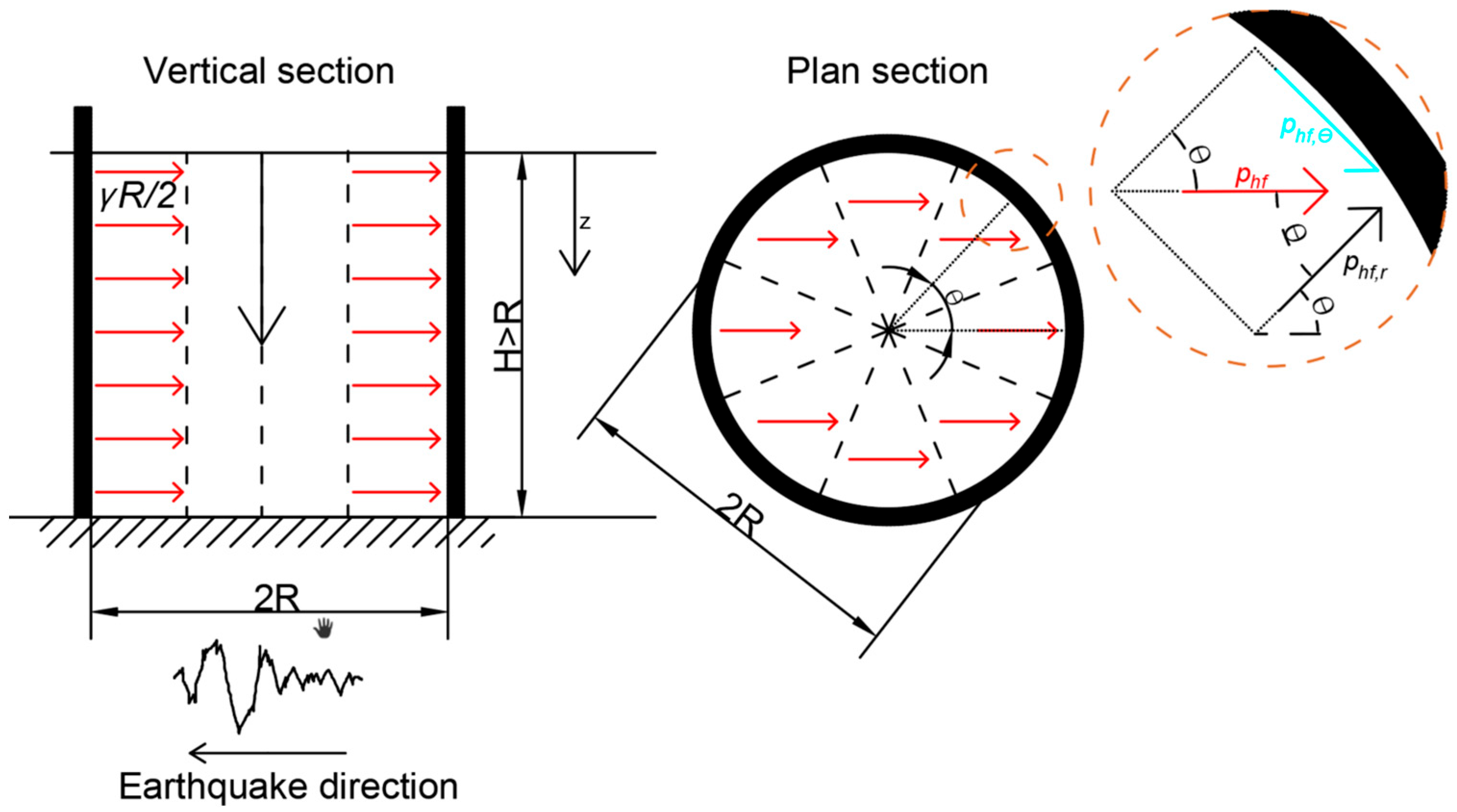
The formula is simply derived by solving a plane strain problem wherein a homogenous and isotropic elastic soil mass is contained within two rigid vertical boundaries (i.e., rigid walls) of height
H, overlying a rigid horizontal base of length
L as represented in
Figure 1, subjected to a uniform horizontal body acceleration equal to 1.0 g.
This problem led to a solution depending on the aspect ratio. The main solution was originally obtained for rectangular silos of dimensions L and H and a unit dimension into the page.
For
H/
L > 0.5 (slender rectangular silos according to Trahair’s definition),
For
H/
L < 0.5 (squat rectangular silos according to Trahair’s definition),
where
phf is the dynamic overpressure onto the silo wall due to a horizontal acceleration of 1.0 g, and
γ is the specific weight of the granular material. Equations (1) and (2) indicate full and partial mass mobilization, respectively.
Figure 2 graphically compares the difference in mobilized mass between squat and slender silos.
The solution obtained for rectangular silos was then adapted to circular silos (defined by radius R or diameter dc = 2R) on the basis of the same physical interpretation, i.e., one half of the mobilized mass in the cylindrical container is supposed to push on the “windward” side of the silo by increasing the static pressure, whilst the other half is supposed to apply a decompression force by reducing the static pressure on the “leeward” side. It can be demonstrated that this observation leads to the following formulae for the dynamic overpressure.
For
H/
dc > 0.5 (slender circular silos according to Trahair’s definition),
For
H/
dc < 0.5 (squat circular silos according to Trahair’s definition),
By considering the case of circular silos, the predefined reference dynamic overpressure in the rectangular silo case is to be subdivided into two components (radial
phf,r and circumferential
phf,θ) depending on the angle
θ, as shown in
Figure 3. The two components are evaluated as
where
θ is the angle formed between the direction of the horizontal component of the seismic input and the radial line connecting the silo section center with the silo wall at the circumferential point of interest.
If the horizontal acceleration input is different from 1.0 g and variable over the height of the silo, the dynamic overpressure proposed by Trahair becomes
where
α(
z) is the ratio between the acceleration at depth
z from the equivalent surface of the stored content and the gravity acceleration (hereafter simply referred to as the “acceleration factor”).
It is worth mentioning that Trahair’s original formula for circular silos can be derived from alternative models (i.e., Silvestri et al., 2012 [
25], which accounts for the system’s mechanical properties, such as friction coefficients and pressure ratio), as the maximum pure dynamic overpressure that can be triggered by a unit slice under seismic excitation.
3. An Inconsistency in the Current European Standard
The EN1998-4:2006 [
11] standard provides general principles and practical application rules for the earthquake design of elevated and ground-supported silos. In seismic design conditions, the additional pressure should be applied only over the part of the wall that is in contact with the stored content, i.e., up to the height corresponding to the equivalent surface of the stored content. For ground-supported circular silos, the additional normal pressure (i.e., radial component of the dynamic overpressure) can be evaluated as
, with
being the reference pressure and
θ the angle between 0 and 2
π. The reference pressure is given by
where
α(
z) is the “acceleration factor”;
H is the overall height of the granular solid from the base level up to the equivalent surface;
x =
H −
z is the height of the studied point from the silo base; and
dc is the silo diameter.
A simple comparison between the original Trahair formulae (Equations (1)–(4) and (6)) and the current Eurocode provisions (Equation (7)) is sufficient to highlight a perfect matching between the two formulations for the following cases:
but an inconsistency associated with the following cases:
Slender circular silo;
Squat circular silo.
The incongruence is concerned with the magnitude of the additional pressure, with possible important consequences on the seismic design of silos. Indeed, for the circular silo cases, the dynamic overpressure provided by EN1998-4:2006 [
11] is nearly twice the value suggested by the Trahair formula, whilst for the rectangular silo cases both references give the same prediction from an engineering point of view. The perfect agreement in the case of rectangular silos and the significant discrepancy in the case of circular silos between the two additional pressure formulations suggest that both references are based on the same assumptions and that the Eurocode formula for circular silos is most likely the result of an unintentional error—such as a miscalculation or misunderstanding—rather than a deliberate overestimation or conservative design choice.
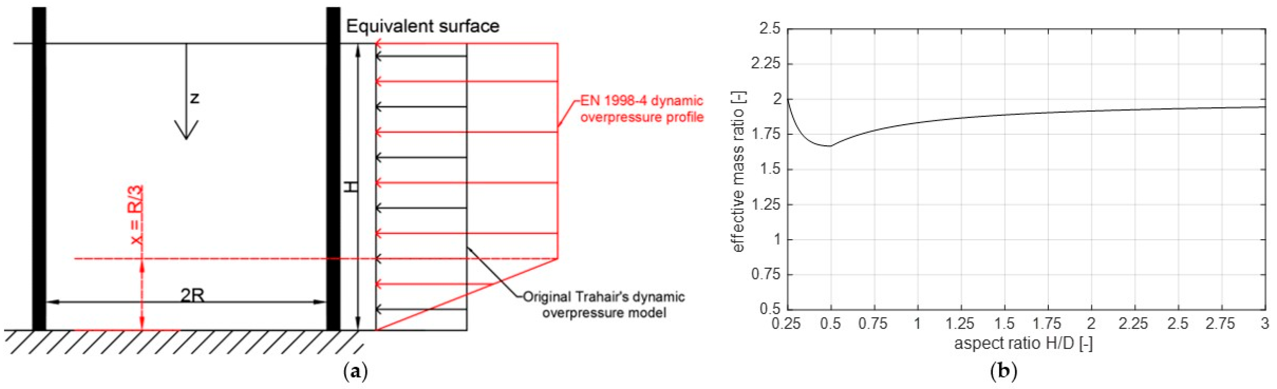
Note that there is also a slight secondary difference regarding the dynamic overpressure profile, which is however understandable and of minor importance. For actual industrial silos (i.e., aspect ratio
H/
dc ≥ 0.5), the overpressure profile has a constant value from the free granular surface down to a certain point (according to EN1998-4:2006 [
11]), defined by the
3x term that gives a height from the silo base equal to
R/3, from which the dynamic overpressure starts to linearly decrease till reaching zero at the silo base level. The overpressure reduction near the base might be correlated with the possible interaction of the lower portion of the granular solid with the base, occurring directly through the potential friction surface at ground level (
Figure 4a).
The main fundamental difference in the magnitude between the Trahair (and, consequently, the American standard) [
8,
10] and the EN1998-4:2006 [
11] predictions can be addressed by introducing the Effective Mass Ratio (
EMR). The
EMR is a ratio between two seismic forces (i.e., effective mass multiplied by design acceleration). The numerator is the EN 1998-4 seismic force, obtained by integrating the seismic additional pressures over the internal surface (i.e., the contact area between the stored material and the silo wall). The denominator is the Trahair seismic force, calculated by integrating the Trahair pressures over the same contact area.
After a few mathematical steps, and assuming that is constant over the silo height, the EMR can be expressed as a function of the filling aspect ratio H/dc, as follows.
For
H/
dc > 0.5 (slender circular silos according to Trahair’s definition),
Note that, in the case of slender silos, the denominator corresponds to the full mass (density times volume of the whole silo content) multiplied by the acceleration factor .
For 1/6 <
H/
dc < 0.5 (squat circular silos according to Trahair’s definition, which are not substantially affected by the modification introduced by EN1998-4:2006 [
11] through the 3
x term),
In the case of squat silos, instead, the denominator corresponds to a mass portion of the silo content multiplied by the acceleration factor , involving a partial volume lower than the total volume of the silo content.
To better illustrate the issue numerically, a variation in the filling aspect ratio
H/
dc was set from 0.25 to 3. It is worth noticing here that the classification of silos provided by the Eurocode is also different from the one provided by Trahair. The squat silos according to Trahair’s definition correspond to the retaining silos as defined by EN1991-4:2006 [
36]. The slender silos according to Trahair’s definition include squat, intermediate, and slender silos as defined by EN1991-4:2006 [
36].
Figure 4b clearly shows that the effective mass calculated from EN1998-4:2006 [
11] ranges roughly between 165% and 200% of the total mass, which is very conservative and physically inconsistent.
The origin of the difference between EN1998-4 and the original Trahair formula for the specific case of circular silos might be associated with one of the following events:
A potential misleading consideration of the full inertial contribution of the total mobilized mass on the “windward” side of the silo wall, as a result of a suction condition development on the “leeward” side of the wall.
A potential miscounting of the geometrical aspects, different from rectangular to circular cross-sections.
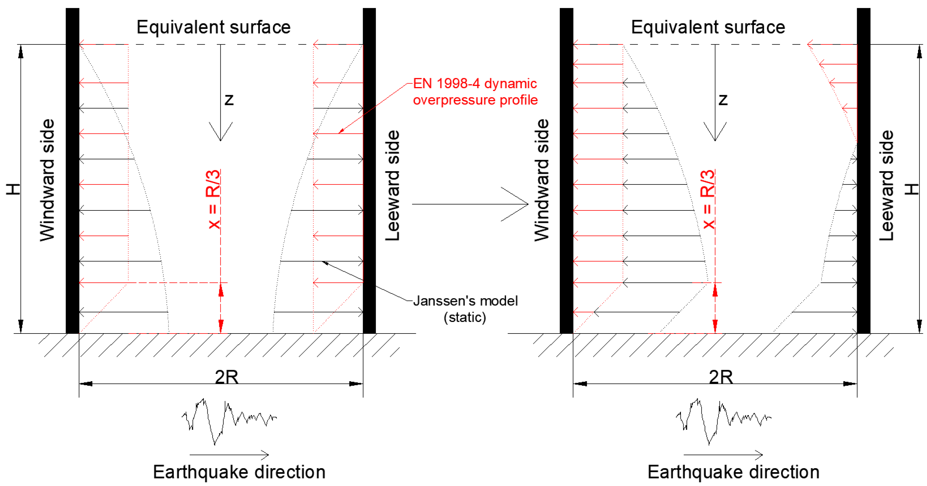
On one hand, the former possibility is associated with the condition represented by the “almost rare” case in which the seismic overpressure is larger than the static pressure, so that the earthquake effects do not translate only into an increment of the static pressure on the “windward” side of the silo and into a reduction in the static pressure on the “leeward” side, but into a physically inconsistent (corresponding to twice the total mass of the granular solid) overpressure on the “windward” side of the silo and into a full detachment of the granular solid from the “leeward” side. It is clear that the total mass of the granular solid can push on the “windward” side of the silo, but it is also clear that it cannot correspond to twice the mass (assuming that
is constant over the silo height as in
Figure 5).
On the other hand, the latter possibility is more plausible. Differently from the rectangular case for which the solution can be derived from the simplified plane strain problem (i.e., a vertical section along the input as in
Figure 2), attention should be paid towards the case of circular silos since the vertical section is not sufficient to fully address the issue, but a plan section is also necessary to account for the fan-shaped slice in the dynamic overpressure estimation. To better illustrate this issue,
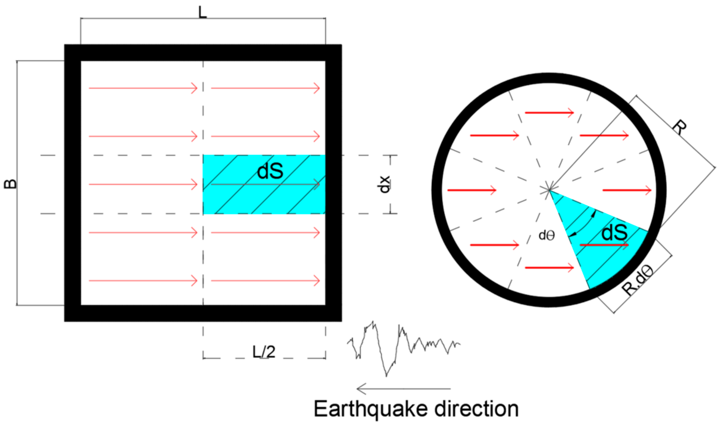
Figure 6 presents the plan view of a rectangular-shaped slice in the rectangular silo and of a fan-shaped slice in the circular silo.
Under a uniform acceleration profile and assuming, for instance, full mass mobilization (e.g., slender case), the seismic base shear
Vbase should correspond to the total volume of the stored material inside the silo. The total volume is equal to the integral of the unit slice area
dS highlighted in
Figure 6, along the plan perimeter and over the height of the silo, as reported hereafter for the rectangular and for the circular silo cases, respectively:
Consequently, the unit dynamic overpressure exerted on the wall area
dA (equal to
dxdz for rectangular silos and to
Rdθdz for circular silos) should lead to the same base shear. In this respect, Equations (12) and (13) provide the same seismic base shear as obtained starting from the correct dynamic overpressures for the rectangular and for the circular silo cases, respectively:
It is clear that
phf as written in Equation (12) is consistent with Equation (7), whilst
phf as written in Equation (13) is not. Placing the Eurocode term
dc/2 instead of
R/2 in Equation (13) would result in an amplified value as shown in Equation (8) and
Figure 4b.
Moreover, it should be noted that assuming an amplified dynamic overpressure profile would not be consistent with the rationale behind the Eurocode profile whose overpressure values tend to be reduced at the base level (through the term 3x).
4. Brief Discussion and Proposal
Different studies can be found in the literature, almost all of them numerical, where the highlighted difference (e.g., pressures predicted by the Eurocode are almost double those numerically obtained) was encountered and observed, but not sufficiently explained [
31,
32,
33,
34,
35]. It should be noted that the calibration and validation of numerical models remains a challenge, primarily due to the lack of supporting experimental data. In this respect, particular focus can be placed on two very recent studies [
34,
35]. In the more recent one [
35], the researchers calibrated a numerical model using the dynamic response of a tested silo specimen on a shaking table [
27], which was performed by the second author of this work. The study found that the average numerical values of additional pressure were significantly lower than those predicted by the Eurocode (EC), approximately half of the expected values as shown in Figure 9 of [
35]. The earlier study [
34], on the other hand, combined both experimental and numerical approaches. It found that the additional pressure values—both experimental and numerical—averaged approximately half of the Eurocode prediction in Figure 10 and Figure 14 of [
34].
In light of the previous discussions in
Section 3, the values found by previous researchers are physically consistent with the maximum feasible base shear force that can be triggered by the solid material inside the silo. This differs from the EN1998-4 formula, which yields a higher value that exceeds full mass mobilization.
Moreover, as far as this inconsistency is not addressed, the following design-oriented consequences are expected:
In the case of steel silos, the relatively high level of design additional pressures (i.e., horizontal forces in lateral and circumferential components) would lead to a general overdesign of the silo wall sheets (i.e., thicker walls) over the silo height, and specifically in the upper part where the rationale of the EN1991-4:2006 [
11] standard aims at reducing the forces in static conditions by accounting for Reimberts’ modification [
37] on Janssen’s model for the squat silo category (as per the Eurocode definition).
Overdesign of the stiffener cross-sections in steel silos (i.e., larger sections), as the earthquake-induced vertical axial forces would be nearly twice as large as those predicted by Trahair’s model.
Higher thickness of the reinforced concrete shell wall of concrete silos over the silo height.
Higher overall weight of concrete silos, resulting in slightly higher static vertical and seismic inertial forces in the design phases of the silo foundation. Such an issue is neglected in steel silos as their wall thicknesses are lower, and therefore, their weights are negligible with respect to the filling material weight.
The previous points clearly indicate that a physically consistent revision of the Eurocode formula might lead to economic savings in different countries classified as moderate-to-high-seismic areas (e.g., Italy, Greece, Portugal, Romania, and other EU and Extra-EU countries where EN1998-4 is applicable or commonly used).
Finally, current analytical studies and experimental works have recently shown that full mass mobilization is imprecise and even conservative for a broad category of industrial silos with a filling aspect ratio lower than 2, especially when characterized by a flat-wall section [
25,
27]. A similar trend is observed for corrugated-wall silos, albeit to a lesser extent. However, given the lack of sufficient available experimental results, it is prudent to retain the Eurocode assumptions. Nonetheless, the current formula should be modified to align more closely with the one suggested by Trahair as follows:
Equations (14) and (15) represent a physically based correction of the Eurocode formulae. If the Eurocode were to remain conservative, then it might consciously include a model safety factor (up to a certain desired value) for both circular and rectangular cases.
5. Concluding Remarks
This paper aims at achieving an in-depth interpretation and an improved understanding of the design-oriented formulae of the additional pressure explicitly prescribed by the EN1998-4:2006 European code and implicitly referenced by the American standard, for the seismic design of silo walls.
A critical pursuit of the historical development of the problem formulation is presented, aiming to uncover conceptual and methodological inconsistencies that may have been overlooked in the evolution of current standards.
A conceptual incongruence is highlighted regarding the dynamic overpressure in the case of circular silos: the current formula provided by EN1998-4 corresponds to an extremely high effective mass, up to twice the value of the full mass of the silo content (depending on the filling aspect ratio of the silo), which seems to be physically unjustified. This issue has also been encountered, but not explained, in several recent works by other researchers. In this short paper, a methodological explanation of this incongruence is provided, starting from the early dynamic pressure models and offering a comprehensive discussion of several related aspects. Moreover, a qualitative and quantitative evaluation of this incongruence is presented, and two possible scenarios explaining its origin are discussed. Finally, a proposal for a physically based correction is suggested, retaining the current assumptions made by EN1998-4.
Finally, the impact of the highlighted incongruence has been addressed through a list of the possible consequences in the design and manufacturing processes for both steel and reinforced concrete silos accounting for their technical differences.


