Abstract
Deploying an airbag when a vehicle occupant is too close to it can cause injury. An adaptive Airbag Control Unit (ACU) would improve the effectiveness of the safety system, provided it is aware of the actual position of the occupants once the crash is going to occur. Occupants can be monitored with vision-based and radar-based sensing in the vehicle, but the research question is whether other reliable devices exist. In this research, a real seat is equipped with four sensors in the supports from the floor, as well as an Inertial Measurement Unit (IMU) and a microcontroller. The device is capable of identifying correct position or different Out of Position (OP) conditions and inform an adaptive ACU. The paper presents the seat layout in detail and its testing in extensive driving experiments with multiple participants. Depending on the position of the driver, the identification is correct 45–100% of the time. Monitoring the occupant position by a sensorized seat is feasible and can improve the reliability of the onboard safety system when integrated with other occupant monitoring devices.
1. Introduction
Airbag deployment may cause further injury to an occupant if he or she is Out of Position (OP) [1,2,3,4,5,6]. To mitigate this risk, car manufacturers must pass rigorous tests for the airbag deployment against OP manikins [7,8,9]. Modern vehicles are already equipped with an Airbag Control Unit (ACU) that adapts to the speed of the vehicle, severity of the crash, or seat belt use [10,11], but the ACU might be improved if it was supported by an occupants monitoring system, making it adaptive to their position as well [12,13,14,15].
Computer vision-based systems are powerful devices for monitoring the attention and drowsiness of the driver by eye and face tracking in research [16,17,18] and have even been equipped in commercial vehicles [19,20,21,22]. Recent studies have shown technologies that can monitor the position of the occupants in the vehicle. However, current vision-based occupant monitoring systems may result in false positives in cases of occlusions and other factors such as bad lighting, occupants with body dimensions at the extreme percentiles, or in OPs very far from the correct ones; this might often be the case in SAE levels 4 and 5 [23]. These vision-based systems also raise legitimate concerns about data privacy [24].
A sensorized seat is another type of device with occupant monitoring capabilities. Evaluations over a prolonged time can assess the comfort of the occupant [25,26]. Pressure sensors in the seat can inform the vehicle of presence and weight, using this information to control the restraint system [27,28]. The seat pressure can even be processed with machine learning techniques for identifying the driver patterns and enhancing the driving experience [29,30]. With data from the seat, privacy is no longer an issue, as the data is minimized and anonymous. In previous research, the authors described a method for identifying the position of an occupant through a set of Force Sensing Resistors (FSR) and an Inertial Measurement Unit (IMU) embedded in the seat [31,32]. A modular vehicle seat monitoring different significant regions greatly improved the monitoring reliability through the use of load cells [33,34].
The weight of the occupant on board can be detected through four sensors placed on the seat supports [35]. The signals can be used to identify the occupant, i.e., adult or child, to inform the safety systems of the vehicle. Weight can also be detected using only two sensors, monitoring two of the four supports, to measure the inclination of the vehicle or to detect a collision [36,37]. The load cells and components for occupant identification must be carefully assembled [38] and maintained [39,40] to ensure device reliability. Strain gauges mounted in the four seat supports can be used to determine the load variations [41] or to detect the weight and size of the occupant [42]. The weight and position of the occupant, detected by four seat supports very similar to Type-S load cells, can be used to inform an adaptive ACU [43]. However, these supports are too bulky for implementation in a commercial vehicle and are too influenced by loads not aligned to the vertical axis. None of the patents described integrate information on driving dynamics via IMU. However, in real driving, the load on the seat is predominantly affected by the acceleration of the vehicle. These patents seem more suitable for an adaptive configuration of the vehicle’s passive safety, rather than a more active safety that involves continuous monitoring of the driving scenario.
The present research describes a simplified and improved seat using only four load cells to monitor the occupant position. The paper is organized as follows. Section 2 presents the sensorized seat device and its signal processing. The results of real driving tests are reported and discussed in Section 3, while the concluding remarks are shown in Section 4.
2. Sensorized Seat for Occupant Monitoring
The device is developed with the aim of integrating the sensors into a seat as close as possible to a homologable one without compromising safety, ergonomics, or comfort. Sensors must be accurate and fast reading. The positioning of sensors must ensure reliable monitoring of passengers with any body percentile. The design solution is to modify the frame of an existing car seat without modifying its overall structure. With this solution, functionality and comfort are not compromised as long as there is a solid structure for housing the sensors. For this research, the seat of a 2016 Peugeot 308 SW is used. The four seat supports are cut and a load cell is inserted into each one. The position of the Center of Gravity (CG) of the seat-occupant system is calculated by averaging the four signals. The equipment is also equipped with an IMU in order to compensate for the vehicle accelerations when evaluating the CG shifts.
2.1. Dimensioning of Load Cells
To select the sensors, the forces acting on the four supports are approximately calculated below. The seat is measured experimentally with digital scales considering an intermediate backrest inclination of 21°, although different settings would obviously shift the load distribution on the supports [44]. Note that the reference system is with the x-axis in the travel direction, the y-axis in the transverse direction, and the z-axis in the vertical direction [45]. The distance between the supports in the travel direction is = 253 mm. The mass of the seat is approximately = 13.50 kg, distributed as = 11.95 kg on the rear supports and = 1.55 kg on the front supports. With being the gravity acceleration, the vertical total force results for the seat, distributed on each of the two rear supports and on each of the front ones, as shown in Figure 1a. Balancing the moments with respect to the rear supports, the coordinate of the CG of the seat is:
while the vertical coordinate of the CG of the seat is evaluated, as shown in Figure 1b, as:
where the angle 9° is determined experimentally by rotating the seat backward until the load on the front supports is cancelled out and, therefore, the CG is vertical on the rear supports.
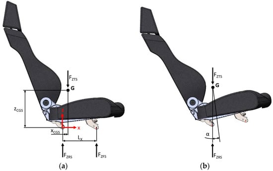
Figure 1.
Car seat with forces on supports when measuring (a) the longitudinal x and (b) the vertical z coordinates of the CG.
The occupant is much more difficult to measure than the seat. In fact, the ends of the legs rest on the floor and their weight does not pass through the seat supports, while the hands and part of the arms can be considered to be resting on the steering wheel. Furthermore, weight distribution is different from occupant to occupant. Finally, the procedure followed for the seat involves considering the occupant as a rigid body when it is not, leading to errors that are not easily predictable. Therefore, an approach based on literature data on a dynamic model of the seat-occupant system was followed but adapted to the seat used in the present research [44]. The adapted model considers springs with infinite stiffness. First, an occupant with a body similar to the model, i.e., including clothing and accessories, is weighed. The occupant is tall. The test occupant sitting on the seat weighs on the rear supports and on the front supports, which corresponds to a mass distribution of 59% on the rear supports and 41% on the front ones. Note that the weight of 7 kg on the floor is not considered in the following calculations. The multi-body model is therefore adapted as shown in Figure 2, maintaining the same distribution of masses in longitudinal x and vertical z directions. In the model, is the mass measured for the seat, while to are the concentrated masses that describe the body of the sample occupant, as reported in Table 1. The CG of the bodies in the plane is also reported.
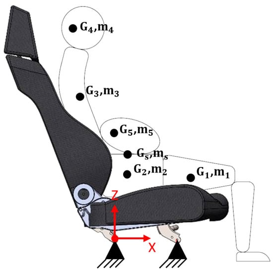
Figure 2.
Multi-body model of the seat-occupant system.

Table 1.
Seat and occupant parameters in the multi-body model.
The overall seat-occupant system has a total mass of . By averaging the coordinates of the CGs, weighted with respect to their masses, the total CG at position is calculated. It is assumed that the occupant does not detach from the seat in all the dynamic conditions considered, so the overall seat-occupant system is attached to the supports as a single body. In stationary conditions, the supports must withstand a total vertical force of , distributed on each of the two rear supports and on each of the front supports.
Considering an acceleration in the travel direction, the balance of the moments with respect to the rear supports is:
where is the vertical force acting on each of the front supports. Considering a very high maximum acceleration , like that of a racing car, a traction force (results from (3)) is applied to each of the front supports and, consequently, the force on the two rear supports is increased to . Considering an emergency braking as , the loads on the front and rear supports are, respectively, calculated from (3) as and .
The balance of the moments in a transverse direction due to centripetal accelerations in turning results in loads of the same order of magnitude as the ones already calculated, but a little lower thanks to a greater y distance between the supports. Calculations are omitted for sake of brevity.
The most serious case is that of a frontal impact, where an acceleration can be assumed as representative of a frontal crash [46]. The loads on the rear and front supports then becomes and , respectively, from (3). In this case, the horizontal force acting on the supports is calculated as .
Acceleration in driving conditions is considered for dimensioning the load cells, which must read both in compression and in traction. Note that the load cells must be reading up to an instant before the accident to inform the vehicle safety systems. The case of impact is considered to evaluate the ultimate resistance of the sensors for the structural safety of the device. Considering the seat-occupant system as a single body is a conservative assumption because there will certainly be other contacts from the occupant, i.e., with the steering wheel, with the door, with the vehicle floor, and with the pedals. In the event of an impact, the load of the occupant will also be transferred to a significant extent onto the airbags and seat belts, which are in turn fixed to the chassis. Ultimately, the hypothesis of a rigid seat-occupant system can be considered favorable to safety with regards to the dimensioning of the supports.
2.2. Layout of the Sensorized Seat
Four DYZ-101–500 kg load cells [47] are mounted in the seat supports, as shown in Figure 3. The load cells hold the supports in the vertical direction, leaving the adjustments of longitudinal and vertical positions of the seat free. DYZ-101 is a pancake-type load cell with small height. It is capable of sensing both compression and traction and compensates the off-axis forces well. This DYZ-101 monitors a nominal load in a range up to 500 kg, with 0.05% nonlinearity and 0.03% hysteresis, 10 kHz the high response frequency, and 0.03% the effect of temperature on output. The safe overload is 150% of the nominal load, with a maximum overload of 200%. These specifications make the DYZ-101 suitable for reading the load while driving in all conditions. However, under very strong assumptions for the calculation, the specified overload does not guarantee safety in event of an accident. Complete safety requirements are left for future studies, as no crash tests are expected to be conducted in this research. Figure 4 shows the wiring of all the electronics, including the four DYZ-101–500 kg load cells with dedicated signal amplifiers, the Arduino UNO microcontroller, and a serial connection with a laptop for monitoring using Microsoft Excel Macro-Enabled Worksheet in Office 16 through the PLX-DAQ application. The device is completed with a BNO055 IMU for monitoring the accelerations of the vehicle.

Figure 3.
Assembly layout of the DYZ-101 load cells under the seat supports: (a) complete layout, (b) exploded view, and (c) assembled support.
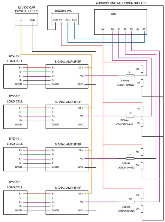
Figure 4.
Scheme of electronics wiring of the sensorized seat.
A dynamometer is used to apply both compressive and tractive loads in both axial z and transverse directions. Impulsive loads 0–100 N and progressive loads in the same range are considered. The tests demonstrate the reliability of measures, with a resolution of ±1 kg. Due to frequency response, the sensor dynamic is satisfactory. The DYZ-101 does not read when off-axis loaded.
2.3. Calibration and Signal Processing
The signals are calibrated in the setup cycle and then processed in the loop cycle of the software, as reported below. The calibration routine should be performed at the beginning of each driving session. It therefore compensates for the different body percentiles of the occupants and the different configuration of the backrest or pan angles. The position of the CG in the plane [45] is calculated as the average of the signals from the four load cells weighted with respect to their position, as shown in Figure 5. The calibration setup must be run with the occupant in a normal position to calculate the shift factors for the CG and the scale factors for the accelerations. The shift factors for CG have a negative sign as they are used in the reading loop to shift the CG to the position on average. The xshift factor depends on the body size and the position adjustment of the seat, while yshift is very slightly affected by the asymmetrical positioning of the occupant. The accelerations and are already monitored centered on . The scale factors for accelerations are used to amplify the signals up to the magnitudes of the CG positions to make them comparable. In particular, the scaling factors have a negative sign since accelerations and inertia forces naturally have opposite signs.
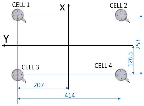
Figure 5.
Distances of the four supports for weighing the signals when calculating the position of the CG in travel x and transverse y directions.
- setup cycle
- //calculate xshift factor as average of x coordinate of CG
- //calculate yshift factor as average of y coordinate of CG
- //xscale factor is the ratio between the average magnitude of the shifted CGx and the average magnitude of the accx
- //yscale factor is the ratio between the average magnitude of the shifted CGy and the average magnitude of the accy
- loop cycle
- //shift the CG to (0, 0) position on average
- //scale the accelerations to match the CG coordinates
The four monitored and adjusted values, , , , and , are then processed in the same loop cycle with the occupant monitoring routine reported below in order to identify the position as: 0 normal, 1 forward-reclined, 2 left-reclined, and 3 right-reclined:
- occupant monitoring
- if and then position = 0
- if and then position = 2
- if and then position = 3
- if and then position = 1
The tolerance for reading is set at in this study during preliminary tests to fine tune the algorithm. This tolerance can be refined in future studies by using machine learning techniques.
3. Driving Tests
The present section reports the real driving tests with the sensorized seat on a 2016 Peugeot 308 SW car. The experiments are carried out by three drivers, with anthropometries reported in Table 2, who must drive a prescribed track. The first experiments are carried out by the second driver. The experiments consist of the following sequence of maneuvers, as shown in Figure 6:

Table 2.
Anthropometries of the three test drivers.
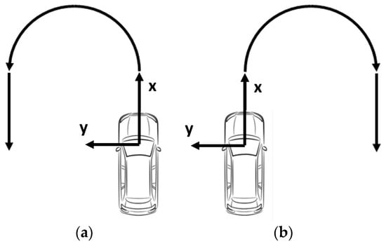
Figure 6.
Test track with (a) left or (b) curve.
- start from stop position;
- straight-line acceleration and straight-line path for approximately 15 m;
- 180° left (or right) turn of approximately 7.5 m radius;
- straight-line path and braking to stop in approximately 15 m.
The total duration of each test is approximately 16 s. The monitored CG and acceleration in the (a) and (b) tests in the normal position are shown in Figure 7, the ones in forward-reclined OP are shown in Figure 8, while Figure 9 and Figure 10 show the tests with the left- and right-reclined OPs, respectively. and follow the left scale in mm units. and follows the same but scaled units. The position identification follows the right scale with the encoded position numbers.
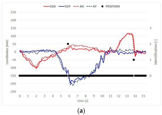
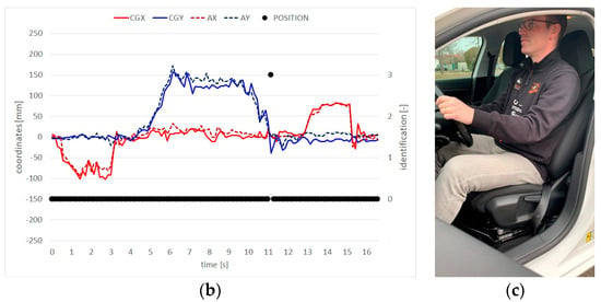
Figure 7.
CG and position identification in (a) left and (b) right curve tests in (c) normal driving position.
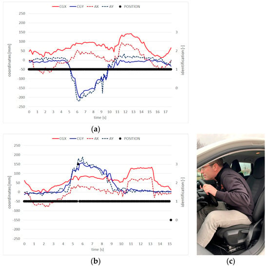
Figure 8.
CG and position identification in (a) left and (b) right curve tests in (c) forward-reclined OP.
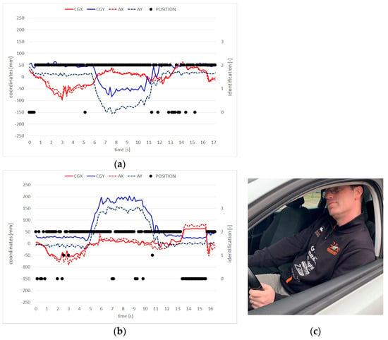
Figure 9.
CG and position identification in (a) left and (b) right curve tests in (c) left-reclined OP.
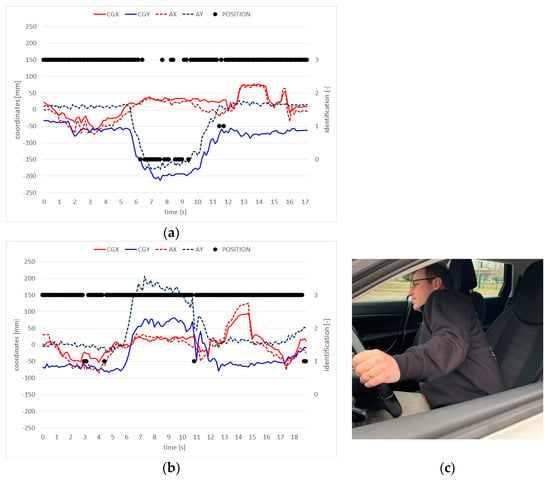
Figure 10.
CG and position identification in (a) left and (b) right curve tests in (c) right-reclined OP.
In the experiments, serial communication between the Arduino and the laptop with PLX-DAQ is the bottleneck for the cycle time, achieving only a 7.3 Hz sampling speed. Tests that avoided serial communication in the loop but downloaded the data after experiment finished achieved a 40–50 Hz sampling speed. The identification is correct 98% of the time for Figure 7a and 99% for Figure 7b, 100% for Figure 8a and 98% for Figure 8b, 88% for Figure 9a and 77% for Figure 9b, and 84% for Figure 10a and 95% for Figure 10b. Incorrect identification is caused by peaks of acceleration due to road irregularities, changes of the driver position aimed at balancing the transverse accelerations of the car, or by loading on other parts of the car than the seat, such as the steering wheel, floor, or door.
Extensive experiments are then carried out by the three drivers, who have to drive a prescribed track. Since it is not possible to reproduce a real driving scenario, as the device is not approved for driving on public roads, we replicate maneuvers that have been identified as critical for pre-crash and crash conditions [48]. The track is created on the runway of the Aero Club of Modena [49], Italy, as shown in Figure 11. The indicated dimensions consist of the exact length of the painted stripes in the center of the runway and the distance between them. Driving the track one direction (blue) and back (green) consists of the following sequence:

Figure 11.
Test track as created on the runway of the Aero Club of Modena.
- start moving in 1st gear;
- half-eight turn at approximately 15 km/h speed;
- maximum acceleration in 2nd gear until speed limit activation at 50 km/h;
- left lane change;
- right lane change;
- hard brake to stop;
- start moving in 1st gear again;
- half-eight turn at approximately 15 km/h speed;
- maximum acceleration in 2nd gear until speed limit activation at 50 km/h;
- right lane change;
- left lane change;
- hard brake to stop.
First, each driver is asked to adjust the seat into a comfortable position and familiarize themselves with the car during a short driving session. Then, each driver has to complete three laps, taking each position already described: normal position, forward-, and left- and right-reclined OPs. For each driver, the first lap in the normal position is used to calibrate the device, as described in Section 2.3. Each lap takes approximately 50–55 s, with slight variations due to an initial delay before the 1. start after the go signal maneuver, a different pause after the 6. first braking maneuver, and a delay in the acquisition end after the 12. final stop maneuver. In the experiment, 36 laps are completed.
The second lap of the tests in normal position for all three drivers is shown in Figure 12. The second lap of the tests in the forward-reclined OP is shown in Figure 13. In Figure 12, the sequence of the twelve maneuvers of the lap is further highlighted, as it can be clearly identified from the CG movements and the car accelerations in longitudinal directions (red lines) or in transverse directions (blue lines).
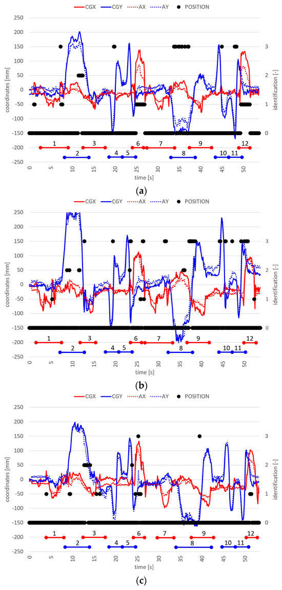
Figure 12.
Second test of three, in normal position for (a) 1st, (b) 2nd, and (c) 3rd drivers.
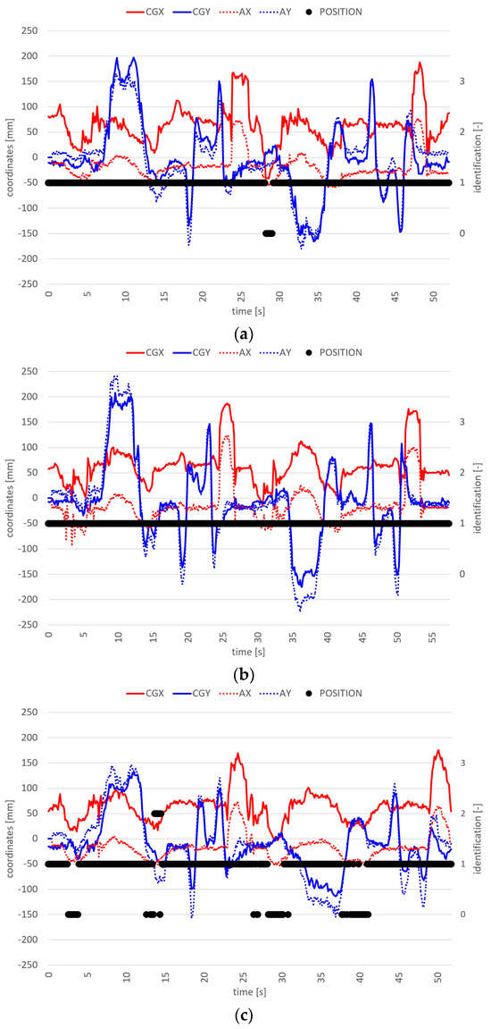
Figure 13.
Second test of three, in forward-reclined OP for (a) 1st, (b) 2nd, and (c) 3rd drivers.
The shifts of the CG of the seat-occupant system in the longitudinal direction in these first experiments for the three drivers are summarized in Table 3. The second column reports the raw CG x position in the normal position with respect to the seat reference frame, as shown in Figure 2. The real positions of the CG confirm that it is very close to the rear supports, as calculated in Section 2.1 for the theoretical model [44] with the parameters of Table 2. The third column reports the calculated xshifts factors, as described in Section 2.3, to calibrate the origin in direction by moving the CG to the geometric center between the load cells, as shown in Figure 5. Even though the body percentiles of the drivers are different, these xshift factors are comparable. The fourth and fifth columns show the CG errors and their standard deviations for driving laps in normal position. Considering the harsh maneuvers, the errors can be considered rather small when compared to the xshift factors. The sixth and seventh columns show the positions and their standard deviations for the driving laps in forward-reclined OP. The shift relative to the calibrated origin of the seat is clearly identifiable. Note that the CG of the seat-occupant system is the weighted average of GS and G1 through G5 as described in Section 2.1 and, since GS, G1, and G2 do not move in this OP and G5 moves only slightly, the shifts of G3 and even more of G4 are much greater, bringing the head of the drivers much closer to the steering wheel.

Table 3.
CG shifts of the seat-occupant system for calibration and signal processing in normal and forward-reclined OP.
Figure 14 and Figure 15 show the tests in the left- and right-reclined OPs, respectively. A summary of the position identification is also provided in Table 4, averaging, for each driver, the second and third laps in the normal position and all three laps for each OP.
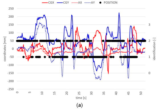
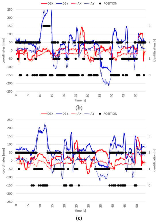
Figure 14.
Second test of three, in left-reclined OP for (a) 1st, (b) 2nd, and (c) 3rd drivers.
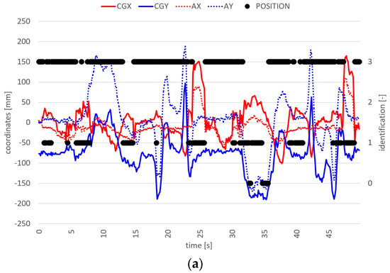
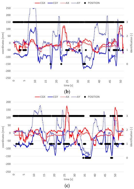
Figure 15.
Second test of three, in right-reclined OP for (a) 1st, (b) 2nd, and (c) 3rd drivers.

Table 4.
Identification of positions in the experiments for the three drivers.
In these extensive experiments, the normal position is correctly identified almost 90% of the time. This is clearly not a good result, as it would deactivate the normal safety features of the car if it were used. On the other hand, incorrect identification is due to very harsh maneuvers. The driver, in fact, must support himself by acting on the steering wheel with his hands and on the lower cockpit with his knees. Furthermore, the strong pressure on the brake and clutch pedals during braking must be considered. All these actions influence the CG shifting, significantly distorting the position identification.
The forward-reclined OP is identified very well by the controller. The right-reclined OP is identified almost 75% of the time. One possible reason for this poor identification might be the need to keep eyes on the track in those difficult maneuvers for safety reasons. As a result, the OPs were taken correctly by the drivers, but not to the extreme. Left-reclined OP is even more difficult to identify, achieving only 50% correct results. The left-reclined OP is certainly the most constrained, as the driver can only slightly recline the body against the door.
Figure 16 shows the plots of the CG position in the plane for the tests in normal position (black dots), forward-(red), left-(green), and right-reclined (blue) OPs for all three drivers. The average CGs are the big points with large borders, while the small points represent the samples in the experiments. The CG positions are reduced by the scaled accelerations of the vehicle, so they represent the movements of the driver relative to the moving platform. Except for the deviations due to harsh maneuvers, the positions can be identified by the CG position in the plane, which is the vertical projection of the CG position.
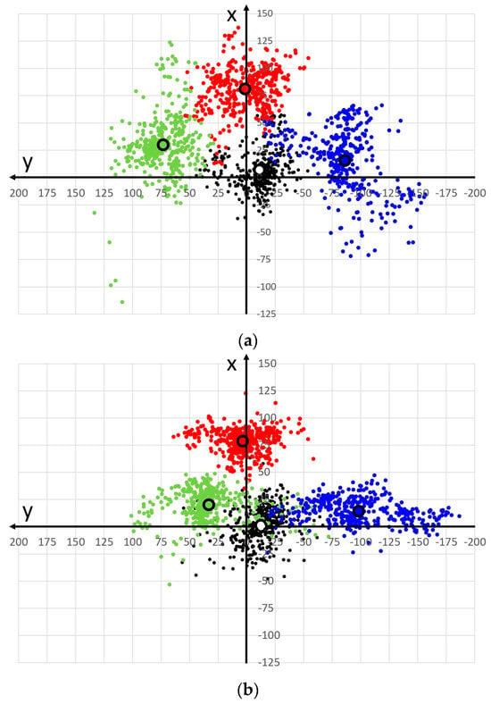
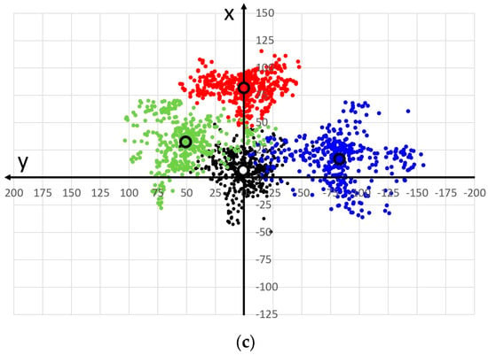
Figure 16.
CG positions reduced by the scaled accelerations for the second test of three, in normal position (black), forward-(red), and left-(green) and right-reclined (blue) OPs, for (a) 1st, (b) 2nd, and (c) 3rd drivers.
4. Conclusions
This paper presents a vehicle seat for continuous monitoring of the position of an occupant through load cells integrated into the four lower supports. The cells are sized to withstand loads while driving and the assembly layout ensures they only read in vertical direction. The adjustments of longitudinal and vertical positions of the seat are left free, allowing tests to be carried out without any influence on the driving comfort. To function in all safety critical conditions, a crash event is also considered in the design of the device, using literature data and simplifications. Under extreme assumptions, the load cells appear not to be compliant with safety requirements. Future works will quantify loads during a crash with greater reliability, test the ultimate strength of the load cells, and possibly design safety restraining structures. Another design option could be to not use commercial load cells but to include strain gauges into appropriately shaped supports, making them sensitive to the deformations caused by load from the driver.
The load cells are much more precise than the polymer FSRs we have used in previous work [31,32]. Compared to FSRs, they are also precise, linear, and fast reading, without hysteresis; therefore, they provide very reliable data. Compared to the other prototype using load cells in a modular seat [33,34], this latest device is much simpler, as it reduces the number of sensors from 52 to just 4. With some data processing, which can be improved in future works with machine learning techniques, the seat we present in this article still provides reliable results. On the other hand, the feasibility of the system is much higher, since the design solutions already optimized in commercial seats and related production processes can be completely reused. The layout with four load cells enables continuous monitoring of occupants by averaging the load signals in the microcontroller to continuously calculate the CG of the seat-occupant system. Using the CG to represent the average position of a human body has already been studied in biomechanics to calculate balance, stability, performances, energy expenditure, gait abnormalities, rehabilitation progress, and injury risk [50,51]. However, it may not capture the full complexity of the movement of individual body segments and interaction with the environment, which is the car cockpit in the present research. Indeed, this simplification sometimes leads to a misinterpretation of the driver’s position. Nevertheless, a novelty in this research is the study of the CG in the car considered as a mobile platform. Considering the driving dynamics via IMU is a new and fundamental feature, since in real driving the load on the seat is predominantly affected by the accelerations of the vehicle.
Calibration and signal processing enable the CG of the seat-occupant system to be compared with the car accelerations, as detected by the IMU, in longitudinal and transverse directions. The presented algorithm for classification is therefore able to understand whether the shifts in the CG are due to the inertia forces while driving or to changes in the occupant position.
Three drivers performed extensive experiments, replicating maneuvers that have been identified as critical for pre-crash and crash conditions in previous research. The tests only investigate the driver monitoring, but it can be assumed that occupant monitoring would be similar, if not simpler, since no interactions with the steering wheel influences the results. In most cases, the correct position or the OP conditions are correctly identified. However, a percentage of incorrect identification is caused by road noise in the experiments and, inevitably, by the driver loading other parts of the car other than the seat. Therefore, the proposed device is certainly not suitable for safety purposes alone, since it does not achieve correct identification in 100% of cases, and so requires further development. On the other hand, the present research demonstrates the feasibility of the sensorized seat, even if it needs to be integrated with other sensors in the car cockpit to monitor all interactions within the structures and devices.
The seat also measures the weight of the occupant; therefore, it would allow adaptive restraining and airbag strategies depending on the types of anthropometry with little effort. Future works will improve the conditioning of the signals from the load cells, the use of machine learning techniques in the software, and integrate the seat device into the overall safety system of the car, including vision-based occupant monitoring and adaptive restraint systems.
Author Contributions
Conceptualization, methodology, experiments, data curation, writing original draft and editing, A.V.; equipment design, construction, software, experiments and writing review, C.G.; supervision and writing review, F.L. All authors have read and agreed to the published version of the manuscript.
Funding
This research received no external funding.
Data Availability Statement
The raw data supporting the conclusions of this article will be made available by the authors on request.
Acknowledgments
The authors are very grateful for the support provided by the Aero Club of Modena, Italy, and for giving us the privilege of using the runway for the experiments.
Conflicts of Interest
The authors declare no conflicts of interest.
References
- Lebarbé, M.; Potier, P.; Baudrit, P.; Petit, P.; Trosseille, X.; Vallancien, G. Thoracic Injury Investigation Using PMHS in Frontal Airbag Out-of-Position Situations; SAE Technical Paper; SAE: Warrendale, PA, USA, 2005. [Google Scholar] [CrossRef]
- Maxeiner, H.; Hahn, M. Airbag-Induced Lethal Cervical Trauma. J. Trauma Acute Care Surg. 1997, 42, 1148–1151. [Google Scholar] [CrossRef]
- Potula, S.R.; Solanki, K.N.; Oglesby, D.L.; Tschopp, M.A.; Bhatia, M.A. Investigating occupant safety through simulating the interaction between side curtain airbag deployment and an out-of-position occupant. Accid. Anal. Prev. 2009, 49, 392–403. [Google Scholar] [CrossRef]
- Prasad, A.K.; Samaha, R.R.; Louden, A.E. Evaluation of Injury Risk from Side Impact Air Bags; SAE Technical Paper; 2001-06-0091; SAE: Warrendale, PA, USA, 2001; pp. 1–12. [Google Scholar]
- Ryan, S. An Innovative Approach to Adaptive Airbag Modules; SAE Technical Paper; SAE: Warrendale, PA, USA, 1998; p. 980646. [Google Scholar] [CrossRef]
- Yoganandan, M.; Pintar, F.A.; Zhang, J.; Gennarelli, T.A. Lateral impact injuries with side airbag deployments—A descriptive study. Accid. Anal. Prev. 2007, 39, 22–27. [Google Scholar] [CrossRef]
- 571.208 Standard No. 208; Occupant Crash Protection. Federal Motor Vehicle Safety Standards (FMVSS), Code of Federal Regulations; Updated 5 December 2023. Available online: https://www.ecfr.gov/on/2023-12-05/title-49/section-571.208 (accessed on 6 May 2024).
- 571.214 Standard No. 214; Side Impact Protection. Federal Motor Vehicle Safety Standards (FMVSS), Code of Federal Regulations. Updated 5 December 2023. Available online: https://www.ecfr.gov/on/2023-12-05/title-49/section-571.214 (accessed on 6 May 2024).
- Viano, D.C. History of airbag safety benefits and risks. Traffic Inj. Prev. 2024, 25, 268–287. [Google Scholar] [CrossRef] [PubMed]
- Mutlag, A.H.; Mahdi, S.Q.; Salim, O.N.M. A Comparative Study of an Artificial Intelligence-Based Vehicle Airbag Controller. In Proceedings of the 2022 IEEE 18th International Colloquium on Signal Processing & Applications, Selangor, Malaysia, 12 May 2022. [Google Scholar] [CrossRef]
- Machens, K.U.; Kübler, L. Dynamic Testing with Pre-Crash Activation to Design Adaptive Safety Systems. In Proceedings of the 27th International Technical Conference on the Enhanced Safety of Vehicles (ESV), Yokohama, Japan, 3–6 April 2023; Available online: https://www-esv.nhtsa.dot.gov/Proceedings/27/27ESV-000067.pdf (accessed on 6 May 2024).
- Depottey, T.A.; Schneider, D.W. Airbag Cushion with Adaptive Venting for Reduced Out-of-Position Effects. U.S. Patent No. 7,261,319, 28 August 2007. [Google Scholar]
- Farmer, M.E.; Jain, A.K. Occupant classification system for automotive airbag suppression. In Proceedings of the IEEE Computer Society Conference on Computer Vision and Pattern Recognition, Madison, WI, USA, 18–20 June 2003. [Google Scholar] [CrossRef]
- Hall, I.; Rao, M.K.; Ryan, S. Airbag System for Out-of-Position Occupant Protection and Adaptive Venting. U.S. Patent No. 7,448,646, 11 November 2008. [Google Scholar]
- Schneider, D.W.; Rose, L.D. Airbag Adaptive Venting for Out-of-Position Occupants. U.S. Patent No. 7,770,926, 10 August 2010. [Google Scholar]
- Bergasa, L.M.; Nuevo, J.; Sotelo, M.A.; Barea, R.; Lopez, M.E. Real-time system for monitoring driver vigilance. IEEE Trans. Intell. Transp. Syst. 2006, 7, 63–77. [Google Scholar] [CrossRef]
- Borghi, G.; Venturelli, M.; Vezzani, R.; Cucchiara, R. Poseidon: Face-from-depth for driver pose estimation. In Proceedings of the IEEE Conference on Computer Vision and Pattern Recognition, Honolulu, HI, USA, 21–26 July 2017. [Google Scholar] [CrossRef]
- Dong, Y.; Hu, Z.; Uchimura, K.; Murayama, N. Driver Inattention Monitoring System for Intelligent Vehicles: A Review. IEEE Trans. Intell. Transp. Syst. 2011, 12, 596–614. [Google Scholar] [CrossRef]
- Driver Attention Monitor (Honda Sensing® Feature). Available online: https://www.hondainfocenter.com/2024/CR-V/Feature-Guide/Interior-Features/Driver-Attention-Monitor/ (accessed on 8 March 2024).
- A Moment More Attention: Mercedes-Benz Presents “Awake”. Available online: https://media.mercedes-benz.com/article/2798d797-85c0-45bc-aa01-e12fcbc5745f (accessed on 8 March 2024).
- Mazda Driver Attention Alert. Available online: https://www.mazda.com/en/archives/safety2/active_safety/daa/ (accessed on 8 March 2024).
- Volvo Driver Alert. Available online: https://www.volvocars.com/en-eg/support/car/xc60/article/f57bafffba0c0468c0a8015174f226d8 (accessed on 8 March 2024).
- SAE On-Road Automated Vehicle Standards Committee. Taxonomy and Definitions for Terms Related to On-Road Motor Vehicle Automated Driving Systems. SAE Stand. J. 2014, 3016, 1–16. Available online: https://www.sae.org/standards/content/j3016_201401/ (accessed on 6 May 2024).
- Kong, Q.; Lu, R.; Yin, F.; Cui, S. Blockchain-based privacy-preserving driver monitoring for MaaS in the vehicular IoT. IEEE Trans. Veh. Technol. 2021, 70, 3788–3799. [Google Scholar] [CrossRef]
- Kyung, G.; Nussbaum, M.A. Driver Sitting Comfort and Discomfort (part II): Relationships with and Prediction from Interface Pressure. Int. J. Ind. Ergon. 2008, 38, 526–538. [Google Scholar] [CrossRef]
- Na, S.; Lim, S.; Choi, H.S.; Chung, M.K. Evaluation of driver’s discomfort and postural change using dynamic body pressure distribution. Int. J. Ind. Ergon. 2005, 35, 1085–1096. [Google Scholar] [CrossRef]
- Schousek, T.J. Vehicle Occupant Restraint with Seat Pressure Sensor. U.S. Patent No. 5,474,327, 12 December 1995. [Google Scholar]
- White, C.W.; Behr, L.W. Passenger Out-of-Position Sensor. U.S. Patent No. 5,071,160, 10 December 1991. [Google Scholar]
- Martínez, M.V.; Del Campo, I.; Echanobe, J.; Basterretxea, K. Driving behavior signals and machine learning: A personalized driver assistance system. In Proceedings of the IEEE 18th International Conference on Intelligent Transportation Systems, Las Palmas de Gran Canaria, Spain, 15–18 September 2015. [Google Scholar]
- Zhang, Y.; Lin, W.C.; Chin, Y.K.S. A pattern-recognition approach for driving skill characterization. IEEE Trans. Intell. Transp. Syst. 2010, 11, 905–916. [Google Scholar] [CrossRef]
- Vergnano, A.; Leali, F. Out of Position Driver Monitoring from Seat Pressure in Dynamic Maneuvers. In Proceedings of the 2nd International Conference on Intelligent Human Systems Integration, San Diego, California, USA, 7–10 February 2019. [Google Scholar] [CrossRef]
- Vergnano, A.; Leali, F. A methodology for out of position occupant identification from pressure sensors embedded in a vehicle seat. Hum. Intell. Syst. Integr. 2020, 2, 35–44. [Google Scholar] [CrossRef]
- Vergnano, A.; Piras, A.; Leali, F. Vehicle Seat with Occupant Detection System. IT Patent No. 102019000022221, 26 November 2019. [Google Scholar]
- Vergnano, A.; Piras, A.; Leali, F. Modular Car Seat for Monitoring the Pressure Distribution on Regions of Pan and Backrest. In Proceedings of the 3rd International Conference on Human Systems Engineering and Design, Pula, Croatia, 22–24 September 2020. [Google Scholar] [CrossRef]
- Toshiaki Ishida, T.; Ogasawara, H. Load Detection Structure for Vehicle Seat. JP Patent No. JP3904913B2, 7 November 2001. [Google Scholar]
- Ito, K.; Inayoshi, M.; Enomoto, A.; Fujii, H. Vehicle Tilt Detecting Apparatus and Seat Load Detecting Apparatus Using the Same. U.S. Patent No. US8296099B2, 23 October 2009. [Google Scholar]
- Inayoshi, M.; Enomoto, A.; Fujii, H. Apparatus and Method for Determining Impact on Vehicle and Apparatus for Warning Impact on Vehicle. U.S. Patent No. US8328276B2, 11 December 2009. [Google Scholar]
- Endo, S.; Sato, K.; Nishide, H.; Yamazaki, T.; Kumakiri, N.; Kojima, M.; Yoshifuku, M.; Furukawa, T. Passenger’s Weight Measurement Device for Vehicle Seat and Attachment Structure for Load Sensor. U.S. Patent No. US7823951B2, 22 October 2008. [Google Scholar]
- Endo, S.; Sato, K. Vehicle Seat with Load Sensor. Patent No. US9835479B2, 5 December 2017. [Google Scholar]
- Endo, S.; Sato, K. Vehicle Seat Including Load Sensors between Wall Portions. U.S. Patent No. US8822850B2, 2 September 2004. [Google Scholar]
- Hamada, M.; Sekizuka, M.; Fukawatase, O.; Fujimoto, O. Sitting Passenger Detecting Apparatus and Sitting Passenger Detecting Method. U.S. Patent No. US6356200B1, 12 March 2000. [Google Scholar]
- Yanagi, E. Load Sensor and Seat Weight Measuring Apparatus with a Plurality of Strain Gauges. U.S. Patent No. US7055365B2, 6 June 2002. [Google Scholar]
- Osmer, W.; Wills, M.; Blakesley, P. Vehicle Occupant Position Detector and Airbag Control System. U.S. Patent No. EP1202876B1, 28 May 1999. [Google Scholar]
- Kumbhar, P.; Xu, P.; Yang, J. Evaluation of Human Body Response for Different Vehicle Seats Using a Multibody Biodynamic Model; SAE Technical Paper 2013; 2013-01-0994; SAE: Warrendale, PA, USA, 2013. [Google Scholar]
- European New Car Assessment Programme (Euro Ncap) Test Protocol—AEB VRU Systems, Version 3.0.3. Available online: https://cdn.euroncap.com/media/58226/euro-ncap-aeb-vru-test-protocol-v303.pdf (accessed on 22 April 2024).
- Agaram, V.; Xu, L.; Wu, J.; Kostyniuk, G.; Nusholtz, G. Comparison of Frontal Crashes in Terms of Average Acceleration; SAE Technical Paper; 2000-01-0880; SAE: Warrendale, PA, USA, 2000. [Google Scholar]
- DYLoadCell Datasheet. Available online: http://www.dyloadcell.com/product/clcgq/82.html (accessed on 8 March 2024).
- Reed, M.P.; Ebert, S.M.; Jones, M.H.; Park, B.K.D. Occupant Dynamics during Crash Avoidance Maneuvers (No. DOT HS 812 997); United States Department of Transportation. National Highway Traffic Safety Administration: U.S., 2021. Available online: https://rosap.ntl.bts.gov/view/dot/54737 (accessed on 6 May 2024).
- Aero Club of Modena. Available online: https://aeroclubmodena.it/ (accessed on 23 April 2024).
- Caron, O.; Faure, B.; Brenière, Y. Estimating the centre of gravity of the body on the basis of the centre of pressure in standing posture. J. Biomech. 1997, 30, 1169–1171. [Google Scholar] [CrossRef] [PubMed]
- Munoz, F.; Rougier, P.R. Estimation of centre of gravity movements in sitting posture: Application to trunk backward tilt. J. Biomech. 2011, 44, 1771–1775. [Google Scholar] [CrossRef] [PubMed]
Disclaimer/Publisher’s Note: The statements, opinions and data contained in all publications are solely those of the individual author(s) and contributor(s) and not of MDPI and/or the editor(s). MDPI and/or the editor(s) disclaim responsibility for any injury to people or property resulting from any ideas, methods, instructions or products referred to in the content. |
© 2024 by the authors. Licensee MDPI, Basel, Switzerland. This article is an open access article distributed under the terms and conditions of the Creative Commons Attribution (CC BY) license (https://creativecommons.org/licenses/by/4.0/).