1. Introduction
Nowadays, customers have a growing desire for more individual and up-to-date products [
1,
2,
3]. Therefore, products are characterized by an ever-shorter product life cycle. The simultaneous fulfillment of constantly growing standards puts product development under enormous time and cost pressure. On the one hand, concepts in the form of prototypes have the potential to accelerate the generation of new products by identifying problems early on in their development [
4] (pp. 2–3). On the other hand, cost- and time-intensive processes in conventional prototyping limit this potential. To overcome those barriers, the development of new design methods that accelerate the creation of prototypes are needed [
5] (p. 280).
Additive manufacturing is one of the most promising processes for achieving this goal. Due to its fundamentally different nature, additive manufacturing enables new designing approaches extended to what conventional processes allow for [
6] (pp. 10–12).
In the current state of the art, the small build volume of additive machines limits the application of additive manufacturing [
7]. To overcome this limitation without increasing the size and thus the cost of the machines, the joining of multiple smaller parts is proposed. This contrasts with the general opinion that joints are weak points in a design and worth the effort to be avoided [
8] (p. 2). Furthermore, avoiding a multi-part structure to reduce assembly costs is one of the basic rules in injection molding [
9]. These general opinions rooted in conventional processing encourage the development of complex individual parts and reduce the pursuit of innovative joining processes. Therefore, only a small number of new publications about the joining of plastics can be found.
For additive manufacturing, however, these statements are no longer valid. Additive parts are manufactured layer-by-layer in a single step, regardless of their complexity. The resulting design freedom creates a broad scope for new joining processes. To combine design freedom with an economic use of joining, a uniform method that is as universal as possible is required.
Such a design method was developed for the production of large-area and thin-walled interior trim parts for the “UNICARagil” project [
10]. The focus is on parts made from plastics, and therefore it is geared toward additive processes suitable for those materials. The method offers the opportunity to break through the tendency of avoiding joints and to set a new trend. This new design method and its application are presented in this paper. Before introducing the development process leading to this method, a summary of the current state of the art regarding prototyping is given to disclose the current research gap. Thereafter, the state of the art regarding joining in additive manufacturing is given, which forms the basis for the approach to solve the research gap.
2. Prototyping
An interactive, continuous development process using prototypes is proven to achieve a functional and valid product concept [
11] (pp. 9–10). In modern design methodologies, like design thinking [
12], prototyping is an integral element. To sustain the use of prototypes, their production should be as economical as possible. Costs are distributed over a single or small number of prototypes, which is why individual and expensive machines, tools, or expensive processes are avoided. The remaining selection of processes, especially to produce complex parts, is highly limited. Instead of conventional methods with multiple processing steps, “rapid prototyping” is used more frequently nowadays.
Rapid prototyping describes the use of additive or generative manufacturing processes to produce prototype components. These processes aim to reproduce the characteristics of a product as quickly and accurately as possible [
11] (p. 9). Additive manufacturing applies material layer-by-layer to create a part. The individual additive processes differ in their operating principles for material deposition. They can also be differentiated by the materials used. While the additive manufacturing of metals is becoming increasingly popular, the high machine and production cost conflicts with the demands for the prototyping of large parts. Therefore, this paper focuses on additive processes for plastic parts. Fused deposition modeling (FDM) is one of the most affordable and widespread additive processes [
13] and serves as the basis for the investigations carried out in this paper. In FDM, a plastic filament is continuously fed into a heated nozzle, melted, and applied in thin layers, one on top of each another [
9]. This leads to a quick production of complex prototype parts, but the achievable part size is limited by the build volume of the additive machine. With the need for parts larger than the available build volume, the direct use of rapid technologies ends.
This necessitates the use of conventional processes. Within the scope of financial possibilities in prototyping, costly processes and machines are substituted by high manual effort with lower quality. A representative method to produce large, thin-walled parts is the designing of molds and subsequent molding of the parts. The most widely used process for manufacturing composite components is hand lay-up and is considered the comparative process for the investigations in this thesis. Along with fiber spraying, hand lay-ups account for a quarter of the total fiber-reinforced plastics production and cover the manufacturing of large-area parts with low unit quantities as in prototyping [
14] (pp. 35–36).
Comparing hand lay-up to rapid prototyping shows the shortcomings when the prototyping of large parts is required. Parts that fit the build volume of additive machines benefit from manufacturing in a single step and a process that offers ever greater advantages over conventional processes as part complexity increases [
6] (pp. 9–12). In contrast, parts larger than the build volume of additive machines that use hand lay-up require multiple processing steps for manufacturing the molds and the hand lay-up itself. Molds for complex parts require cost-intensive machining, while in hand lay-up, an attempt is made to compensate for further machining costs by using labor-intensive manual processes with lower quality.
4. Approach
The development of the method follows a systematic process based on the guideline VDI 2221 [
15]. First, the objective is precisely defined, and the requirements that the method needs to fulfill are derived by discussing the boundary conditions. Afterward, the function structure of the method is set. From there, a solution space for the sub-functions of joining is generated, and a joint concept is derived. Next, a segmentation concept is presented. The combination of both sub-concepts follows in
Section 5 in the form of the overall design.
To render the method more useful to potential users, a detailed description of the design choices and an insight into their reasoning is given.
4.1. Aim
The design method aims to produce large-area, thin-walled parts out of plastic by using additive manufacturing. In these terms, any part that exceeds the build volume of the machine is considered large area. Parts with an average material thickness in the millimeter range are considered thin walled in the scope of the design method. Parts belonging in this category are, among others, the body, housing, and trim parts of large products, such as large machinery or vehicles of every kind. One example is the production of an interior trim part in
Section 6.4. The FDM process is used as one of the most widespread and cost-effective additive processes [
13,
18]. Nonetheless, the developed method satisfies the general requirements of additive processing.
The aim is to enable an assembly of segments that possesses the characteristics of a solid part while offering an economic advantage over the current state of the art in prototyping.
The problem statement, a solution-neutral description of the aim in the form of a concise sentence and an unbiased perspective, is as follows:
Segment a large-scale, thin-walled part and assemble the segments to form this part.
Regarding the first part of the purpose, it is explicitly stated that the developed method can react to a given shape rather than requiring a specific design for its application.
4.2. Requirements
For the integrity of the method, knowledge of all requirements implied by the problem statement is essential. Therefore, the boundary conditions and challenges concerning design, manufacturing and joining are investigated, and all necessary requirements are derived.
In general, the method aims to be as universally applicable as possible and, therefore, proceeds from an arbitrary shape of this part. With respect to the scope of this paper, the method aims to preserve this shape, especially the thinness of the part.
In the UNICARagil project, the method is applied to the production of automotive interior trim parts. These components have a visible side, whose shape needs to be unchanged, as well as a rear side, which ensures the stability and mounting of the part and can be altered.
4.2.1. Segmentation
The challenges of segmentation are related to those of a puzzle game, except that it poses a three-dimensional instead of a two-dimensional problem. This increases the complexity and relativizes questions regarding the uniform design and assembly of three-dimensional segments.
In contrast to a puzzle, the three-dimensional space offers no distinct joining direction. Accordingly, our method has to specify a universal procedure for dividing the part into individual segments. The feasibility and limits of this universal procedure are a key challenge and were investigated in the concept generation (
Section 4.6).
Further requirements arise away from a holistic view of the part toward a consideration of an individual segment. The joint design at their edge, connecting them to one another, needs to adapt to the individual shape and orientation of the segment in its specific area of the part.
The final assembly needs to be self-contained and without any open degrees of freedom to resemble a solid part. Therefore, the joining geometry needs to position the segments in relation to each other. The aim is not to limit the application of the method by the means used for segmentation and geometric features of the joint.
4.2.2. Manufacturing and Joining
The segments need to be suitable for additive manufacturing out of plastic. Apart from the major size limitation, several other weaknesses of additive manufacturing, in this case, FDM printing, exist and threaten the success of the method.
General challenges in FDM printing are overhangs, warpage, and tolerances (
Figure 2). Their occurrence leads to geometric deviations on each segment. The joining geometry needs to not only maintain the fitment of the segments despite these deviations, but also compensate for the resulting tolerances for an overall conform assembly. This includes the compensation of a curvature of the joining edge because of warpage. For detailed information on the challenges of additive manufacturing, please refer to the technical literature [
6,
20].
The main requirement of the joint itself is to allow force transmission between segments on the level of the solid material of the part.
4.2.3. Time and Costs Consumption
Finally, the time required for the application of the method must be considered. The fulfillment of all imposed requirements can lead to sufficient but complex solutions. With growing complexity, the time required for the application of the method increases.
The method cannot disproportionately surpass the time required for conventional manufacturing processes. In addition, the method must be able to adhere to the schedule of a real-world application. Otherwise, the advantage of lower material and equipment costs would be lost to the cost of labor-intensive processing, and the method would not find any real application, regardless of its technical potential. The time for the application of the method consists of the design time as well as the production and assembly time. Since the manufacturing time for the segments is roughly constant regardless of the geometric design due to additive manufacturing, the time for designing the segments needs to be kept to a minimum.
4.2.4. Requirement List
The requirements derived from the analysis of the framework conditions were documented in the form of a requirements list (
Table 1). The requirements list serves the generation of the solution space as well as the final evaluation of the concept. The requirements were numbered and divided into demands (F) or wishes (W). The method must fulfill the demands, while wishes are optional to increase the performance. In addition, a requirement was characterized with a characteristic according to Pahl and Beitz [
21]. They define which product feature or which area in the product life cycle the requirement addresses.
4.3. Function Structure
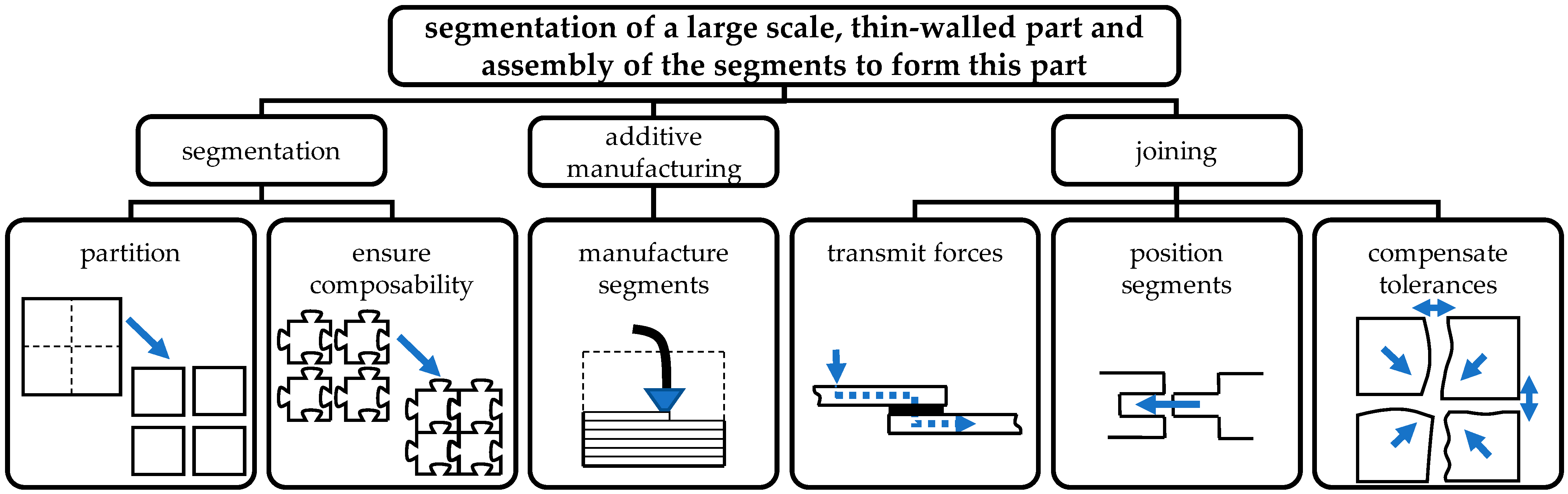
The functions that are needed to fulfill the requirements were divided into three subsystems (
Figure 3): the segmentation of the part geometry, the additive manufacturing of the segments, and the joining of the segments to the final assembly.
Segmentation summarizes the aspects of dividing the part into individual segments in a defined manner and enabling the assembly of the segments by avoiding collisions through the geometric design.
Additive manufacturing produces the individual segments. It is to be considered passive in relation to the method because the process is predetermined but dictates several requirements as well as possibilities for the method (
Section 4.2.2).
The joining of the segments has the primary function of force transmission to ensure part integrity. Due to the joining in an undefined three-dimensional space, the secondary function of positioning the segments to one another follows. To meet the challenges of additive manufacturing, the joint must compensate for any tolerance of individual segments (
Section 4.4.3).
The presented sub-functions are not in a specific sequence but stand for themselves and generate interdisciplinary dependencies on each other. The method of joining has a major influence on the possibilities of segmentation and assembly. Furthermore, all design measures must be compliant with additive manufacturing. These and other challenges are examined in the following. Conformity with all sub-functions considered at every stage of development is crucial.
4.4. Solution Space for Joining of Segments
Due to the interdisciplinary dependencies between the sub-problems, the choice of the joining method influences the possibilities of segmentation and vice versa.
There are unlimited possibilities for the segmentation of a part in the three-dimensional space while the design of the joint is constrained by set requirements. An additional restriction due to the premature choice of segmentation could render joining impossible. For this reason, the solution space for the design of the joint is investigated prior to the segmentation. Afterward, a segmentation principle compliant with the chosen joint design is derived.
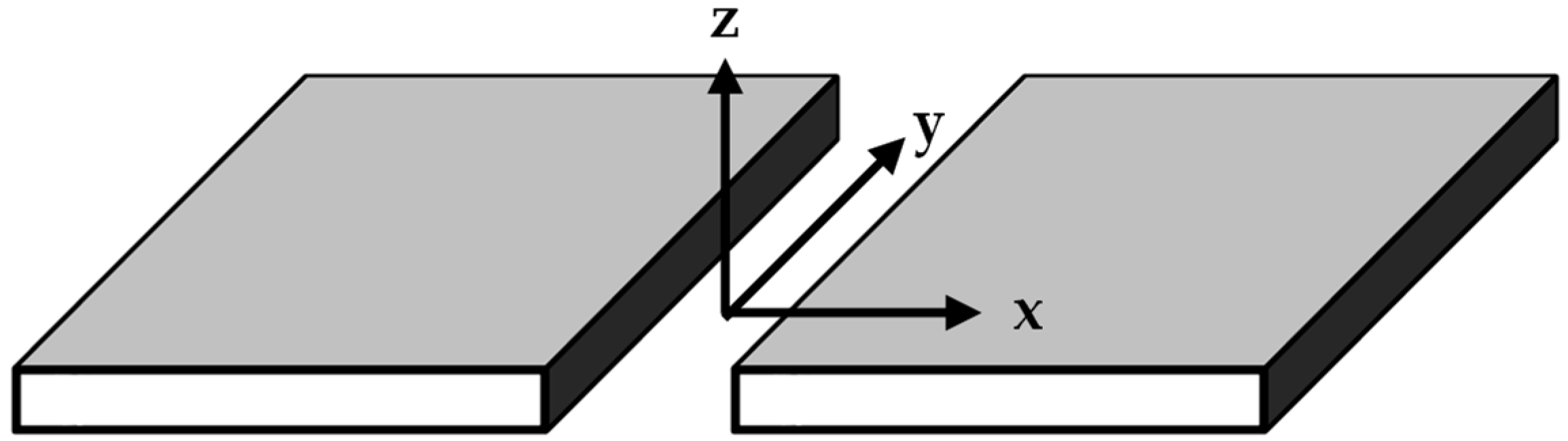
To make the problem tangible, the representation of the segments is simplified. Segments, which theoretically can have any three-dimensional shape, are reduced to a flat and rectangular form with a uniform thickness (
Figure 4). This simplifies the conception and allows for the visualization of solution ideas. Nevertheless, the solution is developed under the premise that an application to an arbitrary shape of the segments is possible.
For a better description of the joint, the spatial directions relative to the joint are defined (
Figure 4). With respect to the joining of the two segments, the X-direction is perpendicular to the cut edge and tangential to the top surface of the part. The Z-direction and Y-direction are located in the cut plane. While the Z-direction is perpendicular to the part’s top surface, the Y-direction is tangential to the cut edge.
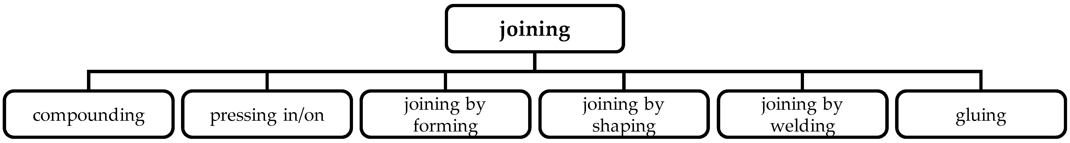
The joining of the segments must fulfill the three functions of force transmission, positioning, and tolerance compensation. To find a suitable joint design for this purpose, the groups of joining techniques for plastics (
Figure 1) were analyzed with respect to each function in view of the set requirements.
Welding and riveting processes were excluded by their process nature. Due to complex shapes, the required tools could be prevented access to the joint, and the overall processing quality and reliability do not meet the requirements.
4.4.1. Force Transmission
All types of joints based solely on connecting elements, such as screws and pins, cannot ensure uniform joining of the segments due to relative movement because of forces acting between each connection point. Relative movement is inconsistent with an assembly that resembles a solid part. In addition, connecting elements lead to excessive stress at the connection point [
8] (pp. 131–133). Stress concentration interferes with uniform transmission and strength on the level of a solid part.
Adhesive bonds are advantageous in this respect, as they enable a material bond across the entire contact area. If the bond is created along the entire cut edge between two segments, no relative movement of the segments or uniform force transmission is possible.
4.4.2. Positioning
Due to the poor surface quality of the FDM process, no adequate positioning can be achieved solely by the geometry of the joint and the direct contact of the joining surfaces to each other. The extent to which post-processing is necessary and possible during the prototyping process must be considered for an overall concept.
Gap-filling adhesives can compensate for poor surface quality, warpage, and irregularities in the surface of the segments. A problem in the application of an adhesive joint is the fixture of two segments in a precise position to one another until cured.
Screwing cannot provide precise positioning due to play in the through hole.
Press fitting is the only joining technique that precisely positions two segments to one another.
4.4.3. Tolerance Compensation
Tolerance compensation aims to compensate for process-related dimensional deviations in the length and width of individual segments and, thus, for the influence of these on the overall assembly. These deviations include the warpage of segments, which leads to a curvature of the cut edge in the X/Y-plane, and the tolerance in the length and width of segments. Therefore, the joint geometry must offer adjustability of the segment position in the X-direction relative to each other. This allows the gap between the segments to be adjusted to the required overall dimensions of the part.
For adjusting the gap between two segments, a freedom of movement in the X-direction while fixing all other degrees of freedom is necessary. Only press fitting can fulfill this condition. When using, for example, dowel pins oriented in the X-direction, two segments are precisely positioned in the Y- and Z-directions to one another. By control of the distance in the X-direction between the segments during pressing, the gap can be freely adjusted to counteract dimensional deviations.
4.4.4. Joint Design Implementation
In addition to fulfilling the three main functions of the joint, the designing effort determines the suitability of joining techniques since it is decisive for the time required for the method. Therefore, the joining techniques were evaluated by carrying out simple design tests.
In the case of screwing, this test shows that a bolted joint is complex in its design and requires individual adaptation to the segment geometry, while a press-fit connection with dowel pins is less complex to implement because neither a thread nor a contact surface for the screw head is required.
In contrast to screwing and press fitting, an adhesive joint and a purely interlocking joint do not require any predefined holes for joining. The geometry of the joining surfaces can be freely designed within the framework of the specified requirements. This allows for a joining geometry adaptive to any shape of the joining edge of a segment. A partially universal design of the joint is mandatory to fulfill the time requirement for the design.
4.4.5. Preliminary Conclusion
The use of screws is not suitable for joining the segments. Bolted joints conflict with a large number of requirements and the time and effort required for their implementation precludes their economic use.
An adhesive joint in combination with an adequate joint geometry is a joining method that fulfills the uniform transmission of forces across the entire joint surface between two segments as well as the structural implementation in an economical timeframe. Without compliance with this requirement, a joining method would not be effective. Accordingly, adhesive joining was chosen to fulfill the force transmission and implementation requirements. However, it cannot fulfill the secondary function of positioning the segments and is not sufficient for tolerance compensation.
Press fitting, on the other hand, offers particularly good properties with respect to positioning and tolerance compensation. However, press fitting is viable only to a certain extent because of time consumption in design.
In conclusion, none of the joining methods on their own satisfies all requirements. While the screwing, welding and riveting processes can be excluded, the geometric fitting, press fitting and adhesive joining techniques fulfill necessary requirements but are not sufficient on their own (
Table 2).
4.5. Hybrid Joint Design
The hybrid joint design combines the advantages of the three joining methods: geometric fitting, press fitting and adhesive joining. While adhesive joining satisfies the requirements for force transmission over the entirety of the contact area, press fitting allows for precise positioning and tolerance compensation. Finally, the geometric fit defines the interaction of both principles.
The tolerance compensation determines the orientation of dowel pins in terms of press fitting. The axis of the pins needs to be perpendicular to the X-axis. For precise positioning, at least two dowel pins are required to join two segments. Then, the segments have a single degree of freedom in the X-direction to each other and therefore accomplish tolerance compensation.
The last step to a holistic joining concept is a geometric fit that allows for adhesion and subsequent force transmission while being compliant with press fitting and tolerance compensation. To achieve a high joint strength, stress other than compression and shear are avoided regarding the adhesive joint. In order to achieve similar performance to a solid part, an overlapping adhesive joint is used [
22] (pp. 587–588). This allows for an enlarged bonding area to be utilized, compared to the cut surface.
Additionally, the dowel pins transmit the largest part of critical gap stresses in relation to the adhesive joint, due to their orientation.
For the geometry of an overlap, a number of common designs exist [
23] (p. 187). An overlap suitable for joining the segments must meet the requirements of the method.
Maintaining the top surface of the overall part prohibits a simple overlap. Furthermore, to enable additive manufacturing, the joint must provide a support surface to rest on the print bed of the FDM printer. Therefore, scarf joints are not usable.
Additionally, the aim of a universal application conflicts with the use of a tongue-and-groove joint. This conflict limits the assembly by requiring the plugging of the segments in the X-direction. A tongue-and-groove joint requires a directional progression of the geometry over the length of the plug-in connection. This is inconsistent with an adaptive design of the joining geometry according to the part’s overall shape.
Due to the indeterminate shape of the cut edge of the segments, geometries that require further joining elements, such as a separate strap, are avoided. Additional joining elements are not economical in design or production.
The last requirement placed on the geometric fit is production without support structures. Of the remaining possible geometries according to Messler and Savage [
24] (p. 187), the joggle lap is the only geometry able to fulfill this requirement, while being the geometrically simplest and, thus, the least design-intensive solution. It consists of a rabbet with a shoulder and a tongue (
Figure 5). Support-free production is therefore only possible for an orientation where the tongue rests on the print bed of the FDM printer due to the overhanging shoulder of the rabbet (
Figure 5). If each segment has at least one side with a tongue, the joggle lap joint is sufficient for the method.
In summary, examination of the joining methods shows that a hybrid joint using a combination of a press-fitting and adhesive joining with a joggle lap meets the requirements. In accordance with the new requirements resulting from this preselection, the segmentation options are examined.
4.6. Segmentation Concept
Segmentation is the last main function of the method requiring a solution principle. As the first step in the application of the method, it determines the shape and number of segments and has a decisive influence on the time required and the complexity of segment creation. To meet time requirements, the segmentation procedure must be partially automated. Therefore, segmentation is simplified to reduce design work for the geometric elaboration of each segment.
The first decision to be made is the basic shape into which the individual segments are cut. Crucial to print quality is the orientation of the part for manufacturing. It determines the surface quality and whether support structures must be used. For the best possible utilization of the printing space and the greatest possible independence from the specific shape of a segment, a positioning of the segments on one of their sides resulting from cutting it out of the overall part was presupposed. This means that one of the cut surfaces of a segment rests on the print bed of the machine. For the widespread cubic build volume of additive machines, a rectangular shape is the simplest geometric representation of a segment allowing it to be oriented on its side.
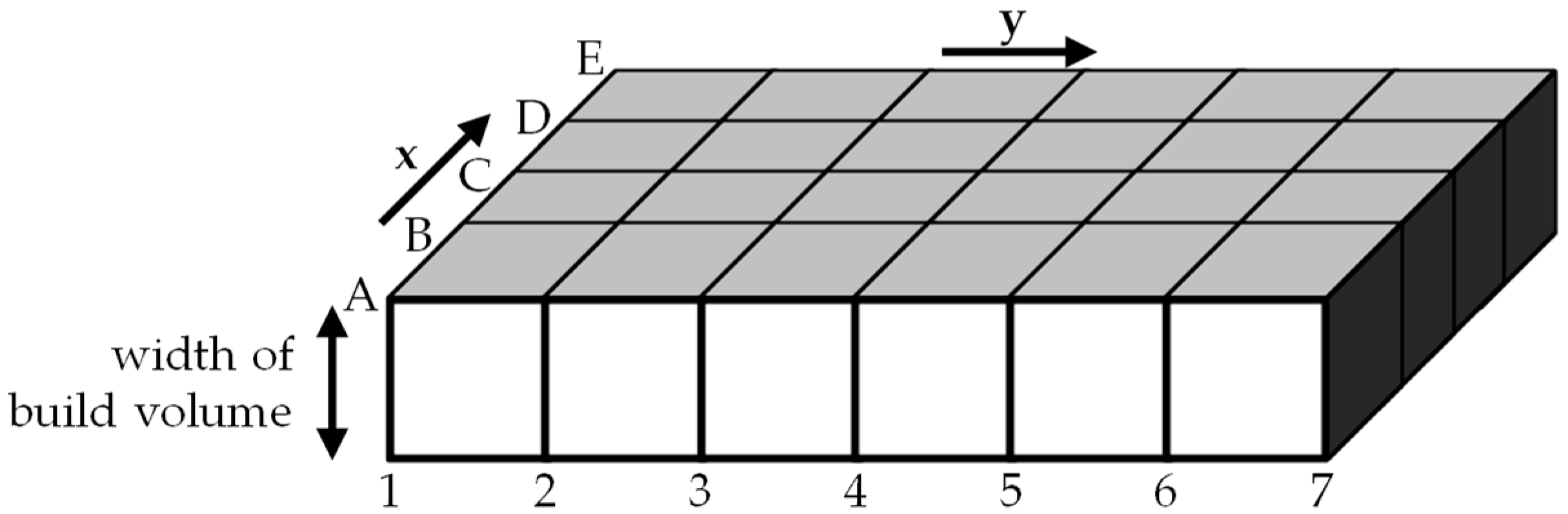
For the unambiguous definition of the cut section, the definition of the cutting direction is necessary. The more segments of the part that can be cut in the same cutting direction, the lower the design effort. This applies in general to all large-area, thin-walled parts that can be accommodated in a cubic volume with a height equaling the width of the build volume of the additive machine. For the FDM printer in terms of this paper, the height equals 200 mm.
For parts exceeding this volume, segmentation in a uniform cutting direction can no longer be guaranteed and must be checked individually. If this is not possible, a second volume with the same height must be defined for the part of the body outside the first volume. This is oriented ideally in a way that the body fits completely in those volumes. For the cutting plane between both volumes, the joint of the segments must be created individually. The developed method can be used in the respective volumes (
Figure 6).
The considerations of this paper were limited to parts that fit into one defined volume. The simplest way to cut a part is with the help of uniform cut planes parallel to the Z/X- or Z/Y-plane. The cut planes parallel to the Z/Y-plane were named with numbers in ascending order, while the cut planes parallel to the Z/X-plane were named with letters in the order of the alphabet (
Figure 6). After the part is cut, each segment is in a cube bounded by the four adjacent cut planes and the top and bottom of the defined volume and, therefore, does not exceed the available build volume.
After the partitioning of the segments has taken place, the individual segments are equipped with the hybrid joint geometry. For overlapping, each rabbet is inserted into the matching tongue of its counterpart. Due to its rectangular shape, a segment has four sides for joining with adjacent segments. The arrangement of the rabbet and tongue to those sides is crucial for successful assembly. For overhang-free printing, a segment can rest with the tongue but not with the rabbet on the print bed. Consequently, each segment must have at least one side with a tongue.
The process aims to be universally applicable, regardless of the part geometry in question. To make additive manufacturing work well, even in the case of complex geometry, freedom in the orientation of the individual segments is advantageous. Hence, two adjacent sides of a segment were designed with a tongue. Therefore, depending on the geometry of the segment, it can be printed in two different spatial directions, minimizing the use of support structures.
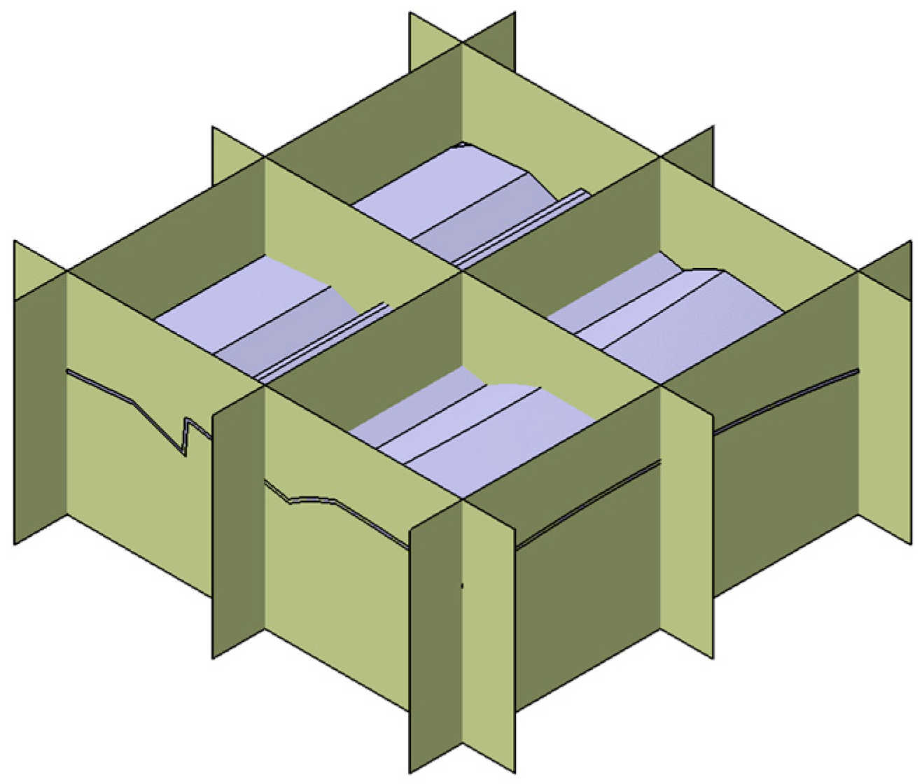
Accordingly, the remaining two sides of the segment were equipped with a rabbet. The concept of positioning both interfaces allowing for the overall assembly is shown in
Figure 7. With this arrangement, the assembly of all segments can be done in a plane perpendicular to the cutting direction. The position and implementation of the pin connections cannot be determined at this stage and are explained in the aggregated design.
After a detailed analysis of the solution space for the sub-functions of the developed method with respect to the requirements list, solution principles for the two main functions of segmentation and joining were successfully developed. The next step in the development methodology according to VDI 2221 [
15] is the creation of an overall concept. The preliminary considerations took place in a two-dimensional representation to reduce the complexity. The implementation of an overall concept requires the combination of the partial solutions in a three-dimensional design space. In the following, the overall concept is presented on a complex and three-dimensional example geometry for an illustrative presentation.
5. Concept Integration and Overall Design
The overall design integrated the partial concepts in a collaborative manner to ensure a functionality with respect to the requirements. In the following, an overview of the design and its distinctive features is given and visualized on an example (
Figure 8). The execution of the method leading to this assembly is described in
Section 6.
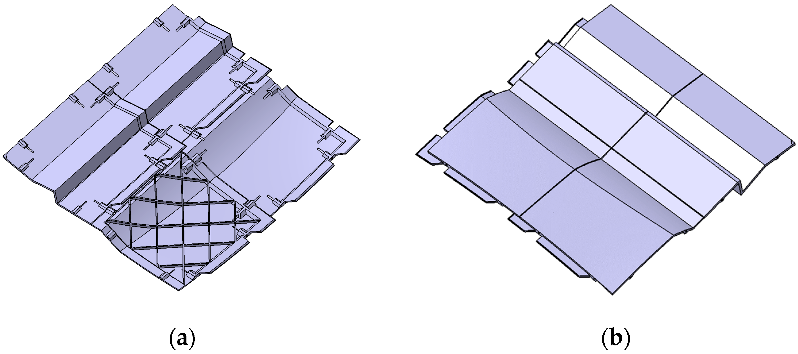
The example used for presentation is a thin-walled geometry with complex design elements (
Figure 8a). These include a surface curved in two spatial directions and a sharp-edged offset. The example part measures approximately 350 mm × 350 mm and has a wall thickness of 3 mm. With the developed method, the part is successfully divided into four segments (
Figure 8a). The main design elements of a segment are labeled in
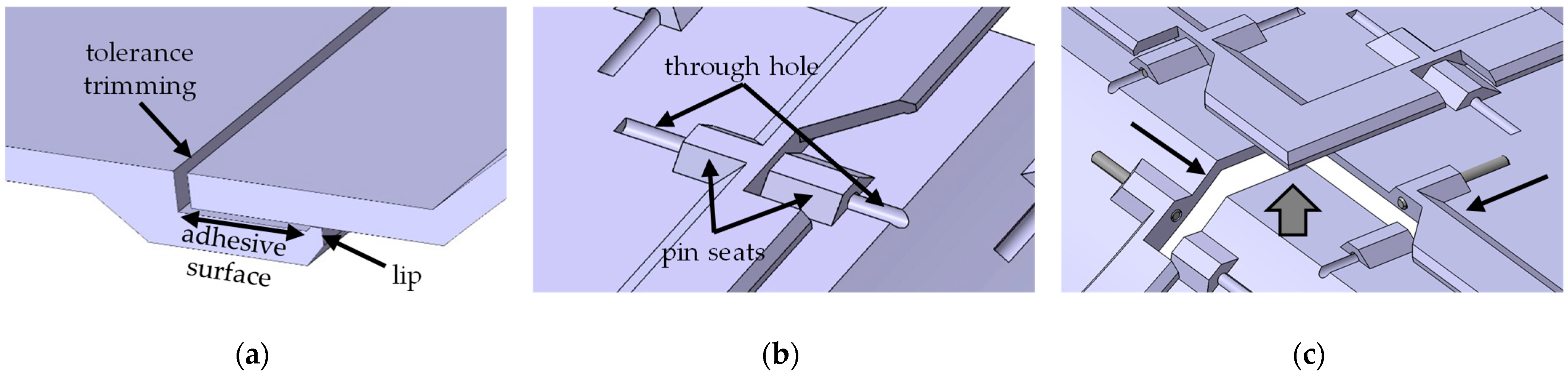
Figure 8b. For the illustration of the joining geometry, all four sides of each segment are equipped with the joining geometry. On a final part, the joint geometry is not present on the outer sides of a part, as no further segments connect.
The hybrid joining geometry combines a joggle lap for adhesive joining and pin seats for press fitting. Each segment has a circumferential rabbet on two adjacent joint sides and a tongue around the other two joint sides. The rabbet and tongue follow the exact part geometry. Each rabbet connects to a tongue of an adjacent segment and vice versa to form the joggle lap to allow force transmission (
Figure 9a). Furthermore, the circumferential course of the rabbet connects diagonal neighbors via their corners. The rabbet consists of an adhesive surface and a lip along its leading edge. This lip ensures a defined adhesive thickness between the mating surfaces.
Furthermore, the tongue is trimmed by a defined distance in the X-direction. This creates a gap between two segments that allows for tolerance compensation when pressing two segments together (
Figure 9b). If the dimensions of a segment deviate either in positive or negative X-direction, controlling how far the segments are pressed together allows adaptation to the desired overall part dimensions.
Each side of a segment is equipped with two pin seats for press fitting and defined positioning in relation to the adjacent segments (
Figure 8b). On the sides with a tongue, the pin seats are placed on top of the tongue. Therefore, the rabbet has cutouts at their location to allow for alignment. In addition, the positioning of the pin seats on top of the tongue increases the contact area to the print bed, which improves stability in production.
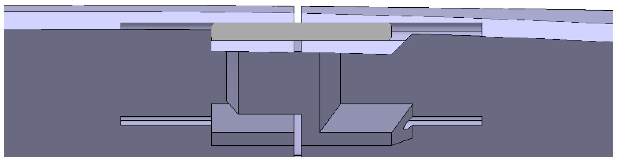
The through hole for receiving the dowel pins extends beyond the pin seats and allows the dowel pin to be fully recessed in one segment. The recess allows for assembly by preventing the interference of the dowel pins in situations like in
Figure 9, therefore being a prerequisite for composability. The process is further explained during assembly in
Section 6.3.
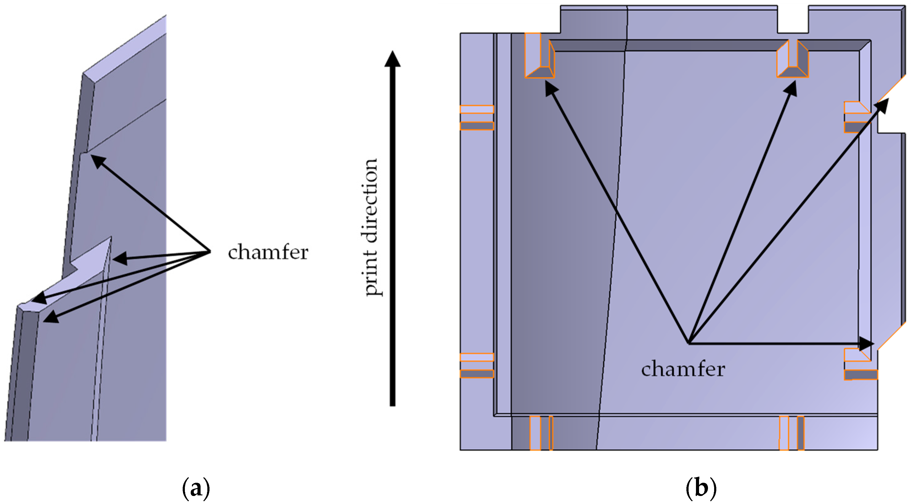
Finally, to be able to manufacture the segments additively without support structures, overhangs are prevented by chamfering kinks on the rabbet and pin seats, as well as chamfering the cutouts in the rabbet in the printing direction (
Figure 8).
Those are the key features of the joint design which are necessary for its functionality.
The universal application of these features is the key factor for the utility of the method and is presented in the following.
6. Method Execution
The method that universally derives the presented design is the main achievement of this paper. It represents a universal procedure capable of segmenting thin-walled parts regardless of their shape, minimizing design efforts while allowing for certain individual adaptations to a specific part geometry. It is divided into design, manufacturing, and assembly.
6.1. Design
Manufacturing and assembly convert the virtual design into a real assembly. Their outcome depends on the implementation of the design. Additive manufacturing and assembly rely on established processes. Accordingly, the novelty and the added value lie in the design implementation.
The design process is carried out in the CAD software CATIA V5 (Dassault Systèmes, Vélizy-Villacoublay, France) and uses its capabilities to achieve a mostly universal valid procedure. As a “direct manufacturing” process, additive manufacturing follows directly from the CAD files of the parts.
The example introduced in
Section 5 visualizes the individual steps. However, the explanations are valid in general.
6.1.1. Initial State
Designing starts with the virtual representation of the thin-walled part on which the method takes place. It must fit into the volume defined in
Section 4.6. The Z-axis of the coordinate system is oriented in the cutting direction and is, for most of the part, approximately perpendicular to the part’s top surface (
Figure 10).
Hereby, segmentation is completed. It represents the part-specific basis for the universal procedure and demands the most competence needed in the design phase. The designer needs an understanding of additive manufacturing and the requirements that the design needs to fulfill. If the segmentation complies with those requirements, the way is paved for successful implementation.
6.1.2. Segmentation
Segmentation is specific to the part and is primarily oriented to the shape of the part surface. The partitioning is sketched in the X/Y-plane. It is composed of a set of cut lines parallel to the X- or Y-direction. Their intersections form the rectangular shape for each segment, which gets cut out in the Z-direction further on (
Figure 10).
By adjusting the distance between those lines, the dimensions and position of each segment are defined.
Those dimensions can be freely chosen if the size of the segments does not exceed the height, length, and width of the build volume minus the width of the rabbet. For example, for an additive machine with a build volume of 200 mm × 200 mm × 200 mm and a rabbet width of 12.5 mm, a segment cutout cannot exceed 187.5 mm × 187.5 mm × 187.5 mm.
The segments should be designed to be as large as possible to reduce their number and to save time in the execution of the method. In addition, two conditions could require individual adjustment of the segment position. First, the manufacturability of all segments must be considered. If the surface of the segment has severe kinks or other complex geometries that cannot be manufactured in one of the possible print directions without overhangs, changing the segment position may allow printing without overhangs. If this method is not effective, printing with support structures should be considered.
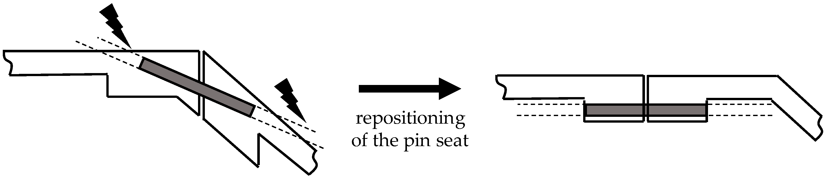
The second reason for adjusting the position of the cut lines is due to the pin seats. As the pins are straight, strong curvature or kinking in the surface of the part along the length of the pin hole hinder their usage (
Figure 11). If no suitable positions for the pin seats along the cutting edge of two segments exist, repositioning the cutting lines is necessary. As a further example of the reaction to a specific part geometry, consider the interior trim part presented in
Section 6.4.
Once the cut lines are finalized, they are extruded in the Z-direction. This creates the planes to cut out the individual segments (
Figure 11). The cutting planes are named in alphabetical order in the X-direction and in ascending numerical order in the Y-direction.
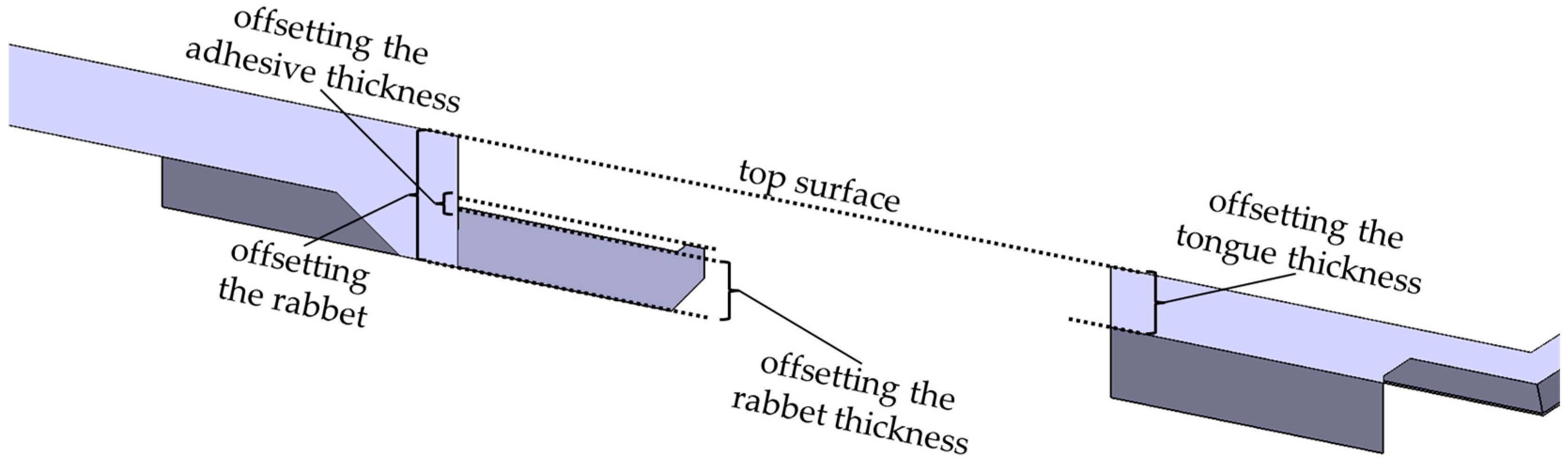
6.1.3. Surface Offsets
In this step, surface offsets, which are used in the following to form the joint geometry of the part’s main top and bottom surface, are created. They are the key element, which enables the rabbet and tongue to universally follow the progression of the part geometry. The areas of the rabbet and tongue resulting from the surface offsets are presented in
Figure 12. Accordingly, the values of the respective offsets determine the thickness and depth of the rabbet, the adhesive thickness, and the thickness of the tongue.
6.1.4. The Master Segment
With the cutting planes and the offset surfaces in place, the part is ready for designing the “master” segment. It is the first segment that is designed and serves as a base to derive each further segment. For this segment, the rabbet, tongue, and pin seats are designed in a parametric way and referenced to the cut planes bounding the segment. This enables the transfer of these elements to the other segments and automatically adapts them to the new geometry. This reduces the design effort for any following segment massively by requiring only minor individual adjustments instead of the manual recreation of the joints for every segment.
The cutout for the master segment is created by trimming the part with the four adjacent cut planes. Ideally a segment from the middle of the part, which does not include any outer edges, is chosen. This ensures that all segment sides are equipped with a joint for the future derivation to other segments. For segments with outer edges, it is easier to remove the unnecessary joints afterward.
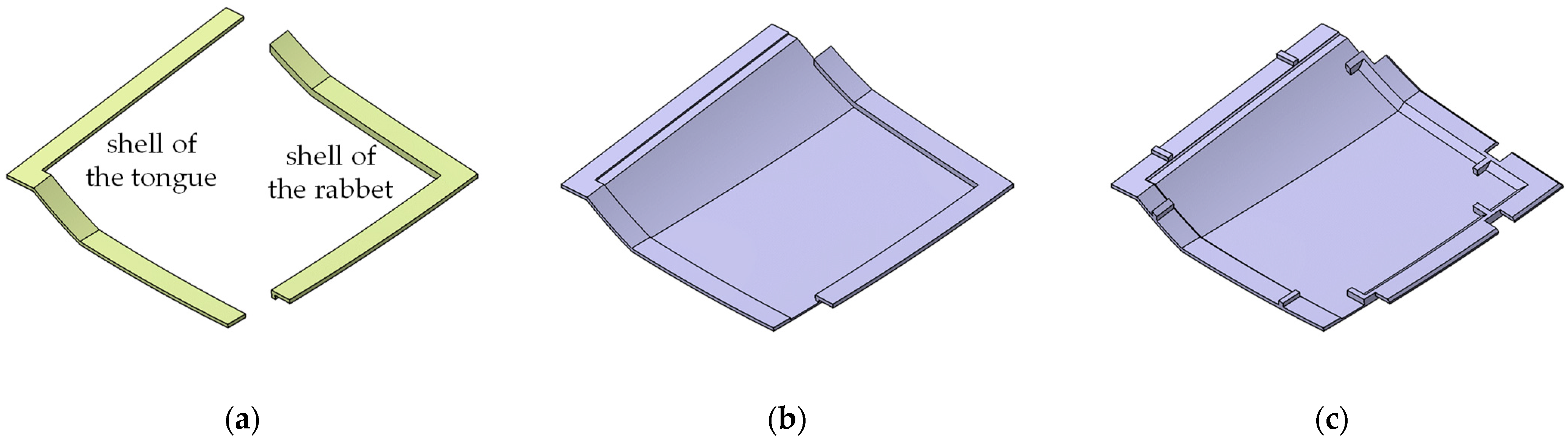
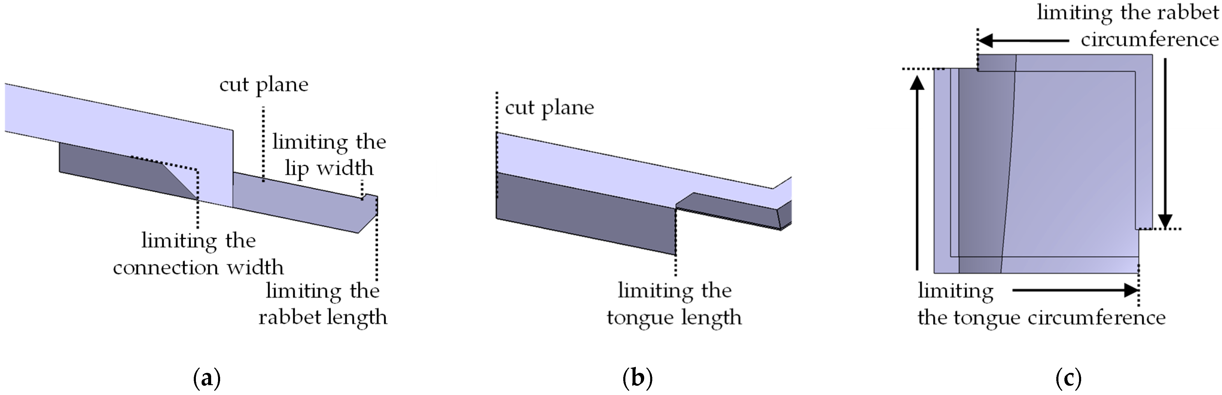
The rabbet and tongue are created as a surface model by the intersection of the created surface offsets with a series of boundary planes. The trimming of those surfaces creates a shell of the rabbet and tongue (
Figure 13a). Those boundary surfaces are derived from the cutting planes that bound the master segment. They represent displacements parallel to the cutting planes and are defined by the distance to them. The areas of the rabbet and tongue, which are derived from the boundary planes, are labeled in
Figure 13. Accordingly, the spacing of those determines the width of connection from the rabbet to the segment, the overlapping length, the width of the lip and the width of the tongue. Four further boundary surfaces determine the circumferential length of the entire rabbet and tongue. The dimensions of the rabbet and tongue are fully determined and adjustable via the entirety of the offset and boundary surfaces.
After deriving the shells of rabbet and tongue from trimming the surface offsets with the boundary planes, the shells are filled and joined to the cutout of the segment (
Figure 14b). Chamfers are used to avoid overhangs and cross-sectional jumps in the area of force transmission. The chamfering takes place at the transitions of the rabbet and the tongue toward the segment, along the leading edge of the rabbet and in the inner edge of the lip (
Figure 14a). Now, the segment has all geometric elements required for the joggle lap.
To complete the hybrid joint, designing the pin seats for the master segment follows. The thinness of the part requires material buildup for the pin holes. The material extrusion is based on a sketch in the X/Y-plane. This sketch defines the rectangular shape pin seats and the position of the pin seats along the edges of the segment. The pin seats should be well spaced with consideration of the fact that the part must be able to accommodate the full length of the through hole. Therefore, its shape should be as straight as possible in the area of the pin seats (
Figure 11). The width of the pin seats is dimensioned to deliver enough material to surround the pin holes, and their length equals half the length of the chosen dowel pins. Extruding the two-dimensional outline and trimming it with the surface offset for the underside of the rabbet make the pin seats flush with the rabbet and gives them a uniform thickness by following the run of the part’s surface (
Figure 15c). If the thickness of the pin seats is not sufficient for the chosen dowel pins, a separate offset to increase the thickness can be defined.
To finish the pin seats, the necessary cutouts to allow for the connection of two pin seats are added to the rabbet. The cutouts are referenced in direct relation to the position of the pin seats, and their width is large enough to allow for tolerance compensation during assembly (
Figure 15c).
In its current state, the master segment has all elements for the hybrid joint, except for the pin holes. Since the segment is cut out flush with the adjacent segments, tolerance trimming can only compensate for a shortening of the segment dimensions. To counteract exceeded nominal dimensions, the segment sides with a tongue are each trimmed with an additional boundary plane, which allows for tolerance compensation in the X- and Y-directions. The amount of trimming corresponds to the maximum tolerance generated by the manufacturing machine. Tolerance trimming completes the design of the master segment. All further adjustments are made individually to each segment derived from the master segment.
6.1.5. Lightweight Optimization
Before other segments are derived, additional designing on the master segment to enhance the performance of the assembly is possible. By referencing any custom design to the cut planes of the master segment, the design gets transferred from the master segment to all other segments.
One possible especially advantageous customization is lightweight optimization. Introducing a grid of ribs to the back side of the segments can optimize the mechanical performance of the segment and, thus, of the entire assembly. A thinner segment combined with a rib structure saves weight, which in return reduces material, time, and costs for additive manufacturing. Manufacturing a similar design with conventional processing would be extremely complex and costly. This is one of the advantages of implementing rapid technologies.
In
Figure 16a, a diamond grid structure is applied to one of the segments. This structure is chosen because it introduces no further overhangs and reduces the weight of the segment by approximately 25 % through a reduction in wall thickness from 3 mm to 1.5 mm. The process for designing this structure is similar to the procedure for the pin seats and has endless possibilities as long as manufacturability is kept in mind.
6.1.6. Segment Derivation
With the completion of the master segment, the derivation of the remaining segments begins. Therefore, a copy of the master segment is created. Because all design elements are referenced to the cut planes bounding the master segment, changing the cut planes referenced in the previous commands to those of another segment is sufficient to transform the copy into any other segment. A refresh lets the CAD software automatically calculate the new segment with all design elements adapted to its specific geometry. This process is repeated until all segments are derived.
Due to the individual geometry of each segment, specific adjustments may be necessary. This includes adjusting the position of the pin seats to allow for accommodation of the dowel pins (
Figure 11) as well as removing unnecessary joining geometry around the outer sides of the overall assembly. After the position of all joining elements is finalized, the remaining overhangs in the segment-specific printing direction are eliminated via chamfering. This includes the rear surfaces of the pin seats at the top of the segment and the upper edges of the cutouts for the pin seats (
Figure 14b). Additionally, the sides of the pin seats are chamfered for further strengthening.
6.1.7. Through Holes
Designing the through holes for the press fitting of the dowel pins is the last step to complete construction. The hole is oriented in such a way that it does not cut through the top of the part and lays as centered as possible inside the pin seat (
Figure 17). This orientation is individual for each pin seat. Therefore, it is not integrated into the master segment and designed separately. The holes have the length of the dowel pins and the diameter for the required pressing. With the completion of every through hole for each segment, the design of the assembly is completed.
6.1.8. Final Design
As the result of the design phase, the assembly is a virtual representation of the original part made of segments (
Figure 16b). From there, manufacturing starts. To avoid errors in manufacturing or problems during assembly, each individual segment as well as the overall assembly should be checked with respect to the requirements and design guidelines of this paper. Early adjustments save costs and time at an early stage.
6.2. Manufacturing
Additive manufacturing is based on the CAD files of the segments. For further information, please refer to the technical literature [
13,
20].
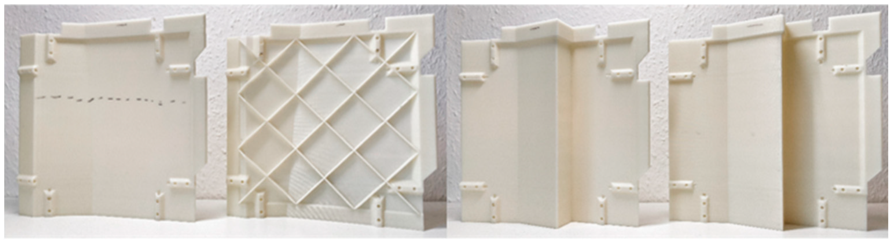
To validate the method, the four segments of the example were successfully manufactured in ABS on an FDM machine. Two of the segments have a regular wall thickness of 3 mm. The other two segments make use of individual customization. One segment has an increased wall thickness of 4 mm, while the other segment has a reduced wall thickness of 1.5 mm and is equipped with the diamond-grid structure (
Figure 18).
6.3. Assembly
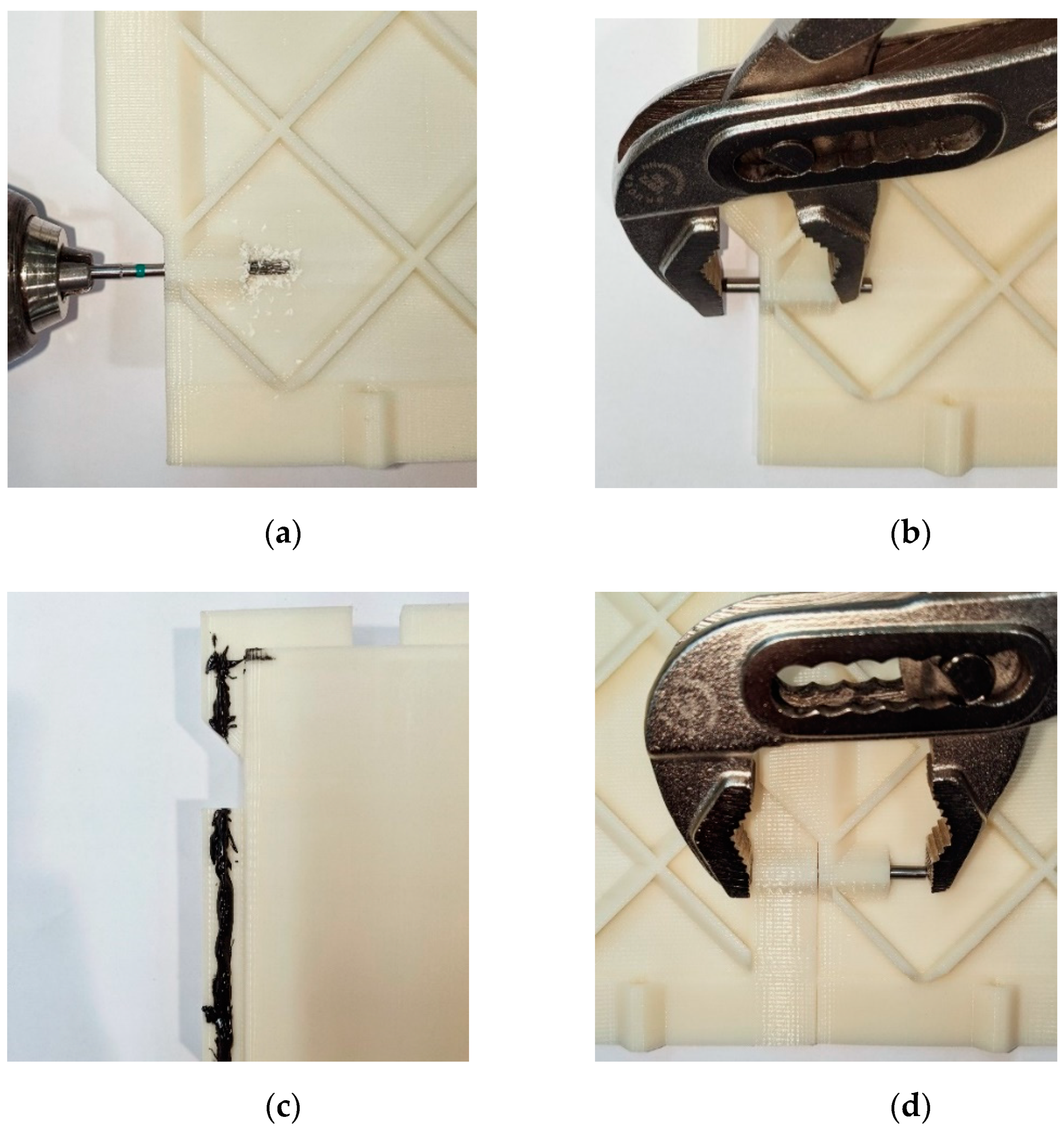
The hybrid joint design allows for two variants of assembly. Besides full assembly combining adhesion and press fitting of the hybrid joint, pre-assembly without gluing and solely based on press fitting is possible. Press fitting provides enough stability to validate the assembly and check the overall dimensions.
Pre-assembly begins with reworking the through holes. Reaming them brings them to the required dimension for the press fitting. In the second step, two segments that belong together are chosen. With the aid of pliers, two dowel pins are pressed into the corresponding pin seats on the joining side of one of the segments until they are recessed. During the alignment of both segments, the dowel pins are pressed from one segment into the other segment until fully seated in both pin seats attaching both segments together. Then, an adjacent segment is selected, and the procedure is repeated until all segments are joined to form the desired overall part. Press fitting holds the part together for handling during control and validation, while disassembly is still possible. During validation, the part’s overall dimensions are measured, and tolerance compensation takes place. By widening or reducing the gap between the individual segments, local dimensional deviations are reduced to the required specifications of the overall assembly. This can be done with the aid of a feeler gauge.
Furthermore, the pre-assembled part can be used for an installation test without load. The part can then react to dimensional deviations of the joining partner within a certain range by the means of tolerance compensation. The extent to which this is possible depends on the tolerance trimming and overlap length in the design of the segments. If no problems arise during pre-assembly, the part is suitable for final assembly.
Final assembly follows the same steps as pre-assembly with the additional application of adhesive to the rabbet of the segment before alignment. Subsequent pressing of the dowel pins results in a fixed bond until cured. The choice of adhesive depends on the material and needs a sufficient working time to allow for tolerance compensation before hardening. Based on the research of Arenas et al. [
13], a polyurethane adhesive is chosen to assemble the example segments made of ABS (
Figure 19).
Furthermore, installing the entire assembly and curing it in its final position are possible. After curing of the assembly, the bond is completed and has its final properties. The final assembled part is presented in
Figure 20.
6.4. Application—Proof of Concept
The investigations in this paper were carried out as part of the UNICARagil project [
10]. The aim of the project is the development of automated vehicle concepts with a modular and scalable basis. One of these vehicles is the “autoTAXI” [
24], an autonomous vehicle concept, whose interior is tailored to the needs and activities of the occupants. The interior trim parts were constructed based on this design concept. It envisages leathering of most of the trim parts. The developed method is used to manufacture the base parts for leathering. The leathering conceals gaps between the individual segments and therefore further improves the surface finish.
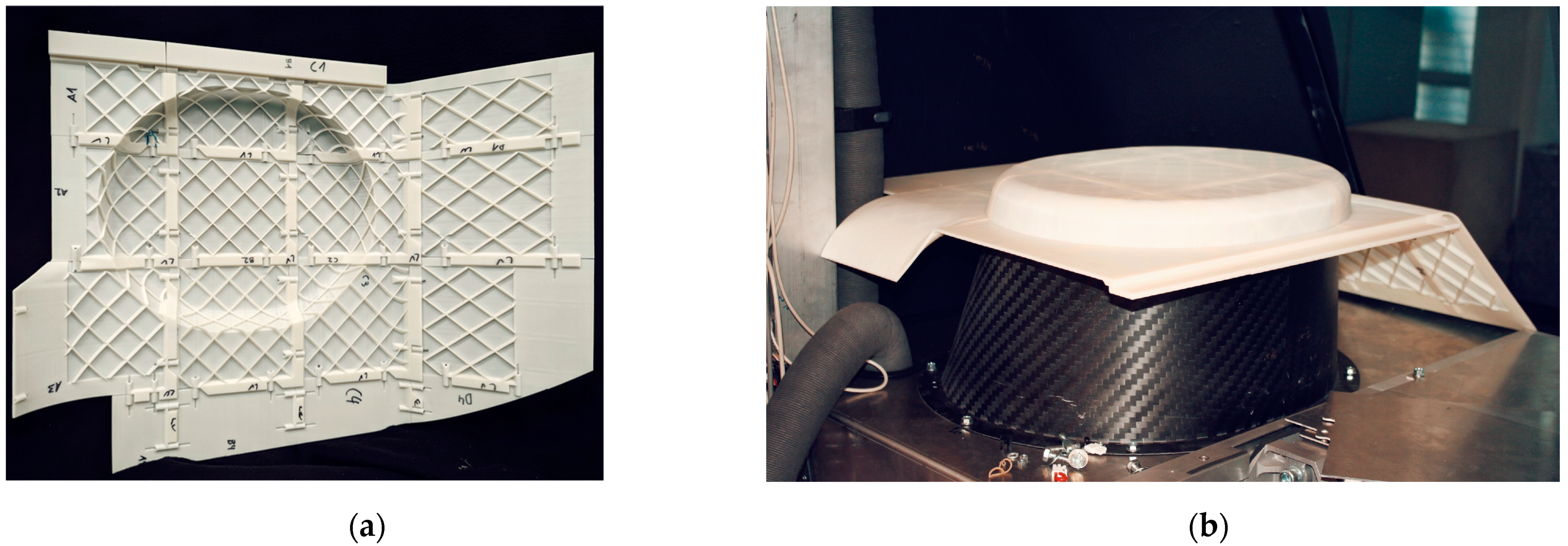
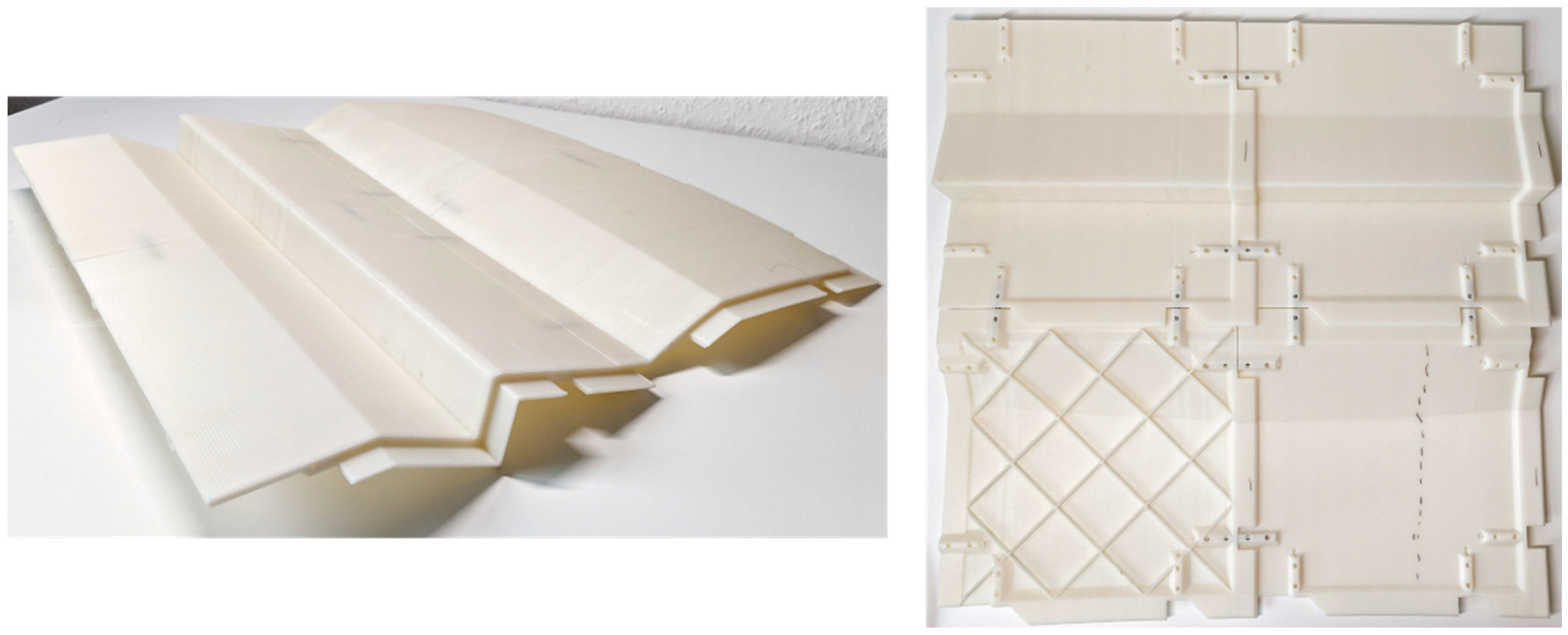
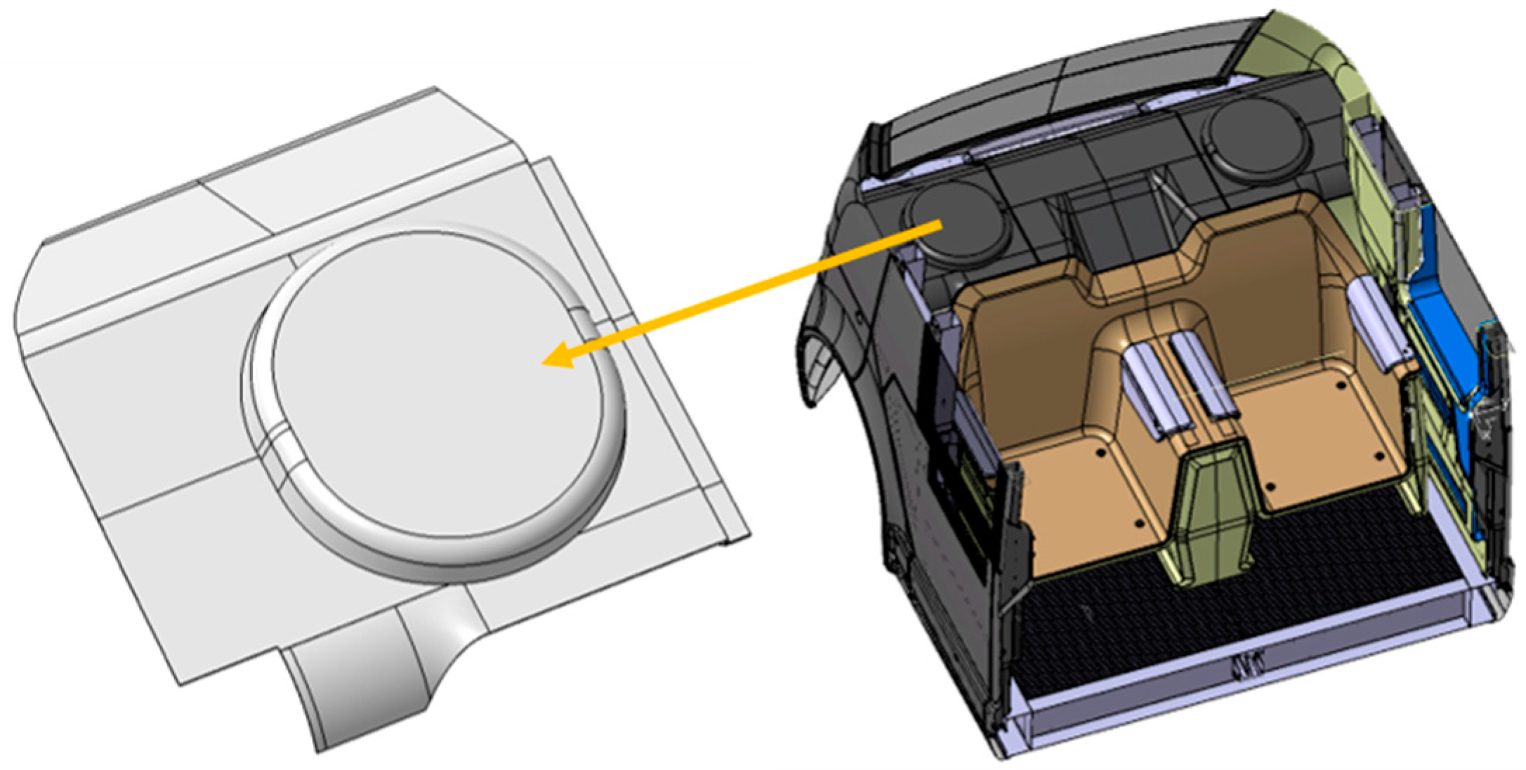
One of the first trim parts based on the developed method was the side panel of the luggage rack (
Figure 21). Due to the complex shape of the surface with a circular protrusion, the part proved to be well suited for further validation of the method. The angle of the kink at this protrusion exceeds 60° all around, which is critical for additive manufacturing, due to being an overhang from the perspective of segment orientation. In general, manufacturing overhangs with the help of support structures is an option. However, the capabilities of the developed method made it possible to avoid overhangs. In this way, the time, cost, and quality advantages of an overhang-free design was exploited.
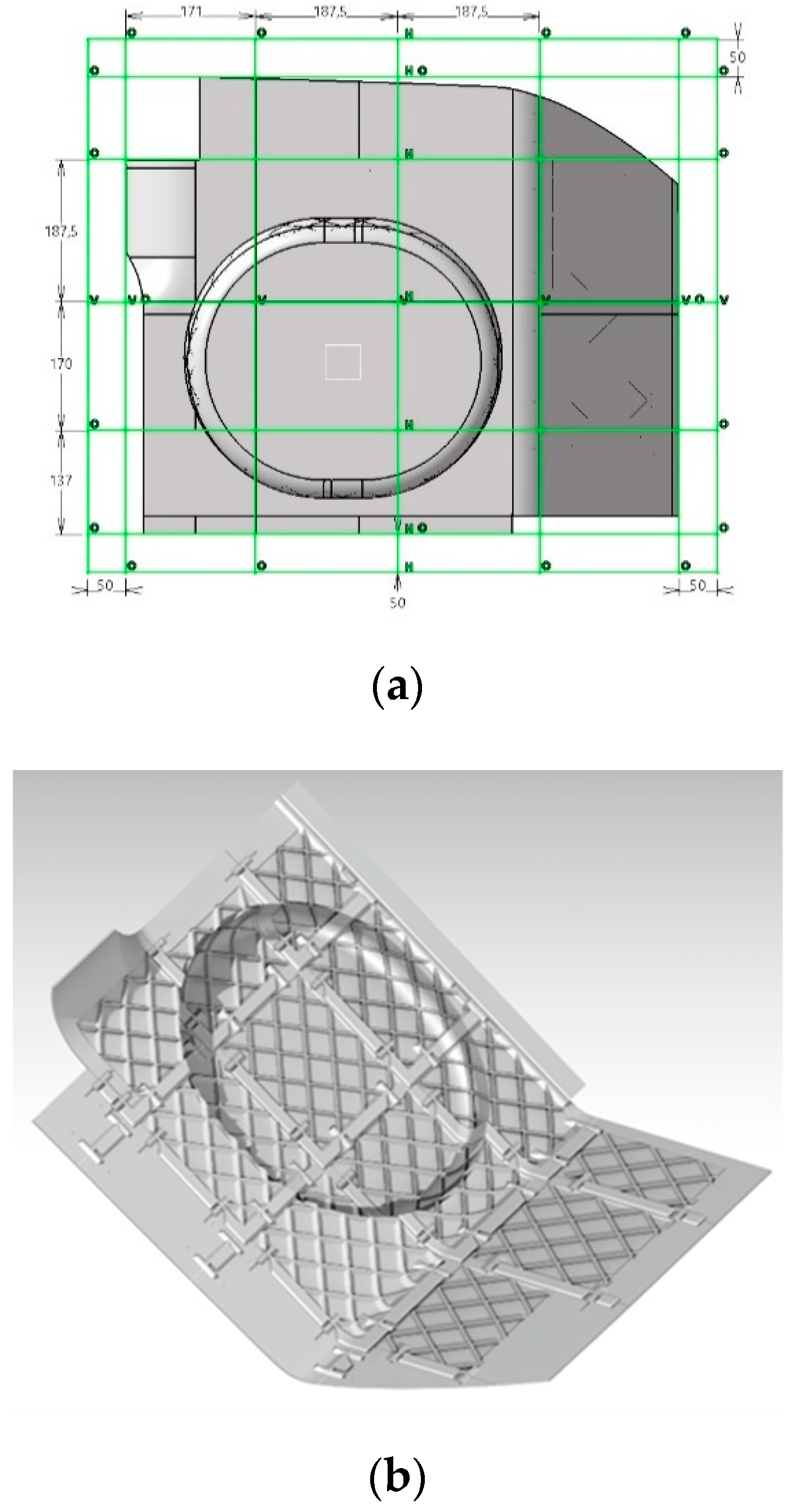
Design implementation of the method began with the definition of the cut lines. Because these lines determine the geometry of the individual segments, they are crucial to avoid overhangs. The final layout of the cut lines is shown in
Figure 22a.
Segmentation begins around the oval-shaped offset because it presents the greatest challenge for manufacturing. The round offset is distributed over eight segments. Of these eight segments, the four corner segments, where the contour curves around the corner of the segments, are critical. The cut lines were chosen so that the curvature does not exceed a 60° angle in one of the possible printing directions. This was possible for three of the four segments due to the uniform placement of the rabbet and tongue on each segment. The other segment was oriented with the rabbet positioned on the build plate of the additive machines and required a small number of support structures at the shoulder of the rabbet (
Figure 5).
Another challenge was the strong curvature in the right-hand area of the part. Here, the parallel cutting line must have sufficient clearance from the curvature to accommodate the dowel pins for press fitting. The remaining geometry did not pose a challenge for the application of the method.
Defining the cut lines was the most demanding task in the application of the method. Designing the master segment and deriving the other segments followed the procedure defined in
Section 6.1. During these steps, the method took advantage of the defined possibility of lightweight construction using the diamond-grid structure described in
Section 6.1.5.
After completion of the designing phase of the method, modifications for mounting in the vehicle and leathering were added to the design. The fastening was done with the help of aluminum brackets, which allow screwing to the vehicle, and were glued onto the part. To provide the aluminum angles with an adhesive surface, solid material replaced the diamond grid at the corresponding area around the boundary of the part. The same applied to the leathering which was folded around the part contour and glued in place. With these adjustments, the design was finished (
Figure 22b).
Manufacturing took place via FDM printing out of ABS. All segments were successfully additively manufactured. Tolerance trimming was set with respect to the capabilities of the additive machine, and no further post processing was required. Checking the dimensions of each segment verified this. The tolerance trimming compensated all deviations in positive direction, and the final dimensions of each segment were 0.2 mm to 1.2 mm smaller than the specified values without trimming. This is wanted and the prerequisite to implement the tolerance compensation during assembly.
Assembly started with pre-assembly without adhesive as described in
Section 6.3. As expected, the overall dimensions of the part were smaller than specified before tolerance compensation took place (between −2.1 mm and −0.5 mm). By adjusting the gap between each segment with a feeler gauge, these dimensions were increased to specification and the gap size was noted. Placing the overall assembly at its defined position in the autoTAXI vehicle (
Figure 8b) verified the fitment in relation to the body-in-white. The part was approved and disassembled to allow for final assembly using adhesive.
For the final assembly, the same steps were repeated with the addition of adhesive (
Section 6.3). Afterwards, the part was left for curing. The final and fully assembled part is shown in
Figure 23.
7. Discussion and Outlook
The developed method was successfully applied on an example. Furthermore, the capabilities of the method were verified on an automotive interior trim part. To evaluate the potential of the method, it is reviewed against the requirements (
Table 1). Thereafter, concrete potentials for further application are derived. Finally, a conclusion is drawn about the suitability for prototyping.
7.1. Universal Application
This paper focused on the segmentation of parts that fit in a cubic space with arbitrary length and width, but height limited to the width of the build volume of the additive manufacturing machine (
Section 4.6). The potential for exceeding this space exists but requires further research.
Most of the other requirements were directed to the joining of the segments. The hybrid joint design consists of a combination of a joggle lap for adhesive joining and pin seats for press fitting. Regarding adhesion, the joggle lap fulfills the requirements for a universal application. Due to referencing to the part geometry, the adhesion surfaces follow the arbitrary course of the part’s surface. The pin seats in combination with dowel pins for press fitting fulfill this requirement to a certain extent. The prerequisite is that the shape of the part makes it possible to accommodate dowel pins in the area of joining. Because of the freedom in positioning of the pin seats along the cut lines as well as the positioning of the cut lines themselves, the pin seats can be easily adapted to the geometry. Nevertheless, the method cannot universally guarantee the accommodation of all pin seats. In cases where a specific pin seat cannot be accommodated by means of the method, additional design adjustment could be expedient.
7.2. Requirements for the Method
The basic requirements for the method itself are fully met. It produces a positioned joint that can simultaneously compensate for segment tolerances. Force transmission was designed according to the current state of the art, using an overlapping joint, and is supported by press fittings. In addition, force transmission takes place along the entire joining surface, which prevents relative movement between the segments. To convert the qualitative requirements into quantitative values, further research and testing are needed. Since the method is parametric in its design, the dimensions of the joint can be tailored to a specific load case.
Regarding additive manufacturing, the method allows for production without overhangs. One advantage of segmentation in combination with additive manufacturing is the design freedom of individual segments. The use of a diamond-grid structure saves weight and increases the stiffness of the segments.
7.3. Requirements for the Final Assembly
At the current state of research, the method was not evaluated in terms of dimensional accuracy or the mechanical performance of the overall assembly. Those features are highly dependent on the quality and performance of the additive machines, which is not the topic of this paper. The method provides the means to achieve an assembly performing like a solid part because it is parametrically designed. This allows free adjustment of the dimensions of each joint element. The dimensions needed to perform like a solid part are specific to the use case and basis of comparison of assembly and solid part. Therefore, further research, manufacturing, investigation, and testing of suitable test specimens are necessary.
7.4. Time Consumption
In this method, designing the segments is an additional step required to produce the overall part in the form of an assembly and presents the main difference from conventional processing. The production and assembly of the segments can be compared with the effort required to produce a mold as well as hand lay-up as the comparative process in conventional prototyping of large area thin-walled parts.
For the method to be competitive, the additional effort of designing should be kept as low as possible. In the construction of the autoTAXI luggage rack, the time required was composed as follows. The definition of the cut lines, segmentation, and the creation of the master segment took 10.5 h. The derivation and adjustment of each additional segment averaged about 1 h. For the implementation of the entire part with 16 segments, an effort of about four working days (28 h) was required. In the UNICARagil project, this additional effort is justified by the cost advantage over the conventional hand lay-up process.
7.5. Costs
The cost of the method depends on the basis of assessment. Manufacturing costs, excluding labor costs, are determined by the material costs in additive manufacturing. Power consumption for the additive machine is negligible. In the following, a market price for the filament from Ampertec of approx. 20 EUR/kg is assumed for the production in ABS [
25]. The luggage rack requires about 2 kg of ABS and, thus, incurs costs of about EUR 60 for additive manufacturing, including costs for dowel pins and adhesive.
For hand lay-up, the cost for manufacturing a milled mold is estimated to be about EUR 6000. For both processes, labor costs are excluded. The cost advantage of the developed method is obvious in this comparison. The manufacturing cost of the mold is the largest share of the cost for hand lay-up. The integration of rapid technologies in the form of additive manufacturing saves those costs. The exact comparison of the costs for material and labor for laminating the mold, compared to the material and labor costs for design and assembly using the developed method, are to be investigated in the future.
7.6. Potential for Application
Up to this point, the use of the developed method for the direct manufacture of large-area, thin-walled parts was investigated. Here, the suitability of the method beyond this focus is illuminated.
Fiber-reinforced plastics, as in hand lay-up, allow for higher stiffness at lower weight compared to pure plastic parts. During hand lay-up, high costs and lead times are incurred to manufacture the necessary molds [
26]. Instead of replacing the hand lay-up process, the developed method could be used as a rapid tooling technique for the creation of negative molds. In the following, state-of-the-art research on rapid tooling of molds is presented.
Hornfeck [
26] was able to halve the material costs and lead time by using vacuum lamination with molds made of ABS using FDM instead of milling the molds.
Dippenaar and Schreve [
27] used additive manufacturing to create two mold halves and a core for manufacturing a propeller blade. This achieved a tolerance of ±1 mm, while halving the cost and time, compared to CNC manufacturing of the molds.
In recent years, additive processes have become more established, process and material costs have decreased further, and material variety has increased. Bere et al. [
28] achieved parts with a tolerance of ±1 mm with molds made from polylactic acid (PLA) and ABS using the FDM process. A mold made from PLA is estimated to cost ten times less than an aluminum mold and 8.6 times less than an epoxy mold. It also has about 15 times lower mass than the aluminum mold and about 6.6 times lower mass than the epoxy mold.
As for direct manufacturing, the state of the art in rapid tooling is limited to parts in the scale of the build volume, which can be manufactured with one- or two-part additive molds. For large-scale parts, the developed method could be used to create a segmented negative mold.
Another potential application is a hybrid material joint. The shell of the desired part is produced using the presented method and laminated on one side in a solid bond. This approach would combine the advantages of both methods. In addition, due to the thin-walled design of the segmented shell, vacuum curing could be used to bond and press the laminate and the shell together.
7.7. Conclusions
The developed method was proven to be effective in its implementation. Due to the hybrid joint design, it created a connection that simultaneously positions, transmits forces, and compensates for tolerances. Due to the adaptive design of the method, it offers a high potential for the universal application while requiring little design effort. Due to the unlimited possibilities of the design of three-dimensional bodies, the application cannot be guaranteed. Overall, it fulfills the aim of using additive manufacturing economically to produce thin-walled parts that exceed the build volume of additive manufacturing machines. The application was verified using an automotive trim part, which can be considered geometrically complex due to its shape, thin wall, and size.
The overall aim of achieving the mechanical characteristics of a solid part needs further research. With the parametric design and the results of existing research on the bonding of additive materials [
7,
13,
19], the prerequisites for a bond that achieves the strength of the material were established.
We are convinced that we created a possibility to quickly produce complex geometries that exceed the usual build volume of additive machines. This can save time and costs in prototyping and thus lead projects, such as the presented autoTAXI, to success. Furthermore, our design method could be a tool for modern design methodologies based on continuous prototyping.


