
Inertial Measurement Units (IMUs) in Mobile Robots over the Last Five Years: A Review


Abstract
:1. Introduction
2. Literature Report
2.1. Bibliography Selection Protocol
- Research QuestionQ1: What are the IMU models used in the last 5 years?Q2: What are the properties, main features, structure, response speed, connectivity and protocols of IMUs over the last 5 years?Q3: What are the comparative differences in their characteristics?Q4: What are the most used IMUs?
- Research Database
- Rejection Criteria
- K1: Publications must be written between the year 2016 and 2020 i.e., the last five years.
- K2: Citations per year must be more than 4.
- K3: Citations must be over 20.
- Quality CriterionK4: The publication should refer to mobile robots.
- Acceptance CriterionK5: Publications should refer the company or IMU model used in their research.
- Special CriterionS1: After the K1 through K5 application the number of publications per publisher should be at least 2.
2.2. Research Execution

| Manufacturer | Model | Voltage | Output Data Rate (HZ) | Gyroscope Range (°/s) | Accelerometer Range (g) | Magnetometer Range (G) | Power Consumption (mW) | Structure |
|---|---|---|---|---|---|---|---|---|
| Xsens | Mti-1 | 2.19–3.6 | ≤2000 | ±2000 | ±16 | - | <100 | Gyr, Acc, |
| Mti-10 | 4.5–3.4 | ≤2000 | ±450 | ±20 | ±8 | 400–550 | Gyr, Acc, Mag | |
| Mti-100 | 4.5–3.4 | ≤2000 | ±450 | ±20 | ±8 | 450–950 | Gyr, Acc, Mag | |
| Mti-600 | 4.5–24 | 400–2000 | ±450 | ±20 | ±8 | 450–950 | Gyr, Acc, Mag, Bar | |
| InvenSense | MPU-9150 | 2.4–3.5 | 8000 | ±250, ±500, ±1000, ±2000 | ±2, ±4, ±8, ±16 | ±12 | 0.24–0.35 | Gyr, Acc, Mag |
| MPU-9250 | 2.4–3.5 | 8000 | ±250, ±500, ±1000, ±2000 | ±2, ±4, ±8, ±16 | ±48 | 1.8–2.62 | Gyr, Acc, Mag | |
| MPU-6050 | 2.4–3.5 | 1000 | ±250, ±500, ±1000, ±2000 | ±2, ±4, ±8, ±16 | - | 9.5–13 | Gyr, Acc | |
| ICM-20948 | 1.71–1.95 | 9000 | ±250, ±500, ±1000, ±2000 | ±2, ±4, ±8, ±16 | ±49 | 2.5 | Gyr, Acc, Mag | |
| ICM-42605 | 1.7–3.6 | 8000 | ±125, ±250, ±500, ±1000, ±2000 | ±2, ±4, ±8, ±16 | - | 1.1–2.3 | Gyr, Acc | |
| ICM-20602 | 1.7–3.6 | 8000 | ±250, ±500, ±1000, ±2000 | ±2, ±4, ±8, ±16 | - | 1.1–2.3 | Gyr, Acc | |
| ITG-3050 | 2.1–3.6 | - | ±250, ±500, ±1000, ±2000 | - | - | 12.4–21.2 | Gyr | |
| ITG-3200 | 2.1–3.6 | 8000 | ±2000 | - | - | 13.65–23.4 | Gyr | |
| MPU-3050 | 2.1–3.6 | 3.9–8000 | ±250, ±500, ±1000, ±2000 | - | - | 13 | Gyr | |
| MPU-3300 | 2.37–3.46 | 3.9–8000 | ±225, ±450 | - | - | 13 | Gyr | |
| ICM-20608-G | 1.71–3.45 | 4–8000 | ±250, ±500, ±1000, ±2000 | ±2, ±4, ±8, ±16 | - | - | Gyr, Acc | |
| Microstrain | 3DM-GX5-10 | 4–36 | 1–1000 | ±75, ±150, ±300, ±900 | ±2, ±4, ±8, ±20, ± 40 | - | 300 | Gyr, Acc, TS |
| 3DM-CX5-10 | 3.2–5.2 | 1–1000 | ±75, ±150, ±300 ±900 | ±2, ±4, ±8, ±20, ±40 | - | 300 | Gyr, Acc, TS | |
| 3DM-CV5-10 | 3.2–5.2 | 1–1000 | ±250, ±500, ±1000 | ±2, ±4, ±8 | - | 360 | Gyr, Acc, TS | |
| Pixhawk | Pixhawk 4 | 4.75–5.2 | - | ±250, ±500, ±1000, ±2000 | ±2, ±4, ±8, ±16 | ±16 (x,y), 25y | 360 | Gyr, Acc, Mag |
| Pixhawk 3 Pro | 3.3 | - | ±250, ±500, ±1000, ±2000 | ±2, ±4, ±8, ±16 | ±4, ±8, ±12, ±16 | 825 | Gyr, Acc, Mag, Bar | |
| Pixracer | - | - | ±250, ±500, ±1000, ±2000 | ±2, ±4, ±8, ±16 | ±8 | - | Gyr, Acc, Mag, Bar | |
| Pixhawk | - | - | ±245, ±500, ±2000 | ±2, ±4, ±8, ±16 | ±2, ±4, ±8, ±12 | - | Gyr, Acc, Mag, Bar | |
| ADIS | ADIS16475 | 3–3.6 | 2000 | ±125, ±450, ±2000 | ±8 | - | 132–158 | Gyr, Acc |
| ADIS16495 | 3–3.6 | 4500 | ±125, ±500, ±2000 | ±8 | - | 267–320 | Gyr, Acc | |
| ADIS16465 | 3–3.6 | 2000 | ±125, ±500, ±2000 | ±8 | - | 450–950 | Gyr, Acc | |
| ADIS16490 | 3–3.6 | 4250 | ±100 | ±8 | - | 267–320 | Gyr, Acc | |
| ADIS16488 | 3.15–3.45 | 819 | ±450 | ±18 | ±2.5 | 240–262 | Gyr, Acc, Mag, Bar | |
| ADIS16445 | 3.15–3.45 | 820 | ±62, ±125, ±250 | ±5 | - | 1.8–2.62 | Gyr, Acc, Mag, Bar | |
| ADIS16448 | 3.15–3.45 | 819 | ±250, ±500, ±1000 | ±18 | ±1.9 | 239–262 | Gyr, Acc, Mag, Bar | |
| ADIS16480 | 3–3.6 | 2460 | ±450 | ±10 | ±2.5 | 841 | Gyr, Acc, Mag, PS | |
| ADIS16485 | 3–3.6 | 2460 | ±450 | ±5 | - | 650 | Gyr, Acc | |
| ADIS16362 | 4.75–5.25 | 819.2 | ±75, ±150 ±300 | ±1.7 | - | 245 | Gyr, Acc | |
| ADIS16365 | 4.75–5.25 | 819.2 | ±75, ±150 ±300 | ±18 | - | 120 | Gyr, Acc | |
| SparkFun | VR IMU Breakout—BNO080 | 1.65–3.6 | - | ±2000 | ±8 | - | 45 | Gyr, Acc, Mag |
| IMU Breakout—LSM9DS1 | 3.3 | - | ±245, ±500, ±2000 | ±2, ±4, ±8, ±16 | ±4, ±8, ±12, ±16 | 14.85 | Gyr, Acc, Mag | |
| SparkFun MPU-6050 | 2.4–3.5 | 1000 | ±250, ±500, ±1000, ±2000 | ±2, ±4, ±8, ±16 | - | 9.5–13 | Gyr, Acc | |
| ESP32 Thing Motion Shield | 3.3 | 80 | ±245, ±500, ±2000 | ±2, ±4, ±8, ±16 | ±4, ±8, ±12, ±16 | 13.2 | Gyr, Acc, Mag | |
| SparkFun LSM6DS3 | 1.71–3.6 | 1600 | ±125, ±245, ±500, ±1000, ±2000 | ±2, ±4, ±8, ±16 | ±2, ±4, ±8, ±12, ±16 | 2.1–4.5 | Gyr, Acc | |
| VectorNav | VN-100 | 3.2–3.5 (WOC) 12–34 (WC) | 800 | ±2000 | ±16 | ±2.5 | 185 (WOC), 200 (WC) | Gyr, Acc, Mag, PS |
| VN-110 | 3.2–3.5 (WOC) 12–34 (WC) | 800 | ±490 | ±15 | ±2.5 | <1000 (WOC), <2000 (WC) | Gyr, Acc, Mag, PS, AS | |
| VN-200 | 3.2–5.5 (WOC) 3.3–17 (WC) | 800 | ±2000 | ±16 | - | 445 (WOC), 500 (WC) | Gyr, Acc, PS | |
| VN-300 | 3.2–5.5 (WOC) 3.3–14 (WC) | 400 | ±2000 | ±16 | ±2.5 | <1250 (WOC), 1250 (WC) | Gyr, Acc, PS |
| Manufacturer | Model | Gyroscope (Nonlinearity, Sensitivity, Noise Density) | Accelerometer (Nonlinearity, Sensitivity, Noise Density) | Weight (g) | Dimensions (mm) | Connectivity Protocols | Software | Cost (€) |
|---|---|---|---|---|---|---|---|---|
| Xsens | Mti-1 | ±0.1% fs, 0.001°/s/g, 0.007°/s/√Hz | ±0.5% fs, -, 0.12 mg/√Hz | <1 | 12.1 × 12.1 × 2.55 | I²C, SPI, UART, Xbus | MT Software Suite | 135 |
| Mti-10 | ±0.03% fs, 0.006°/s/g, 0.03°/s/√Hz | ±0.1% fs, -, 0.06 mg/√Hz | 11 (WOC) 52 (WC) | 37 × 33 × 12 (WOC) 57 × 42 × 23.5 (WC) | RS232, RS485, RS422, UART, USB, Xbus | 800 | ||
| Mti-100 | ±0.01% fs, 0.003°/s/g, 0.01°/s/√Hz | ±0.1% fs, -, 0.06 mg/√Hz | 11 (WOC) 52 (WC) | 37 × 33 × 12 (WOC) 57 × 42 × 23.5 (WC) | RS232, RS485, RS422, UART, USB, Xbus | 1470 | ||
| Mti-600 | ±0.1% fs, 0.001°/s/g, 0.007°/s/√Hz | ±0.1% fs, -, 0.06 mg/√Hz | 11 (WOC) 52 (WC) | 37 × 33 × 12 (WOC) 57 × 42 × 23.5 (WC) | CAN, RS232, UART, Xbus | 450 | ||
| InvenSense | MPU-9150 | ±0.2% fs, 0.0076°/s/LSB, 0.005°/s/√Hz | ±0.5% fs, 0.061 mg/LSB, 0.4 mg/√Hz | - | 4 × 4 × 1 | I²C | SmartRobotics | 17 |
| MPU-9250 | ±0.1% fs, 0.0076°/s/LSB, 0.01°/s/√Hz | ±0.5% fs, 0.061 mg/LSB, 0.3 mg/√Hz | - | 3 × 3 × 1 | I²C, SPI | 11.5 | ||
| MPU-6050 | ±0.2% fs, 0.0076°/s/LSB, 0.005°/s/√Hz | ±0.5% fs, 0.061 mg/LSB, 0.4 mg/√Hz | - | 4 × 4 × 0.9 | I²C | 5 | ||
| ICM-20948 | ±0.1% fs, 0.0076°/s/LSB, 0.015°/s/√Hz | ±0.5% fs, 0.061 mg/LSB, 0.23 mg/√Hz | - | 3 × 3 × 1 | I²C, SPI | 13.5 | ||
| ICM-42605 | ±0.1% fs, 0.061°/s/LSB, 0.0038°/s/√Hz | ±0.1% fs, 0.488 mg/LSB, 0.07 mg/√Hz | - | 2.5 × 3 × 0.91 | I²C, SPI | 6 | ||
| ICM-20602 | ±0.1% fs, 0.0076°/s/LSB, 0.004°/s/√Hz | ±0.3% fs, 0.061 mg/LSB, 0.1 mg/√Hz | - | 3 × 3 × 0.75 | I²C, SPI | 5 | ||
| ITG-3050 | ±0.2% fs, 0.0076 o/s/LSB, 0.001 o/s /√Hz | - | - | 4 × 4 × 0.9 | I²C | 2.5 | ||
| ITG-3200 | ±0.1% fs, 6.95 × 10⁻⁵°/s/LSB, 0.003°/s/√Hz | - | - | 4 × 4 × 0.9 | I²C | 10.5 | ||
| MPU-3050 | ±0.2% fs, 0.0076°/s/LSB, 0.01°/s/√Hz | - | - | 4 × 4 × 0.9 | I²C | 7 | ||
| MPU-3300 | ±0.2% fs, 0.0068°/s/LSB, 0.005°/s/√Hz | - | - | 4 × 4 × 0.9 | I²C, SPI | 35 | ||
| ICM-20608-G | ±0.1% fs, 0.0076°/s/LSB, 0.008°/s/√Hz | ±0.5% fs, 0.061 mg/LSB, 0.25 mg/√Hz | - | 3 × 3 × 0.75 | I²C, SPI | 6.5 | ||
| Microstrain | 3DM-GX5-10 | ±0.02% fs, -, 0.005°/s /√Hz | ±0.02% fs, -, 0.02 mg/√Hz | 16.5 | 36 × 36.6 × 11 | RS232, LXRS Protocol | SensorConnect | 710 |
| 3DM-CX5-10 | ±0.02% fs, -, 0.005°/s/√Hz | ±0.02% fs, -, 0.02 mg/√Hz | 8 | 38 × 24 × 9.7 | RS232, LXRS Protocol | 710 | ||
| 3DM-CV5-10 | ±0.06% fs, -, 0.0075°/s/√Hz | ±0.04% fs, -, 0.1 mg/√Hz | 11 | 38 × 24 × 9.7 | TTL serial, LXRS Protocol | 710 | ||
| Pixhawk | Pixhawk 4 | ±0.1% fs, 0.0076°/s/LSB, 0.006°/s/√Hz | ±0.5% fs, 0.61 mg/LSB, 0.15 mg/√Hz | 15.8 | 44 × 84 × 12 | PWM, SBUS, I²C, SPI, CAN | Open Source Autopilot | 230 |
| Pixhawk 3 Pro | ±0.1% fs, 0.0076°/s/LSB, 0.004°/s /√Hz | ±0.3% fs, 0.061 mg/LSB, 0.1 mg/√Hz | 45 | 71 × 49 × 23 | PWM, SBUS, I²C, SPI, SUMD, PPM | 260 | ||
| Pixracer | ±0.1% fs, 0.0076°/s/LSB, 0.008°/s/√Hz | ±0.5% fs, 0.061 mg/LSB, 0.25 mg/√Hz | 10.5 | 36 × 36 | UART, USB, PWM, SBUS, I²C, SPI, JTAG, PPM, ST24 | 265 | ||
| Pixhawk | ±0.2% fs, 0.0076°/s/LSB, 0.005°/s/√Hz | ±0.5% fs, 0.061 mg/LSB, 0.4 mg/√Hz | 38 | 50 × 15.5 × 81.5 | UART, PWM, SBUS, I²C, SPI, PPM, USB, ST24, SUMD | 230 | ||
| Analog Devises | ADIS16475 | ±0.2% fs, 0.00625°/s/LSB, 0.003°/s /√Hz rms | ±0.25% fs, 3.8 × 10⁻⁶ mg/LSB, 0.023 mg/√Hz rms | 1.3 | 11 × 15 × 11 | SPI | CoolVision SDK | 860 |
| ADIS16495 | ±0.2% fs, 9.53 × 10⁻⁸°/s/LSB, 0.002°/s/√Hz rms | ±0.25% fs, 3.8 × 10⁻⁶ mg/LSB, 0.017 mg/√Hz rms | 42 | 47 × 44 × 14 | SPI | 2500 | ||
| ADIS16465 | ±0.2% fs, 0.00625°/s/LSB, 0.002°/s/√Hz rms | ±0.25% fs, 3.8 × 10⁻⁶ mg/LSB, 0.023 mg/√Hz rms | - | 22.4 × 22.4 × 9 | SPI | 630 | ||
| ADIS16490 | ±0.3% fs, 7.63 × 10⁻⁸°/s/LSB, 0.002°/s/√Hz rms | ±0.1% fs, 7.63 × 10⁻⁶ mg/LSB, 0.016 mg/√Hz rms | 42 | 47 × 44 × 14 | SPI | 3170 | ||
| ADIS16488 | ±0.01% fs, 3.052 × 10⁻⁷°/s/LSB, 0.0059°/s/√Hz rms | ±0.1% fs, 1.221 × 10⁻⁵ mg/LSB, 0.063 mg/√Hz rms | - | 24.1 × 37.7 × 10.8 | SPI | 1800 | ||
| ADIS16445 | ±0.1% fs, 0.01°/s/LSB, 0.011°/s/√Hz rms | ±0.2% fs, 0.25 mg/LSB, 0.105 mg/√Hz rms | - | 24.1 × 37.7 × 10.8 | SPI | 550 | ||
| ADIS16448 | ±0.1% fs, 0.04°/s/LSB, 0.0135°/s/√Hz rms | ±0.2% fs, 0.833 mg/LSB, 0.23 mg/√Hz rms | - | 24.1 × 37.7 × 10.8 | SPI | 650 | ||
| ADIS16480 | ±0.01% fs, 3.052 × 10⁻⁷°/s/LSB, 0.0066°/s/√Hz rms | ±0.1% fs, 1.221x10⁻⁶ mg/LSB, 0.067 mg/√Hz rms | 48 | 47 × 44 × 14 | SPI | 2960 | ||
| ADIS16485 | ±0.01% fs, 3.052 × 10⁻⁷°/s/LSB, 0.0066°/s/√Hz rms | ±0.1% fs, 3.815x10⁻⁵ mg/LSB, 0.055 mg/√Hz rms | 48 | 47 × 44 × 14 | SPI | 1600 | ||
| ADIS16362 | ±0.1% fs, 0.05°/s/LSB, 0.044°/s/√Hz rms | ±0.1% fs, 0.333 mg/LSB, 0.23 mg/√Hz rms | 16 | 23 × 23 × 23 | SPI | 460 | ||
| ADIS16365 | ±0.1% fs, 0.05°/s/LSB, 0.044°/s/√Hz rms | ±0.1% fs, 0.333 mg/LSB, 0.5 mg/√Hz rms | 16 | 23 × 23 × 23 | SPI | 605 | ||
| SparkFun | VR IMU Breakout—BNO080 | ±0.05% fs, 0.0625°/s/LSB, - | ±0.5% fs, 1 mg/LSB, 0.19 mg/√Hz | - | 26 × 31.2 | UART, I²C, SPI, SHTP | Arduino IDE | 30 |
| IMU Breakout—LSM9DS1 | -, 0.00875 o/s/LSB, - | -, 0.061 mg/LSB, - | - | 23 × 23 | UART, I²C, SPI, SHTP | 14 | ||
| SparkFun MPU-6050 | ±0.2% fs, 0.0076°/s/LSB, 0.005°/s/√Hz | ±0.5% fs, 0.061 mg/LSB, 0.4 mg/√Hz | - | 25.5 × 15.2 × 2.48 | I²C | 25 | ||
| ESP32 Thing Motion Shield | -, 0.00875°/s/LSB, - | -, 0.061 mg/LSB, - | - | - | SPI, I²C, microSD | 20 | ||
| SparkFun LSM6DS3 | -, -, 0.007°/s/√Hz | -, 0.061 mg/LSB, 0.09 mg/√Hz | - | 2.5 × 3 × 0.83 | SPI, I²C | 10 | ||
| VectorNav | VN-100 | -, -, 0.0035°/s/√Hz | -, -, 0.14 mg/√Hz rms | 3.5 (WOC) 15 (WC) | 24 × 22 × 3 (WOC) 36 × 33 × 9(WC) | TTL serial, SPI (WOC), RS-232 (WC) | VectorNav Control Center | 700 |
| VN-110 | -, -, 0.0138°/s/√Hz | -, -, 0.04 mg/√Hz rms | 12 (WOC) 125 (WC) | 31 × 31 × 11(WOC) 56 × 56 × 23(WC) | Serial TTL (WOC), RS-422 (WC) | - | ||
| VN-200 | -, -, 0.0035°/s/√Hz | -, -, 0.14 mg/√Hz rms | 4 (WOC) 16 (WC) | 24 × 22 × 3(WOC) 36 × 33 × 9.5(WC) | TTL serial, SPI (WOC), RS-232 (WC) | 2300 | ||
| VN-300 | -, -, 0.0035°/s/√Hz | -, -, <0.14 mg/√Hz rms | 4 (WOC) 16 (WC) | 24 × 22 × 3(WOC) 45 × 44 × 11(WC) | TTL serial, SPI (WOC), RS-232 (WC) | - |
3. IMU Models Description
3.1. Manufacturers
3.2. IMU Features Tables
4. Features Comparative Presentation and Analysis
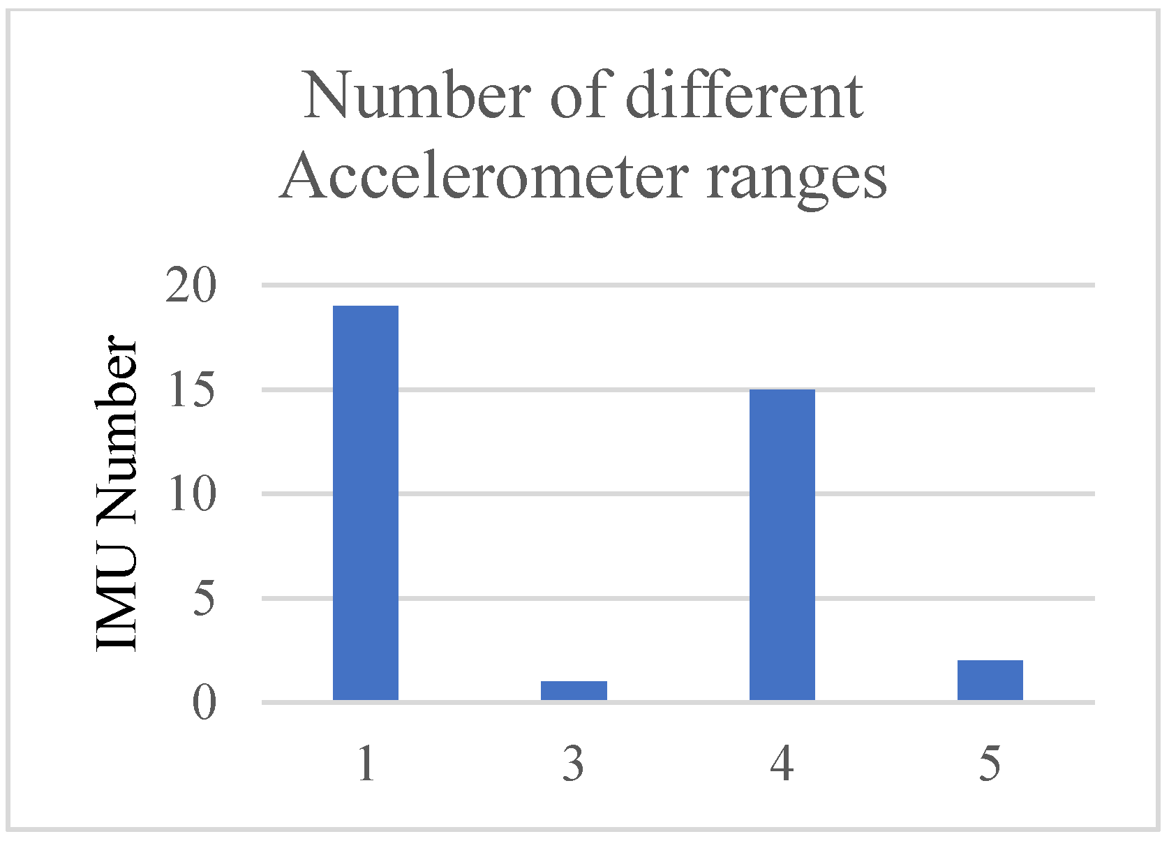
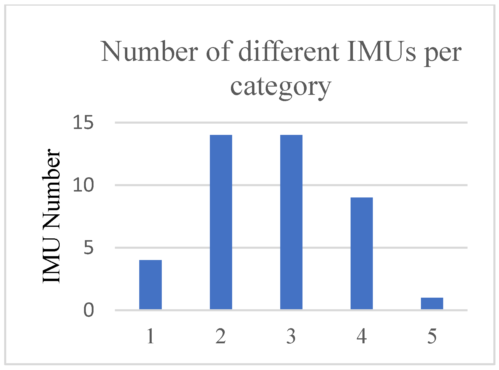
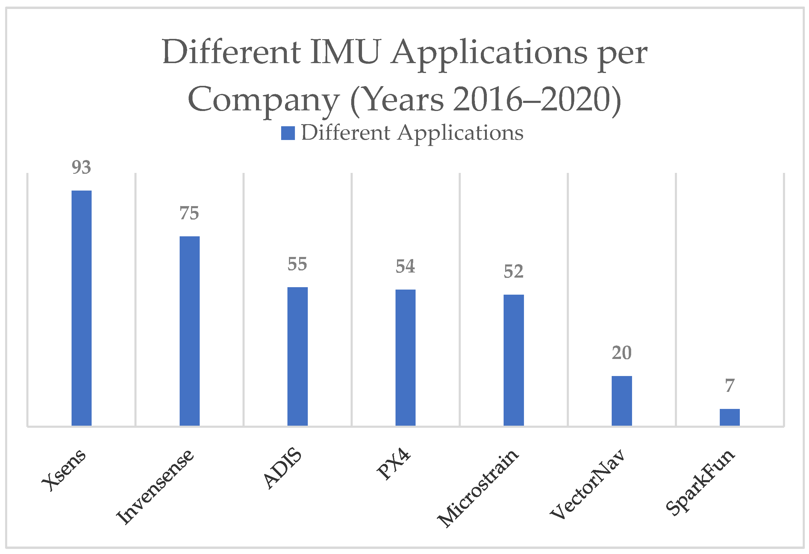
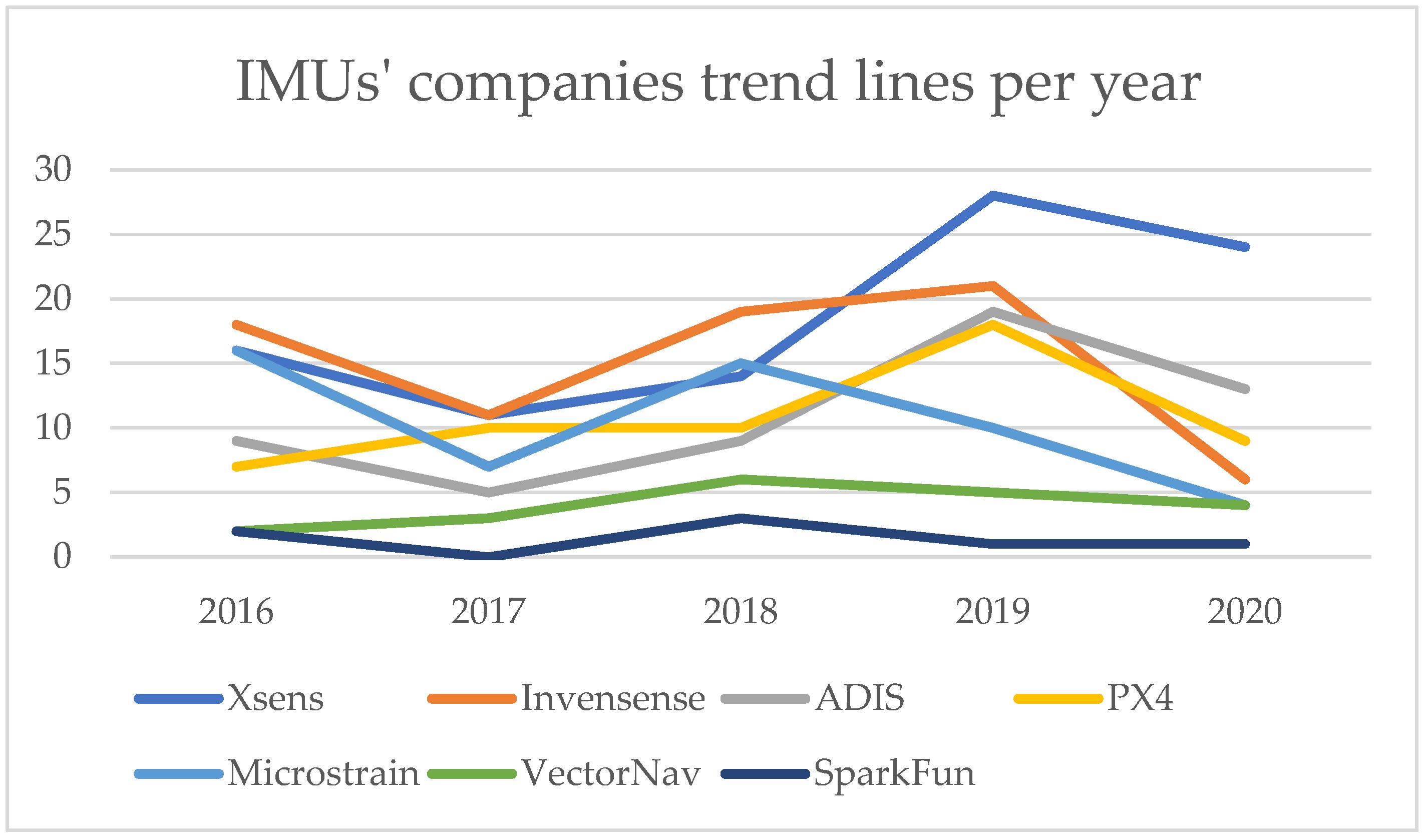
5. Usage Statistics
6. Conclusions
Author Contributions
Funding
Institutional Review Board Statement
Informed Consent Statement
Data Availability Statement
Acknowledgments
Conflicts of Interest
References
- Borenstein, J.; Everett, H.R.; Feng, L.; Wehe, D. Mobile robot positioning: Sensors and techniques. J. Robot. Syst. 1997, 14, 231–249. [Google Scholar] [CrossRef]
- Kaplan, E.; Hegarty, C. Understanding GPS: Principles and Applications; Artech House: Norwood, MA, USA, 2005. [Google Scholar]
- Lee, T.; Shin, J.; Cho, D. Position estimation for mobile robot using in-plane 3-axis IMU and active beacon. In Proceedings of the 2009 IEEE International Symposium on Industrial Electronics, Seoul, Korea, 5–8 July 2009; pp. 1956–1961. [Google Scholar]
- King, A.D. Inertial navigation-forty years of evolution. GEC Rev. 1998, 13, 140–149. [Google Scholar]
- You, Z. Space Microsystems and Micro/Nano Satellites; Butterworth-Heinemann: Beijing, China, 2017. [Google Scholar]
- Kitchenham, B. Procedures for performing systematic reviews. Keele UK Keele Univ. 2004, 33, 1–26. [Google Scholar]
- Khabsa, M.; Giles, C.L. The number of scholarly documents on the public web. PLoS ONE 2014, 9, e93949. [Google Scholar]
- Hutter, M.; Gehring, C.; Jud, D.; Lauber, A.; Bellicoso, C.D.; Tsounis, V.; Hwangbo, J.; Bodie, K.; Fankhauser, P.; Bloesch, M.; et al. Anymal-a highly mobile and dynamic quadrupedal robot. In Proceedings of the 2016 IEEE/RSJ International Conference on Intelligent Robots and Systems (IROS), Daejeon, Korea, 9–14 October 2016; pp. 38–44. [Google Scholar]
- Kim, W.; Lee, J.; Peternel, L.; Tsagarakis, N.; Ajoudani, A. Anticipatory robot assistance for the prevention of human static joint overloading in human–robot collaboration. IEEE Robot. Autom. Lett. 2017, 3, 68–75. [Google Scholar] [CrossRef]
- Dubé, R.; Gawel, A.; Sommer, H.; Nieto, J.; Siegwart, R.; Cadena, C. An online multi-robot SLAM system for 3D LiDARs. In Proceedings of the 2017 IEEE/RSJ International Conference on Intelligent Robots and Systems (IROS), Vancouver, BC, Canada, 24–28 September 2017; pp. 1004–1011. [Google Scholar]
- Yoon, P.K.; Zihajehzadeh, S.; Kang, B.; Park, E.J. Robust biomechanical model-based 3-D indoor localization and tracking method using UWB and IMU. IEEE Sens. J. 2016, 17, 1084–1096. [Google Scholar] [CrossRef]
- Bartlett, H.L.; Goldfarb, M. A phase variable approach for IMU-based locomotion activity recognition. IEEE Trans. Biomed. Eng. 2017, 65, 1330–1338. [Google Scholar] [CrossRef]
- Dang, Q.K.; Chee, Y.; Pham, D.D.; Suh, Y.S. A virtual blind cane using a line laser-based vision system and an inertial measurement unit. Sensors 2016, 16, 95. [Google Scholar] [CrossRef] [Green Version]
- Meghdari, A.; Alemi, M.; Zakipour, M.; Kashanian, S.A. Design and realization of a sign language educational humanoid robot. J. Intell. Robot. Syst. 2019, 95, 3–17. [Google Scholar] [CrossRef]
- Zhang, W.; Li, X.; Wei, D.; Ji, X.; Yuan, H. A foot-mounted pdr system based on imu/ekf+ hmm+ zupt+ zaru+ hdr+ compass algorithm. In Proceedings of the 2017 International conference on indoor positioning and indoor navigation (IPIN), Sapporo, Japan, 18–21 September 2017; pp. 1–5. [Google Scholar]
- Li, B.; Ushiroda, K.; Yang, L.; Song, Q.; Xiao, J. Wall-climbing robot for non-destructive evaluation using impact-echo and metric learning SVM. Int. J. Intell. Robot. Appl. 2017, 1, 255–270. [Google Scholar] [CrossRef]
- Wu, J.; Sun, L.; Jafari, R. A wearable system for recognizing American sign-language in real-time using IMU and surface EMG sensors. IEEE J. Biomed. Health Inform. 2016, 20, 1281–1290. [Google Scholar] [CrossRef] [PubMed]
- Park, S.; Her, J.; Kim, J.; Lee, D. Design, modeling and control of omni-directional aerial robot. In Proceedings of the 2016 IEEE/RSJ International Conference on Intelligent Robots and Systems (IROS), Daejeon, Korea, 9–14 October 2016; pp. 1570–1575. [Google Scholar]
- Alakshendra, V.; Chiddarwar, S.S. Adaptive robust control of Mecanum-wheeled mobile robot with uncertainties. Nonlinear Dyn. 2017, 87, 2147–2169. [Google Scholar] [CrossRef]
- Liu, R.; Yuen, C.; Do, T.; Jiao, D.; Liu, X.; Tan, U. Cooperative relative positioning of mobile users by fusing IMU inertial and UWB ranging information. In Proceedings of the 2017 IEEE International Conference on Robotics and Automation (ICRA), Singapore, 29 May–3 June 2017; pp. 5623–5629. [Google Scholar]
- Goldberg, B.; Zufferey, R.; Doshi, N.; Helbling, E.F.; Whittredge, G.; Kovac, M.; Wood, R.J. Power and control autonomy for high-speed locomotion with an insect-scale legged robot. IEEE Robot. Autom. Lett. 2018, 3, 987–993. [Google Scholar] [CrossRef]
- Ando, H.; Ambe, Y.; Ishii, A.; Konyo, M.; Tadakuma, K.; Maruyama, S.; Tadokoro, S. Aerial hose type robot by water jet for fire fighting. IEEE Robot. Autom. Lett. 2018, 3, 1128–1135. [Google Scholar] [CrossRef]
- Alcaide, J.O.; Pearson, L.; Rentschler, M.E. Design, modeling and control of a SMA-actuated biomimetic robot with novel functional skin. In Proceedings of the 2017 IEEE International Conference on Robotics and Automation (ICRA), Singapore, 29 May–3 June 2017; pp. 4338–4345. [Google Scholar]
- Moore, T.; Stouch, D. A generalized extended kalman filter implementation for the robot operating system. In Intelligent Autonomous Systems 13; Springer: Berlin/Heidelberg, Germany, 2016; pp. 335–348. [Google Scholar]
- Gregory, J.; Fink, J.; Stump, E.; Twigg, J.; Rogers, J.; Baran, D.; Fung, N.; Young, S. Application of multi-robot systems to disaster-relief scenarios with limited communication. In Field and Service Robotics; Springer: Berlin/Heidelberg, Germany, 2016; pp. 639–653. [Google Scholar]
- Bjelonic, M.; Kottege, N.; Beckerle, P. Proprioceptive control of an over-actuated hexapod robot in unstructured terrain. In Proceedings of the 2016 IEEE/RSJ International Conference on Intelligent Robots and Systems (IROS), Daejeon, Korea, 9–14 October 2016; pp. 2042–2049. [Google Scholar]
- Mangelson, J.G.; Dominic, D.; Eustice, R.M.; Vasudevan, R. Pairwise consistent measurement set maximization for robust multi-robot map merging. In Proceedings of the 2018 IEEE International Conference on Robotics and Automation (ICRA), Brisbane, Australia, 21–25 May 2018; pp. 2916–2923. [Google Scholar]
- Song, Y.; Nuske, S.; Scherer, S. A multi-sensor fusion MAV state estimation from long-range stereo, IMU, GPS and barometric sensors. Sensors 2017, 17, 11. [Google Scholar] [CrossRef]
- Bjelonic, M.; Kottege, N.; Homberger, T.; Borges, P.; Beckerle, P.; Chli, M. Weaver: Hexapod robot for autonomous navigation on unstructured terrain. J. Field Robot. 2018, 35, 1063–1079. [Google Scholar] [CrossRef]
- Wang, W.; Mateos, L.A.; Park, S.; Leoni, P.; Gheneti, B.; Duarte, F.; Ratti, C.; Rus, D. Design, modeling, and nonlinear model predictive tracking control of a novel autonomous surface vehicle. In Proceedings of the 2018 IEEE International Conference on Robotics and Automation (ICRA), Brisbane, Australia, 21–25 May 2018; pp. 6189–6196. [Google Scholar]
- Schwarz, M.; Rodehutskors, T.; Droeschel, D.; Beul, M.; Schreiber, M.; Araslanov, N.; Ivanov, I.; Lenz, C.; Razlaw, J.; Schüller, S.; et al. NimbRo Rescue: Solving disaster-response tasks with the mobile manipulation robot Momaro. J. Field Robot. 2017, 34, 400–425. [Google Scholar] [CrossRef] [Green Version]
- Özaslan, T.; Loianno, G.; Keller, J.; Taylor, C.J.; Kumar, V.; Wozencraft, J.M.; Hood, T. Autonomous navigation and mapping for inspection of penstocks and tunnels with MAVs. IEEE Robot. Autom. Lett. 2017, 2, 1740–1747. [Google Scholar] [CrossRef]
- Sampedro, C.; Rodriguez-Ramos, A.; Bavle, H.; Carrio, A.; de la Puente, P.; Campoy, P. A fully-autonomous aerial robot for search and rescue applications in indoor environments using learning-based techniques. J. Intell. Robot. Syst. 2019, 95, 601–627. [Google Scholar] [CrossRef]
- Schwarz, M.; Rodehutskors, T.; Schreiber, M.; Behnke, S. Hybrid driving-stepping locomotion with the wheeled-legged robot Momaro. In Proceedings of the 2016 IEEE International Conference on Robotics and Automation (ICRA), Stockholm, Sweden, 16–21 May 2016; pp. 5589–5595. [Google Scholar]
- Do, H.M.; Pham, M.; Sheng, W.; Yang, D.; Liu, M. RiSH: A robot-integrated smart home for elderly care. Robot. Auton. Syst. 2018, 101, 74–92. [Google Scholar] [CrossRef]
- Ding, Y.; Galiana, I.; Siviy, C.; Panizzolo, F.A.; Walsh, C. IMU-based iterative control for hip extension assistance with a soft exosuit. In Proceedings of the 2016 IEEE International Conference on Robotics and Automation (ICRA), Stockholm, Sweden, 16–21 May 2016; pp. 3501–3508. [Google Scholar]
- Gong, Y.; Hartley, R.; Da, X.; Hereid, A.; Harib, O.; Huang, J.K.; Grizzle, J. Feedback control of a cassie bipedal robot: Walking, standing, and riding a segway. In Proceedings of the 2019 American Control Conference (ACC), Philadelphia, PA, USA, 10–12 July 2019; pp. 4559–4566. [Google Scholar]
- Klamt, T.; Rodriguez, D.; Schwarz, M.; Lenz, C.; Pavlichenko, D.; Droeschel, D.; Behnke, S. Supervised autonomous locomotion and manipulation for disaster response with a centaur-like robot. In Proceedings of the 2018 IEEE/RSJ International Conference on Intelligent Robots and Systems (IROS), Madrid, Spain, 1–5 October 2018; pp. 1–8. [Google Scholar]
- Kundu, A.S.; Mazumder, O.; Lenka, P.K.; Bhaumik, S. Hand gesture recognition based omnidirectional wheelchair control using IMU and EMG sensors. J. Intell. Robot. Syst. 2018, 91, 529–541. [Google Scholar] [CrossRef]
- Santos, F.N.D.; Sobreira, H.; Campos, D.; Morais, R.; Moreira, A.P.; Contente, O. Towards a reliable robot for steep slope vineyards monitoring. J. Intell. Robot. Syst. 2016, 83, 429–444. [Google Scholar] [CrossRef]
- Parrott, C.; Dodd, T.J.; Groß, R. HyMod: A 3-DOF hybrid mobile and self-reconfigurable modular robot and its extensions. In Distributed Autonomous Robotic Systems; Springer: Berlin/Heidelberg, Germany, 2018; pp. 401–414. [Google Scholar]
- Li, Y.; Guo, S.; Wang, Y. Design and characteristics evaluation of a novel spherical underwater robot. Robot. Auton. Syst. 2017, 94, 61–74. [Google Scholar] [CrossRef]
- Koksal, N.; Jalalmaab, M.; Fidan, B. Adaptive linear quadratic attitude tracking control of a quadrotor UAV based on IMU sensor data fusion. Sensors 2019, 19, 46. [Google Scholar] [CrossRef] [PubMed] [Green Version]
- Donthu, N.; Gustafsson, A. Effects of COVID-19 on business and research. J. Bus. Res. 2020, 117, 284–289. [Google Scholar] [CrossRef] [PubMed]

Publisher’s Note: MDPI stays neutral with regard to jurisdictional claims in published maps and institutional affiliations. |
© 2022 by the authors. Licensee MDPI, Basel, Switzerland. This article is an open access article distributed under the terms and conditions of the Creative Commons Attribution (CC BY) license (https://creativecommons.org/licenses/by/4.0/).
Share and Cite
Samatas, G.G.; Pachidis, T.P. Inertial Measurement Units (IMUs) in Mobile Robots over the Last Five Years: A Review. Designs 2022, 6, 17. https://doi.org/10.3390/designs6010017
Samatas GG, Pachidis TP. Inertial Measurement Units (IMUs) in Mobile Robots over the Last Five Years: A Review. Designs. 2022; 6(1):17. https://doi.org/10.3390/designs6010017
Chicago/Turabian StyleSamatas, Gerasimos G., and Theodore P. Pachidis. 2022. "Inertial Measurement Units (IMUs) in Mobile Robots over the Last Five Years: A Review" Designs 6, no. 1: 17. https://doi.org/10.3390/designs6010017
APA StyleSamatas, G. G., & Pachidis, T. P. (2022). Inertial Measurement Units (IMUs) in Mobile Robots over the Last Five Years: A Review. Designs, 6(1), 17. https://doi.org/10.3390/designs6010017