Abstract
A crossed compound parabolic concentrator (CCPC) is a non-imaging concentrator which is a modified form of a circular 3D compound parabolic concentrator (CPC) obtained by orthogonal intersection of two 2D CPCs that have an optical efficiency in line with that of 3D CPC. The present work is about the design and fabrication of a new generation of solar concentrator: the hybrid photovoltaic (PV)/thermal absorptive/reflective CCPC module. The module has a 4× CCPC structure truncated to have a concentration of 3.6× with a half acceptance angle of 30°. Furthermore, an experimental rig was also fabricated to test the performance of the module and its feasibility in real applications such as building-integrated photovoltaic (BIPV). 3D printing and Computer Numerical Control (CNC) milling technologies were utilized to manufacture the absorber and reflective parts of the module.
1. Introduction
A great concern that the world faces now is the rising global temperature and subsequent phenomena of global warming. Even though it is recognized that there are natural causes for climate change, it is widely accepted by scientists and climatologists that human activity is the number-one cause for the global warming. The expelling of greenhouse gases as a part of human activities has added to this cause. As of 2010, a quarter of total global greenhouse emissions are contributed by electricity and the heat production sector [1]. Solar energy technologies such as photovoltaic (PV) and thermal have the capability to reduce greenhouse gas emissions. Considering the total energy life cycle of renewable energy sources such as PV and wind energy, the emissions rate per energy unit is considerably less than that from fossil fuels and even nuclear power [2].
The feasibility of opting for concentrating PV (CPV) over conventional flat PV panels depends on the economic advantage it can offer. The sheer price drop of flat PV panels day by day certainly makes CPV less attractive. However, CPV possesses some crucial advantages such as better electrical conversion efficiency, ease of recycling and more energy production per area thereby decreasing the cost [3,4]. Concentrating solar collectors are broadly of two different types which are imaging and non-imaging [5]. Compound parabolic concentrators (CPC) are a popular type of non-imaging solar collector with wide acceptance angles. The word compound in CPC signifies that they are comprised of 2 parabolic mirrors which are placed symmetrically to each other. The focal point of one parabolic mirror lies on the other parabolic mirror. These types of low cost non-imaging optical material replace the high-cost material solar PV cells, thus increasing the efficiency of the solar system without significant increase in cost [6].
Further studies on the 2D CPCs have paved the way for the introduction of 3D CPC with improved geometrical concentration ratio. 3D CPCs are achieved by revolving 2D CPCs along their normal axis. Nevertheless, there is an inherent limitation with the circular entry and exit apertures. As an advancement to solve these issues, 3D CPC was modified to have an accepting aperture shaped in a hexagon. Even though this step increased the packaging factor of the arrangement, there was a loss in geometrical concentration ratio due to its change in shape. Furthermore, the exit aperture remained circular [7].
The limitations of 3D CPC with decreased geometrical concentration ratio due to shape shift from circular to hexagonal entry aperture and the circular exit aperture can be solved by providing a square entry and exit aperture area. CCPC, which is a modified form of circular 3D CPC, has square entry and exit apertures. This is obtained by perpendicular intersection of two 2D CPC troughs and has an optical efficiency that is in line with that of 3D CPC [7].
Figure 1 demonstrates the optical efficiency of the CCPC with respect to incident angle. It can be observed from the ray trace simulation conducted by Sellami and Mallick that the CCPC collects almost all the incidence rays within the range of ±30°. Further angles beyond that shows a steep decrease in the optical efficiency. It should be noted that beyond 27°, the diagonal plane produces higher efficiencies. Apart from having optical efficiency in alignment to that of circular 3D CPC, the square inlet and exit apertures help to increase the area of collected solar radiation when multiple CCPCs are grouped as an array. It should also be noted that the solar cells can be used optimally when cut into a square shape rather than a circular shape [7].
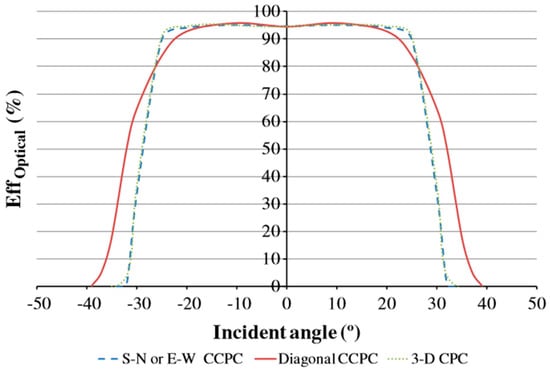
Figure 1.
Variation of the optical efficiency as a function of the incidence angle of the incoming rays. Reproduced with permission from [7], Elsevier, 2013.
Meng et al. have proposed a novel CCPC model that retains its full height and can function both as a CPV and thermal collector at the same time [8]. The novelty in their study is in converting a CCPC to a multi surface with an absorptive and reflective surface. Usually the truncated part in a CCPC is eliminated with little sacrifice to the geometric concentration ratio and optical efficiency [9]. It is now replaced by an absorbent surface to collect the radiation from the sun. In their research, they have extensively studied the thermal and optical efficiencies of the A/R CCPC module by simulation using APEX optics add-in software for SOLIDWORKS (Dassault Systèmes, Vélizy-Villacoublay, France). The total optical efficiency of the module is depicted in Figure 2. The simulation was carried out on different concentration ratios ranging from 3.6× to 4× by varying the extent of truncation. They have concluded that the 3.6× CCPC have provided the highest efficiency in case of optical efficiency alone while the 3.6×/4× A/R CCPC have higher total efficiency including the thermal contributions at all incident angles. In Figure 2, the dip in curves around incident angles 30° to 50° occurs at the transition of energy production from PV to thermal absorbent component. Beyond 30°, the PV cell does not receive solar radiation and the optical efficiency drops. Furthermore, at around 35°, the radiation reflects within the module and falls on absorber component and hence total optical efficiency increases. As an initial step towards validating the findings from simulation, they have built a simple setup with bare surfaces without any water circulation through the system and the results were promising. The result pointed that the addition of an absorptive surface can supposedly increase the wall temperatures and enhances the performance of lower solar concentrators [8].
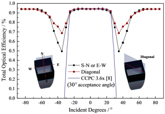
Figure 2.
Total optical efficiency of 3.6×/4× A/R CCPC under different incident angles. Reproduced from [8], Elsevier, 2016.
The A/R CCPC module presented by Meng et al. can be integrated in a hybrid PV/T system [8]. Hybrid PV/T solar collectors were first proposed in 1978 and were tested and developed over the years with outstanding analysis laid out in studies such as [5,8,10,11]. The scope of these works varies from indoor laboratory research about new concepts to practical applications. By the addition of a concentrator, which is the reflector part in this case, there is a need to address the heat generated on the PV cell itself. While it is evident that the solar cell can drop efficiency with increase in cell temperature, the PV/T hybrid system has the added benefit of removing the cell temperature [12].
The optical flux distribution in a CCPC at the exit aperture varies from the entry aperture. The study by Sellami and Mallick shows that flux distribution at the exit aperture is dependent on the solar ray incident angle [7]. At some areas, the energy at exit aperture can reach up to 50 times that of incident rays. In short, the assumption normally considered regarding the flux distribution and temperature along the cell being uniform is not true. This uneven distribution of temperature and energy can adversely affect the performance of the cell. Thus, the thermal management of the cell is of high importance. The presence of local hotspot or non-uniform heat distribution can decrease the efficiency of the panel [13]. This adverse effect of the non-uniform temperature distribution is for series connected PV panels. The presence of local hotspots makes the current drop at that panel and the entire series will be restricted by that. This phenomenon is called “current matching problem” and can be solved by keeping temperature across each series connection uniform. Apart from the drop-in efficiency, the cell can undergo thermal fatigue and will be subjected to irreversible damage [14]. Studies show the relation between cell operating temperature and the efficiency for most of the PV cell with a base temperature of 25 °C, with each increase in degree an average of 0.45% of efficiency is depleted [15]. These studies show that the thermal management of PV operating temperature is a key factor in obtaining a reliable and efficient system.
The relevance of such A/R CCPC module is when it is applied to building-integrated photovoltaics (BIPV). BIPVs are gaining huge interest in situations where energy-conscious design techniques are employed. It can provide a dual function of providing outer building skin and as an energy generator. The integration of PV will ultimately reduce the incremental cost of PV due to the replacement of conventional building materials, thus the life cycle cost is also improved [16]. The A/R CCPC can be combined into an array of such similar modules connected in parallel or series according to the requirements. Even though the temperature rise is not of a significant amount passing through the absorber, it can be stored for future use. Furthermore, with introducing phase changing material, the duration of supply of warm water can be enhanced. Each A/R CCPC module can be connected to make a large array covering a significant area [8].
The present work is about fabrication of A/R CCPC module proposed and introduced theoretically by Meng et al. [8]. The fabricated module has a 4×CCPC structure truncated to have a concentration of 3.6× with a half acceptance angle of 30°. These specifications were selected since it has superior performance as a static solar concentrator [6,7]. In addition, the work also includes installing a water-cooled heat exchanger to the back of the solar cell and installing pipes through the A/R CCPC absorber walls. More comprehensive explanation of the fabrication process and experimental rig is explained in the following section.
2. Fabrication of Hybrid PV/T A/R CCPC Module
Meng et al. proposed the dual absorptive and reflective surfaces CCPC, which served as the base for fabrication of the module in this paper [8]. Their depiction of the module is shown in Figure 3 with the black top part serving as absorbing surface and bottom part serving as reflector. Further in their study they also explained about the benefits of integrating A/R CCPC modules into a hybrid PV/T system, which can supply both electricity and heat. Table 1 provides a summary of the design parameters.
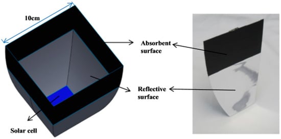
Figure 3.
Geometrical structure of A/R CCPC for modelling and testing by Meng et al. Reproduced from [8], Elsevier, 2016.

Table 1.
General design and material information about the work.
Figure 4 shows a Computer-aided Design (CAD) model of the finalized A/R CCPC module. The model consists of absorbing part with three water pipes for each wall placed over the reflective part. Based on the proposed design by Meng et al., it has an entry aperture of 0.1 × 0.1 m2 and exit aperture of 0.05 × 0.05 m2 and a combined height of 0.14 m [8]. Both parts are manufactured separately using different techniques. 3D printing was used for the manufacturing of the reflective part. Such additive manufacturing technique offers great speed and cost effectiveness for low-volume or prototyping parts. Furthermore, the manufactured product can be obtained with least post-processing requirement. Operational, material and labor costs are also greatly reduced with this technique [17].
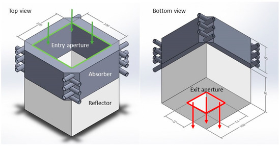
Figure 4.
Basic A/R CCPC structure with absorber on top and reflector at bottom. Entry aperture of 0.1 × 0.1 m2 and exit aperture at 0.05 × 0.05 m2.
The absorber part was made from aluminum through CNC milling technique. It is a subtractive manufacturing technique were the milling is controlled by computer rather than manually; this helps the obtaining of more precise and quickly manufactured parts [18].
The absorptive part was then coated with flat black paint with an absorptivity of 0.95 [19]. This helped in absorbing most of the direct and reflected irradiation. On the other hand, high reflective mirror tape was installed on the inner surface of reflective part. Both are depicted in Figure 5.
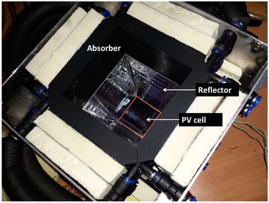
Figure 5.
Inside view of the assembled module. Note the insulations around the absorber.
2.1. Solar Cell and Heat Exchanger
A Laser Grooved Buried Contact solar cell with dimension of 0.05 × 0.05 m2 was utilized for this study. It has been previously tested under standard test conditions (STC) and exhibited an efficiency of approximately 15%. To protect the cell from degradation by direct exposure to the environment or by other climate factors, it was necessary to encapsulate the cell. Encapsulation can act as a protective layer and shock absorber above the cell [20]. Sylgard 184 Silicon Elastomer is utilized for this purpose. For examining the performance of cell and effect of cell cooling, it was necessary to attach a temperature sensor and heat exchange to the cell. For the convenience of encapsulation, attaching thermocouple and heat exchanger, an aluminum plate of 120 × 120 mm2 area and thickness of 8 mm was utilized. This provided enough area to attach the heat exchanger. A groove of 52 × 52 mm2 with a depth of 5 mm was cut into one side of the plate to accommodate the solar cell, thermocouple and encapsulant. Considering the small area of cell (0.0025 m2), only a single K-type temperature sensor was attached to back of the cell and then it was encapsulated as shown in Figure 6a.
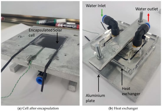
Figure 6.
From left to right (a) Cell after encapsulation of 5 mm thickness. Please note that the connections are obtained outside through channels cut into block. (b) Heat exchanger attached to the back of the aluminum plate with thermal grease in between.
As stated in literature review, the uneven distribution of energy across the PV cell can adversely affect the performance of the PV cell. It can result in efficiency loss and irreversible damages to the cell [13]. The issue with the uneven distribution of temperature over the PV cell can be solved to an extend by deploying a heat exchanger to the back of the cell.
To calculate the heat generated on the PV cell, consider a maximum irradiation of 1000 W/m2 on the concentrator with a concentration of 3.6×, resulting in a total irradiation of 3600 W/m2. The area of the cell is 0.0025 m2, which gives a total of 9 W of energy on the PV cell. Taking the electrical conversion efficiency of the cell as 15% and the remaining as heat, there will be 7.65 W of heat generated on the PV cell. The ease of availability and cost were considered while selecting the heat exchanger. A suitable heat exchanger for this purpose was micro-channeled water blocks for computer CPU cooling. They are small and can take heat loads of around 150 W [21]. The model selected for this study is Bykski Water Cooling CPU-XPR-A CPU Block from a Chinese manufacturer. It has an active heat transfer area of 85 × 85 mm2 machined out of aluminum, which is large enough to cover the entire solar cell back surface. On the other phase of the block, micro channels are cut into aluminum and the water entering the heat exchanger is forced to pass through these channels before exiting the heat exchanger. Tae et al. in their study elaborated about the flow characters and heat transfer in a similar micro-channeled heat exchanger [21]. Figure 7 represents the heat exchanger. The high-pressure connectors are connected to the heat exchanger and then attached to the aluminum block with means of thermal paste as shown in Figure 6.
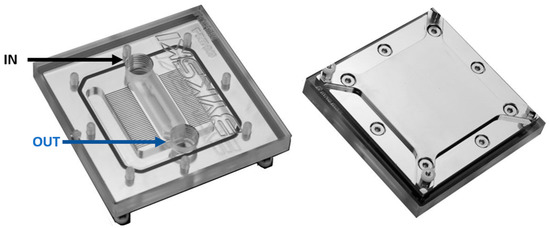
Figure 7.
Top (left) and bottom (right) view of the heat exchanger. The micro channels are visible through the acrylic cover of the heat exchanger. The area of active heat exchanger area is 85 × 85 mm2.
2.2. Flow Pipes and Insulation
To circulate water through the pipes in absorber, clear PVC tubing of 5.5 mm diameter connected with high-pressure plastic connectors is employed throughout the system. Pipe foam insulation is added to avoid thermal loss through the pipe. The pipes selected were of sufficient stiffness to avoid excess bending and jamming the passage. One end of the pressure connecters was connected to the absorber and the other ends were brought outside of the enclosure so that the flow pattern arrangement can be adjusted without disturbing rest of the module as shown in Figure 8.
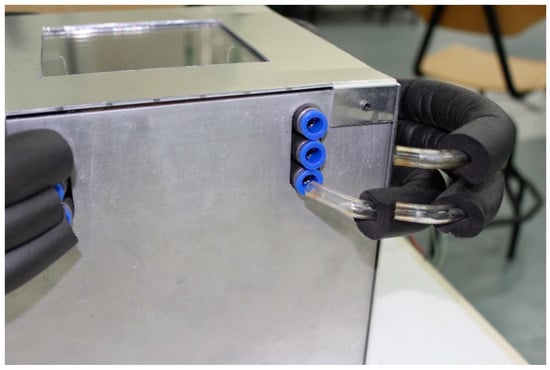
Figure 8.
A view from the side of the module. The pipes are disconnected to show the type of high-pressure connectors used. Furthermore, the pipes are insulated to avoid loss of heat. The flow pattern within the absorber can be easily varied using this setup.
The whole assembly including solar cell with heat exchanger, absorber and reflector is then insulated with foam boards and placed in an enclosure made from aluminum sheets as shown in Figure 9. The enclosure has a square hole cut into it at the top for the sun rays to enter and is covered using low iron glass of thickness 8 mm, sourced from a local manufacturer. The advantage of using this specific type of glass is that it has higher transmittivity and eliminates the green tint that a normal glass usually possesses [22]. A completely assembled module with tubing and sensors connected to respective data loggers is shown in Figure 10.
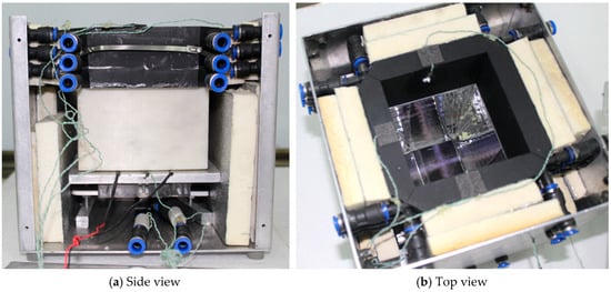
Figure 9.
(a) A view from side of the module. (b) A top view of the module before glass cover added. A thermocouple attached to the absorber wall is visible.
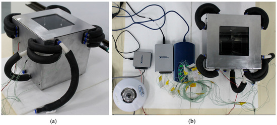
Figure 10.
(a) Completed A/R CCPC module. (b) Whole setup with measuring instruments and sensors attached.
3. Working Principle
The A/R CCPC module is placed in an area with sufficient solar rays falling on it. Depending on the incident angles of the solar rays, the PV cell, reflector and absorber surfaces receive solar rays. This can be either direct incident rays or by reflection from other surfaces within the A/R CCPC module.
Figure 11 represents the behavior of the incident rays on A/R CCPC module simulated using ray tracing software from study by Meng et al. [8]. From 0° to 30°, almost all the incident rays pass through the exit aperture of the reflector. At these angles, the performance of the PV cell will be dominant. Beyond 30°, some of the incident rays escape from the module and the PV cell gets isolated from direct incident rays. Above this angle, absorbent surface receives most of the incident rays and absorber contributes more to the total performance. At certain angles, such as 50°, the rays after three reflections fall to the back wall of the absorber. Beyond this point the insolation drops drastically and the temperature falls.
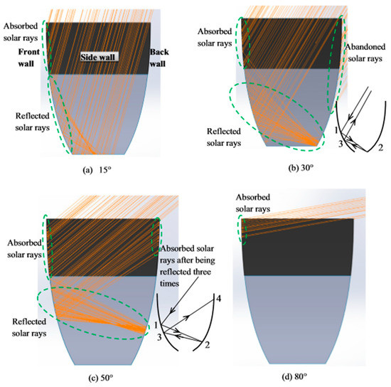
Figure 11.
Ray tracing of the module simulated by APEX software at different incident angles. Reproduced from [8], Elsevier, 2016.
A portion of the total rays’ incidents on the PV cell is converted to electricity based on cell conversion efficiency, while the remaining portion of rays’ incidents on the PV cell is converted into heat. This creates uneven heat distribution on the cell surface. This heat is then transferred to the heat exchanger through an aluminum plate on which both cell and heat exchanger are attached to either ends. Water is circulated through micro-channeled heat exchanger where it acquires the heat and then passed on to the series connected absorber on top of assembly. The incident solar rays increase the temperature of the absorber surfaces which is then passed on to water circulating through the pipes inserted into absorber. The water after circulating through the four walls of absorber will be finally collected in a storage tank. A 12 V DC centrifugal pump with a maximum flow rate of 16.5 mL/s provides the necessary pumping throughout the module. The flow rate was calibrated with respect to the input voltage to the pump. The flow pattern through the system is depicted in Figure 12.
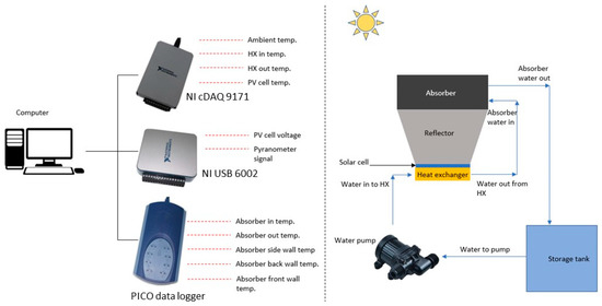
Figure 12.
Left side—Depicts the instruments utilized for acquiring their respective temperature and voltage signals. Right side—Depicts the flow path of water through the module.
The solar irradiation was measured using an Pyranometer (EKO Instruments, Den Haag, The Netherlands) (MS 402) with a sensitivity of 7.03 μV/Wm2 [23]. To measure the temperature signals, National Instruments (NI) (National Instruments Corporation, 11500 Mopac Expwy, Austin, Texas, TX, USA) and PICO (Pico Technology Limited, St Neots, England) temperature data loggers were utilized. While the NI provides more accurate readings, due to the limited analog channels available in NI cDAQ 9171, only four thermocouples, heat exchanger in and out water, ambient and cell temperatures were connected. The remaining thermocouples to measure the absorber wall temperatures were connected to a PICO temperature data logging instrument. NI USB 6002 was also used for measuring the two voltage signals from PV cell and Pyranometer. A LabView code was developed which can record the thermocouple and voltage signals at each second and saved as text file for further processing. It also provided the live wave graph for monitoring.
4. Performance of the Absorber Wall and PV Cell with Respect to Incident Angle of Solar Rays
To explore the potential and behavior of the module with respect to various solar incident angles, a test was conducted by placing the module exposing to sun aligned to S-N or E-W direction for an entire day. There was no water circulation throughout the system. The irradiation, open circuit voltage of PV cell and absorber wall temperature was observed and logged throughout the test day. Please note that the dips between incident angles of 44° to 52° occurred due to cloudiness.
Figure 13 and Figure 14 depict the relation between the measured absorbent surface temperature and open circuit voltage of PV cell with respect to the solar ray incident angles between 0° to 90°. The wall specified in the graph is the one that directly faces towards the incident solar ray direction. Please note that the A/R CCPC module is aligned towards the S-N or E-W direction. At incident angle of 11°, the insolation was at the maximum; beyond this angle the insolation decreases. However, this change in insolation is not exactly reflected in the wall temperature or in the cell voltage as shown in Figure 13 and Figure 14, respectively. It was rather observed that the wall temperature kept on increasing till incident angle of 50°. On the other hand, the open circuit voltage of PV cell drastically decreased beyond 30°. This behavior of absorber component and PV cell with respect to incident angles can be related to the ray tracing simulation of the module using APEX software conducted by Meng et al. [8].
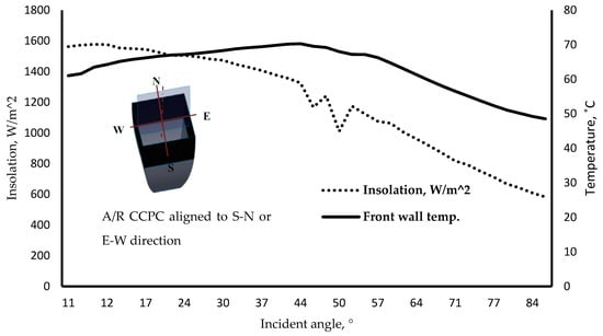
Figure 13.
Variations of absorber front wall temperature with respect to incident angles.
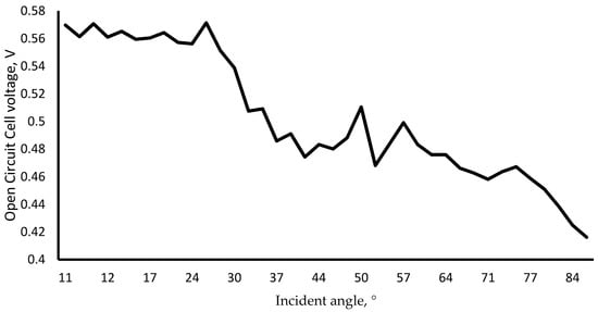
Figure 14.
Variation of cell voltage with various angles of incidence. Please note that the peak performance was a till incident angle of 30°, beyond the voltage drops drastically.
Overall, the preliminary test showed promising results and, in future, further tests can be conducted to examine the behavior and feasibility of the module for building-integrated systems for combined electricity and thermal generation.
5. Conclusions
In this study, a hybrid A/R CCPC PV/T module was fabricated. The fabricated module was put together as a compact unit with a degree of flexibility in case of varying flow patterns and mobility. The fabrication process does not include any permanent welding or similar sorts of methods which makes it easy in the future to modify or improve the system. Furthermore, an experimental rig was also developed that can be utilized to carry out different experiments. The flexibility of the rig helps in studying the performance of the hybrid A/R CCPC module in terms of varying flow rates, different orientation towards the sun, effect of solar incident angles. The arrangement of flow patterns within the absorber part can also be varied. As the next step, experiments can be carried out on the rig to determine the performance and feasibility of the module in BIPV.
Author Contributions
Conceptualization, N.S.; Methodology, N.S., M.N., and M.A.; Software, M.N. and M.A.; Validation, M.N., N.S. and M.A.; Formal Analysis, M.N., N.S. and M.A.; Investigation, M.A., M.N. and N.S.; Resources, M.N. and N.S.; Data Curation, M.A. and M.N.; Writing-Original Draft Preparation, M.A.; Writing-Review & Editing, M.N. and N.S.; Visualization, M.A. and M.N.; Supervision, N.S. and M.N.
Funding
This research received no external funding.
Conflicts of Interest
The authors declare no conflict of interest.
Nomenclature
| CPC | compound parabolic concentrator |
| CCPC | crossed compound parabolic concentrator |
| A/R CCPC | absorptive/reflective CCPC |
| BIPV | building-integrated photovoltaic |
| CPV | concentrated photovoltaic |
| PV/T | photovoltaic/thermal |
| CNC | computer numerical control |
References
- US EPA. Global Greenhouse Gas Emissions Data. 2018. Available online: https://www.epa.gov/ghgemissions/global-greenhouse-gas-emissions-data (accessed on 28 June 2018).
- Nugent, D.; Sovacool, B.K. Assessing the lifecycle greenhouse gas emissions from solar PV and wind energy: A critical meta-survey. Energy Policy 2014, 65, 229–244. [Google Scholar] [CrossRef]
- Chemisana, D. Building Integrated Concentrating Photovoltaics: A review. Renew. Sustain. Energy Rev. 2011, 15, 603–611. [Google Scholar] [CrossRef]
- Meng, X.; Xia, X.; Sun, C.; Dai, G. Optimal design of symmetrical two-stage flat reflected concentrator. Sol. Energy 2013, 93, 334–344. [Google Scholar] [CrossRef]
- Tyagi, V.; Kaushik, S.; Tyagi, S. Advancement in solar photovoltaic/thermal (PV/T) hybrid collector technology. Renew. Sustain. Energy Rev. 2012, 16, 1383–1398. [Google Scholar] [CrossRef]
- Sellami, N.; Mallick, T.; McNeil, D. Optical characterisation of 3-D static solar concentrator. Energy Convers. Manag. 2012, 64, 579–586. [Google Scholar] [CrossRef]
- Sellami, N.; Mallick, T. Optical efficiency study of PV Crossed Compound Parabolic Concentrator. Appl. Energy 2013, 102, 868–876. [Google Scholar] [CrossRef]
- Meng, X.; Sellami, N.; Knox, A.; Montecucco, A.; Siviter, J.; Mullen, P.; Ashraf, A.; Samarelli, A.; Llin, L.; Paul, D.; et al. A novel absorptive/reflective solar concentrator for heat and electricity generation: An optical and thermal analysis. Energy Convers. Manag. 2016, 114, 142–153. [Google Scholar] [CrossRef]
- Shneishil, A. Optical Design of Two Dimension Compound Parabolic Solar Thermal Concentrator. Int. J. Sci. Eng. Technol. 2017, 6, 29–34. [Google Scholar]
- Suzuki, A.; Kitamura, S. Combined Photovoltaic and Thermal Hybrid Collector. Jpn. J. Appl. Phys. 1980, 19, 79. [Google Scholar] [CrossRef]
- Riffat, S.; Cuce, E. A review on hybrid photovoltaic/thermal collectors and systems. Int. J. Low-Carbon Technol. 2011, 6, 212–241. [Google Scholar] [CrossRef]
- Bahaidarah, H.; Baloch, A.; Gandhidasan, P. Uniform cooling of photovoltaic panels: A review. Renew. Sustain. Energy Rev. 2016, 57, 1520–1544. [Google Scholar] [CrossRef]
- Li, G.; Xuan, Q.; Pei, G.; Su, Y.; Ji, J. Effect of non-uniform illumination and temperature distribution on concentrating solar cell—A review. Energy 2018, 144, 1119–1136. [Google Scholar] [CrossRef]
- Royne, A.; Dey, C.; Mills, D. Cooling of photovoltaic cells under concentrated illumination: A critical review. Sol. Energy Mater. Sol. Cells 2005, 86, 451–483. [Google Scholar] [CrossRef]
- Skoplaki, E.; Palyvos, J. On the temperature dependence of photovoltaic module electrical performance: A review of efficiency/power correlations. Sol. Energy 2009, 83, 614–624. [Google Scholar] [CrossRef]
- Wbdg.org. Building Integrated Photovoltaics (BIPV)|WBDG Whole Building Design Guide. 2017. Available online: https://www.wbdg.org/resources/building-integrated-photovoltaics-bipv (accessed on 23 August 2017).
- 3D Hubs. The Advantages of 3D Printing. 2018. Available online: https://www.3dhubs.com/knowledge-base/advantages-3d-printing (accessed on 28 June 2018).
- Cs.cmu.edu. CNC Milling—Basic Information. 2018. Available online: http://www.cs.cmu.edu/~rapidproto/students.06/ibrown/CNC%20Mill/information.html (accessed on 28 June 2018).
- Engineeringtoolbox.com. Surface—Radiation Absorptivity. 2018. Available online: https://www.engineeringtoolbox.com/radiation-surface-absorptivity-d_1805.html (accessed on 28 June 2018).
- Saur Energy International. Solar Panel Lamination: Procedure, Advantages and Future. 2018. Available online: http://www.saurenergy.com/solar-energy-articles/solar-panel-lamination-procedure-advantages-and-future (accessed on 28 June 2018).
- Choi, J.T.; Kwon, O.K.; Cha, D.A. A numerical study of the heat transfer and fluid flow of micro-channeled water block for computer CPU cooling. J. Mech. Sci. Technol. 2011, 25, 2657–2663. [Google Scholar] [CrossRef]
- Yang, J.K.; An, X.H.; Liu, Y.L.; Zhao, H.L. Analysis and Calculation of Melting Performance for the Low-iron Glass. J. Mater. Sci. Eng. 2009, 4, 034. [Google Scholar]
- Eko-eu.com. MS-402 Pyranometer|EKO Instruments. 2018. Available online: https://eko-eu.com/products/solar-energy/pyranometers/ms-402-pyranometer (accessed on 28 June 2018).
© 2018 by the authors. Licensee MDPI, Basel, Switzerland. This article is an open access article distributed under the terms and conditions of the Creative Commons Attribution (CC BY) license (http://creativecommons.org/licenses/by/4.0/).