Article

Optimization Design of Variable Speed Induction Motors for Pumping Loads

by
Makpal Zharkymbekova
1,*,
Viktor Petrushyn
2,
Kakimzhan Gali
1,
Nurgul Almuratova
1,
Juriy Plotkin
3 and
Rostyslav Yenoktaiev
3
1
Department of Electrical Power Engineering, Institute of Energy and Green Technologies, University of Power Engineering and Telecommunications Named After G. Daukeyev, Almaty 050013, Kazakhstan
2
Department of Electromechanical Engineering, Institute of Electrical Engineering and Electromechanics, Odessa Polytechnic National University, 65044 Odesa, Ukraine
3
Department of Electrical Engineering, Faculty of Cooperative Studies, Berlin School of Economics and Law, 10315 Berlin, Germany
*
Author to whom correspondence should be addressed.
Designs 2026, 10(3), 56; https://doi.org/10.3390/designs10030056
Submission received: 28 February 2026 / Revised: 8 May 2026 / Accepted: 13 May 2026 / Published: 15 May 2026

Abstract

The design of special induction motors for variable-speed drives in pumping systems is carried out using the Design of induction machines for adjustable-speed drives (DIMASDrive 2022) software, based on the motor efficiency criterion. The quality of a variable-speed drive is fully determined by an innovative criterion of equivalent costs, which takes into account not only the cost and energy efficiency of the drive, but also the costs of compensating for reactive power and distortion power, which characterize the drive’s energy and electromagnetic compatibility with the grid. The MATLAB program enables the calculation of the innovative criterion of the drive’s reduced costs. Currently, the cost component of distortion power compensation is not taken into account in the reduced cost criterion; consequently, the quality of the drive in monetary terms is determined incompletely and is underestimated. A method is proposed for calculating this component and incorporating it into the reduced cost criterion. The presented results were obtained entirely through simulations conducted using validated software. Experimental studies of the prototype will provide the final answer regarding the solution.

Graphical Abstract

1. Introduction

In recent years, electric drive systems with a wide range of smooth speed control have become increasingly popular. Energy savings are particularly significant when implementing asynchronous variable speed drives for pumps, as electric drives for pumping stations are among the most energy-intensive facilities. In this regard, there has been a widespread replacement of non-adjustable pump drives with frequency-controlled ones [1,2,3,4,5,6,7,8,9,10].
At the same time, the use of standard general-purpose motors for electric drives with variable speed is not optimal in terms of weight, size, cost and energy efficiency. It is advisable to use special variable speed induction motors (VSIM) adapted to specific operating conditions [11,12,13,14].
To do this, it is necessary to make the correct choice of a base motor (usually a standard motor), which must then be adapted. Taking into account the specifics of operation involves representing the pump unit in the form of a load characteristic, which is the dependence of the torque on the motor shaft in a given range of angular velocity changes.
An important issue is the design criteria used in the design of controlled induction motors. Along with the traditional criterion of motor efficiency, an innovative criterion of reduced costs can be used, taking into account not only the cost and energy efficiency of the drive, but also the costs of compensating for reactive power and distortion power, which characterize the energy and electromagnetic compatibility of the drive with the network [15,16,17,18,19]. It should be noted that, due to the specifics of operation, the criteria are range-based and depend on the pump operating mode [20].
Optimization design can be carried out using computer programs. MATLAB/Simulink R2023a [21,22,23,24,25,26,27] and DIMASDrive are used to simulate the drives under consideration, which incorporate various types of induction motors. The DIMASDrive program is an academic tool developed by the Department of Electrical Machines at Odessa Polytechnic University. Using the optimization procedures of the DIMASDrive program, modifications of controlled induction motors are designed, differing in various design parameters—variables within the accepted drive structure. The optimization problem is solved using the Nelder–Mead deformable polyhedron method. The complex search method is a modification of the simplex method. A distinctive feature of the method is the formation, according to a specific rule, of a set of points in an n-dimensional Euclidean space of variable parameters. A regular polyhedron, called a simplex, is constructed using these points. In the Nelder and Mead method, the simplexes lose their regularity and the polyhedra become deformed. During reflection, operations of stretching or compression are performed on them. As a result of repeatedly replacing the worst point with the point having the best value of the objective function, all points in the set are grouped in the region of the extremum, and any point from the set can be regarded as the optimal result. Frequency converters are characterized by different types and modes of control, but the most common are two-stage transistor frequency converters with autonomous voltage inverters. Research on drives with such converters was carried out using the proportional frequency control law U/f = const.
The technical prerequisites that give adapted motors an advantage over mass-produced machines include:
The ability to select the optimal ratio of non-standard voltage and frequency values for the designed motor, consistent with the nominal values of the converter, which allows for increased power within the same dimensions or reduced weight and dimensions for the same power;
The elimination of start-up performance requirements, which allows the use of an appropriate rotor slot shape that ensures minimum active resistance of the rotor winding.
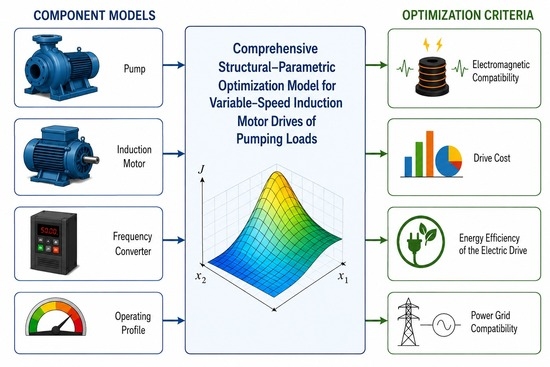
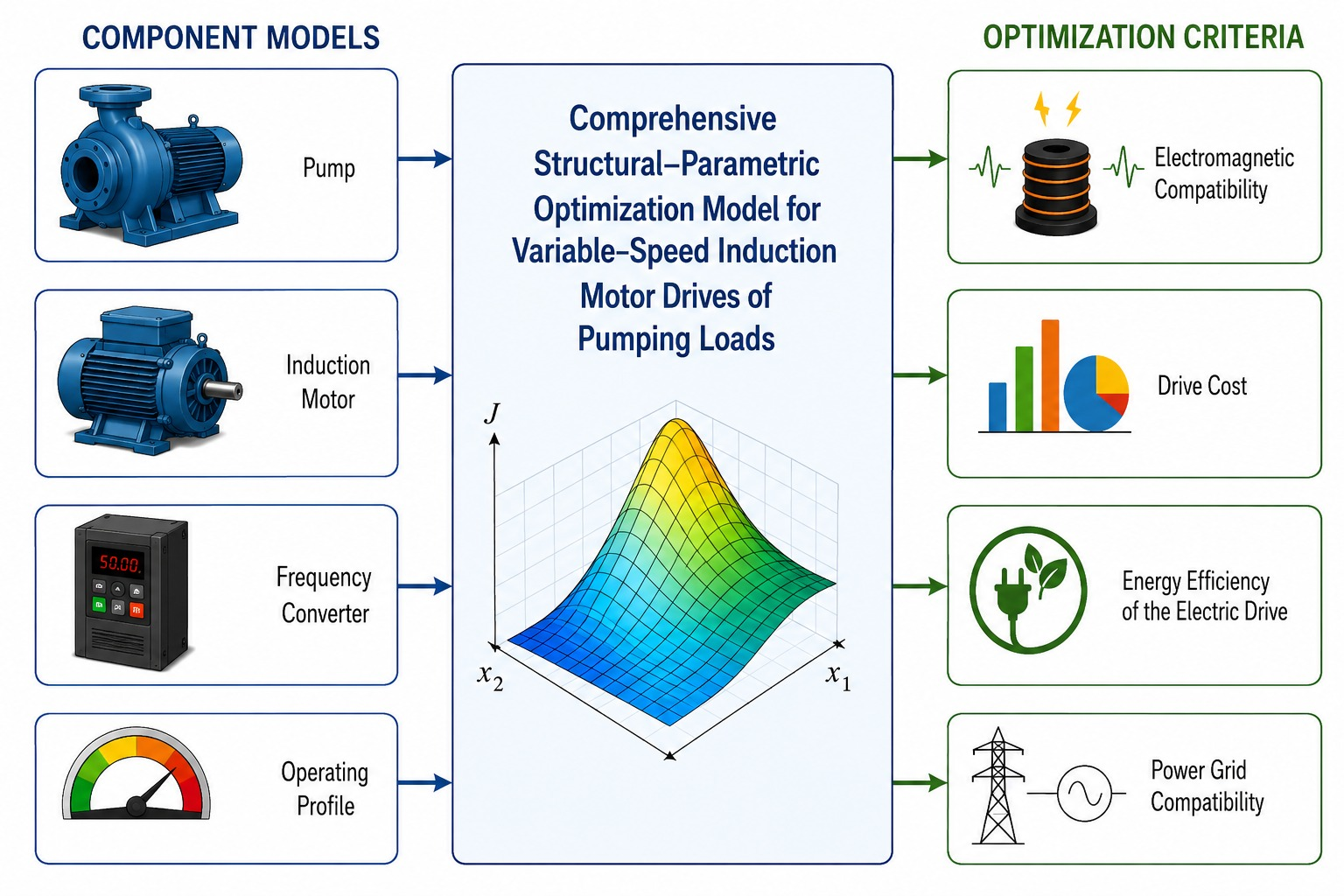
Each pump unit can be represented by a corresponding load characteristic. Using this characteristic in conjunction with the characteristics of the induction motor and the variable-frequency drive makes it possible to analyze energy performance. The DIMASDrive software’s optimization procedure designs variable-speed induction motors through structural-parametric optimization. The motor’s energy efficiency is used as the objective function. To determine the cost-based quality indicator of the electric drive, modeling is performed in MATLAB/Simulink, using an innovative criterion of reduced costs that takes into account not only the cost and energy efficiency of the drive, but also the costs of compensating for reactive power and distortion power, which characterize the drive’s energy and electromagnetic compatibility with the grid. This criterion is used to evaluate the quality of design variants for electric drives with optimized variable-speed induction motors.
The value of this criterion—specifically, the component relating to the cost of compensating for distortion—depends on the permissible THD values and is determined for a specific electric drive of a pumping unit, taking into account its operating conditions.

2. Description of the Load Characteristics of the Pumping Unit

The main characteristic of pumps is the dependence of the developed head H (m) on the productivity Q (m3/s). The values of these parameters (Figure 1), which are set depending on the corresponding rotation speeds, make it possible to form the load characteristic of the pump unit under study in a regulated drive. At the same time, for different rotation speeds, it is necessary to take into account different values of the pump efficiency.
Then P = ρ 1 · g · Q · H ɳ p u m p , where ρ 1 is the density of the pumped liquid (for water, ρ 1 = 1000   k g / m 3 ); g is the acceleration due to gravity, g = 9.81   m / s 2 ; Q is the pump capacity, m 3 / h ; H is the total head, m; ɳ p u m p is the pump efficiency.
On the other hand, P = M · π · n 30 , which, given known rotation speeds, makes it possible to calculate the load moments on the motor shaft. This makes it possible to move from the dependencies of the changes in parameters H and Q during regulation to the construction of the load characteristic n(M) (Table 1).
Regulation must ensure that output is reduced from the maximum value Q m a x to the minimum value Q m i n . According to the specified output range Q m a x =   393   m 3 / h ,   Q m i n = 39.43   m 3 / h , the pump speed variation range is n m a x = 1440   r p m ,   n m i n = 148   r p m . In this case, the head values will be as follows: Hmax = 18.1 m, Hmin = 1.35 m.
The design of motors in variable speed drive systems is carried out by considering the drive and load together. For this purpose, a mathematical model of the load must be used in the comprehensive mathematical model of the drive. The mechanical load on the motor shaft is a function of the change in resistance torque with respect to the angular frequency of rotation and is generally described by the following expression.
M ( ω ) = M 0 + k · ω i ;
where M 0 —is the initial moment, N · m , k —is the proportionality coefficient, ω is the angular frequency of shaft rotation, s−1, i —is the index determining the nature of the load change. The value of the load torque at a given point depends on three parameters: M 0 ,   k , i . They are selected so that the actual load dependence of the pump unit can be described by a mathematical relationship.
For centrifugal pump loads, i = ( 2 3 ) . Fans, blowers, centrifuges, and smoke exhausters also have similar characteristics. We assume that the pump load torque is characterized by a quadratic dependence on the rotational frequency n with some initial torque M 0 .
M = M 0 + k · n 2 .
To determine the values of M 0 and k of the load characteristic in the above form, we solve the system of equations:
n 1 2 · x 1 + x 2 = M 1 n 2 2 · x 1 + x 2 = M 2 ;
where x 1 = k and x 2 = M 0 . We use the extreme load points of the control range n 1 = 148   r p m ,   M 1 = 11.5   N · m ,   n 2 = 1440   r p m ,   M 2 = 150   N · m . When solving the system, the proportionality coefficient k and the initial torque M 0 are determined. The system in matrix notation has the following form:
k M 0 = n 1 2 1 n 2 2 1 1 · M 1 M 2 .
The system solution gives the following results: k = 0.0656 · 10 3 ,   M 0 = 10.1   N · m . That is, the dependence of the load torque on the number of pump revolutions can be represented as:
M = 10.1 + 0.0656 · 10 3 · n 2 .
By adjusting the parameters M 0 , k , i , in this way, the best representation of the pump load characteristics is achieved.

3. Simulation of a Frequency-Controlled Electric Drive Using the DIMASDrive Program

The DIMASDrive program allows you to simulate a frequency-controlled asynchronous electric (FCAED) drive using models of its components. Drives with identical frequency converters operating on the same pump load are considered, differing in the use of a 4A180S4 series motor and two of its modifications.
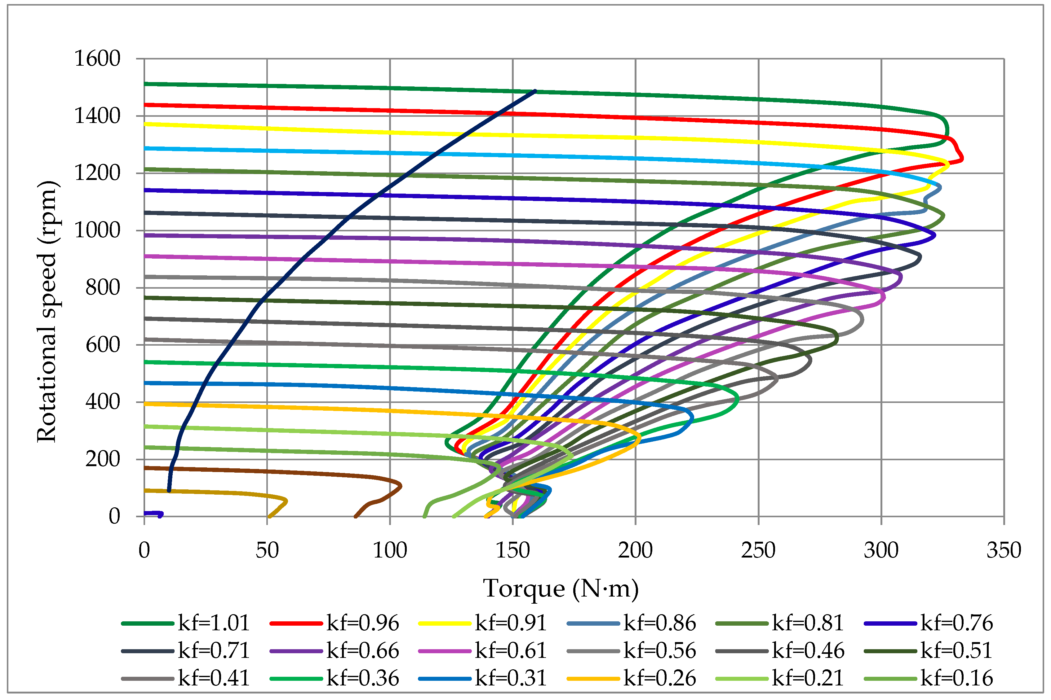
For each drive variant, it is possible to construct a given family of mechanical characteristics ( K F = f / f n where f n = 50   H z ) with the load characteristics of the pump unit superimposed on them. Figure 2 below shows the characteristics for the drive variant with a 4A180S4 series motor.
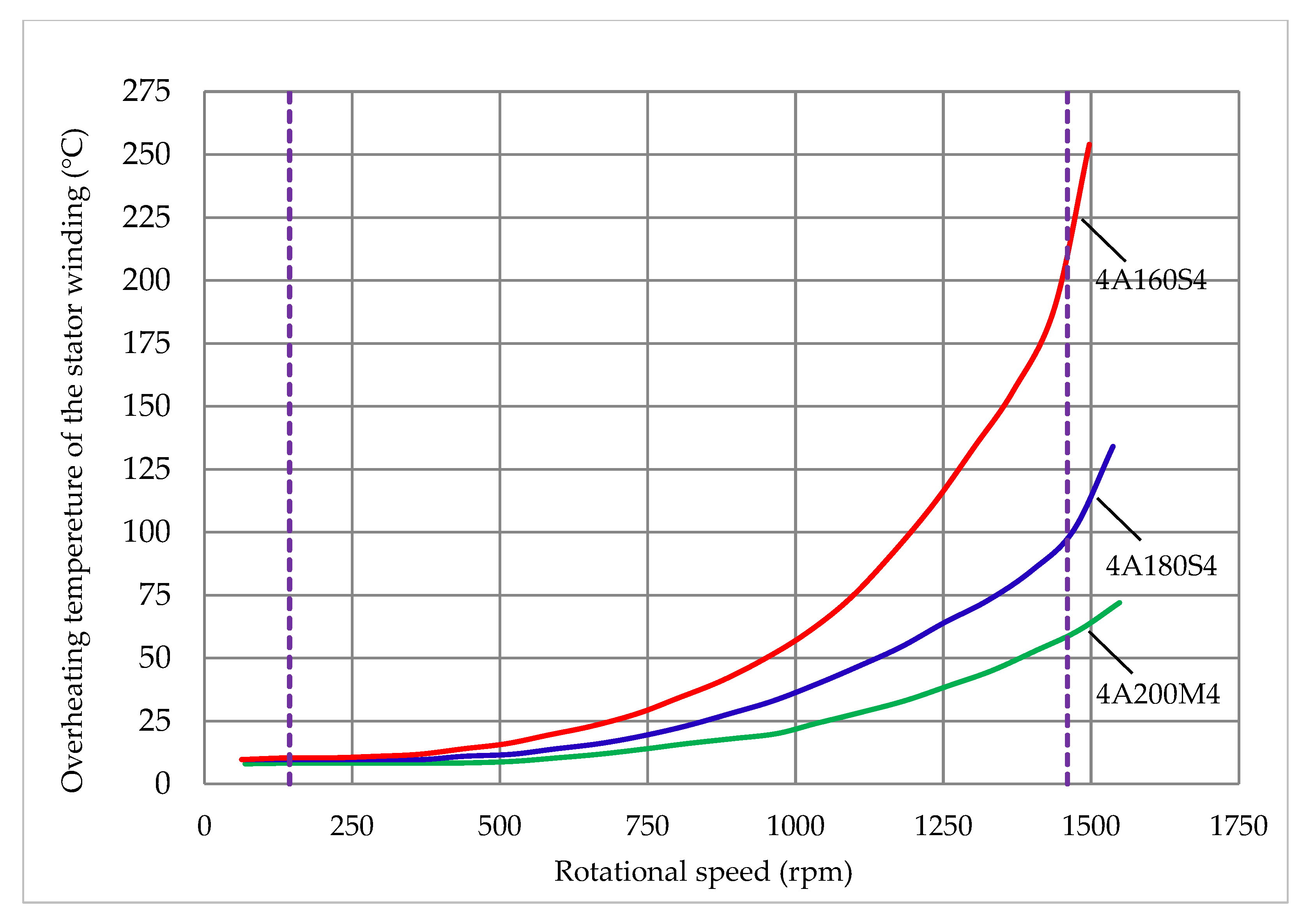
Using the DIMASDrive program, the selection of a base engine for a specific project is performed based on an analysis of the thermal state (steady-state values of the temperature of the stator winding slot, as the most thermally stressed structural part of the engine) of several series engines. Figure 3 shows the temperature characteristics of three engines for which a thermal analysis was performed.
Judging by the thermal characteristics, the 4A180S4 motor (power 22 kW) is a suitable base motor, which will be further adapted to the specific conditions as part of a frequency-controlled pump drive. The 4A160S4 motor (power 15 kW) is overloaded at the maximum point of the control range and has a significant temperature in the stator winding slot. At the same time, the 4A200M4 motor (power 37 kW) is underloaded.

4. Optimized Design in the DIMASDrive Environment Based on the Motor Efficiency Criterion

To design effective adjustable induction motors, it is necessary to use design criteria related to manufacturing and operating costs and to consider design constraints, taking into account various design tasks. At the same time, according to the principle of a systematic approach, it is necessary to consider converters, motors and loads together, and in many cases, matching gearboxes and transformers. Therefore, the main feature in the development of controlled induction motors is the need to use a comprehensive MM of the entire controlled automated electric drive system in the design calculation system, rather than just a motor model, as is done in the design of general industrial induction motors. Thus, design and FCAED MM must have a certain degree of flexibility in order to take into account the components introduced into the drive structure, as well as changes in the design parameters of the motor. Modern optimization design of FCAED machines is well developed and generalized, but it is not focused on controlled induction motors. Mathematical and software improvements are needed to effectively solve the design problems of special controlled induction motors. Optimization design of controlled induction motors can be performed using a range criterion—efficiency. In this case, the energy efficiency of the motor can be considered as average range efficiency:
ɳ c d = 1 n 2 n 1 · n 1 n 2 ɳ ( n i ) d n .
Two modifications of the basic 4A180S4 motor are offered. The first modification is achieved by replacing thin-gauge cold-rolled isotropic electrical steel grade 2211 with steel grade 2411. The specific losses of grade 2211 steel are p = 2.2   W / k g , and those of grade 2411 steel are p = 1.3   W / k g . This modification also involves replacing the shortened stator winding with a diametrical winding. This relates to structural optimization. In the second modification, the parameters of the stator winding (number of stator winding turns w1, cross-sectional area of the effective stator winding conductor q e f f , diameter of the insulated stator conductor d i n s ). The number of variable parameters also includes the length of the machine core L, the geometric parameters of the stator tooth zone (stator slot height H1 and stator slot width GP) and the rotor (distance between the centers of circles A2, diameter of the larger circle D2, and diameter of the smaller circle D2).
Table 2 shows the values of the variable parameters obtained as a result of optimization design using the DIMASDrive program based on the criterion of average motor efficiency.
The number and range of the variable parameters can be adjusted, resulting in different modifications of the base motor.
Table 3 shows the average efficiency values for the standard motor and the two modifications considered. The pump speed ranges from n m i n = 148   r p m   t o   n m a x = 1440   r p m .
In some cases, the engine efficiency criterion must be calculated taking into account the operating time at each specified rotation frequency within the control range. Then a temporary load operation diagram is set—a tachogram. In this case, the calculation of the duration of engine operation at each specified point of the control range according to the following expression [15]:
ɳ d t = i ( ɳ ( ɳ i ) · t n i ) i t n i ;
where t n i —the operating time of the machine under investigation at a rotational speed of n i , i —the step number on the tachogram. If the drive operates with a tachogram of 1 h—200 rpm; 1 h—600 rpm; 1 h—1400 rpm, then the range criteria for efficiency are presented in Table 4.
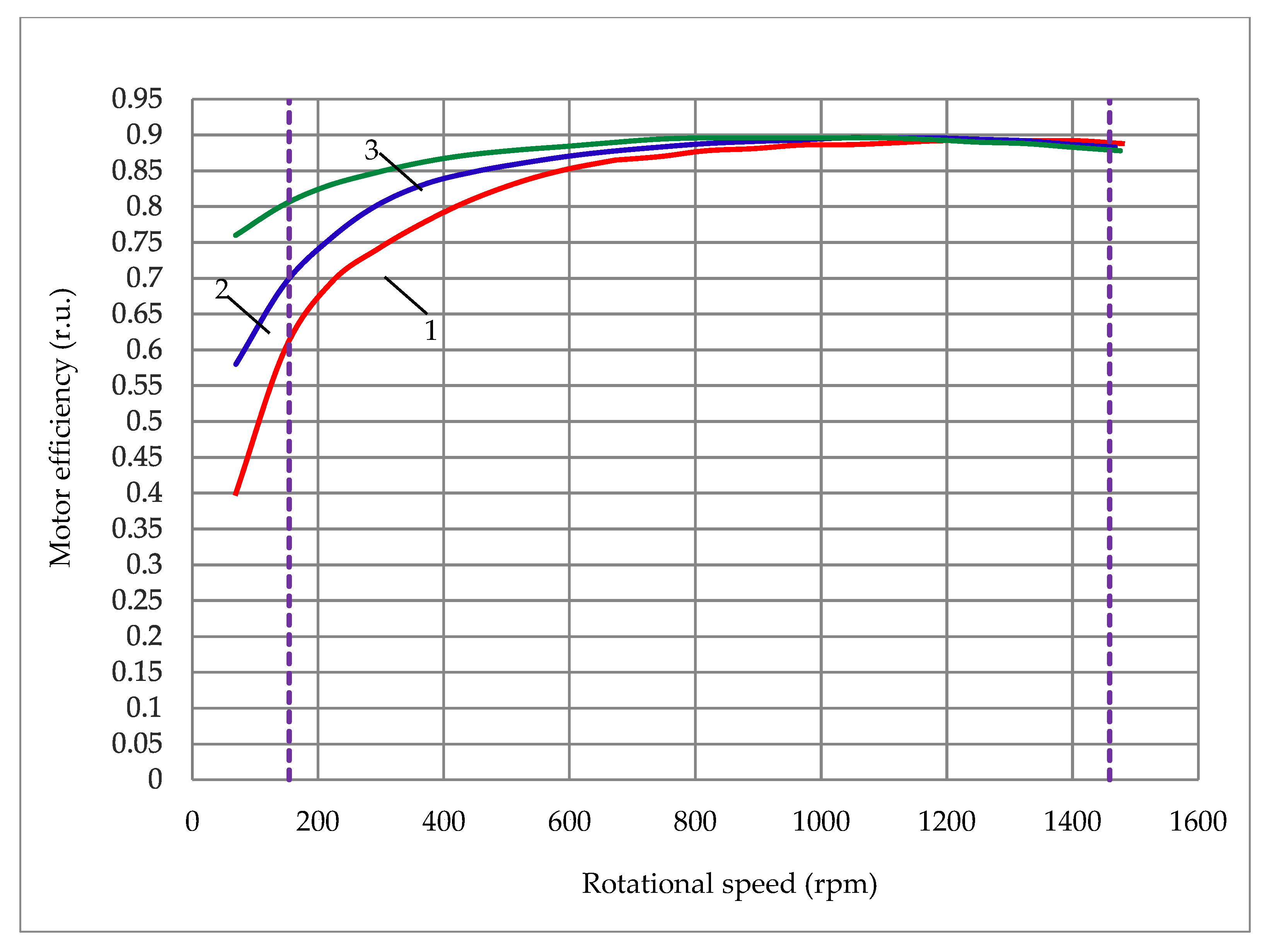
Figure 4 shows the dependence of changes in motor efficiency (serial motor, 1st modification, 2nd modification) in the control range.
The system of constraints on parameters and performance indicators comprises two groups of constraints: functional constraints and design and manufacturing constraints. The latter are established not only in accordance with requirements dictated by the physical properties of the materials used in engines and applicable standards, but also taking into account the technological capabilities of the manufacturing process.

5. Modeling in the MATLAB/Simulink Environment

As a result of modeling in MATLAB/Simulink, energy indicators are determined both at the motor input and at the drive input. These include efficiency coefficients ƞ, phase shift c o s φ , and power χ. Calculations were performed for the values of the fundamental harmonic powers: total S 1 ( k V A ) , active P 1 ( k W ) , and reactive Q 1 ( k V A r ) . Power components were calculated taking into account all harmonics: total S ( V A ) , active P   ( k W ) and reactive D ( V A r ) . The reactive power D has two components. The first is Q 1 , caused by the phase shift in the fundamental harmonic of the current relative to the fundamental harmonic of the voltage. The second component is T, which determines the distortion power. These components are related by the following expression: D 2 = Q 1 2 + T 2 [15,28].
In the MATLAB/Simulink environment, the FCAED model based on a two-stage converter is presented in [15]. A description of the model is also provided there. The parameters of the equivalent circuit for the 4A180S4 series-wound induction motor and the load characteristic of the pump, which are used for modeling the drive in this article, are given below. When modeling a drive with a modified motor, the corresponding parameters of the modified motor’s equivalent circuit are used, whilst the load characteristic of the pump system remains unchanged.
The voltage generated by the frequency converter is supplied to a four-pole induction motor with a squirrel-cage motor with P n = 22   k W ; U n = 380   V ; f n = 50   H z .
The inductance and resistance of the stator are R s = 0.18   O m ; L s = 1.3   m H . The parameters are similar, but the values for the rotor are R r = 0.08   O m ;   L r = 1.78   m H . The mutual inductance is L m = 0.0535   H . The motor operates at a previously defined load characteristic, which is described by the equation:
M ( ω ) = 10.1 + 0.006   ω 2 .
The load characteristic equation is influenced by the magnitude and nature of the load type, which is determined by the application of the specific drive. When calculating the differential equations, a variable step was selected using the ‘discrete (no continuous state)’ method. The calculation step size was set to 2 µs. By varying the output frequency of the converter from 5 to 50 Hz, the rotational speed of the standard motor is regulated from 147.6 rpm to 1464 rpm.
Measurement blocks for instantaneous voltage and current signals obtained from sensors, similar to those described in [29], were used. The calculated power allows us to determine the efficiency, shift, total harmonic distortion, and power coefficients at both the motor input and the drive input. The total harmonic distortion (THD) coefficients can also be found from the results of oscillogram processing:
T H D U = v U v U 1 2 ;
T H D I = v I v I 1 2 .
The power coefficients are determined using harmonic spectra of currents and voltages [28]:
χ = c o s φ 1 + T H D U 2 + T H D I 2 + T H D U 2 · T H D I 2 .
When determining the power factor at the drive input, an infinite power source with undistorted three-phase voltage on a distorting load is assumed, then the power factor of the electric drive is determined by the expression [15,30]:
χ = c o s φ 1 + T H D I 2 .
The DIMASDrive program enables the calculation of equivalent circuit parameters, which in turn serve as input data for simulation in the MATLAB/Simulink environment.
The serial motor and its modification have the following equivalent circuit parameters (Table 5), which are used as initial data for calculations in MATLAB/Simulink.
The results of modeling drives using a standard 4A180S4 motor and its modification in the MATLAB/Simulink environment are presented in Table 6 and Table 7. They show the energy indicators at the input of the drives of the variants under consideration, as well as the efficiency of the frequency converter.
In Table 6 and Table 7, differences are observed in the values of currents, power, and rotational speeds. These energy indicators are practically identical according to the results of modeling drives with a serial motor and its modification.

6. Calculation of the Range Criterion for Drive Costs

Using the optimization criterion—the efficiency of an induction motor—does not provide complete information about the quality of a controlled drive. As mentioned above, quality can be represented by an innovative criterion of the reduced costs of the electric drive, which takes into account not only the cost and energy efficiency of the drive, but also the costs of compensating for reactive power and distortion power, which characterize the electromagnetic and energy compatibility of the drive with the network. At present, the cost component of distortion compensation is not taken into account in the discounted cost criterion; consequently, the quality of the drive, expressed in monetary terms, is assessed incompletely and is therefore underestimated. A method for calculating this component and incorporating it into the discounted cost criterion is proposed.
The required calculations are described in detail in [15]. In the calculations performed, most of the parameters used in the economic model were taken from the design methodology for general-purpose induction motors ( k d = 0.065 —proportion of costs for depreciation, k s = 0.069 —proportion of costs for maintenance during drive operation, k m y = 0.25 —the FCAED’s contribution to peak loads, t g φ 0 = 0.484 , where φ 0 —the phase angle between the FCAED’s current and voltage at which reactive power need not be compensated, a r = 0.04 —a coefficient accounting for losses in distribution networks. The cost of 1 kWh of active energy c a e = 1.5 c.u. and the annual operating time of the drive t E D = 2000   h are assumed. The cost of installing 1 kVAR of reactive power compensation equipment c k 1 = 10   c . u . and the cost of installing 1 kVAR of distortion power compensation equipment c k 2 = 10   c . e . were adopted following an analysis of price lists from electrical engineering companies, in particular, ELHAND, Poland, which manufactures chokes and filters.
In the operating modes under consideration, in the first mode, the drive operates in the control range of 148–1440 rpm, and for this range, the average values of the coefficients and the active power consumed by the FCAED are determined.
In the second mode, the drive operates according to a specified tachogram (3600 s—200 rpm; 3600 s—600 rpm; 3600 s—1400 rpm), and the coefficients and active power consumption are calculated using the corresponding expressions given in [15].
With a payback period of 5 years and an average inflation rate of 4%, the inflation factor will be 1.083. Further calculations used the permissible total harmonic distortion coefficient T H D I D = 20 % . We also assume that the cost of a drive with a 4A180S4 series motor is 6000 c.u. (the cost of a frequency converter is 5000 conventional units and the cost of a 4A180S4 series motor is 1000 c.u.).
It is now common practice to evaluate the performance of controlled asynchronous electric drives using MATLAB Simulink, which makes it possible to compare different drive configurations.
One of the reasons for the overestimated efficiency values of the induction motor calculated in MATLAB/Simulink, compared with the efficiency values obtained using the DIMAS program, is that MATLAB/Simulink does not account for core losses (both main and additional), mechanical losses, and stray losses in the motor. As a result, the mid-range efficiency of the drive with the standard induction motor 4A180S4 increases by a factor of 1.097, while the overall efficiency over the operating range, taking into account the tachogram, increases by a factor of 1.12. A similar increase is observed for the drive with the second modification of the standard motor (the mid-range efficiency increases by a factor of 1.049, and the range efficiency with the tachogram by 1.051). For a correct calculation of the cost criterion, it is proposed to recalculate the drive efficiency using the efficiency of the frequency converter obtained from MATLAB/Simulink simulations and the efficiency of the induction motor obtained from simulations using the DIMASDrive program.
In accordance with the methodology for calculating the range criterion for the given costs:
D C C = C E D + C r p c 1 + C r p c 2 · 1 + ( k d + k s ) + C L ;
as set out in [15], given known values for the drive cost CED and range values (either average-range or range values taking into account the tachogram) for ɳ ,   c o s φ ,   P 1 and χ, the components of the criterion can be calculated: costs associated with reactive power compensation:
C r p c 1 = c k 1 · k m y · P 1 · t g a r c c o s φ t g φ 0 · t E D ;
costs of compensating distortion power:
C r p c 2 = c k 2 · k m y · P 1 · { [ t g ( a r c c o s χ ) ] 2 [ t g ( a r c c o s φ ) ] 2 t g [ a r c c o s 1 1 + T H D I D 2 + T H D U D 2 + T H D I D 2 · T H D U D 2 ] } · t E D ;
and the annual cost of electrical energy losses:
C L = c a e · P 1 · ( 1 + a r n ) · t E D .
It should be noted that, in this case, reactive power compensation need not be taken into account, as t g φ 0 is significantly less than 0.484.
To account for inflation, it is advisable to represent the criterion as two components: initial capital investments:
K = C E D + C r p c 1 + C r p c 2 ;
and annual costs:
Y = ( k d + k s ) ( C E D + C r p c 1 + C r p c 2 ) + C L .
Table 8 shows the results of the calculations.
Similarly, calculations were performed for the FCAED with the second modification of the 4A180S4 series engine (Table 9). The inflation coefficient and the permissible coefficient of non-linear current distortion remained the same. We also assume that the cost of the drive is 6200 conventional units, since the cost of the third modification of the serial engine increased by 200 conventional units.
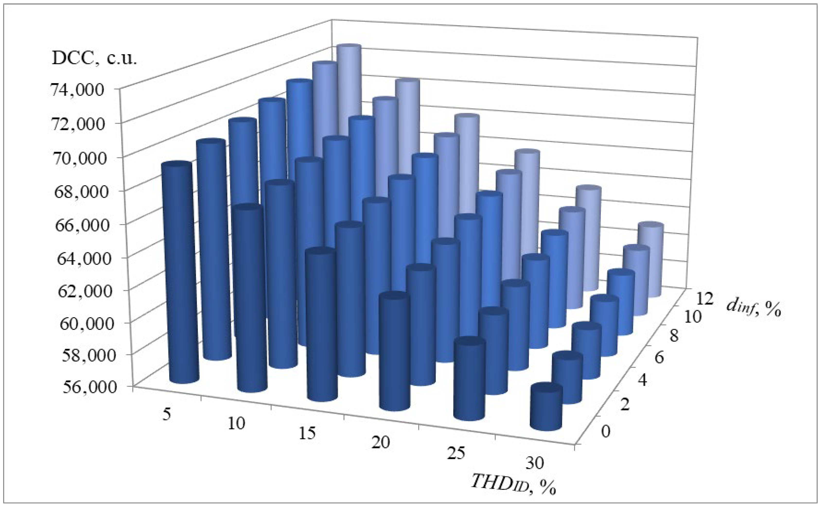
Sensitivity of the DCC criterion to the inflation coefficient and the permissible value of T H D I D can be considered for one of the FCAED variants. Figure 5 shows the values of the mid-range DCC criterion for an electric drive with a motor of the second modific.

7. Conclusions

The design of variable-speed induction motors for the variable-frequency drive of a pump unit is carried out on the basis of the motor and drive control characteristics, which are derived taking into account the nature, magnitude, and control range represented by the load characteristic of the pump unit. The optimization procedure implemented in the DIMASDrive program makes it possible to modify the structure and design parameters of the base standard motor in order to achieve a better value of the design criterion, namely motor efficiency. At the same time, the quality of a given design variant of the variable-speed drive is fully assessed using an innovative range-based reduced-cost criterion. To determine this criterion, the design variants are simulated in the MATLAB/Simulink environment. This criterion takes into account not only the cost and energy efficiency of the drive, but also the costs of compensating reactive power and distortion power, which characterize the drive’s energy and electromagnetic compatibility with the grid. By comparing the reduced costs of several design variants, the preferred option is selected as the one characterized by the minimum reduced cost.
The presented results were obtained entirely through simulations conducted using validated software. Experimental studies of the prototype will provide the final answer regarding the solution.
  • For modeling and subsequent optimization of the FCAED, it is necessary to represent the load mechanism (pump unit) as a function n(M).
  • In the structural and parametric optimization used in these studies, performed using the DIMASDrive program, an increase in the engine’s range efficiency is observed. The average range efficiency of the serial motor is 83.3%, and the average range efficiency of the 2nd modification motor is 88.7%. A similar ratio applies to range efficiency taking into account the tachogram, 79.2% versus 87%.
  • It is proposed to use the motor efficiency values obtained with the DIMASDrive program, since MATLAB/Simulink does not account for core (iron) losses, mechanical losses, and additional losses in the motor, which leads to an overestimation of the motor’s efficiency.
  • It has been confirmed that, within the considered control range, the input phase shift coefficients of the drives are nearly identical and close to unity for the considered cases of frequency—controlled asynchronous electric drives. The power factors and THDi are also virtually identical.
  • The criterion for the costs incurred must take into account the need to compensate not only for reactive power, but also for distortion power. For the first time, it has been proposed that the calculation of the bandwidth criterion should take into account the costs of compensating for the distortion power that determines the drive’s electromagnetic compatibility.
  • The medium-range innovative criterion for the drive’s reduced costs is reduced by 3.6% when an optimized motor (2nd modification) is used instead of a standard motor.
  • With the given values of the cost of installing 1 kVAr distortion power compensation devices (10 c.u. is assumed in the calculations) and the permissible total harmonic distortion factor (20% is assumed in the calculations), a significant portion of the reduced cost criterion is accounted for by the costs of distortion compensation.
  • The values of the reduced cost criterion depend on the operating load mode. In the examples considered, the DCC values differ when the control range is taken into account and when the drive operating tachogram is taken into account.
  • The value of the drive’s DCC criterion is influenced by a number of factors, including the inflation coefficient and the permissible value of T H D I D .
  • The criterion of reduced costs, which allows the quality of various drive options to be fully assessed using a cost indicator, can be used both in research on existing drives and in the optimized design and multi-faceted modeling of controlled asynchronous electric drives.

Author Contributions

Conceptualization, M.Z. and V.P.; Methodology, V.P. and M.Z.; Software, R.Y. and K.G.; Validation, formal analysis, R.Y. and J.P.; Investigation, V.P.; Resources, V.P., N.A. and R.Y.; Writing—original draft, V.P.; Writing—review and editing, R.Y. and J.P.; Supervision, V.P. and M.Z. All authors have read and agreed to the published version of the manuscript.

Funding

This research received no external funding.

Data Availability Statement

Data are contained within the article. The data are presented within the article itself.

Conflicts of Interest

The authors declare no conflicts of interest.

Nomenclature

IMinduction motor
χ power factor
T H D I total harmonic distortion of current
T H D U total harmonic distortion of voltage
T H D I D total harmonic distortion coefficients of currents
ɳ c d mid-range efficiency criterion
χ c d mid-range power factor criterion
c o s φ c d mid-range shift coefficient criterion
ɳ d t range criterion of efficiency taking into account the tachogram
χ d t range criterion of power factor taking into account the tachogram
c o s φ d t range criterion of the phase shift factor taking into account the tachogram
P 1 c d mid-range active power consumption
P 1 d t range active power consumption taking into account the tachogram
D C C c d mid-range discounted costs
D C C d t range discounted costs taking into account the tachogram
C r p c 1 cost of reactive power compensation of the first kind
C r p c 2 cost of reactive power compensation of the second kind
C L cost of active losses
Kcapital expenditures
C E D drive cost
Y i annual operating costs
d I N F annual inflation coefficient
k I N F 1 average inflation coefficient

References

  1. Leznov, B.S. Variable Frequency Electric Drive of Pumping Units; Mashinostroenie: Moscow, Russia, 2013; 176p, Available online: https://www.studmed.ru/leznov-b-s-chastotno-reguliruemyy-elektroprivod-nasosnyh-ustanovok_617cba0cfe0.html (accessed on 12 May 2026).
  2. Elovik, V.L.; Voitov, I.V.; Sedlukho, Y.P. Calculation and Analysis of Operating Modes of Centrifugal Pumps with Variable Frequency Electric Drive; BGTU: Minsk, Belarus, 2022; 110p, Available online: https://www.twirpx.com/file/4489937/ (accessed on 12 May 2026).
  3. Lazarev, G.B. Variable-frequency electric drive of pumping and ventilation units. Silov. Elektron. №3 2007, 41–48. (In Russian). Available online: https://power-e.ru/electrodrives/chastotno-reguliruemyj-elektroprivod-nasosnyh-i-ventilyatornyh-ustanovok/ (accessed on 12 May 2026).
  4. Ionel, M.; Stan, M.-F.; Ivanovici, T.D.; Enescu, D.; Virjghe, E.O.; Ionel, O.-M. Strategies for Increasing energy efficiency in electrical drives. In Advances in Computational Intelligence, Man-Machine Systems and Cybernetics; WSEAS Press: Bucharest, Romania, 2010; Available online: https://www.researchgate.net/publication/228697212_Strategies_for_increasing_energy_efficiency_in_electrical_drives (accessed on 12 May 2026).
  5. Jahmeerbacus, M.I. Flow rate regulation of a variable speed driven pumping system using fuzzy logic. In Proceedings of the International Conference on Electric Power and Energy Conversion Systems (EPECS), Sharjah, United Arab Emirates, 24–26 November 2015. [Google Scholar] [CrossRef] [Scilit]
  6. Bordeasu, D.; Prostean, O.; Filip, I.; Vasar, C. Adaptive control strategy for a pumping system using a variable frequency drive. Machines 2023, 11, 688. [Google Scholar] [CrossRef] [Scilit]
  7. Arun Shankar, V.K.; Umashankar, S.; Paramasivam, S.; Sanjeevikumar, P.; Dileep Sailesh, K.N. Experimental investigation of VFD-fed scalar control of induction motor for pumping application. In Lecture Notes in Electrical Engineering; Springer: Singapore, 2018; Volume 435, pp. 287–295. [Google Scholar] [CrossRef] [Scilit]
  8. Muravleva, O.O.; Vehter, E.V.; Zharikova, T.V. Evaluation of the Influence of Energy Characteristics of an Induction Motor on the Energy Saving of a Pumping Unit. Available online: http://earchive.tpu.ru/handle/11683/575 (accessed on 12 May 2026).
  9. Ahmed, A.A.; Moharam, B.A.; Rashad, E.E. Efficiency improvement of water-pumping systems based on field-oriented speed control of IM drive. In Proceedings of the Nineteenth International Middle East Power Systems Conference (MEPCON), Cairo, Egypt, 19–21 December 2017; pp. 881–887. [Google Scholar] [CrossRef] [Scilit]
  10. Cookson, T.J.; Lang, N.G.; Thornton, E.J. Adjustable speed drives applied to large AC induction motor and pump systems. IEEE Trans. Ind. Appl. 2000, 36, 164–171. [Google Scholar]
  11. Shestakov, I.V.; Safin, N.R. Evaluation of the necessity of induction motor modification and control aspects when operating with frequency converters. Energy Saf. Energy Sav. 2019, 2, 44–48. [Google Scholar] [CrossRef] [Scilit]
  12. Zakharov, A.V. Scientific Foundations of Energy Calculation and Design of AC Electrical Machines for Mechatronic Systems. Ph.D. Thesis, Vladimir State University, Vladimir, Russia, 2017. Available online: https://www.dissercat.com/content/nauchnye-osnovy-energeticheskogo-rascheta-i-proektirovaniya-elektricheskikh-mashin-peremenno?utm_source (accessed on 12 May 2026).
  13. Sarac, V. Design optimization of induction motor for efficiency and reliability improvement. In Lecture Notes in Networks and Systems; Springer: Singapore, 2021; Volume 369, pp. 35–49. [Google Scholar] [CrossRef] [Scilit]
  14. Apaydin, H.; Oyman Serteller, N.F.; Oğuz, Y. Induction motor geometric parameter optimization using a metaheuristic optimization method for high-efficiency motor design. Energies 2025, 18, 733. [Google Scholar] [CrossRef] [Scilit]
  15. Petrushyn, V.; Plotkin, J.; Horoshko, V.; Yenoktaiev, R.; Yakimets, A. Comparison of the discounted costs of controlled asynchronous electric drives with matrix and with DC-link frequency converters. Int. J. Power Electron. Drive Syst. 2025, 16, 2307–2320. [Google Scholar] [CrossRef] [Scilit]
  16. Gupta, A.; Machavaram, R.; Kshatriya, T.; Ranjan, S. Multi-objective design optimization of a three phase squirrel cade induction motor for electric propulsion system using genetic algorithm. In Proceedings of the 2020 IEEE First International Conference on Smart Technologies for Power, Energy and Control (STPEC), Nagpur, India, 25–26 September 2020. [Google Scholar] [CrossRef] [Scilit]
  17. Antonelli, S.L.; Donolo, P.D.; Pezzani, C.M.; Quispe, E.C.; De Angelo, C.H. Identification of Induction motor parameters using genetic algorithms. In Proceedings of the 2023 IEEE Workshop on Power Electronics and Power Quality Applications (PEPQA), Cali, Colombia, 5–6 October 2023; pp. 1–7. [Google Scholar] [CrossRef] [Scilit]
  18. de Almeida, A.T.; Ferreira, F.J.T.E.; Both, D. Technical and economical considerations in the application of variable-speed drives with electric motor systems. IEEE Trans. Ind. Appl. 2005, 41, 188–199. [Google Scholar] [CrossRef]
  19. Bordeasu, D.; Dragan, F.; Filip, I.; Szeidert, I.; Tirian, G.O. Estimation of centrifugal pump efficiency at variable Frequency for Irrigation Systems. Sustainability 2024, 16, 4134. [Google Scholar] [CrossRef] [Scilit]
  20. Petrushin, V.; Vodichev, V.; Yenoktaiev, R.; Plotkin, J. Design criteria and range limits in the development of controlled induction motors. Int. J. Electr. Eng. Inform. 2019, 11, 451–462. [Google Scholar] [CrossRef] [Scilit]
  21. German-Galkin, V.; Sakharov, V.; Tarnapowicz, D. Energy characteristics of asynchronous electric drive DC-link frequency converters. Manag. Syst. Prod. Eng. 2019, 27, 51–54. [Google Scholar] [CrossRef] [Scilit]
  22. Saghafinia, A.; Ping, H.W.; Uddin, M.N.; Amindoust, A. Teaching of simulation an adjustable speed drive of induction motor using MATLAB in advanced electrical machine laboratory. Procedia Soc. Behav. Sci. 2013, 102, 96–104. [Google Scholar] [CrossRef] [Scilit]
  23. Oladipo, F.; Temitayo, O.; Eziafa, O. Analysis of the effect of electric and magnetic loadings on the design parameters of an induction motor and Its Performance using MATLAB/Simulink. Int. J. Eng. Res. Appl. 2015, 5, 38–43. [Google Scholar]
  24. Le Roux, P.F.; Ngwenyama, M.K. Static and dynamic simulation of an induction motor using MATLAB/Simulink. Energies 2022, 15, 3564. [Google Scholar] [CrossRef] [Scilit]
  25. Salih, H.R.; Abdulrazzaq, A.A.; Guzun, A.A. Dynamic Modeling of Pump Drive System Utilizing Simulink/MATLAB Program. Int. Res. J. Eng. Technol. 2016, 3, 21–24. [Google Scholar]
  26. Mencou, S.; Yakhlef, M.B.; Tazi, E.B. Advanced Control of Induction Motors (2019–2025): A Comprehensive review of strategies, algorithms and sensorless techniques. Adv. Electr. Eng. Electron. Energy 2025, 14, 101098. [Google Scholar] [CrossRef] [Scilit]
  27. Gevorkov, L.; Domínguez-García, J.L.; Rassõlkin, A.; Vaimann, T. Comparative Simulation Study of Pump System Efficiency Driven by Induction and Synchronous Reluctance Motors. Energies 2022, 15, 4068. [Google Scholar] [CrossRef] [Scilit]
  28. Petrushyn, V.; Horoshko, V.; Plotkin, J.; Almuratova, N.; Toigozhinova, Z. Power balance and power factors of distorted electrical systems and variable speed asynchronous electric drives. Electronics 2021, 10, 1676. [Google Scholar] [CrossRef] [Scilit]
  29. Klimash, S.; Klimash, V.; Vlasayevsky, S. Specialized modules for calculation of energy coefficients of electrical engineering devices in Matlab. Electrotech. Syst. Complexes 2017, 3, 11–16. [Google Scholar] [CrossRef] [Scilit]
  30. Firago, B.I.; Palyavchik, L.B. The theory of electric drive. In Techno Perspective; Vysheysha Shkola: Minsk, Belarus, 2007; Available online: https://obuchalka.org/20241006165725/teoriya-elektroprivoda-firago-b-i-pavlyachik-l-b-2007.html (accessed on 12 May 2026).
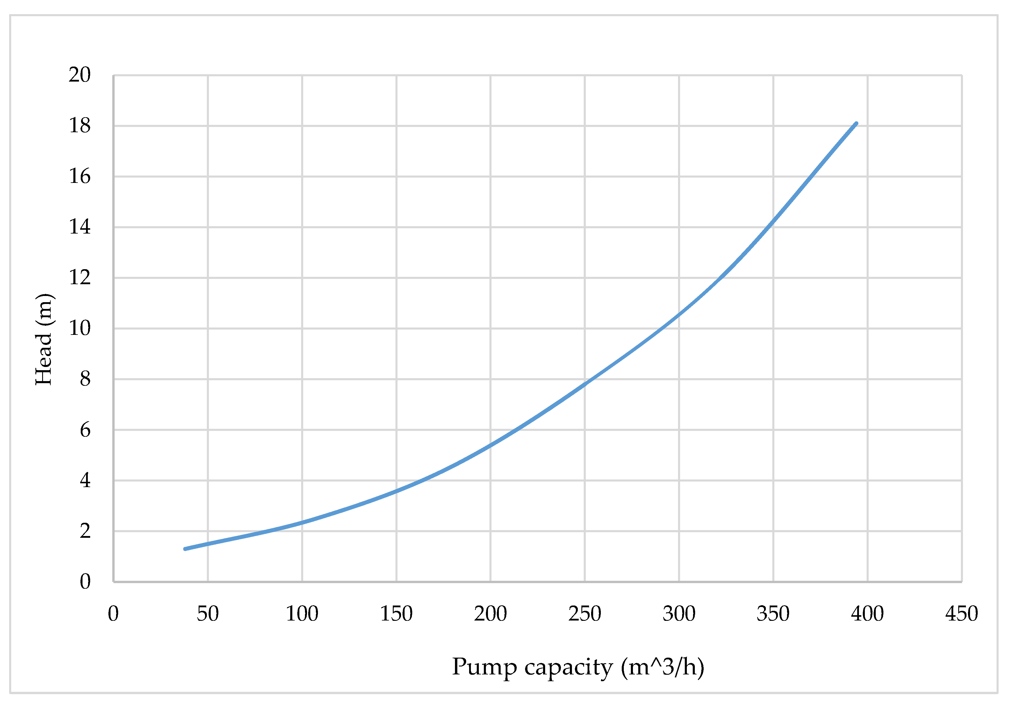
Figure 1. Characteristics of the change in the parameters of the H and Q axial pump.
Designs 10 00056 g001
Figure 2. Family of mechanical characteristics of the 4A180S4 series motor and load characteristic of the pump.
Designs 10 00056 g002
Figure 3. Thermal characteristics of the proposed motors. Dashed lines denote the adjustment range.
Designs 10 00056 g003
Figure 4. Dependences of the change in the efficiency of the motors in the control range 1—serial motor; 2—modification one; 3—modification two. Dashed lines denote the adjustment range.
Designs 10 00056 g004
Figure 5. Dependence of the DCC criterion on the inflation coefficient and the permissible value of T H D I D .
Designs 10 00056 g005
Table 1. Transition from dependence H = f(Q) to dependence n = f(M).
n, rpmQ, m3/sQ, m3/hH, m ɳ p u m p P , kWM, N·m
1480.01139.431.350.8030.17511.5
3970.0299107.642.540.8110.91422
6620.0499179.644.650.8242.77240
9270.069250.008.00.8336.52467
11920.0898323.2811.90.84612.476100
14400.11393.0018.10.85222.922150
Table 2. Values of variable variables.
Variable
Parameters
w1qeff, mm2 d i n s , mm L, mmH1,
mm
GP,
mm
ZR
-
A2,
mm
D1,
mm
D2,
mm
Serial IM923.681.3314525113833.758.93.2
2nd modification905.071.535203.728.3123826.38.93.8
Table 3. Values of mid-range efficiencies.
Serial motor 4A180S4 ɳ I M m . r . = 0.833
1st modification ɳ I M m . r . = 0.865
2nd modification ɳ I M m . r . = 0.887
Table 4. Range efficiency values taking into account the tachogram.
Serial motor 4A180S4 ɳ I M t a c h . = 0.792
1st modification ɳ I M t a c h . = 0.835
2nd modification ɳ I M t a c h . = 0.87
Table 5. Parameters of the equivalent circuit of the serial motor and its second modification.
Parameters Motor r 1 , Om r 2 , Om x 1 , Om x 2 , Om x m , Om
Serial 4A180S40.180.080.420.5616.8
2nd modification0.1560.1170.670.11733.3
Table 6. At the drive input when using a serial motor.
f, HzU, VI, AP, kWn, rpmcosφTHDIχ ɳ F C
5218.30.840.281480.9981.670.5130.858
10218.31.760.602960.9991.620.5230.950
15218.33.491.224450.9961.570.5350.963
20218.36.182.245930.9971.490.5540.985
25218.310.23.837400.9951.410.5740.994
30218.315.856.188860.9921.330.5950.992
35218.322.919.2710320.9891.250.6180.998
40218.330.1912.6111510.9861.180.6379.928
45218.342.8718.7913220.9821.080.6680.992
50218.355.6125.2114640.9791.000.6920.986
Table 7. At the input of the drive when using the motor of the 2nd modification.
f, HzU, VI, AP, kWn, rpmcosφTHDIχ ɳ F C
5218.30.660.221450.9991.670.5120.932
10218.31.590.542950.9991.630.5210.959
15218.33.281.154440.9971.570.5340.974
20218.36.082.055910.9971.490.5540.972
25218.39.993.757370.9951.420.5730.99
30218.315.546.058820.9931.330.5940.995
35218.322.479.0710240.9891.250.6160.996
40218.329.5812.3211410.9871.180.6360.992
45218.341.9918.2913080.9831.080.6650.991
50218.354.2124.4614440.9791.010.6890.988
Table 8. Drive indicators with a 4A180S4 series motor.
OptionsMid-RangeFor the
Tachogram
Mid-Range
Adjusted for
Inflation
For the Tachogram Adjusted for Inflation
Indicators
η0.8090.7560.8090.756
CED, c.u.6000600060006000
cosφ0.9920.9920.9920.992
P1, kW8.028.288.028.28
χ0.5910.5820.5910.582
Crpc2, c.u.46,47549,32546,47549,325
CL, c.u.5558705455587054
K, c.u.52,47555,32552,47555,325
Y, c.u.12,58914,46813,63415,668
DCC, c.u.65,06469,79366,10970,993
Table 9. Drive indicators using the second modification of the 4A180S4 serial motor.
OptionsMid-RangeFor the
Tachogram
Mid-Range
Adjusted for
Inflation
For the Tachogram
Adjusted for Inflation
Indicators
η0.8680.8420.8680.842
CED, c.u.6200620062006200
cosφ0.9920.9920.9920.992
P1, kW7.818.267.818.26
χ0.5890.5790.5890.579
Crpc2, c.u.45,53749,65945,53749,659
CL, c.u.4029490640294906
K, c.u.51,73755,85951,73755,859
Y, c.u.10,96212,39111,87113,419
DCC, c.u.62,70068,25063,60969,279
Disclaimer/Publisher’s Note: The statements, opinions and data contained in all publications are solely those of the individual author(s) and contributor(s) and not of MDPI and/or the editor(s). MDPI and/or the editor(s) disclaim responsibility for any injury to people or property resulting from any ideas, methods, instructions or products referred to in the content.