1. Introduction
The growing emphasis on environmental sustainability and energy efficiency has significantly accelerated the electrification transition in the aviation industry. Accordingly, both industrial and academic interest in this area has increased substantially. Moreover, numerous organizations have established goals to support the development of aircraft that align with these principles. In 2021, under the Net Zero 2050 program introduced by the International Air Transport Association (IATA), airlines representing more than 120 countries pledged to reach net-zero carbon emissions by 2050 [
1]. Similarly, the European Union has conducted the Fit for 55, which aims to reduce carbon emissions by at least 55% by the year 2030 [
2].
While the ultimate objective remains the achievement of zero-emission aviation, current research and development efforts have predominantly focused on the More Electric Aircraft (MEA) concept, which aligns more realistically with existing technological capabilities. The main objective of the MEA is to increase the integration of electrical power by replacing conventional systems—such as hydraulic, mechanical, and pneumatic—with electrically powered alternatives.
The initial milestone toward the transition of the MEA concept was noticeable by the replacement of conventional hydraulic actuators with electromechanical actuators [
3]. The MEA has led to a reduction in overall weight and improvements in efficiency, which in turn have contributed to decreased fuel consumption, enhanced maintainability, and increased operational reliability [
4]. In civil aviation, Boeing’s B787 Dreamliner and Airbus’s A350 XWB, and in military aviation, Lockheed Martin’s F-35 Lightning II, represent prominent examples of the MEA application [
5,
6,
7,
8,
9].
As electrical power reaches an increasingly central role in modern aircraft systems, efforts to maximize system efficiency and conduct advanced optimization studies have become crucial. Accordingly, the literature includes a number of studies specifically focused on electric power architectures. In one study, four different high-voltage DC architectures were comparatively evaluated in terms of performance and reliability, which led to the identification of an optimal configuration [
10]. Another research employed the Adaptive Tabu Search algorithm to address the design and optimization of electrical systems within the MEA framework [
11]. In a separate study—focused on hybrid emergency power systems for an MEA platform—a machine-learning-based energy management strategy was developed, and its impact on system performance was analyzed through comparative assessments [
12]. In another study, phase balancing and feeder balancing were evaluated as weight-saving factors, and the backgrounds of these solutions were provided [
13]. Energy management and optimization have become key considerations across other aerospace applications, also beyond aircraft [
14,
15,
16,
17,
18,
19,
20,
21].
Weight remains one of the most critical and constraining parameters in aerospace system design and continues to be a primary focus of engineering research and optimization efforts. Achieving weight reduction both at the equipment level and within overall electrical power system architecture has become a fundamental design objective. In the context of MEA, where electrical systems represent a relatively larger share of total weight, optimization-driven enhancements deliver correspondingly significant benefits.
One of the noteworthy contributors to the overall weight of aircraft electrical power systems is the wiring infrastructure that provides electrical transmission between components. Although cables primarily serve as electrical interfaces, they both influence and are influenced by a wide range of other design parameters. Therefore, their integration into aircraft systems requires a multidisciplinary design approach, where various constraints and performance objectives must be simultaneously addressed [
22].
Main power cables represent one of the most critical design parameters in terms of weight factor for electric aircraft. In this context, a study carried out in 2023 investigated cable optimization for a wide-body aircraft, focusing on weight and reliability considerations [
23]. In 2025, another study proposed new electrical system architectures for a 90-seat electric aircraft concept, with the primary goal of reducing cable weight [
24]. Comparative results were obtained through the assessment of various architectures and cable types. In [
25], optimization of the aircraft electrical power system was further examined in a multi-objective framework, addressing weight, efficiency, and reliability criteria, while employing network graph representation as the method. Although the simplest approach to reducing wiring weight is increasing system voltage—allowing the use of smaller size cables—challenges such as partial discharge present significant limitations. Increasing voltage levels carry a risk of partial discharge, particularly under high-altitude conditions, because of the low pressure. It can lead to the degradation of cable insulation over time. Accordingly, a methodology was introduced in [
26] to determine the optimum system voltage for MEA with the objective of minimizing cable weight. In 2024, a case study of an electric aircraft demonstrated that the proposed model enabled 3.1% reduction in cable weight without reducing the reliability factor [
27]. A study on the LAP in aircraft electrical systems provided an overview of the topic, analyzing four different optimization methods and highlighting comparisons between them [
28]. Results show that the genetic algorithm using the clearing procedure is the best method for load allocation compared with other solutions in terms of efficiency and variety.
One of the key optimization challenges in aircraft wiring systems is the Load Allocation Problem (LAP), which is defined as the determination of the best distribution unit for the electrical power supply of each load. This decision is critical, as the selection of power supply interfaces has a direct impact on the overall system weight. While most studies on aircraft electrical power system weight optimization focus on primary distribution architecture and equipment, secondary distribution wiring has received limited attention. However, secondary distribution wiring accounts for 0.5–1.5% of the total aircraft weight, representing significant optimization potential. Moreover, it is evaluated that the wiring system has the biggest impact on system weight for future MEA concepts [
29]. This study aims to highlight this gap by proposing a strategy to reduce secondary distribution wiring weight, thereby contributing to more efficient and lightweight electrical power system designs. In the scope of this study, an optimization algorithm for aircraft secondary distribution wiring systems has been developed, and its impact on the overall system has been evaluated through a comparative analysis. The objective of the optimization effort is to minimize the cable weight between power distribution units and electrical loads. The algorithm, named Electrical Power System Planning Strategy (E2P2S), was implemented using CPLEX to solve the LAP.
Section 2 presents an overview of aircraft electrical power systems and assesses the current and state-of-the-art trends.
Section 3 examines the conceptual background and formulation of the LAP. Detailed descriptions of the E2P2S algorithm and the associated optimization problem are provided in
Section 4.
Section 5 evaluates the performance of the proposed algorithm through a case study based on the F-16 Block 50 aircraft. The conclusion and recommendations are discussed in
Section 6.
2. Aircraft Electrical Systems
The ongoing revolution in aircraft technology has introduced a range of impacts on conventional electrical power systems. These include modifications in system architecture, changes in voltage levels, and equipment-level enhancements. This section provides a general overview of developments, with particular focus on aspects that have a significant influence on overall system design.
2.1. New Generation Aircraft Concepts
The conventional voltage levels in aviation—28 VDC and 115 VAC—have become increasingly inadequate for next-generation aircraft due to rising electrical power demands. These voltage levels impose significant limitations on the scope of higher-power aircraft design. The growing demand for electrical power requires a substantial increase in the size of cables used for energy transmission at the same voltage level. This leads to a noteworthy rise in both weight and installation difficulty, which are considered highly unfavorable factors in aircraft design.
To accommodate thinner cables for the same power, an increase in system voltage has become unavoidable. Thus, 270 VDC has gained popularity and is being adopted in next-generation aircraft. The use of high voltage is expected to further escalate in the coming years, potentially reaching levels such as 540 VDC [
30,
31]. These transitions in voltage levels have also driven the widespread adoption of innovative aircraft concepts, such as More Electric Aircraft (MEA), Hybrid Electric Aircraft (HEA), and All Electric Aircraft (AEA).
The MEA concept stands out as the most suitable solution within current technological capabilities. MEA is primarily constructed by replacing traditional hydraulic, mechanical, and pneumatic systems with electrically powered ones. This shift enables the development of aircraft that utilize electrical energy more intensely, offering significant advantages in efficiency, reliability, and maintainability.
Improvements in energy storage devices and the advancement of higher power density electrical equipment are expected to enable widespread usage of electrical energy in propulsion systems. In fact, AEA have become the primary focus for achieving the ultimate goal of zero emissions [
32,
33]. However, this transition is estimated to occur in phases, with HEA, already seen in various projects today, leading the way. This concept, which combines electrical energy with traditional propulsion systems, is planned to evolve into AEA where the propulsion system is entirely powered by electrical energy.
2.2. Recent Developments
The electrification of aviation is directly associated with advancements in electrical system equipment. An important factor for concepts integrating electrical energy into propulsion systems is energy storage, making this a highly popular area of research. The major barrier for batteries is their energy density. It is directly connected to the range of aircraft, remains insufficient with current technology, imposing the use of heavy and large batteries [
34]. Research on alternative energy storage devices continues, and significant developments are expected in this area. Hydrogen has emerged as a promising alternative, with growing research and industrial efforts [
35].
The increasing usage of electrical energy and the transition toward HVDC systems have significantly increased the demand for converters. As system voltage levels vary, it has become crucial to improve power electronics-based equipment like Transformer Rectifier Units (TRUs) and inverters. The development of these components is challenged by the need to handle various voltage levels and higher power ratings while reducing their size, making power density a critically important factor.
The traditional approach of centralized power distribution in aircraft is being phased out in favor of distributed architectures and solid-state power controllers (SSPCs) [
36]. This shift is driven by the need for weight reduction, increased flexibility, and easier maintenance. These solutions are crucial as they aim to minimize the length of power cables by decreasing the distances between equipment and power distribution units.
3. Optimization of Load Allocation Problem
Optimal planning and the development of corresponding strategies in electrical power systems emerge as highly significant concerns [
37]. In this context, optimization studies are conducted to achieve improvements in various areas such as minimizing energy losses, enhancing voltage profiles, and meeting financial objectives. The methodologies employed in these studies predominantly involve traditional, heuristic, metaheuristic, and hybrid algorithms [
38,
39]. The growing complexity of electrical power systems emphasizes the importance of utilizing advanced computational methods to maintain reliable and efficient functionality.
Aircraft electrical power systems share considerable similarities with other electrical power systems, emphasizing the necessity of adopting related strategic methodologies. Nevertheless, in aviation, the objectives can differ from those of other systems. Among the design parameters for aircraft, weight has a decisive role and must be carefully addressed in the design and planning of electrical power systems. Improvements in weight optimization can be aimed at different aspects, while the LAP represents a keystone of these efforts. LAP refers to the optimal allocation of loads among distribution units and busbars within the aircraft’s electrical power system.
The LAP aims to construct the best configuration by considering predefined objectives and system constraints. This problem is formulated as a precise ordering of the system inputs within a finite solution space. Problems of this nature, characterized by a discrete and finite set of possible solutions, are broadly categorized under the domain of combinatorial optimization (CO) [
40]. Although the most optimized result can theoretically be achieved by testing all possibilities, the growth of solution spaces due to the increasing number of inputs and constraints complicates the implementation of simple enumeration [
41]. Accordingly, alternative methodologies are required, prompting the development of advanced algorithms adapted to these complexities. Furthermore, technological advancements in both software and hardware enable the problems to be solved more efficiently and rapidly.
CO is explored in a wide range of literature thanks to its various applications across several fields. However, the solution methodologies in these studies often share similarities. The most prominent methods in this area are genetic algorithms, simulated annealing, integer programming, and tabu search. Over time, the popularity of methods has varied. For instance, the average publication year for studies utilizing simulated annealing is 2.5 years earlier than studies using genetic algorithms [
40].
The LAP in aircraft electrical power systems can be likened to various CO examples. For instance, the Set Cover problem focuses on selecting the lowest number of subsets required to cover all the elements of a given set [
42]. The Knapsack problem, where items with different values and weights must be packed into a fixed capacity bag, serves as another example [
43]. Additionally, the Bin Packing problem, which involves placing a fixed number of items into bins with limited capacity, shares similarities with the LAP [
44]. In this analogy, the bags or bins represent the limited sources in the LAP, while the items to be placed in them represent the loads, characterized by their power requirements and importance.
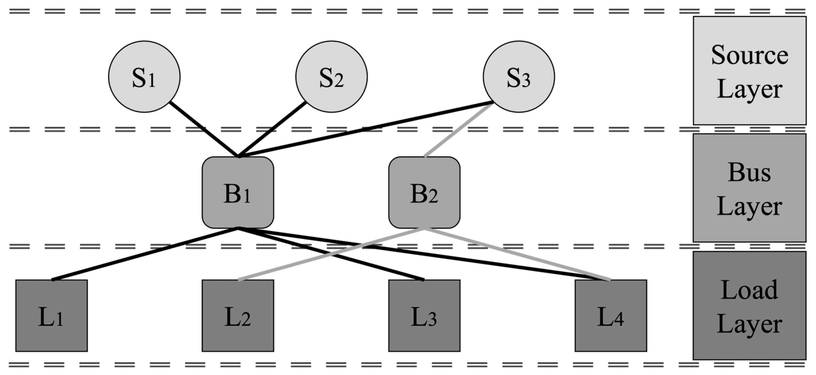
Aircraft electrical power systems are fundamentally composed of layers consisting of sources, buses, and loads. In the example system presented in
Figure 1, the connections between the sources and buses, as well as the buses that supply power to the loads, can be configured using various options.
The system variables can be expressed as follows: S = 3 indicates the number of sources, while B = 2 represents the number of buses. There are 4 loads, which are shown as L = 4. All possible configurations for this system can be calculated in the following manner:
Considering that even in a representative small system, the size of the possible solution space reaches 3969, the evaluation of all possibilities becomes fairly challenging. Moreover, the integration of any constraints further complicates the construction of the solution set, thereby delivering system optimization significantly more intricate.
Although the LAP can be associated with other CO examples, it constitutes a distinct field of study due to the numerous differences. Furthermore, unlike other electric power systems, the objectives and constraints defined from an aviation perspective vary significantly. As a result, the LAP must be examined as a highly specialized domain within aircraft electric power systems. This approach ensures the planning and development of an optimized system design aligned with the objectives of the electric power system.
4. E2P2S: A New Planning Strategy
The previous sections emphasized the advancements in aircraft electrical power systems and their increasingly widespread integration into new generation More Electric Aircraft. Furthermore, developments in electrical power systems have necessitated various optimization studies to understand the growing complexity of such systems. Within this scope, a wide range of studies has been conducted to achieve improvements in both the electrical power system and the overall aircraft. Such studies may be performed across various levels of the system. In this context, optimizing the allocation of aircraft loads to distribution units and the connections between power sources and distribution units to achieve the best possible weight outcome emerges as a significant issue.
A planning strategy is developed for the aircraft electrical power system with a focus on the LAP solution within the context of weight optimization. The primary objective of the Electrical Power System Planning Strategy (E2P2S) is to obtain the most effective distribution of aircraft loads in terms of weight. Additionally, the strategy also incorporates constraints related to system safety, redundancy, and other reasons. In this way, this study aims to overcome a highly complex problem.
4.1. Problem Formulation
4.1.1. Design Variable
The system being optimized identifies the allocation of aircraft load to the distribution units as the variable. Because the distances between the loads and the distribution units vary for each configuration, the mass factor is brought to the forefront. The representation of the system variable x
lb, defined based on load l and distribution unit b, is as follows:
This variable is used in the calculations for the design objective, and its value varies based on the constraints, as defined in the following sections.
4.1.2. Design Objective
In this study, the objective of the LAP solution is to minimize the total mass of the power wires, M
PW, supplying the aircraft loads. This calculation is performed by summing the mass of all the power wires for each load M
L.
The mass of the power wire associated with each load is calculated by multiplying the distance between the load according to its corresponding distribution unit(s) and the unit weight of the wire.
Some aircraft loads are designed to be redundantly powered as a system requirement. Therefore, it must be considered during the calculation of power cable lengths for each load. Hence, the total cable length is obtained by summing the distances computed by the distance function. This function is represented as an L × B matrix, where the rows denote the loads, the columns indicate the distribution units, and the values show the distance between L and B. As a critical input to the algorithm, this function ensures that distances have a direct impact on the results. Constructed from the measured lengths between all loads and distribution units, the distance function can rely on estimated or approximate values during preliminary analyses or precise lengths in a mature design.
The unit weight of the cable is associated with its current rating and presents a parallel relationship with the power rating. Accordingly, the unit weight of a cable is determined based on the power rating by using the weight function. Another essential input of the algorithm is the weight function, which operates as a matrix expressing the unit weights of cables based on the sizes, which is calculated according to the power demands of the loads. In other words, once the appropriate cable size for each load is determined, the corresponding unit weight is used to construct this matrix.
4.1.3. Design Constraints
In unconstrained applications, achieving the objective function is relatively straightforward. For instance, in this particular problem, a solution is generated by assigning all loads to the nearest distribution units. However, real-world scenarios are characterized by numerous limiting factors, necessitating the adaptation of problem-solving approaches to specific conditions. In the planning phase of LAP applications in aviation, many constraints must be considered. This section presents the issues to be addressed within the scope of E2P2S.
Certain aircraft loads are required to be supplied redundantly. That means, in case of a loss of one source or failure, related equipment can be supplied from a different source without any interruption. It is prevented from losing critical loads with one failure condition. Thus, it results that each load must be supplied by two separate distribution units if redundancy is required. Otherwise, the loads must be allocated to only one distribution unit.
Supplying redundant loads from the same bus is not considered appropriate from a system design perspective. The fundamental principle is that, in the case of a power source failure, the load connected to the non-essential bus must continue to be supplied from the battery bus. The main goal of this requirement is to provide a power supply from separate power sources. In this study, the channels connected to the non-essential bus are represented by odd numbers, while the channels connected to the battery bus are denoted by even numbers. Consequently, the sum of the channel numbers supplying a redundantly powered load must be an odd number to ensure proper redundancy.
The electrical loads of the aircraft operate at different voltage levels. For example, if it is considered a system with 115 VAC and 28 VDC, some of the buses are used to supply 115 VAC loads, while some of them are chosen as 28 VDC. Accordingly, each load must be supplied from a distribution unit appropriate to its specific voltage. The δ(l) function is defined to provide the set of distribution units compatible with the operating voltage of load l. This function provides appropriate matching of loads and buses with each other. All loads are connected to proper distribution units with the given constraint by using δ(l):
For specified aircraft functions, multiple identical pieces of equipment or different equipment serving similar purposes are utilized to provide redundancy. For instance, numerous aircraft are equipped with two Mission Computers (MC). The primary objective is to ensure that one MC can take over the functions of the other in case of a failure. Actually, it provides an equipment-level redundancy to the system. As defined in the redundancy constraint, a similar approach is also considered for this requirement. Therefore, related equipment must be powered by separate distribution units to meet operational requirements. Within the scope of LAP, this constraint is expressed as follows:
Developments in the aircraft industry are largely driven by economy-friendly design solutions, which are also expected to play a significant role in the future. The development of aerospace products is highly costly due to the safety and reliability requirements, as well as the extensive testing and certification processes. As a result, equipment performing similar functions is generally developed in a standard configuration instead of multiple alternatives. Accordingly, in the scope of this algorithm, the distribution units are considered to be used as Commercial Off-The-Shelf (COTS) components, and all units are of the same part number. Therefore, the total power demand of each distribution unit must be closely aligned with the others. Otherwise, it can be seen that some of the distribution units could exceed their capacity, resulting in an overload risk. ±25% limit is set for the power demand difference among all distribution units to ensure the selection of the same product.
4.2. Algorithm
Although the design variable, objective function, and constraints of the E2P2S algorithm are defined in the previous section, it is required to express them in algorithmic form beyond mathematical representations. It provides the developed algorithm to be transformed into a functional tool through the use of various software platforms. Depending on the specific characteristics of the application, different software environments may be preferred for implementation. The key point is the adaptation of the algorithm to the structure of the chosen software. In this study, the algorithm is implemented by using CPLEX, a software developed by IBM. CPLEX is widely used in several fields to solve various optimization problems and serves multiple sectors, including logistics, production planning, and financial modeling [
45]. One of the primary objectives of the strategy is to achieve results with minimum computational time. Since the LAP is formulated as a Mixed-Integer Programming problem, the CPLEX solver has been selected instead of other methods due to its efficiency in solution time and the structure of the problem.
The output of the algorithm is the sum of the cable weights corresponding to the connections between the distribution units and all loads. To achieve this, the system must be provided with essential input parameters such as loads and distribution units, distances between loads and distribution units, unit cable weight for each load, redundancy requirements, operation voltage for each load, and power consumption for each load. Additionally, it is required to define a set of variables that are shaped by inputs and directly affect the outcome. The use of certain functions—some of which may be obtained through alternative methods—is also necessary within the process. The pseudocode representation of the E2P2S algorithm is presented in
Appendix A.
4.3. Example
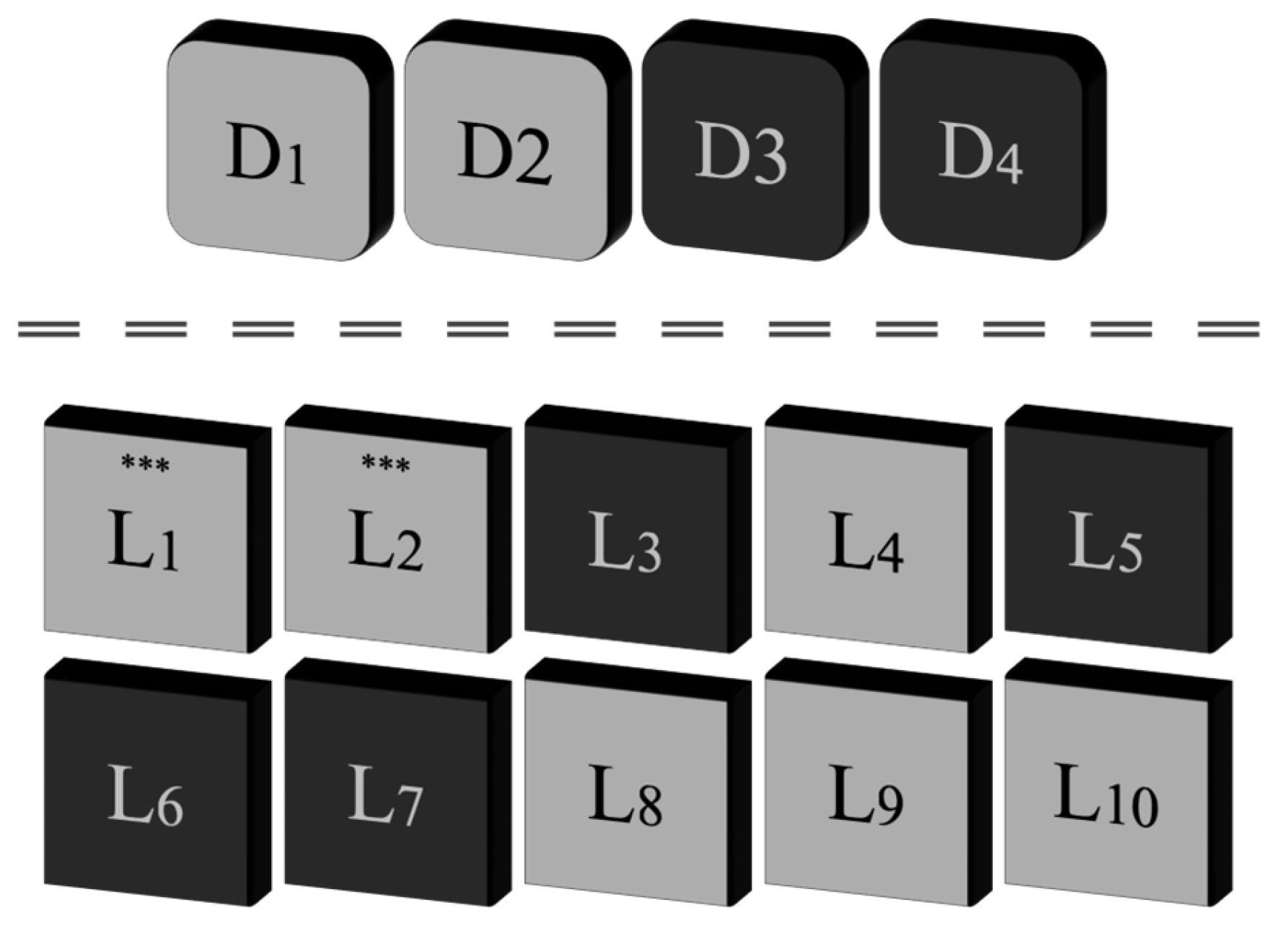
The E2P2S algorithm is evaluated through testing on a representative system, with the findings analyzed in detail. As illustrated in
Figure 2, this system comprises 4 distribution units and 10 loads. It is assumed that units D1 and D2 provide 28 VDC outputs, while D3 and D4 provide 270 VDC outputs. Regarding the loads, L1, L2, L4, L8, L9, and L10 operate at 28 VDC, where L1 and L2 serve as redundant equipment for the same function, and must be supplied from separate distribution units. Meanwhile, L3, L5, L6, and L7 are loads that require a 270 VDC input, with the constraint defined as redundancy of load L6.
As elaborated in the previous sections, the distance function is utilized to compute cable lengths, which is one of the parameters used to calculate cable mass. The representation of the matrix associated with this function is provided in
Table 1. All lengths are indicated as millimeters, which makes calculations easier.
The power rating of the loads is set 10 times higher than their respective ID. For instance, P1 equals 10 W, and P8 equals 80 W. Unit cable weight, which is shown as g/mm unit, is defined for each load as given in
Table 2.
Based on the information provided above, the E2P2S optimization algorithm conducted using CPLEX resulted in a system architecture with a total cable weight of 3120 g. In contrast, it is also found that under the same set of constraints, a randomly assigned configuration could lead to a total cable weight of up to 3680 g. The allocation matrix between distribution units and loads in the optimized system architecture is presented in
Table 3. Each element of the matrix denotes the connectivity status between a given distribution unit and a load. A value of 1 indicates the existence of a cable, whereas a value of 0 signifies no connection between the corresponding pair. Consequently, without applying the E2P2S algorithm, the system could have been subjected to a cable weight increase of approximately 17%.
It is also seen that the system is constructed properly according to the constraint requiring the power difference between distribution units to remain below 25%. In the 28 VDC network, D1 and D2 supply 180 W and 160 W, respectively, while in the 270 VDC network, D3 and D4 supply 130 W and 140 W.
5. Case Study for F-16 Block 50 Aircraft
In this section of the study, the performance of the developed E2P2S algorithm is evaluated through a case study on a representative system. For this purpose, the Block 50 series of F-16 aircraft, produced by Lockheed Martin, is selected as the reference platform. The F-16 is a single-engine multi-role fighter aircraft that is among the most widely produced combat aircraft in history. Since its first flight in 1974, it has been developed through numerous variants and remains actively operational. Detailed specifications of the aircraft are presented in
Table 4.
5.1. EPS Architecture
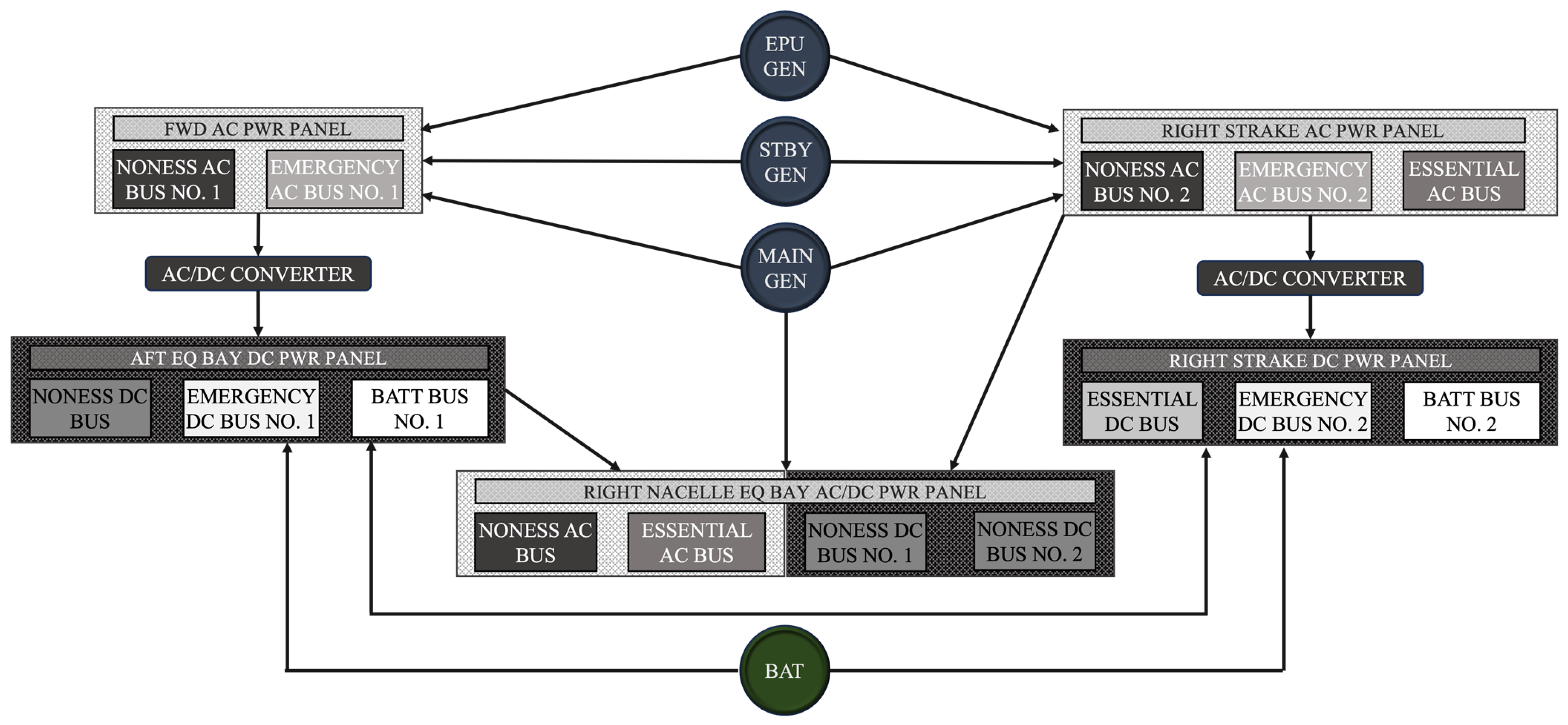
The electrical power system of the F-16 aircraft provides 115 VAC and 28 VDC. System architecture, including the bus configurations and their integration with other system components, is summarized in
Figure 3. The aircraft is equipped with three different generators that activate depending on the operational conditions. The main generator, rated at 60 kVA, serves as the primary power source under normal operating conditions, supplying to all buses: non-essential, essential, and emergency buses. In the case of a main generator failure, the 10 kVA standby generator is activated to maintain power supply for the essential and emergency buses. If both the main generator and standby generator fail, the 5 kVA Emergency Power Unit (EPU) generator comes online to energize the emergency bus only. While the main generator and standby generator are mechanically driven by the Accessory Drive Gearbox, which is connected to the aircraft engine, the EPU Generator is powered independently by the Emergency Power Unit. This hierarchical arrangement ensures redundancy and reliability in the aircraft’s electrical power system.
DC power in the aircraft is provided in two different ways. Primarily, under normal operating conditions, the output of 115 VAC sources is converted to 28 VDC with AC/DC converters. In the event of an emergency, the aircraft battery is used to ensure the required DC power. The bus structure of the DC side is the same as the AC side, but additionally includes a battery bus. Furthermore, the relationship and hierarchy between the buses and generators on the DC side are also parallel with the AC side.
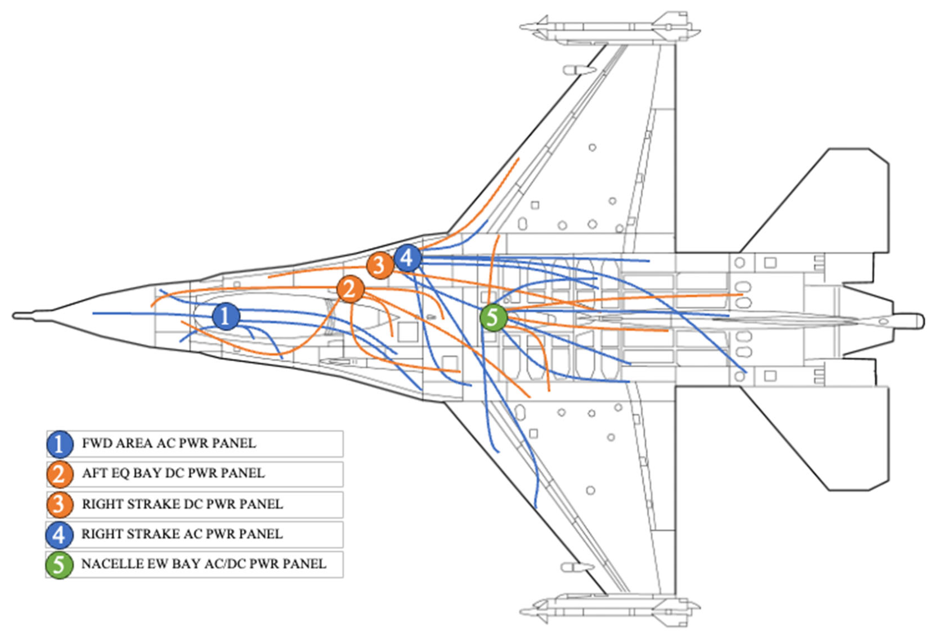
The electrical power distribution system comprises a total of five units, which are responsible for the distribution of power to the loads on the secondary side, as illustrated in
Figure 4. Interconnections and control between the buses are facilitated by contactors within the distribution units.
5.2. Application of E2P2S
A test of the E2P2S algorithm on a small example system is presented in the previous parts. In this section, the algorithm is examined through a case study, specifically focusing on the F-16 Block 50 aircraft, which is selected as the baseline platform. The most critical issue is providing the algorithm with a comprehensive set of inputs, such as the power consumption of the loads, the cable lengths between loads and distribution units, and constraints like redundancy requirements. Therefore, a detailed and extensive preparation is required. Due to the large size of datasets, they are not shared in the study; instead, the focus is placed directly on analyzing the results.
Using five distribution units and approximately 200 loads, a total of 21,000 different system topologies can theoretically be generated, having neglected all constraints. For each load, 32 different connection patterns can be formed across the five distribution units. When multiplied by the total number of loads, the total number of possible combinations becomes enormously large, as described in Equation (1). Moreover, constraints increase the complexity of the solution space. Under these conditions, identifying the configuration that provides the minimum system weight becomes impractical through conventional methods.
The importance of the E2P2S algorithm becomes obvious at this point. By running the model developed in CPLEX, the optimal results are rapidly obtained. The solution of the E2P2S algorithm for the F-16 Block 50 aircraft was completed in less than one second using CPLEX, indicating its high suitability for integration into the design phase. This allows for the rapid evaluation of multiple design alternatives, leading to the identification of the configuration that minimizes the weight of the secondary power distribution system. Moreover, the approach can be effectively utilized in a wide range of studies, ranging from system architecture development to the installation of electrical power system components on the aircraft.
To obtain meaningful outcomes, different scenarios are evaluated. Accordingly, to capture the worst-case condition, the heaviest system configuration—considering all constraints—is computed, resulting in a total system weight of 43,328 g. This value is the highest weight that can be achieved with the consideration of constraints. Total system weight with the existing aircraft configuration is calculated as 36,566 g. Keeping the same constraints, the optimization process is used to identify the most feasible configuration, which is found to be 30,350 g. These results indicate that E2P2S contributed to a weight reduction of up to 29% for the worst-case condition and 17% for the existing aircraft configuration. Considering the significant impact of the weight factor in aircraft, a reduction of 6 kg is seen to provide a highly important improvement. It is also found that 102 of 195 distribution unit output channels from the existing aircraft configuration are changed to other channels at the end of the optimization process. Additionally, neglecting constraint 5, the ±10% power difference limit of the distribution units, the system weight could theoretically be reduced further to 29,602 g. This demonstrates that the impact of each parameter in the system design can be rapidly assessed, enabling the development of system requirements. Thanks to the E2P2S algorithm, the effects of adding or removing constraints, modifying parameters, or changing distribution unit configurations can be easily and efficiently evaluated.
In order to provide a better evaluation of the impact of E2P2S, previous studies in the literature with a focus on weight reduction have been reviewed. In an optimization study conducted for a fuel cell-powered aircraft, it was shown with a case study that improvements in PEMFC technology led to a 10% reduction in system weight [
46]. An optimization study of the MEA electrical power system architecture, conducted with Mixed Integer Linear Programming, presented a 23% reduction in system weight [
47]. An investigation on the Cirrus SR-22 aircraft explored optimization across different hybrid configurations, showing achievable weight reductions in the range of 1–10% [
48]. Therefore, previous studies related to aircraft electrical system optimization show that the contribution of E2P2S with 17% reduction proves the importance of the algorithm.
6. Conclusions
The aviation industry is undergoing a transformation driven by environmental concerns and energy efficiency. As a result, the design of next-generation aircraft electrical power systems has become a high-priority research area, where optimization studies play a critical role. Reducing system weight is considered one of the primary goals, as it plays a key role in enhancing overall efficiency and performance. Total wiring constitutes about 2–3% of the total aircraft weight, within which secondary distribution cables have a large share, representing around 40–60% of the total wiring weight. These cables, which establish connections between distribution units and electrical loads, present a crucial optimization challenge known as the Load Allocation Problem (LAP), which determines the optimal assignment of loads and distribution units.
This study introduced an optimization algorithm called E2P2S, specifically developed for the secondary distribution architecture of aircraft electrical power systems, formulated to minimize total system weight subject to defined constraints. While extensive research has been conducted on weight reduction for aircraft electrical systems, E2P2S has developed to address the gap in secondary power distribution optimization. E2P2S is implemented by using CPLEX software, and its effectiveness is evaluated through a case study, F-16 Block 50. The case study shows that E2P2S provides a 17% decrease in cable weight for secondary distribution, demonstrating the algorithm’s benefit.
Aircraft electrical power systems contain numerous opportunities for further optimization. Future research may include expanding the objective functions for secondary distribution, optimizing the number, size, and placement of distribution units, and integrating the primary distribution into the optimization framework. As optimization studies on the secondary electrical power distribution systems in aircraft continue rapidly, closing the research gaps is crucial for the development of new-generation aircraft.