1. Introduction
Increasingly research efforts are focused on the development of a hybrid shipboard Microgrid (SMG) due to the extensive penetration of alternating current (AC) and direct
current (DC) renewable systems. Hybrid shipboard microgrids (SMGs) can be shared for more efficacious operations because AC and DC can function together. Numerous mathematical models and analysis techniques must be evaluated and upgraded, as the microgrid concept signifies a paradigm shift in conventional power systems [
1]. Microgrids can yield energy from photo-voltaic (PV) RES. Power electronics inverters link these sources to a synchronous grid via variable frequency AC power or DC power. Syncing, power balance, voltage regulation, and load sharing in the network are made possible through these inverters. A range of control strategies has been projected to overcome such challenges and have been merged into a hierarchical control architecture to yield three levels in this hierarchy [
2].
Alternate energy sources and energy storage technologies should be considered for short-range ships and seaports. Ships propelled by fossil fuels emit pollutants into the air as they dock at ports, endangering the people who live nearby. Another method of reducing carbon emissions from shipping ports is addressed by supplying ships with electricity from shore power linked to the power network or cold ironing. However, cold ironing reduces ships’ emissions while at the dock, raising the demand for electricity on the power network. Additionally, developing technology for the electrification of port facilities and other expenditures associated with delivering electricity to seaports far from the grid network would make this option impractical. As an alternative, hybrid SMGs enables mobile cold-ironing capabilities by having local energy production from RES on ships and the flexibility to exchange electricity with other ships in port. This strategy might be implemented by forming a public-private partnership or offering benefits to shipowners of battery-powered yachts and ferries [
3]. As part of the blue growth (Europe’s goal), it will assist in reducing emissions from the seaport transportation industry and develop a sustainable approach, including ports and shipowners.
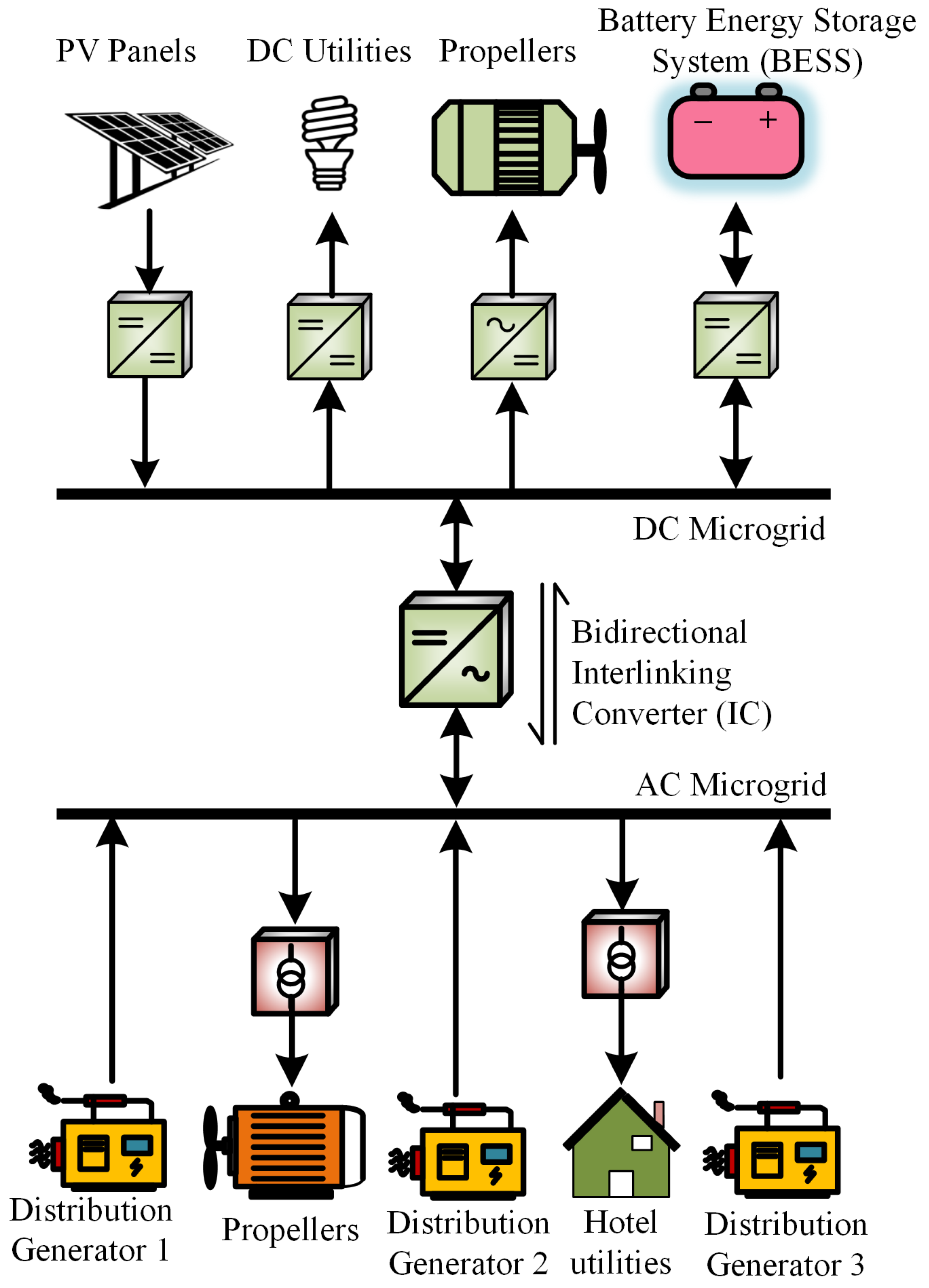
The hybrid SMG offers a comprehensive answer to the energy problems, such as the compatibility of sources and loads. It can combine DC and AC electrical sources and loads with a few conversion steps. As seen in
Figure 1, the interconnecting inverter allows the transfer of power between the DC and AC microgrid (MG) and the primary utility by the use of a suitable control scheme. Thus, the autonomous operational capacity of a hybrid shipboard MG is much greater than separately DC or AC type MG. Control of the MG may be centralized or decentralized.
The primary objective of [
4] is to validate the solar energy’s maximum power during various operating situations while applying modern management to the grid-connected inverter side in preparation for the H
∞ controller. The following are some specific ways that the study presented: (1) To regulate the inverter functioning of a grid-tied Photovoltaic system, a technologically advanced control based on an H
∞ controller is created, (2) A fair comparison of the Perturb-Observe (P&O) and Incremental Conductance (InC) maximum power point tracking (MPPT) approaches used by the traditional PI controller and the H
∞ controller under varying photovoltaic circumstances are shown.
Grid-linked hybrid renewable energy systems seldom use fractional order controllers to improve PV generation. The authors in [
5] presented the literature on the development of a fractional order proportional integral controller. By comparing the designed fractional order proportional integral effectiveness to that of traditional and integral order PI and variable structure integral controllers by taking into account the system’s variable conditions again for photovoltaic and wind turbine.
The research in [
6] discussed a multi-agent distributed energy management system for DC shipboard in order to regulate voltage and share DG power cost-effectively to reduce fuel consumption. For this purpose, programmable logic controllers (PLCs) with interconnected coordination are used to implement the DC approximation of the industrial Rolls-Royce system. The suggested approach was validated in a real-world control environment under constraints of computational resources, constrained network bandwidth, and ineffective communication routes, leading to engineering disciplines. A controller hardware in the loop (HIL) investigation was used to verify the suggested control approach for platform supply vessel (PSV) type Shipboard Power Systems (SPS), which provide a real-world implementation for distributed systems. OPAL-RT simulates the SPS architecture and major processors in a real-time environment.
A distributed hierarchical control technique is presented for islanded Microgrids. The control system is designed to accomplish a number of functions. The goal of secondary control is to maintain the voltage and frequency at reference levels under arbitrary power sharing. Apart from that, the tertiary control goal is to improve grid functioning. Furthermore, the suggested multi-agent system agent design can be implemented under practical circumstances. Each agent is made to perform two concurrent secondary control and tertiary control processes by sharing data over the communication system. In HIL implementation, study [
7] performs stability testing using a cyber-physical model for practical validation. The hardware agents may function asynchronously inside a simple communication system replicating how the multi-agent system functions in the real world.
The implementation of an H
∞ loop shaping controller is discussed in [
8]. In this work, gains can be improved using particle swarm optimization, Genetic Algorithm, and H
∞ droop control methods. The comparative performance of the three controllers is shown. Furthermore, the random load dynamics, stochastic fluctuation of wind, and system uncertainties are to examine and regulated. The standardized secondary decomposition approach represents all nonlinear uncertainties in the system. Additionally, possibility of using superconducting magnetic energy storage or ultra-capacitor to balance power and stabilize a poor hybrid DG infrastructure is discussed.
The authors in [
9] presents the electric ship power management strategy by considering the optimum dispatch issue. Here, Model Predictive Controller (MPC) is employed to achieve optimal power delivery. It is believed that the prediction of shiploads can be possible. As a result, the goal of suggested method is to optimize power production over a certain period of time. Two DGs and a propulsion load are a major part of the system.
Study [
10] suggest a time-varying, smooth-moving linear sliding surface. The least disturbance trajectory is the requirement for a smooth trajectory. It drives a mass point along a trajectory while limiting parametric variations. As a result, the trajectory becomes uniform, and energy utilization is decreased. In conclusion, the error monitoring response of the suggested method is better than that of traditional techniques. Furthermore, the suggested method may decrease energy usage and convergence time compared to existing approaches.
SMC is a nonlinear type of controller which is robust to parametric variations. The systematic procedure of the proposed method offers a direct result for power management and control. The SMC method has many benefits, for instance, robustness against matched external disturbances and unstable parameter variations. Furthermore, the SMC method is applied to answer the nonlinear tracking systems with a continuously switching methodology. It is considered that the SMC is a robust type of control design due to its dominance in the variations of the system’s dynamics. On the other hand, the H
∞ controller is a linear type of controller which is also created to be robust to system uncertainties, random wind influence, and load changes [
8]. However, theH
∞ controller has less error in voltage of load and frequency compared to the Linear Quadratic Regulator (LQR), or MPC method [
9]. Moreover, the performance of the frequency variations is enhanced by considering the H
∞ control scheme compared to the LQR or MPC method. Hence, we used SMC based controller, which is robust in nature and able to provide efficient power management and operation functionalities [
11].
The optimized PID controller scalability factors are demonstrated in [
12] by using the cutting-edge lightning attachment procedure optimization (LAPO) optimization technique. Furthermore, investigation and evaluation with the traditional particle swarm optimization (PSO) were the outcomes that were produced. The effectiveness of the designed controllers is examined while altering the dynamics of load.
Circumstances of the system’s solar panels and wind turbines. The proposed LAPO algorithms outperform the traditional PSO. All the data was collected under various wind turbine and solar sunlight functional circumstances [
13]. The wind speed estimation (WSE) approach is used in this study to offer an efficient and practical control system for achieving MPPT from a doubly fed induction generator (DFIG) during varying wind situations. The functional and mathematical analysis of the suggested technique significantly contributes to this research. Additionally, to demonstrate the effectiveness of the proposed system, a complete comparison is presented between the implementation of the suggested control technique and the PSO approach.
In order to improve the efficiency of energy generation, the PV system enables it to function successfully with SMGs. The research [
4] proposes two strategies for MPPT through DC/DC converter. P&O and InC of the solution are the two MPPT methods. When using the two MPPT approaches, the variations in temperatures and solar radiation are considered. Additionally, the system’s efficiency under erratic variations in solar energy was examined. At the three-phase rectifier, the authors employed PI and H
∞ controllers. Including the two MPPT approaches, the maximum power at each converter controller is contrasted. The usefulness of the designed controllers and MPPT methodologies is shown by comparing the acquired findings with several previously published research. The findings indicate that the InC approach is more reliable in the case of MPPT through P&O and InC techniques combined with the proposed controller. As a result, the power generated achieved is well-coordinated with the standards one as opposed to the MPP P&O method, which shows a 7% error.
In order to create a stable voltage controller for buck DC/DC converters, research [
14] suggests combining the end attractor technique with an improved ranging law-based Fast Terminal Synergetic Controller (FTSC). The suggested method will get beyond the problems with classic Synergetic Controllers’ unlimited time resolution and the chattering phenomenon limitation of current SMC. The improved reaching law and the FTSC method work together to achieve accurate voltage tracking and finite-time resolution in this method. Here, the uncertain converter nonlinear behaviors caused by variations in the input voltage and loads are approximated by using a fuzzy neural network (FNN) design. In order to react to shifts in the system’s uncertainty, the weighting of the FNN is adaptively changed in real time. As a result, it increases the resilience of the system. Furthermore, real-time architecture evaluations and thorough comparisons with an existing FTSC with the proposed controller. The suggested method is implemented on dSPACE ds1103 hardware.
The DC-DC converter and DC-AC converters are used to connect the PV system to the microgrid. The study intends to improve how PV systems are integrated into the electrical grid by managing both the conversion and the converters. Moreover, adapting a reference PI (ARPI) regulator for the converter improves system efficiency by offering low voltage ride-through (LVRT) capabilities and reducing variations in PV-produced power under changing environmental circumstances. While the converter is utilized to implement the PV scheme P&O computation MPPT under diverse environmental circumstances. To evaluate the success of the suggested method, a comparison between the application performance utilizing the suggested adaptive reference PI (ARPI) and an ideal PI controller improved via harmony search (HS) is proposed in [
15].
Additionally, the Interlinking Converter (IC) has frequency-voltage droop control that considers the secondary AC control effect. IC are indispensable components of SMG because they facilitate the controlled and stable transformation of energy between the AC and DC side [
16]. By considering the aforementioned literature reviews, traditional control strategies can be used to implement the DC SMGs. However, we are considering a hybrid AC/DC microgrid system for the SMGs where the nonlinear AC load and DC load are dynamically changing. Therefore, we proposed an SMC-based secondary controller which is robust to both AC-type and DC-type load variations on SMGs. Furthermore, nonlinear parametric uncertainties are taken into account.
The control scheme can be modified or improved in several novel AC/DC hybrid microgrids control arrangements.
We present a SMC based technique for droop control in AC/DC hybrid SMGs under different operating conditions, employing a bidirectional control method of IC.
A robust loop controller with a power management strategy is anticipated that monitors voltage and frequency fluctuations in AC/DC SMGs using IC as a bidirectional power transmission module.
In this research study, we compare the performance characteristics of AC and DC secondary controls in hybrid microgrids for shipboard application.
A hierarchical primary and secondary controller is employed on ICs, which are used between AC and DC microgrids to mitigate non-linearities during power fluctuations.
Secondary controllers include PI controllers and SMCs. We compare the performance characteristics of secondary controller schemes.
The study in the research has been organized as follows.
Section 2 describes the problem formulation in which we elaborate modeling and design of the AC/DC SMG. In
Section 3, the proposed hierarchical control scheme for the SMG system has been addressed. The simulation results are elucidated in
Section 4 and conclusion and future work are outlined in
Section 5, respectively.
2. Problem Formulation
The microgrid system can be utilized as the next generation of conventional power systems, which focuses on bidirectional power flow and information exchange [
17]. Apart from that, the conventional power grid consists of electricity generation, transmission, distribution, control centers, and consumers [
18]. Key advantages of a smart grid include two-way coordination services and the capacity to make greater use of alternative energy sources [
19]. Using intelligent microgrid technology, smaller regions can operate on islands or be connected to the grid as part of the larger power system. Microgrids with intelligent controls and tracking offer consumers improved service and control. The main connection point of common coupling (PCC) links the microgrid to the electrical network in grid-connected mode. The microgrid operates autonomously and independently meets control requirements [
20]. Microgrids are challenging to control because multilevel control techniques are required to meet voltage and frequency security restrictions, among other technical constraints, especially in the isolated mode.
Microgrids are classified as DC, AC, or hybrid AC/DC depending on the type of power transmission.
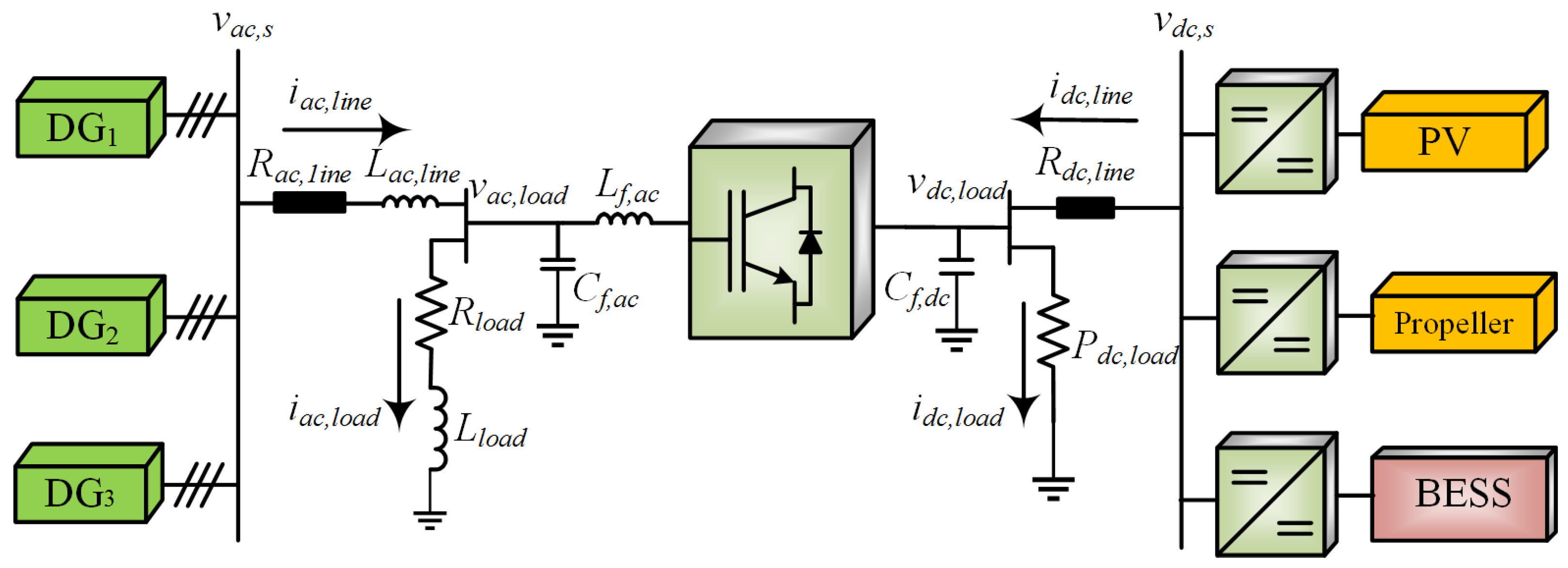
Figure 2 shows the single line diagram (SLD) of a hybrid SMG structure [
21,
22]. Three distribution generators (DGs) that are DG
, DG
, and DG
are considered to be connected to the AC bus
where an AC local load
and
are provided. On other PV panels, and storage systems are connected with the DC bus
which provides source power for the attached DC load
. Each DC source is connected with an individual DC/DC converter to regulate the voltage. There is an interlinking power converter between both AC and DC buses, including transmission line lumped impedance that are
,
, and
. The AC load type can be a static or dynamic load, but DC is considered only a static resistive load. The IC facilitates bidirectional power flow and management.
A boost converter is connected to the load to ensure that the voltage stays stable under unlike conditions. Three-phase
filter is determined by
and
. The cutoff frequency of
filters can be determined using
. The coupling capacitor
is used for rectification, and the IC ensures the bidirectional flow of power between the two microgrids. If a DC source produces a constant amount of power or if it uses renewable energy resources at the maximum power point, it is said that its operating conditions are DC [
23]. The amount of power consumed exclusively swings upon the amount of power being consumed by the consumer during a DC load. It indicates that there is a possibility when DC power consumption attains beyond the dispatchable power. In this case, the AC power source is essential to compensate for the DC demand power. Likewise, when the AC load increases, the power consumption will be greater than the AC supply, so power will have to be recovered from the DC source side to meet the required demand.
In this research, we analytically presented the robustness of our proposed hierarchical control design for the hybrid Shipboard Microgrid (SMG) system containing various DG and PV-based RES integrations for a shipboard microgrid. The performance comparison of the conventional PI vs. SMC-based control design is validated with simulation tests under different static and dynamical load conditions for both AC and DC types of loads on the shipboard microgrid. We further considered multi-DG and RES integrations into our system to prove our design’s robustness against noise and unwanted faulty load conditions. The complete system stability analysis and designing of the control law are performed. Furthermore, mathematical derivations and simulation results prove the robustness of the proposed hierarchical control architecture. The DC side of the voltage source converter (VSC) comprises a DC-link capacitor. The microgrid may have a single or several power sources. However, the control techniques may be adapted for three-phase microgrids. Therefore, filter harmonics such as Total Harmonic Distortion (THD) must also be considered, although they are not the topic of this work but can be extended into future works.
2.1. AC Microgrid Modeling
Consider a static
and
are linked to the AC microgrid. The load is powered by AC type DGs. We can determine dynamic equations for the AC microgrid using Kirchhoff’s Voltage Law (KVL) on the AC source side. In the study, a two-level hierarchical control system for DG units will be presented, including both droop-based primary and secondary controls for restoring voltage and frequency parameters [
24]. The AC source voltage
is a summation of the attached AC load voltage and the voltage across transmission line impedance. From
Figure 2, the source side equation can be given as
where voltage across line impedance is the rate of change of line inductance.
so, (
1) can be written as
By rearranging (
3), we get
Now, AC load side equation is the summation of voltages across load impedance.
where
so, (
5) can be written as
By rearranging (
7), we get
The
state space model for (
4) and (
8) of AC network can be given as
2.2. DC Microgrid Modeling
KVL can be applied to the DC microgrid system equation at the DC source side. In the case of a DC source that is linked to a battery that provides constant voltage, a DC source would be connected to such a battery. Moreover, DC load is a constant power load [
25]. According to KVL at the DC MG, DC source voltage is the summation of load voltage and potential difference across the line loss.
For constant power load,
will remain unchanged which can be expressed as.
Electric power production can be obtained by using renewable energy sources, which, in turn, reduces the number of DG units required. In other words, the efficiency to transmitting power to the consuming power system exponentially increases throughout the year. The vast majority of renewable energy sources are fitted with battery energy storage systems (BESS) owing to the nature of these resources. Employing storage units i.e., batteries and fuel cells results in a cleaner, more reliable power-producing unit [
26].
2.3. Battery Energy Storage Systems
A microgrid is a collection of autonomously operating generating sources, energy storage devices, and loads [
27,
28]. Specifically, DC microgrids have the benefit of having fewer power conversion steps when incorporating current DC-based sources (e.g., PV, and batteries). In addition, it has been demonstrated that DC microgrids are an order of magnitude more reliable than AC microgrids [
29,
30]. A fundamental load-sharing control mechanism is required amongst microgrid sources for autonomous operation. In DC microgrids, decentralized
droop control is the conventional principal control approach.
droop management has various difficulties when used to manage load sharing amongst BESS [
31]. As a result of voltage dips across the microgrid lines, each battery will function at a unique charging/discharging current. This will generate a divergence in the state of charge (SoC) levels of the BESS.
2.4. Solar Energy Modeling
Maghraby et al. [
32] proposed that the area evaluated by the solar panels and the number of battery banks should be evaluated based on the anticipated demand in order to maximize the size of the clean energy-producing units. Using fuzzy optimization approaches, Terra et al. [
33] could obtain the greatest potential power from a hybrid renewable energy system comprised of solar panels and wind turbines. This HRE microgrid’s steady and continuous electricity supply was determined, in part, by the cost of solar panels and the surface angle of these panels. Habib et al. [
34] have constructed and simulated a microgrid powered by renewable energy. Researchers also adjusted factors such as battery bank longevity, efficiency, and longevity of the solar panels in addition to inclination and latitude of the panels, MPP, and longevity of the battery banks. Koutroulis et al. [
35] underscored and presented an ideal renewable energy generating scheme in which the size and inclination angle of the solar panel was maximized. A year of hourly climatic data was used to improve the energy storage source (ESS) based on the battery charge level and capacity. Borowy et al. [
36] developed an efficient scheme that can predict and obtain the optimum output power of the photovoltaic module, employing average temperature and solar radiation statistics. Zhou et al. [
37] presented a model that predicts the performance of a photovoltaic array in relation to external temperature and solar irradiance. Yang et al. [
38] established an effective model for maximizing solar panel power production. Furthermore, their proposal explored the use of MPPT controllers. A study was conducted to determine whether snow shading, covering, and wire loss should be considered.
2.5. Incremental Conductance MPPT Algorithm
A modified InC technique for efficient and precise maximum power point tracking has been suggested in [
39]. Complete comparison research was done to evaluate the suggested technique’s characteristics against traditional methodologies. The suggested model effectively overcomes efficiency concerns and substantially increases production. This study anticipates the variable step size of the incremental conductance (InC)-based MPPT approach by combining a completely genetic algorithm (GA) with the Proportional Integral Differentiator (PID). After comparing the system to the P&O MPPT, it was shown to be more effective at finding the global maximums (GM) for rapidly changing irradiance due to the regulator’s use of GA-based criteria.
The study conducted in [
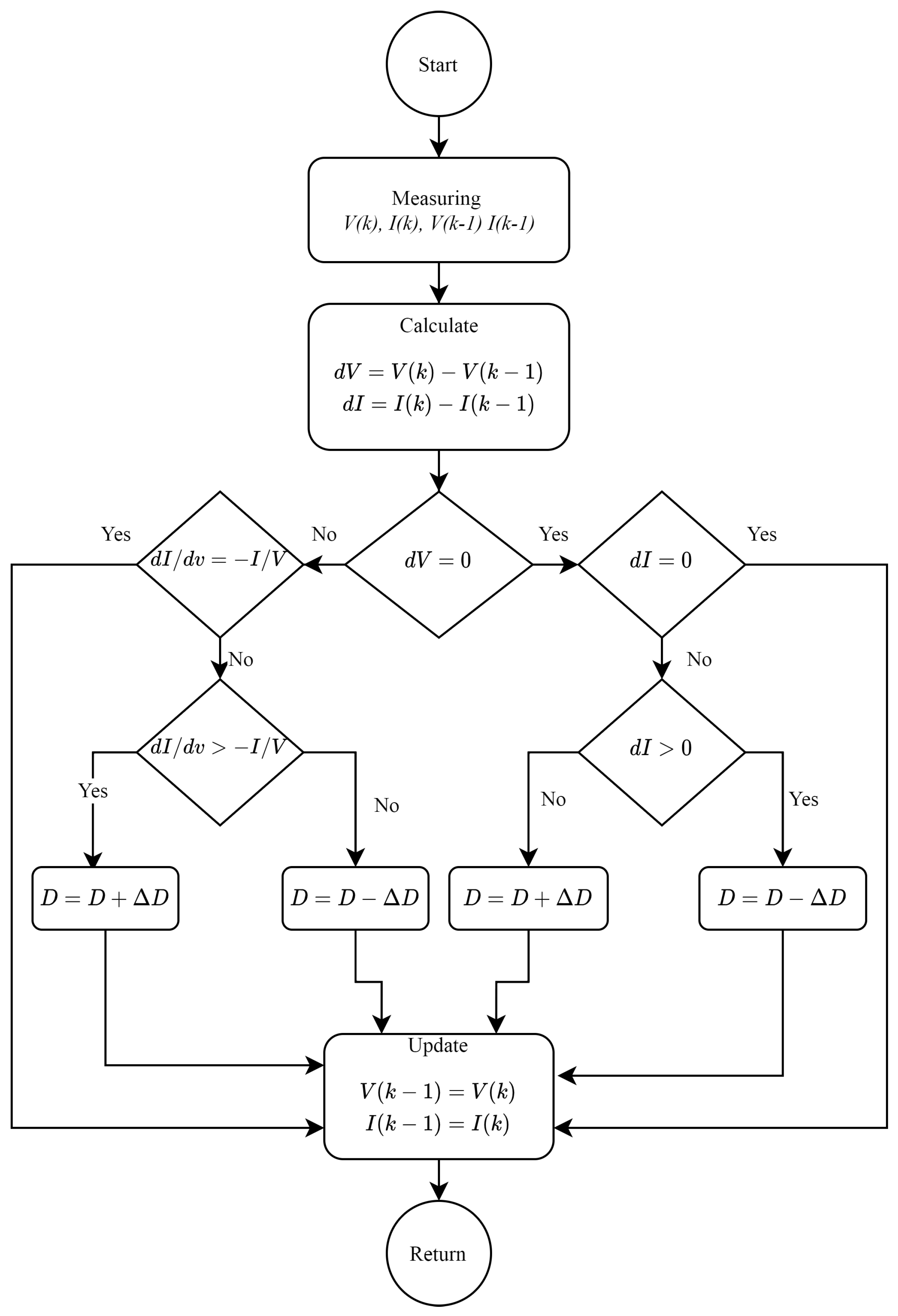
40] aims at developing a method for MPPT that integrates fuzzy logic and artificial neural networks (ANN) with adaptive radial basis function (RBF). The proposed method uses DC-DC boost converter coupled to a resistive load and PV system. In terms of energy conversion efficiency, the conventional P&O methods are exceeded by the new technique, namely InC. The flow chart of InC is depicted in
Figure 3.
A research study in [
41] alters a P&O MPPT algorithm and applies fuzzy logic-based variable step size features to circumvent the limits of the conventional MPPT P&O tracking approach. As a result, the system’s stability is enhanced by dampening the transient regime. The researchers employ an indoor PV source simulation for testing purposes. DSpace has supplied the PV source with a regular solar panel, a DC power supply, a DC-DC converter, and an MPPT regulator.
Table 1 presents the parameters of the proposed Microgrid model.
The InC method is generally more accurate and efficient due to its ability to track rapidly changing irradiation. By this algorithm, the maximum power operating point of the module can be calculated in real-time using conductance and InC [
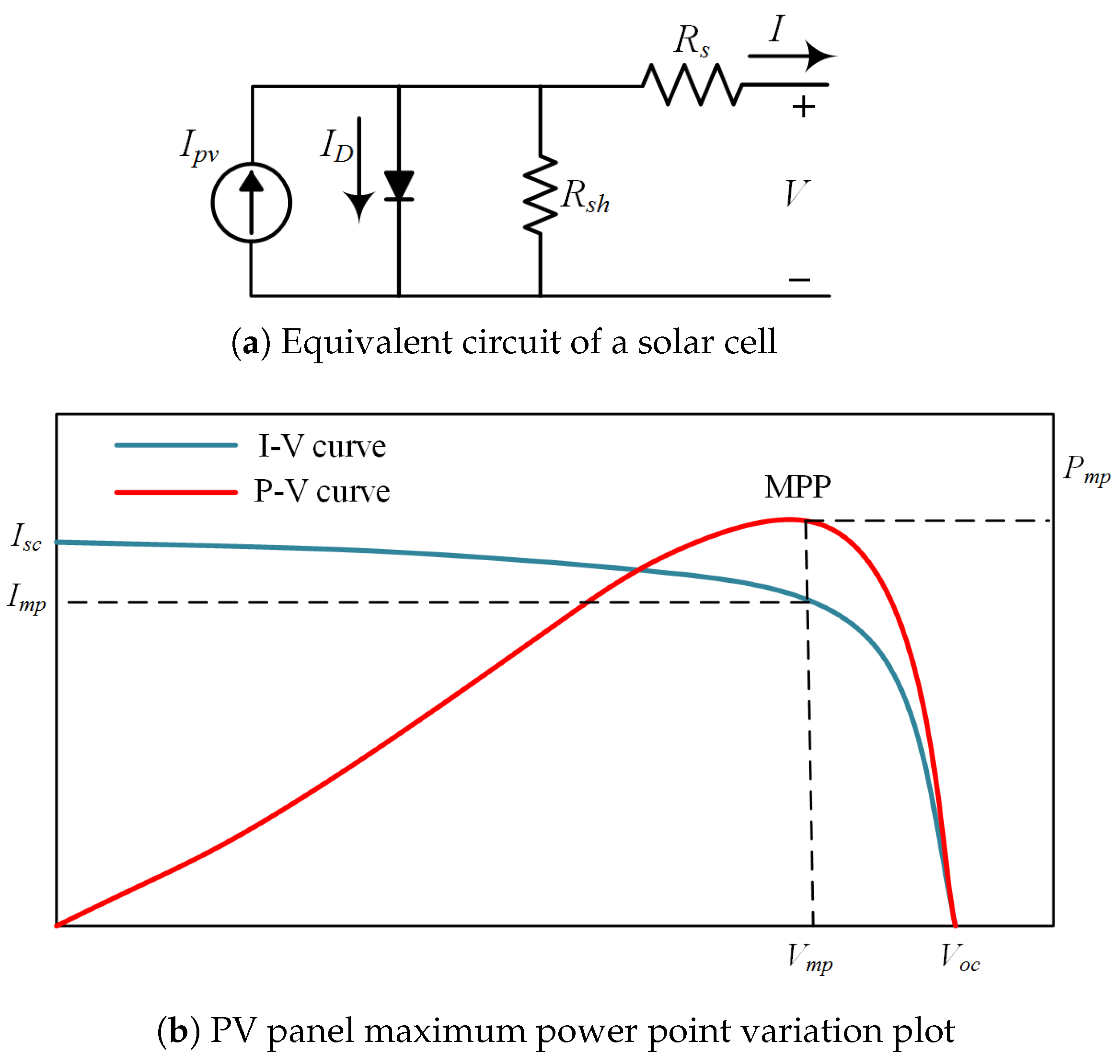
42]. The equivalent circuit of a solar cell model is shown in
Figure 4a. The MPPT occurs when the slope of the
curve is zero, which is shown in
Figure 4b. The following equations can represent it.
Left of maximum power point
Right of maximum power point
Differentiating
, we get the following expression,
at maximum power point
at maximum power point
3. Controller Design
Primary and secondary controls function on a short operating time scale, directly influencing the steady-state solution. Ideally, both primary and secondary controls ought to be operational in the DC/AC microgrid modeling to attain reliable steady-state analysis. In order to function hybrid SMG systems and control load distribution between DC and AC power sources, a stable and suitable power management technique is required. Controlling power distribution in DC and AC microgrids has an interesting ambit of contemporary research ideas, and there have been fewer efforts in power management between AC and DC power generations for hybrid systems up until now. Power-sharing control in microgrids has been implemented using a dependable power-sharing approach inspired by synchronous alternator governors [
43]. The frequency droop characteristics require the cooperation of multiple converters to determine the corresponding reference power. Using the drooping slope principle, load balancing includes all control modules.
Figure 5 shows the hierarchical control structure. Here, we can see three control levels that have their individual responsibility. First, distributed control is considered at the primary level. The converter has a separate current loop and a voltage loop controller. Additionally, a DC current loop control is used as a droop controller to achieve power-sharing. On the other hand, the secondary level of control is where the loop control no longer causes DC voltage fluctuations on the shipboard microgrid. Current and voltage droops must be traded off in order to implement current loops controlled converters. The secondary PI controller restores the voltage fluctuations and upholds the current loop. For the centralized control system, primary and secondary control are used on the DC-side and operate independently. Similarly, the tertiary control level PI controller is employed for coordination to regulate the power transfer among the several AC and DC microgrids.
The benefits of centralized control systems are as follows:
the primary objectives are recognized and achieved
they can provide global optimal decisions/solutions.
their synchronization with the primary utility is simple, and they can be run online efficiently.
Decentralized control systems, on the other hand, have the following benefits:
they are suitable for rapidly changing infrastructures
they can be easily expanded due to their high plug-and-play capabilities.
their reliability is high.
their communication and computational costs are relatively low.
Numerous control algorithms, such as
[
44], LQR [
45], sliding mode [
46], model predictive control [
47], and artificial intelligence (AI) approaches, such as fuzzy logic [
48,
49], neural networks [
50], and genetic programming [
51], have produced both centralized and decentralized controllers.
There is a natural evolution from this level of control to secondary control. Secondary control intends to eliminate the deviations mentioned above in local voltage and global frequency. High-voltage distribution and transmission networks have broadly studied centralized control systems. These strategies have also been adapted to microgrids. The term secondary control has been enlarged to contain additional objectives: harmonic compensation, reactive power-sharing, and voltage unbalance [
52]. Current energy prices and market conditions decide global economic dispatch over the network at the tertiary level of control.
3.1. Droop Control
Droop control plays a significant role in primary control design, and the primary controller is responsible for the voltage and frequency droops. Therefore, a good primary controller can provide power regulation and flow on both sides of the grid. We used SMC based droop controller to overcome voltage and frequency dips during grid changeover or load variations. From the perspective of the power system, two kinds of control systems are implemented. That is centralized and decentralized [
12]. A centralized control needs the connection between the central controller and the local controller of each DG unit. Depending on the acquired data from the local controller, control signals are decided at the central controller and relayed back to the local controller for operation. However, each DG unit is controlled by the local controller under a decentralized control, which does not need contact with other units. In decentralized control, the local controllers are oblivious to system-wide errors. Primary control provides the fastest reaction time and does not need communication when employed in the decentralized system. However, it needs communication when utilized in centralized control, distributed control, and master-slave control [
13]. The responsibility of primary control is regulating frequency and voltage at the inner loop of control. Due to its fastest reaction time, it also considers good care for the islanding detection, power balance, and output power regulation of DGs.
Few scientists have examined the power-sharing associated with hybrid shipboard microgrids operating in grid-connected or islanded mode. Active power and frequency (
) and reactive power and voltage (
) are often used for sharing AC microgrid realization. They are the characteristics of active and frequency (
) and reactive power and voltage (
). Regarding DC microgrids, it is advised to implement both current and voltage (
) and active power and voltage (
) drooping characteristics when DC microgrids are part of a hybrid microgrid. However, communication between two microgrids, i.e., hybrid microgrid and power-voltage (
) droop characteristics, is typically implemented. The correct quantity of active power must be exchanged between two microgrids via an interconnecting converter to extend active power sharing relevant to the sources of both microgrids, also known as proportionate active power sharing. Regarding this, the active reference power for the interlinking converter is determined by factoring in the frequency and voltage of the AC and DC microgrids to ensure the exchange of active power and the achievement of proportionate power-sharing [
43].
However, the droop-control-based power distribution technique has several drawbacks, also known as primary control in hierarchical control systems. Inaccurate sharing might occur, for instance, if the magnitude of microgrid bus voltage varies as a function of line impedances during the realization of droop characteristics. There have been several initiatives to eliminate or mitigate this mistake. Various remedial procedures have been implemented by injecting additional harmonic signals into the line. However, such intrusive approaches have the disadvantage of distorting line currents in order to accomplish reactive power-sharing activities enabling signals at predetermined times.
3.2. Modeling of Voltage Source Converter
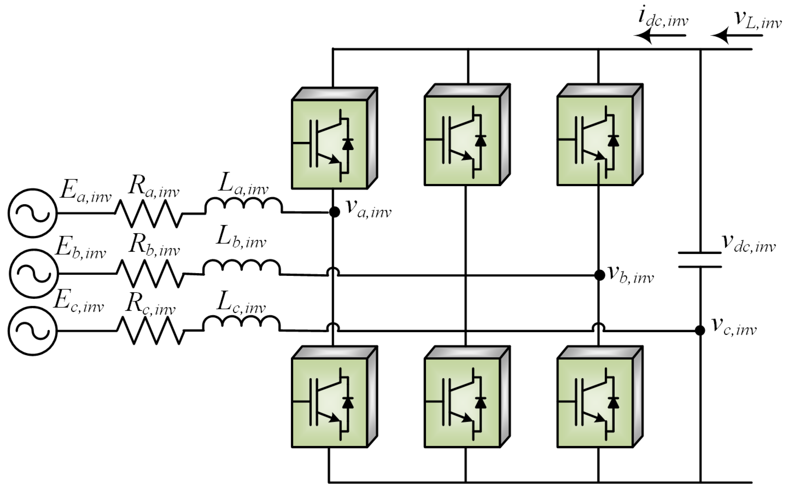
Figure 6 shows the three-phase VSC model for the hybrid shipboard MG. A two-level VSC system is used for the hierarchical control application. It comprises a dual-loop control based on a (
) loop, including an inner current loop and an outer voltage loop, whereas the secondary controller comprises a PI controller for restoring voltage [
53]. A current loop-based (
) loop can also be used to control the primary layer. Inverter terminal voltage
can be given as
Here inverter terminal voltage
is the summation of inverter transient voltage
and the rate of change of inverter line impedance. We are providing three-phase voltage
,
, and
on the VSC. So,
denotes a three-phase root mean square (RMS) voltage that will be received directly from the AC bus or through a three-phase transformer rather than using any double voltage capacitor. In both cases, the RMS voltage at the
will remain stable/constant after the transits. There exist an LC filter network in between AC bus and load. However, filter design is not in the scope of this work. Therefore, we considered it as constant in our expressions.
Applying
-transformation of three phase currents.
and
The state space model of (
24) and (
25) can be represent as
The leading principal minor of the coefficient matrix
A is negative definite, which implies that the system will be asymptotically stable for all time. Considering default initial values and inputs to zero, we get.
Let us choose a lyapunov function candidate as
By substituting
and
, we get
By simplifying, we get a negative semidefinite function, which can be expressed as,
or
Hence, it should guarantee stability of the system.
3.3. Proposed Secondary Controller Design and Analysis
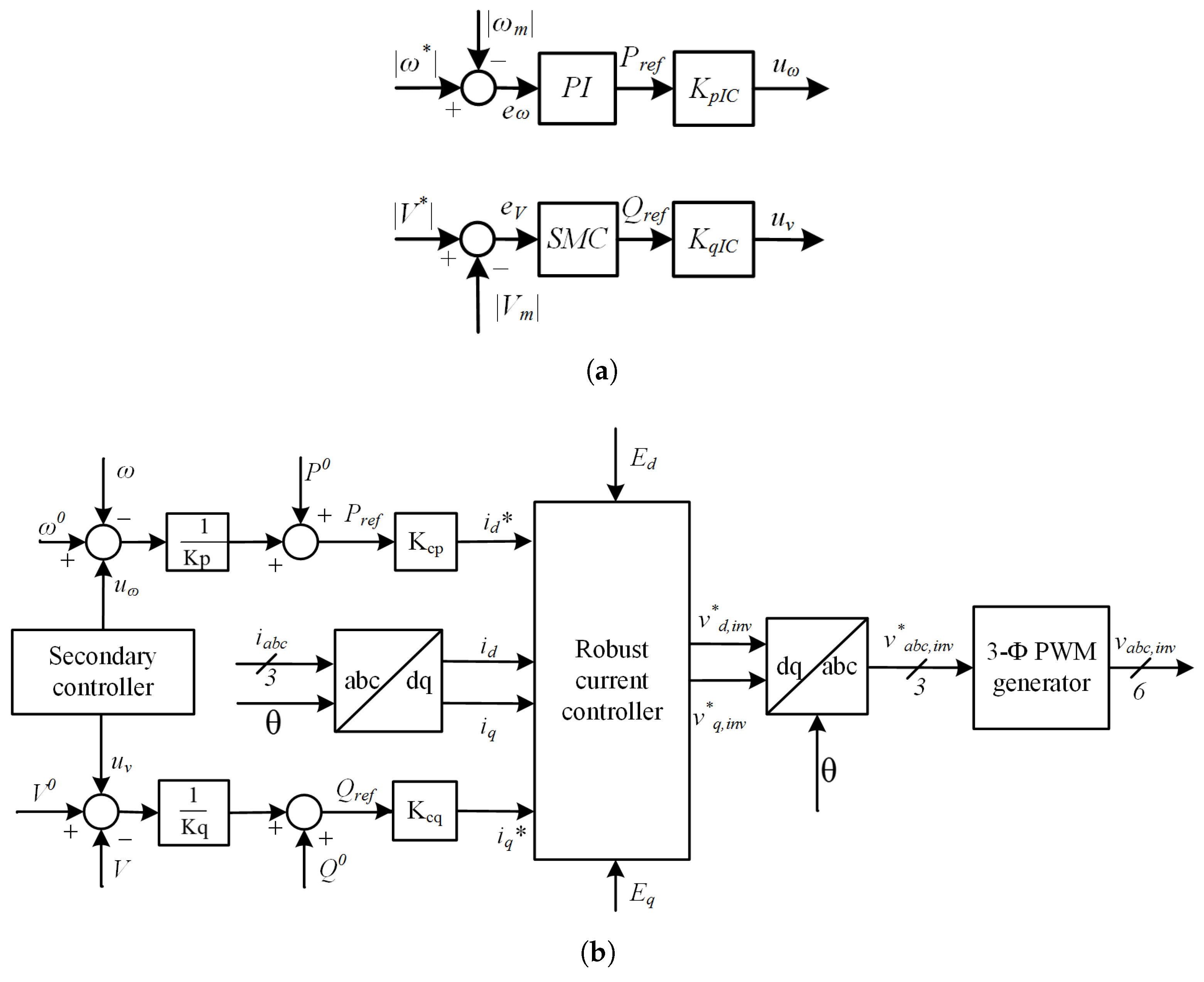
Figure 7a shows the proposed secondary controller design. Here, we employed a robust SMC to provide a reference signal for the primary controller design. Since the primary controller is used to reduce the effect of voltage and frequency droops, the secondary controller will support the primary controllers to further incorporate robust synchronizations among the power grids. Furthermore, the secondary controller makes sure that the required amount of demand power is being provided to load in any case. The secondary controller monitors the hybrid grid’s voltage and frequency variations as well as provides the reference control signal under drastic AC or DC load variations. The control signal
and
are processed with converter gain
and
, which generates heretical control signals
and
.
Figure 7b shows the conventional current controller scheme. The primary control design based on droop control regulates the voltage and frequency of the interlinking converter. Reference signals
and
generated by the proposed robust secondary controller are provided to the primary controller so that heretical control architecture is achieved. The droop controller will monitor the grid voltage and frequency and eventually produce Pulse Width Modulation (PWM) gating pulses
.
and
are normalized grid voltages. The robust current controller will produce
inverter signals, which further process the park inverse transformation to generate a three-phase
inverter signal for the PWM generator. The proposed secondary control law can be given as
where
is the control signal,
is controller gain and
s is sliding surface under a small sliding manifold of
. hence, the control law in our case can be represented as
and
errors between output and reference can be given as
Here
and
are at the grid-connected AC load.
and
are reference currents. The sliding surface
s will be
Sliding surface
s derivative is
at constant reference value,
referring (
42)
Rearranging the terms,
simplified form can be given as
where
The condition for
to satisfy is
where
is a positive constant. Now, for the stability analysts of our proposed control, let us choose a Lyapunov function candidate as
Chattering can be reduced by choosing
s as,
where
is a very small positive value. The closed-loop control law equation will be
Substituting (
55) into (
53), we get
or
where
Since
is a positive constant, we have
Now, by substituting values of in (
59) into (
58), we get
Equation (
63) investigated that the proposed controller will be a robust stabilizing controller that satisfies the condition in (
59).
Table 2 highlights parametric gains used to design the controller.
4. Simulation Results
The simulation was performed to compare the performance of the robust controller achieved by the controllers and , and we simulate a simplified model of a hybrid SMG under different test conditions. MATLAB/Simulink was used to implement the proposed control law for converters. The AC microgrid comprises of DGs unit with synchronous generator, excitation and governor control systems. PI controllers are often tuned with the Ziegler-Nichols rule when the plant dynamics are unknown.
Here, we used three different 1 kW active loads, 0.5 kVar inductive load connected in parallel with circuit breakers along with the transmission line lumped impedances. The operating frequency of the AC microgrid is 50 Hz. Subsequently, the AC microgrid is further tied with the three-phase distribution transformer and LC filter units so that it can deliver or receive power from the DC microgrid through the IC. Here, the IC is a 2-level VSC which facilitates flow power on both sides of the grid as per load requirements. On the other hand, a DC microgrid consists of DC sources such as BESS and PV solar panels and DC resistive loads transmission line resistance. DC MG’s nominal voltage is 550 volts, and it is connected to two different resistive loads via circuit breakers. DC load 1 is 1 kW and DC load 2 is kW. The purpose of the heretical controller is to take AC and DC line current information and generates references for the primary control, which eventually operates the IC. We used the Matlab/Simulink tool for the microgrid implementation and testing of our proposed controller
4.1. Case 1: Power Flow from DC to AC; Then AC to DC Side
Simulation work shows a performance comparison of conventional and proposed robust secondary control strategies for the hybrid SMG. We considered DC grid to AC grid transition at simulation time s. From time s, the AC grid is operating at DC source, so DC sources are providing power to both the DC load and AC loads. At time s, both DC and AC microgrids are switched over and now AC power is provided from AC sources to both AC and DC load from time 1.0 s s.
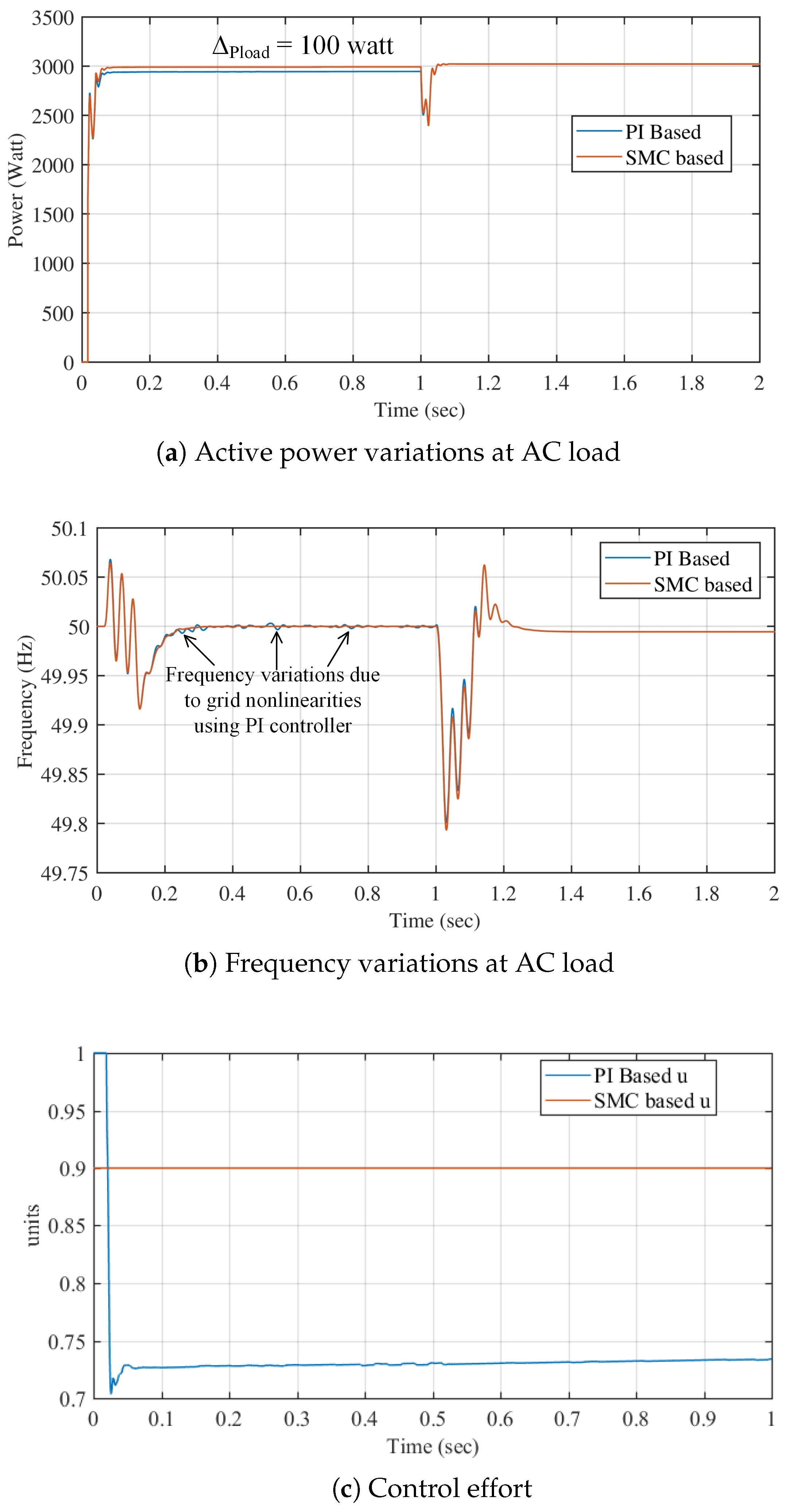
We consider that a 3 kW active power AC load is connected with the AC microgrid, and we are comparing the performance of two different control strategies in terms of successfully supplying the power to the AC load by validating different test cases. In case 1: we considered that power flows from the DC side to AC which means IC is operating as an inverter mode for the initial 1 s. For time 0 to 1 s, we can see that SMC-based (solid orange line) hierarchical control provides an accurate 3 kW power to the load, whereas the PI-based (solid blue line) hierarchical control provides kW power to the load, which makes 100 W difference in the same test scenario. This power loss will be magnified when we deal with utilities consuming high power and dynamic load variations, which is prominent in the simulation of case 3, case 4 and case 5 test scenarios. From 1 s to 2 s, the AC source circuit breaker was intact, and power to the AC load was directly provided by DGs. Therefore, no chance between SMC and PI can be seen.
Figure 8a shows the AC load power variation in the hybrid microgrid. Here blue line shows the PI based secondary controller response, and the orange line shows the SMC based. Initially, when the grid is operated by DC microgrid, the interlinking converter will operate as an inviter and fulfill the AC power demand in AC load. For the duration 0 s
s, the response of the proposed SMC based secondary control is better than the conventional control since we can see that load power is regulated at 3 kW by using the proposed SMC based controller and it is
kW by using a conventional PI controller. Hence, the difference of load power by comparing is
W. Afterward, between 1 s
s, AC DGs provide the power to AC load and DC loads since the DC sources are disconnected.
Figure 8b shows the frequency variations on AC grid. Here, we can see that frequency control due to SMC based controller result is better frequency regulation and steady-state response as compared to conventional control. We can observe that the PI-based controller has frequency variations, but SMC based controller is regulated at 50 Hz smoothly. The control effort of conventional PI-based
u and SMC based is presented in
Figure 8c. We considered that the IC is working in inverter mode, and therefore, power is flowing from DC to the AC side. Hence, AC DGs are disconnected from the grid. We can observe from
Figure 8c that the PI-based control (solid blue line) is initially saturated to 1 unit for a very small duration of time
s. Afterward, PI-based control tires settle at
units for the rest of the duration. A minor dip is also observed due to nonlinearities in the system. On the other hand, SMC based controller (solid orange line) is settled at
units throughout the duration. It is because that SMC-based control is robust and able to sustain any nonlinearities in the grid and load variations. The magnitude of control effort can further be reduced by using an optimal control strategy which is not in the scope of this research at the moment.
4.2. Case 2: Power Flow from AC to DC; Then DC to AC Side
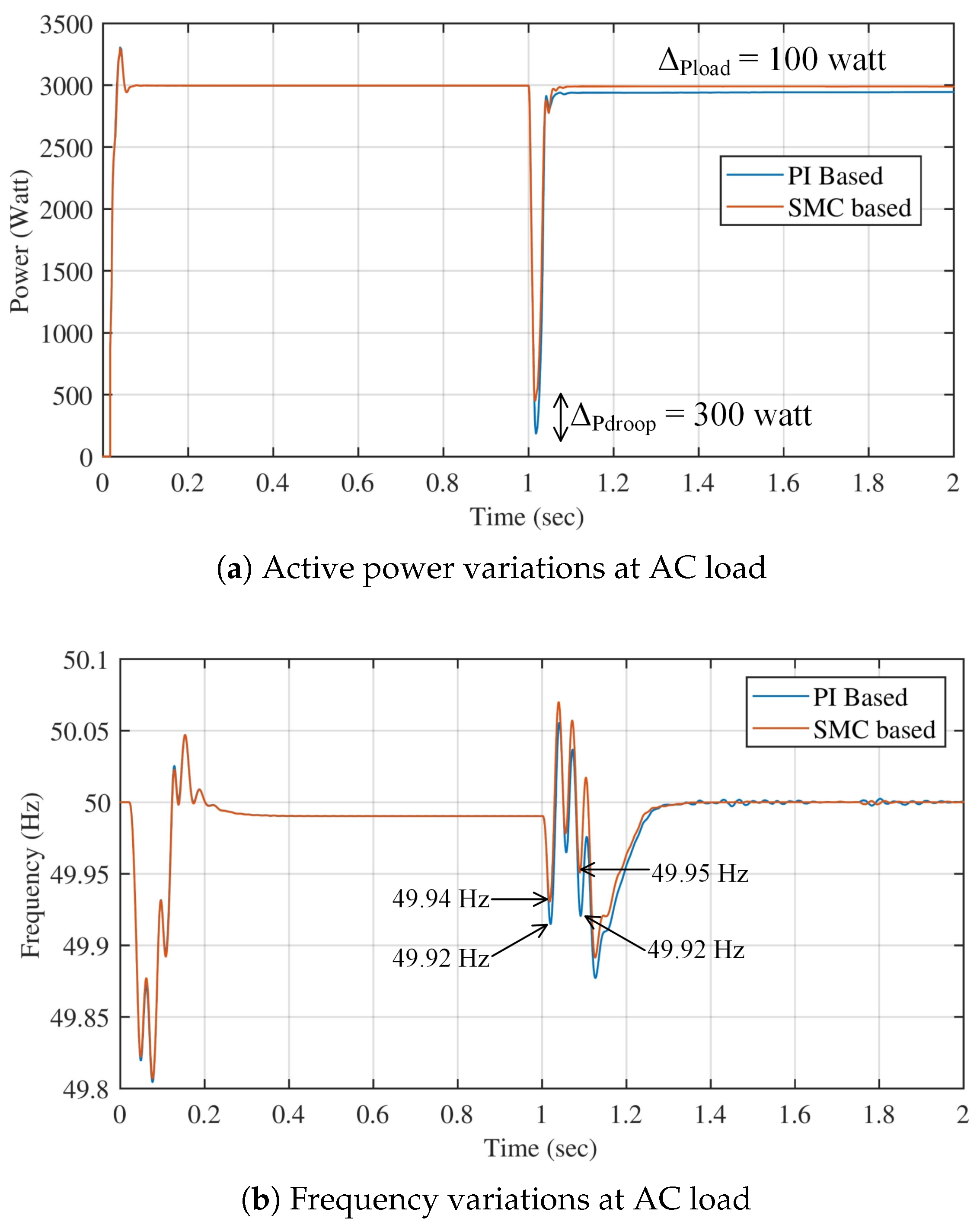
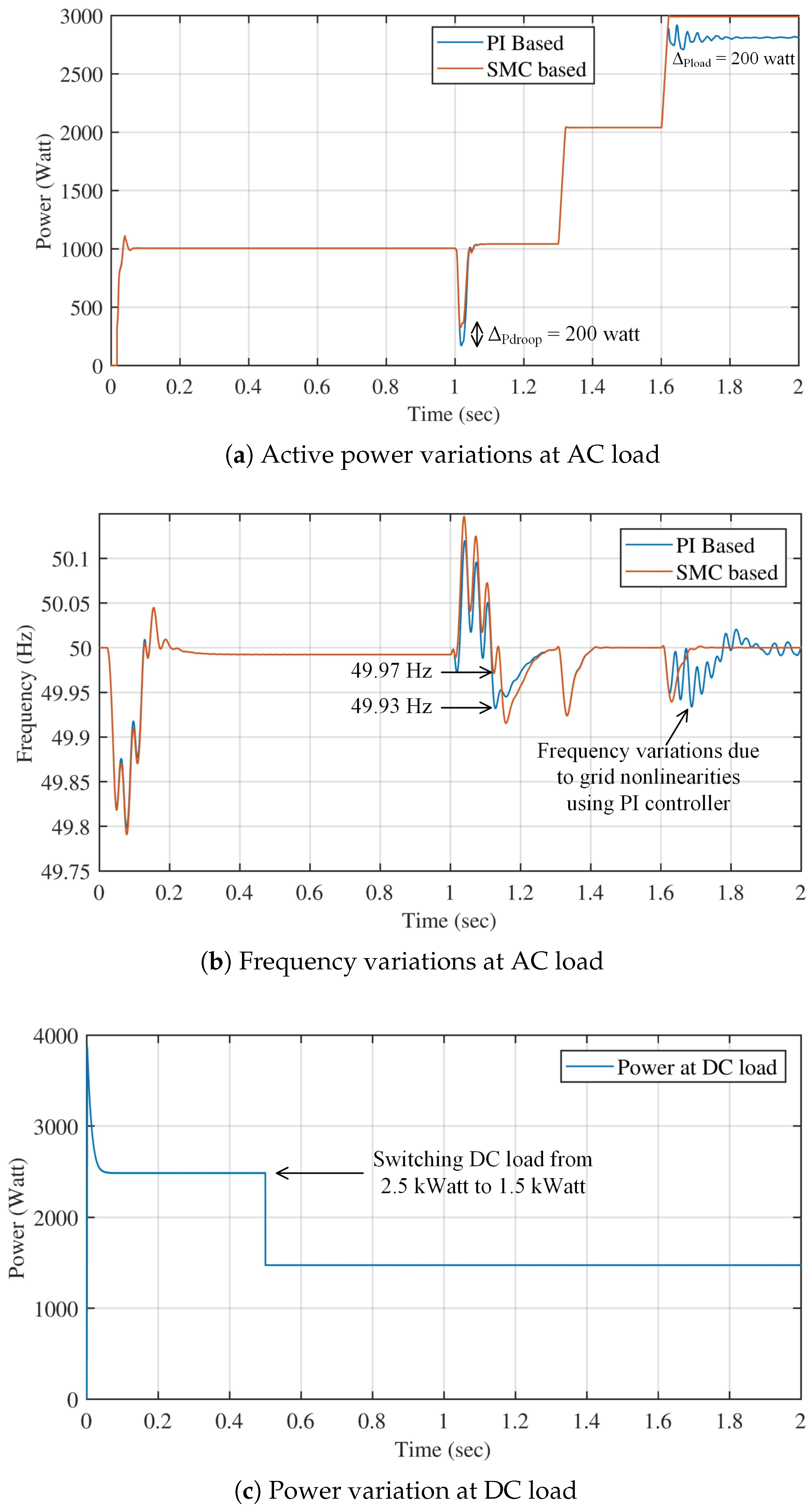
Figure 9a shows the comparison of conventional and proposed secondary controller-based AC load power variations due to microgrid changeover. Initially, the grid is operating from DC source, so AC load power is initially regulated to 3 kW. After time
s, grid changeover occurs, and we can see a power dip due to voltage drop. The power dip was 3 kW by using the conventional secondary controller technique. However, it is improved by a 300 W power dip due to grid changeover. Furthermore, the load power difference between 1 s
s is
W.
Figure 9b compares conventional and proposed secondary controller-based frequency variations due to microgrid changeover. Initially, the grid is operating from DC source, so grid frequency tries to regulate and stabilize at 50 Hz after time
s. After that, grid changeover occurs, and we can see frequency droops in both types of secondary controller cases. However, we can notice a significant improvement in frequency droop steady-state response by employing the proposed secondary controller strategy.
4.3. Case 3: Step Load Increment When Power Flow from AC to DC Side
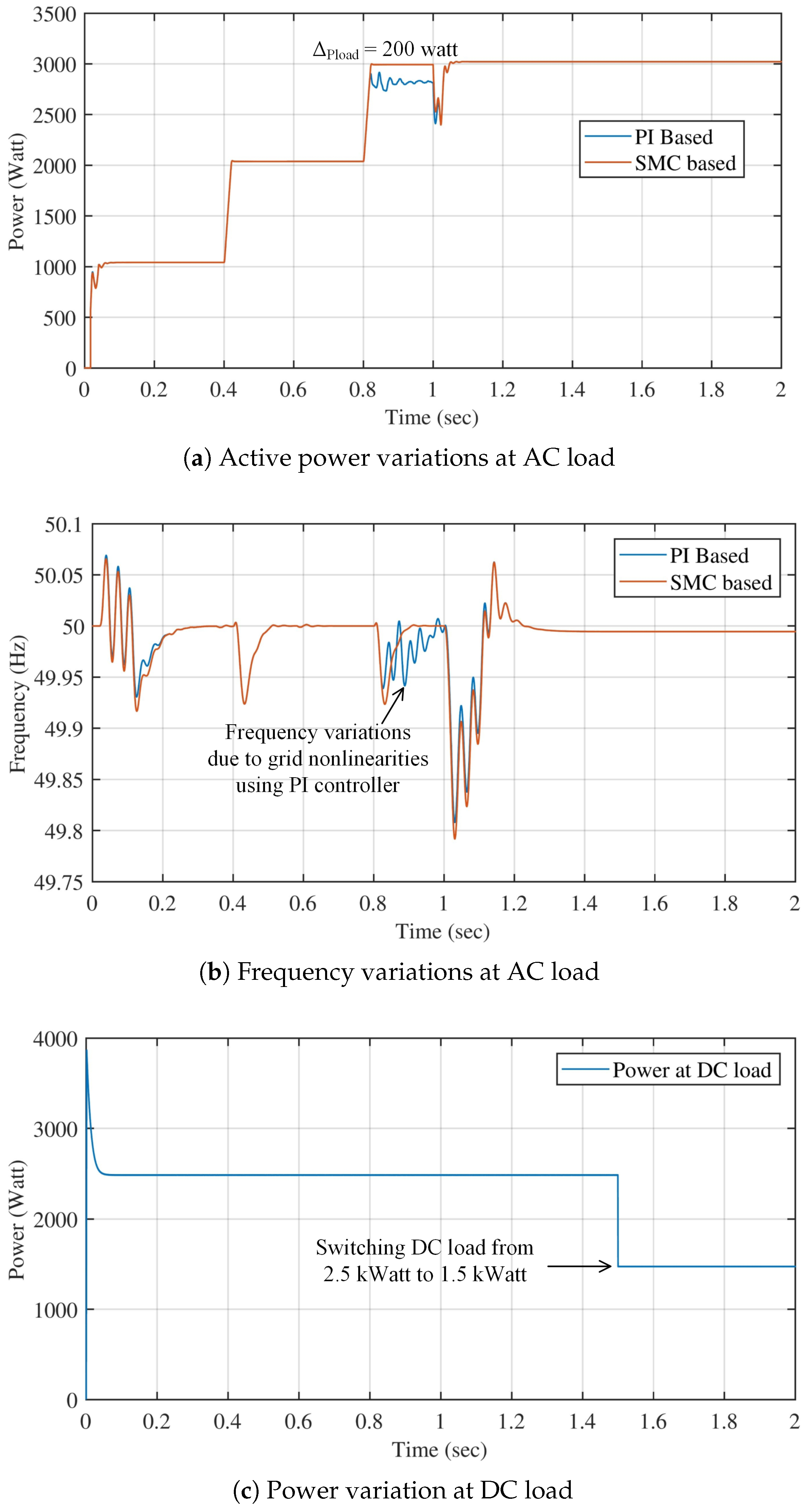
Figure 10a shows the comparison of conventional and proposed secondary controller-based AC load power variations due to microgrid changeover. Initially, the grid is operating from DC source, so AC load power is regulated to 1 kW. After that, grid changeover occurs, and we can see a power dip due to voltage droop. After identical AC load of 1 kW introduced at
s and
s, we found that SMC performed better than PI based hierarchical control under load increments since there is
W at maximum load and
W at grid transition.
Figure 10b compares conventional and proposed secondary controller-based frequency variations due to microgrid changeover. Initially, the grid is operating from DC source, so grid frequency tries to regulate and stabilize at 50 Hz after time
s. After that, grid changeover occurs and step loads are introduced. Here we can realize the robustness of load variations of our proposed design.
4.4. Case 4: Step Load Increment When Power Flow from DC to AC Side
Figure 11a shows comparison of conventional and proposed secondary controller-based AC load power variations due to step load variations on both AC and DC sides. We can observe that AC identical step load increment at
s and
s. We can observe that there is
W at maximum load. Therefore, the performance of the proposed design is better than the PI based designs given in other literature.
Figure 11b shows frequency variation under the influence of step load increments. The behaviour of frequency by using SMC based controller is better than PI based design. Here, we can realize the robustness of load variations of our proposed design as compared to PI-based controller.
Figure 11c shows the DC step load decrement smoothly from
kW to
kW at
s.
4.5. Case 5: Dynamical Load Analysis
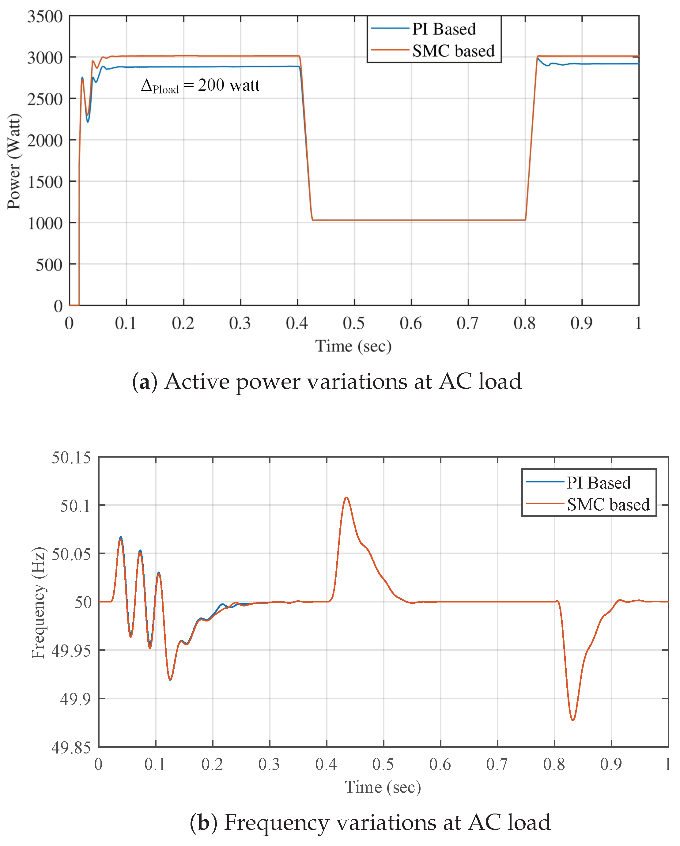
Figure 12a,b above shows the comparison of PI-based control with SMC under step AC load power variations. Initially, from time 0 to
s, 3 kW load is attached to the AC microgrid, and SMC based controller provides an accurate 3 kW to the load. However, the PI-based controller has approximately a 150 W power difference, which can be overcome when AC MG operates at 1 kW or low power loads. This is due to the fact that SMC performs better under dynamic load variations, which has been validated through this case test.
Figure 12a shows that initially, AC MG has 3 kW load which is reduced to 1 kW at
s. Afterward, power is restored to 3 kW at
s. Here, we can observe that there is
W at maximum load, which proves that SMC based controller performed better power regulations.
Figure 12b shows frequency variations on the grid. Frequency seems to have no major effect on using a secondary controller under dynamic load variations.
