

Design of a Smart Barrier to Internal Flooding


Abstract
:1. Introduction
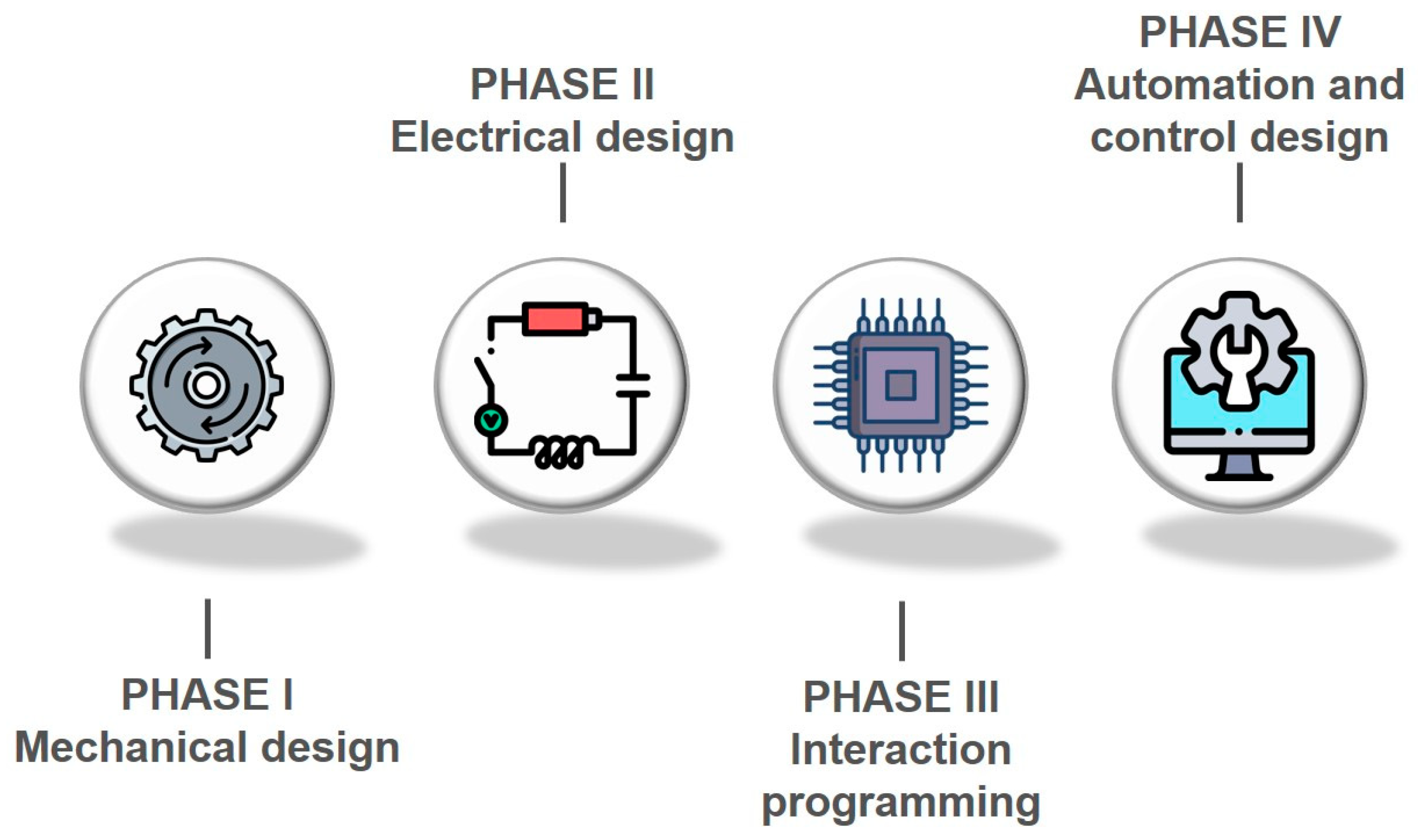
2. Materials and Methods
3. Model Invention
4. Conclusions
5. Patents
Author Contributions
Funding
Institutional Review Board Statement
Informed Consent Statement
Data Availability Statement
Conflicts of Interest
References
- Reiter, K.; Knittel, N.; Bachner, G.; Hochrainer-Stigler, S. Barriers and ways forward to climate risk management against indirect effects of natural disasters: A case study on flood risk in Austria. Clim. Risk Manag. 2022, 36, 100431. [Google Scholar] [CrossRef]
- Yin, Q.; Ntim-Amo, G.; Ran, R.; Xu, D.; Ansah, S.; Hu, J.; Tang, H. Flood Disaster Risk Perception and Urban Households’ Flood Disaster Preparedness: The Case of Accra Metropolis in Ghana. Water 2021, 13, 2328. [Google Scholar] [CrossRef]
- Šakić Trogrlić, R.; Rijke, J.; Dolman, N.; Zevenbergen, C. Rebuild by design in Hoboken: A design competition as a means for achieving flood resilience of urban areas through the implementation of green infrastructure. Water 2018, 10, 553. [Google Scholar] [CrossRef]
- Cavallaro, L.; Iuppa, C.; Foti, E. Effect of partial use of Venice flood barriers. J. Mar. Sci. Eng. 2017, 5, 58. [Google Scholar] [CrossRef]
- Zecchetto, S.; Umgiesser, G.; Brocchini, M. Hindcast of a storm surge induced by local real wind fields in the Venice Lagoon. Cont. Shelf Res. 1997, 17, 1513–1538. [Google Scholar] [CrossRef]
- Obiefuna, J.; Adeaga, O.; Omojola, A.; Atagbaza, A.; Okolie, C. Flood risks to urban development on a coastal barrier landscape of Lekki Peninsula in Lagos, Nigeria. Sci. Afr. 2021, 12, e00787. [Google Scholar] [CrossRef]
- Ventimiglia, U.; Candela, A.; Aronica, G.T. A cost efficiency analysis of flood proofing measures for hydraulic risk mitigation in an urbanized riverine Area. Water 2020, 12, 2395. [Google Scholar] [CrossRef]
- Zang, Y.; Meng, Y.; Guan, X.; Lv, H.; Yan, D. Study on urban flood early warning system considering flood loss. Int. J. Disaster Risk Reduct. 2022, 77, 103042. [Google Scholar] [CrossRef]
- Chen, Y.; Zhou, H.; Zhang, H.; Du, G.; Zhou, J. Urban flood risk warning under rapid urbanization. Environ. Res. 2015, 139, 3–10. [Google Scholar] [CrossRef]
- Wang, S.; Notario, V.; Garlock, M.; Glisic, B. Parameterization of hydrostatic behavior of deployable hypar umbrellas as flood barriers. Thin-Walled Struct. 2021, 163, 107650. [Google Scholar] [CrossRef]
- Martinez, M.; Bakheet, R.; Akib, S. Innovative Techniques in the Context of Actions for Flood Risk Management: A Review. Eng 2021, 2, 1–11. [Google Scholar] [CrossRef]
- Hankin, H.; Page, T.; McShane, G.; Chappell, N.; Spray, C.; Black, A.; Comins, L. How can we plan resilient systems of nature-based mitigation measures in larger catchments for flood risk reduction now and in the future? Water Secur. 2021, 13, 100091. [Google Scholar] [CrossRef]
- Yusoff, S.; Yusoff, N.H. Disaster Risks Management through Adaptive Actions from Human-Based Perspective: Case Study of 2014 Flood Disaster. Sustainability 2022, 14, 7405. [Google Scholar] [CrossRef]
- Ministerio para la Transición Ecológica y el Reto Demográfico. Available online: https://www.miteco.gob.es/es/agua/temas/gestion-de-los-riesgos-de-inundacion/ (accessed on 2 August 2022).
- Munyai, R.B.; Chikoore, H.; Musyoki, A.; Chakwizira, J.; Muofhe, T.P.; Xulu, N.G.; Manyanya, T.C. Vulnerability and Adaptation to Flood Hazards in Rural Settlements of Limpopo Province, South Africa. Water 2021, 13, 3490. [Google Scholar] [CrossRef]
- Nofal, O.M.; van de Lindt, J.W.; Cutler, H.; Shields, M.; Crofton, K. Modeling the Impact of Building-Level Flood Mitigation Measures Made Possible by Early Flood Warnings on Community-Level Flood Loss Reduction. Buildings 2021, 11, 475. [Google Scholar] [CrossRef]
- Anti-Flood-barriers. Available online: https://www.anti-flood-barriers.com/ (accessed on 3 August 2022).
- Flood Ark. Available online: https://www.floodark.com/ (accessed on 7 August 2022).
- Lakeside Flood Solutions. Available online: https://www.lakesidefloodsolutions.co.uk/ (accessed on 3 August 2022).
- LCF Technologies. Available online: https://www.lcftech.es/ (accessed on 7 August 2022).
- Flood Control International. Available online: https://floodcontrolinternational.com/ (accessed on 3 August 2022).
- Código Técnico de la Edificación (CTE). Available online: https://www.codigotecnico.org/ (accessed on 11 July 2022).
- Documento Básico de Seguridad de Utilización y Accesibilidad. Available online: https://www.codigotecnico.org/DocumentosCTE/SeguridadUtilizacionAccesibilidad.html (accessed on 11 July 2022).
- Normativa Para de Comercialización y Puesta en Servicio de las Máquinas R.D. 1644/2008. Available online: https://www.boe.es/buscar/act.php?id=BOE-A-2008-16387 (accessed on 23 August 2022).
- Normativa Europea de Seguridad Para Puertas Automáticas y Automatismos (UNE-EN 13241-1). Available online: https://www.une.org/encuentra-tu-norma/busca-tu-norma/norma/?c=N0058254 (accessed on 23 August 2022).
- Directiva de Compatibilidad Electromagnética (2004/108/CE). Afecta a los dispositivos eléctricos y electrónicos capaces de generar perturbaciones electromagnéticas o que pueden verse afectados por estas (cuadros, dispositivos de mando o de seguridad, etc.). Real Decreto 1580/2006, de 22 de diciembre, por el que se regula la compatibilidad electromagnética de los equipos eléctricos y electrónicos (boe.es). Available online: https://www.boe.es/buscar/doc.php?id=DOUE-L-2014-80623 (accessed on 22 August 2022).
- Reglamento Electrotécnico de baja Tensión R.D.842/2002, R.D. 560/2010 y R.D. 244/2019. Available online: https://www.boe.es/diario_boe/txt.php?id=BOE-A-2002-18099 (accessed on 23 August 2022).
- Samansiri, S.; Fernando, T.; Ingirige, B. Advanced technologies for offering situational intelligence in flood warning and response systems: A literature review. Water 2022, 14, 2091. [Google Scholar] [CrossRef]
- Mutchek, M.; Williams, E. Moving towards sustainable and resilient smart water grids. Challenges 2014, 5, 123–137. [Google Scholar] [CrossRef]
- Liu, Z.; Huang, J.; Wang, Q.; Wang, Y.; Fu, J. Real-time barrier lakes monitoring and warning system based on wireless sensor network. In Proceedings of the 2013 Fourth International Conference on Intelligent Control and Information Processing, Beijing, China, 9–11 June 2013; pp. 551–554. [Google Scholar] [CrossRef]


| Patent | SFB Comparative Advantage |
|---|---|
| Anti-Flood Barriers [17] | The flood forecast must be known in order to pre-assemble the barrier. However, SFB is a stand-alone system and can be controlled remotely. |
| Floodark [18] | This is a manually assembled barrier, requiring installation prior to flooding. It is based on a modular system in which a certain number of modules can be selected to cover the desired height. The joints present watertightness problems. SFB is a complete barrier, without intermediate joints, and can be manufactured to the height needed by the client. |
| Lakeside Flood Solutions [19] | Similar to the SFB system, except that in this case, the barrier is raised mechanically by flooding the moat, with the barrier having a flotation system at the bottom. This system has the disadvantage of not filling the moat properly if the inlet nozzle is blocked by mud or objects dragged by the flood. |
| LCF Technologies [20] | Containment system by manual installation, with an automatic system for shop doors that are installed on the closing shutter. This system is not viable in this case as many shops do not require locking systems and their entrances and shop windows are visible to the public. In addition, they have a rubber-butyl system that is similar to SFB to hermetically seals the perimeter, but which can be degraded by friction as the barrier moves. In SFB, the chamber rises deflated and inflates once the barrier is fully deployed. |
| Flood Control International [21] | This system has numerous types and models for different applications. In the case of its automatic barrier, it is presented as a folding barrier, installed on the ground, of great height and weight, mainly indicated for garage doors, preventing them from being flooded by the water of a flood. Its lifting system is formed by a hydraulic cylinder and chains that, when activated by sensors or remotely, close the door preventing the entry of water. As SFB is smaller in size, its application is focused on entrance doors of single-family dwellings, or doors of communal dwellings. Furthermore, with regard to electricity consumption, this is lower due to the lower weight of our system. Finally, SFB is more environmentally friendly as leakage of hydraulic oil can cause accidents and environmental pollution. |
| Identification Number | Component | Description |
|---|---|---|
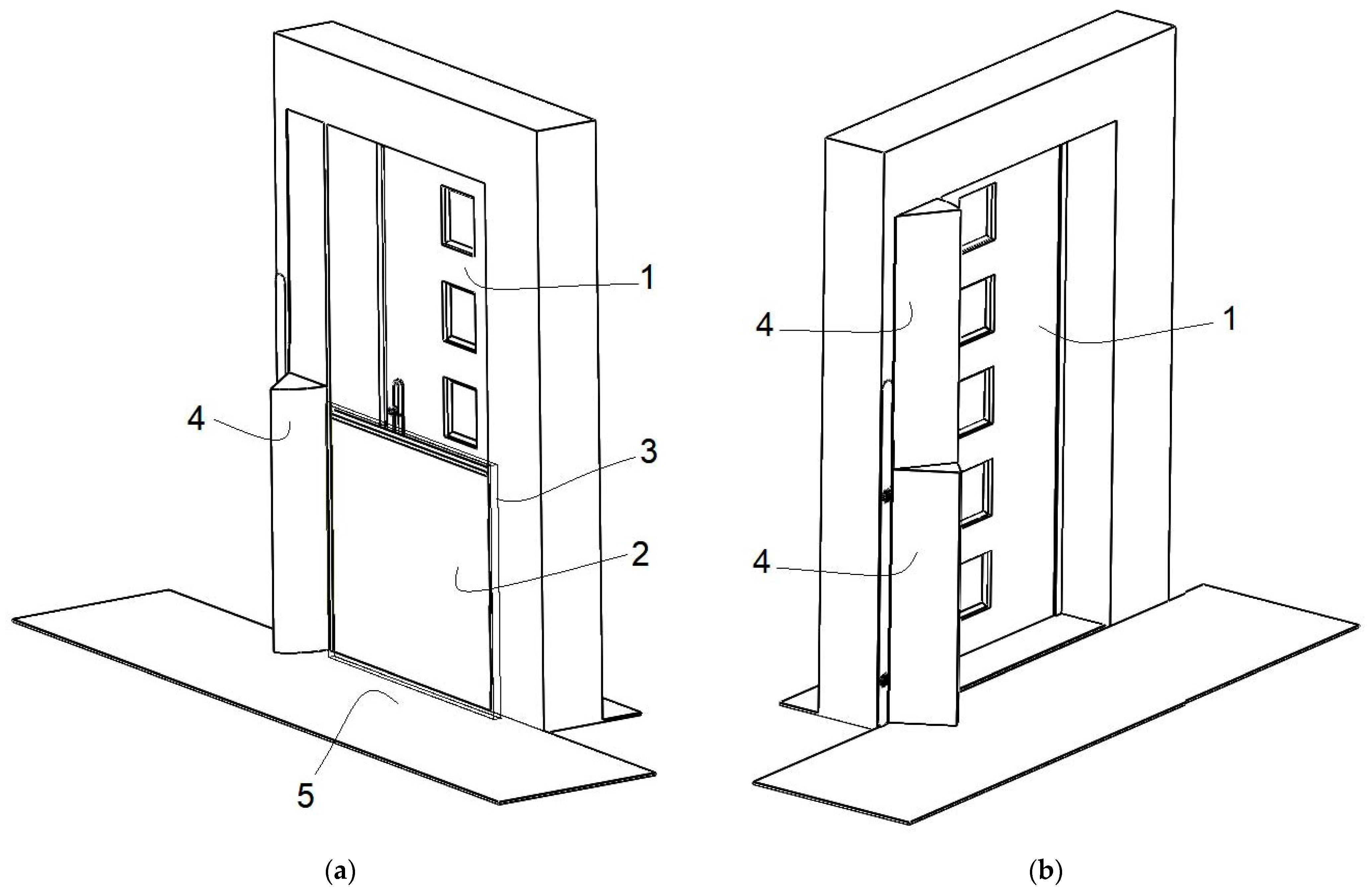
| 1 | Door | It is not directly part of the invention, but is fundamental to prevent water from entering the home. |
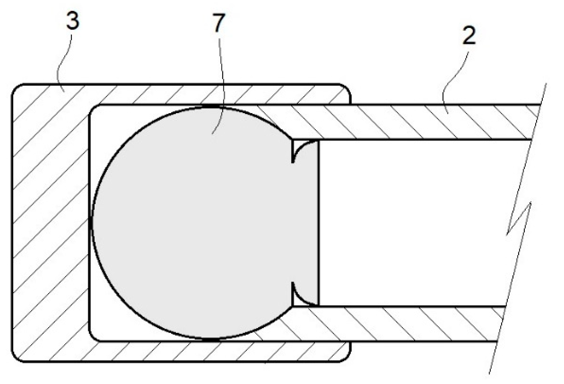
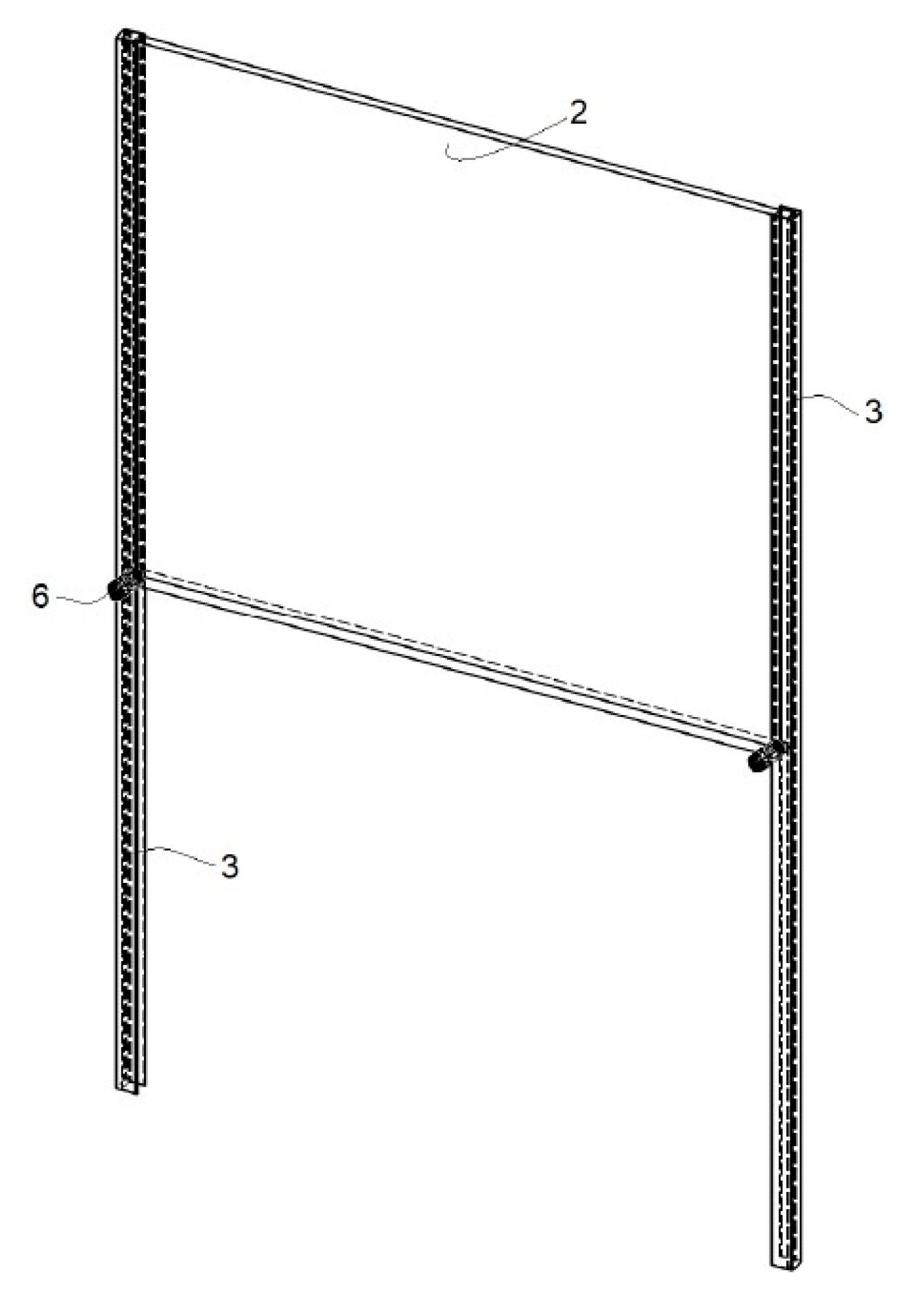
| 2 | Barrier | Hidden below the ground and which is automatically raised when there is a certain level of water. |
| 3 | Lateral Guides | Fixed to the pillars of the gate to be protected and has a peripheral chamber |
| 4 | Lintel | Installed on the right or left side of the gate depending on the slope of the street or sidewalk |
| 5 | Access | To be protected and which once fully raised closes in a watertight manner totally preventing the passage of water up to the gate |
| 6 | Valves | Connects to a small pneumatic compressor |
| 7 | Chamber | Installed perimetrically to ensure the sealing. |
| Identification Number | Component | Cost (USD) |
| 2 | Barrier | 1200 |
| 3 | Lateral Guides | 500 |
| 4 | Lintel | 2000 |
| 5 | Access | 500 |
| 6 | Valves | 250 |
| 7 | Chamber | 100 |
| - | Other components | 1500 |
| - | Variable costs | 1000 |
| - | Assembly cost | 1850 |
| - | Total implementation cost | 8000 |
Publisher’s Note: MDPI stays neutral with regard to jurisdictional claims in published maps and institutional affiliations. |
© 2022 by the authors. Licensee MDPI, Basel, Switzerland. This article is an open access article distributed under the terms and conditions of the Creative Commons Attribution (CC BY) license (https://creativecommons.org/licenses/by/4.0/).
Share and Cite
Muñoz-Caballero, J.; Vergara, D.; Fernández-Arias, P.; Antón-Sancho, Á. Design of a Smart Barrier to Internal Flooding. Inventions 2022, 7, 88. https://doi.org/10.3390/inventions7040088
Muñoz-Caballero J, Vergara D, Fernández-Arias P, Antón-Sancho Á. Design of a Smart Barrier to Internal Flooding. Inventions. 2022; 7(4):88. https://doi.org/10.3390/inventions7040088
Chicago/Turabian StyleMuñoz-Caballero, Jorge, Diego Vergara, Pablo Fernández-Arias, and Álvaro Antón-Sancho. 2022. "Design of a Smart Barrier to Internal Flooding" Inventions 7, no. 4: 88. https://doi.org/10.3390/inventions7040088
APA StyleMuñoz-Caballero, J., Vergara, D., Fernández-Arias, P., & Antón-Sancho, Á. (2022). Design of a Smart Barrier to Internal Flooding. Inventions, 7(4), 88. https://doi.org/10.3390/inventions7040088