Article

Development of a Mathematical Model for Solid Fuel Gasification and Its Sensitivity Analysis

1
Department of Innovative Technologies of High-Tech Industries, National Research University “Moscow Power Engineering Institute”, 111250 Moscow, Russia
2
Department of Thermal Power Plants, National Research University “Moscow Power Engineering Institute”, 111250 Moscow, Russia
*
Author to whom correspondence should be addressed.
Inventions 2022, 7(3), 65; https://doi.org/10.3390/inventions7030065
Submission received: 30 May 2022 / Revised: 7 July 2022 / Accepted: 25 July 2022 / Published: 29 July 2022

Abstract

:
Within the framework of this study, a brief review of the gasification technology was carried out, the best types of blowing agents and gasification methods used in terms of efficiency and environmental safety were identified, and a mathematical model of a steam–oxygen gasifier was developed in the MS Excel software package. The authors paid special attention to the consideration of the effect of changing the input parameters of the syngas, such as the temperature and relative mass flow rate of steam and oxygen, on the heat of the combustion of the produced syngas. As a result of the research, methods for increasing the heat of the combustion of the syngas and the conditions for using the described methods were formulated. The work also revealed the optimal ratios of the blowing agents and solid fuel supplied for gasification and presented the output parameters of the produced generator gas, including the heat of combustion of the gas, the gas temperature, and the gasification efficiency. Computer simulation models of the gasifier and gasification process were the basis for the analysis of a combined cycle (CC) facility with an integrated solid fuel gasifier. The heat flow thermodynamic analysis shows that the gasification steam bleeding from the turbine is the best solution for the improvement of cycle efficiency.

1. Introduction

1.1. Study Topicality

In spite of the worldwide rapid introduction of renewable power sources, a major portion of thermal and electrical energy is generated from burning organic fuels by converting their chemical energy at the thermal power plant. In the foreseeable future, fossil fuels will continue to be crucial for electricity generation [1]. Products of combustion of organic fossil fuels are emitted as solid aerosols, sulfur oxides, nitrogen oxides, and the bulk as carbon dioxide. This acts as a major contributor to the greenhouse effect, which leads to global warming [2].
Due to the dwindling oil and gas resources and the growing demands for environmental protection, the conversion of coal into a gaseous energy carrier is of great importance. Subsequently, the solid fuel gasification process can be used as a source of gas fuel in cycles which capture carbon dioxide and, thereby, enable the use of sustainable and low-toxic material cycles, which has become one of the most promising areas in the energy industry [3,4]. For both the economy and the environment, the rapid increase in research activity and the application of new breakthroughs in this industry are top priorities [5].
According to the research in [6], fuel gas is the most popular raw material used to generate thermal and electrical energy because it is environmentally friendly, easy to transport, and widespread. The processing of coal to produce a gaseous source of energy becomes critical in light of tougher environmental requirements due to rising prices for carbon emissions trading quotas [7]. In addition, coal gasification makes it possible to shift combined cycle gas turbines (CCGTs) to coal fuels, which presents the problem of comparing the energy efficiency of CCGTs and coal-fired steam turbine units with ultra-supercritical steam parameters [8].
Gasification is a promising solid fuel conversion technology in which the initial feedstock is partially oxidized, either by air or by oxygen and steam, to generate producer gas (syngas). The main ingredients of syngas are carbon monoxide and hydrogen [9]. The generated syngas can be used to produce thermal or electrical energy or to produce both at the same time by cogeneration [10]. Before being fed into the gas turbine unit, the syngas is cleaned from dust and ash in a filter, and then the exhaust gases are sent to a waste heat boiler, which generates superheated steam [11].
The prospects for integrating the gasification process in CCGT pose the task of studying the effect of the gasification process on the efficiency of the cycle. First of all, a mathematical model is needed that can predict the change in the composition and heat of combustion of the generator gas in a wide range of changes regarding the type and thermodynamic parameters of the blast. At the same time, it is necessary to evaluate the energy efficiency of the CCGT cycle with coal gasification, depending on the sampling points and the parameters of the blast supplied to the gasifier. The cumulative results of the calculations will make it possible to determine the optimal operating parameters of the gasifier from the point of view of cycle efficiency.

1.2. Solid Fuel Gasification

The rate of gasification processes, calorific value, thermodynamic parameters, and composition of syngas depend upon the following factors [7,12,13]: type and proportion of the used gasifying agents, composition of solid fuels, gasification pressure, and the temperatures of oxygen and steam. Depending on the type of gasification environment and gasification products, there may be various chemical interactions occurring between the components. Gasifiers with steam and oxygen proved to be the best gasification facilities in terms of environmental indicators and performance [14].
Entrained-flow gasification and fluidized-bed gasification are currently seen as the most promising methods [15]. The use of entrained-flow gasifiers makes it possible to increase the calorific value of the gas; however, the lifespan of the gasifier burners and units is shorter because of high temperatures of the syngas. With entrained-flow gasification, it is undesirable to use coals with a high ash content and high ash fusion temperatures [16].
The gasification agent contents and thermodynamic parameters mainly determine the gasification process and the final contents of gas fuel (ref. Table 1).
The gasification reactions with technically acceptable velocities require the high temperatures that practically exclude the formation of high hydrocarbons. The blow type and the solid fuel contents influence the gasification process velocity, the syngas LHV, and the thermodynamic parameters. Moreover, these also influence the gasifier inlet pressure, gasification agent contents, and the supplied oxygen, air, and steam ratios [12,17]. The research in [18] shows that an increase in the temperature of the solid fuel reaction using oxidizers reduces the CO2 content in the produced syngas.
Available papers describe many gasification processes. The Winkler method of gasification involves a gasifier with a fluidized bed (CFB) layer of 0.8–10 mm size solid fuel particles, with 5–10% humidity and dry ash evacuation. The gasifier type is a straight flow pit reactor with 0.10–1.5 MPa pressure and 850–1100 °C maximal temperature. Its syngas is rich in hydrogen and carbon monoxide and has the combustible products volume up to 85%. The blow agents are steam–oxygen or steam–air mixtures [18]. The Lurgi process is steam–oxygen gasification in a layer on the rotating grid. It has a combustibles volume production up to 70% and a high methane contents due to the gasifier pressure of 3 MPa [18]. The study in [19] shows the high power and environmental efficiencies of the steam–oxygen blow gasifier that operates Shell technology by Siemens. In this process, the blow gas oxygen content is 80–90%, and the syngas has a 85–90% combustible components content.
Despite the fact that the literature contains a large amount of data on gasification technologies, it does not allow for a qualitative assessment of changes in the composition, temperature, and heat of combustion of synthesis gas when one or more process parameters (temperature, composition, blast mass flow) are varied.

1.3. Combined Cycles with Inter-Cycle Gasification

Gasifier integration into the CC facility flow scheme is a prospective direction of solid fuel gasification. This is due to the availability of all agents needed for efficient solid fuel gasification, namely air, oxygen, and steam. A compressor air bleeding may supply air to a gasifier, or to an air split facility, for pure oxygen production. The gasification steam may be taken from the heat recovery boiler, or from the steam turbine flow path. Use of the turbine steam reduces the condenser heat losses, which improves the CC facility efficiency.
The research in [19] describes a CC facility with a steam–oxygen blow gasifier and the compressor air bleeding into an air split unit (ASU). The steam supplied from the heat recovery boiler into the gasifier increases the syngas LHV. The compressed air supply to ASF from the GT compressor reduces the additional equipment investments, as the compressor upstream ASU is not needed. This scheme has a few shortcomings. The facility startup requires a reserve fuel. Air pressure drop at transient operating regimes will influence the gasification process, which will cause changes in the contents of the produced syngas. The study in [20] describes a CC facility with a steam–oxygen blow and CO2 capture upstream of the syngas combustion. Unfortunately, the paper does not show the source of the high pressure (2.7 MPa) steam supplied to the gasifier. The research in [21] evaluates the efficiency of a CC facility with inter-cycle gasification and CO2 capture before combustion. The authors of this paper estimate that 8–12% of the power production is spent for the carbon dioxide capture; thus, the CO2 capture remarkably reduces the cycle efficiency. The authors of [22] describe a CC facility with coal gasification and high blown air prior to heating. The paper’s authors assume that the supply of hotter air increases the syngas LHV, but the cycle efficiency is not shown. Paper [23] describes an efficiency improvement method for a CC facility using the M701F4 gas turbine. The method includes the pre-heating of the air using an external source prior to the gasifier and GT combustor. The proposed solutions allow for the increase in the cycle net efficiency of up to 50.64%.
The studies in [23,24] describe the Buggenum (Netherland) power plant, equipped with a CC facility with inter-cycle gasification. The facility power is 353 MW, and its net efficiency 43.2%. It is worth mentioning that the existing CC plants with steam–oxygen coal gasification have efficiencies below 45%.
The authors of this work estimate that in the available sources, there are no data on the evaluation of the syngas contents and LHV for the CC regarding gasification thermodynamic analysis, syngas contents determination, blow temperature, and bleeding source choice.
Thus, the study goals are the following:
  • The development of a computer simulation model of a steam–oxygen gasifier with provisions for analysis of the syngas contents and LHV related to the blowing agent contents and thermodynamic parameters;
  • The development of flow schemes for the CC with coal gasification that provide minimal harmful emissions using oxygen combustion and CO2 capture;
  • The evaluation of the integrated solid fuel gasification on the cycle power production efficiency.

2. Research Object and Methods

2.1. Research Object

Mathematical modeling, which is used as a research method, makes it possible to predict the composition and properties of the produced syngas; therefore, thermodynamic and chemical processes should be competently considered in the developed models [25], based on the method proposed by S.K. Popov to model a solid fuel gasification process [26].
The mathematical model of solid fuel gasification is based on a thermodynamic equilibrium approach that is determined by the equilibrium of the chemical reactions of the water–gas shift reaction and the steam reforming of methane (1,2):
H 2 O + CO CO 2 + H 2 ,
CH 4 + H 2 O CO + 3 H 2
The modeling of thermal performance of the gasifier was based on the following conditions and assumptions:
(1) The gasifier is operated continuously and is in the steady thermal state;
(2) Constant pressure is maintained in the gasifier;
(3) Oxygen-enriched air and water steam act as an oxidizer;
(4) Hydrogen, nitrogen, and oxygen are fully involved in the syngas generation; that is, their entire masses react in the process of the gasification reaction;
(5) Ash and syngas leave the gasifier as a single stream, having the same temperature;
(6) Syngas consists of carbon dioxide, carbon monoxide, water, hydrogen, nitrogen, and methane (the syngas components are in a state of thermodynamic equilibrium when they leave the gasifier).
The modeling algorithm is as follows.
(1) Set initial data to be used for calculations, i.e., as-received fuel percentage composition and the parameters of the oxidizer components—temperatures and relative mass flow rates of oxygen and steam, physical properties of fuel moisture, heat, and percentage of external heat losses.
(2) Define auxiliary functions, i.e., temperature functions for specific heat; temperature dependences between equilibrium constants of reactions of dissociation into atoms of H2O, CO, CO2, and H2 molecules (necessary to find the equilibrium constant of the reaction of water–gas) for the water–gas reactions and for the steam–methane reforming reactions; temperature functions for the specific heat of combustible gases, the specific heat of the oxidizer, and the specific heat of the syngas.
(3) Calculate specific volumes of chemical elements in fuel, theoretical flow rate of oxygen from a mixture of nitrogen and oxygen, oxidizer flow rate coefficient—ratio of oxygen mass flow to purity, actual oxidizer flow rate, and specific volumes of chemical elements in the oxidizer, according to the expressions [17,19]:
v C O + v C O 2 + v C H 4 = v C
2 · v H 2 + 2 · v H 2 O + 4 · v C H 4 = v H
2 · v H 2 + 2 · v H 2 O + 4 · v C H 4 = v H ,
v C O + v C O 2 + v H 2 O = v O
2 · v N 2 = v N ,
Specific volumes of chemical elements are measured using the formula below (8).
v = 0.01 · V m M el · n · V el ,
where Vm stands for molar volume of gases under normal conditions, l; Mel stands for molar mass of a chemical element, g/mol; n stands for the number of atoms of a chemical element in the feedstock; Vel stands for content of a chemical element in the feedstock by volume, %.
(4) Solve the equation system that links specific volumes of the source chemical elements and specific yield of the resulting syngas.
(5) Perform thermal design of the reactor (9) and specify the syngas temperature.
Q f cv + Q f sens + Q ox = Q sg cv + Q sg sens + Q evp + Q env + Q ash ,
where Q f cv stands for calorific value of the fuel, kJ/(kg of fuel); Q f sens stands for sensible heat of the fuel, kJ/(kg of fuel); Qox stands for sensible heat of the oxidizer, kJ/(kg of fuel); Q sg cv stands for calorific value of the syngas, kJ/(kg of fuel); Q sg sens stands for sensible heat of the syngas, kJ/(kg of fuel); Qevp stands for heat consumed for evaporation of moisture contained in the fuel, kJ/(kg of fuel); Qenv stands for external heat losses through the gasifier wall, kJ/(kg of fuel); and Qash stands for sensible heat of ash, kJ/(kg of fuel).
(6) After all necessary values are determined, the initial values of the syngas temperature and its components production are assumed. The solving equations system includes the chemical elements mass balance equations and the active masses law equations for the humid gas reaction (5) and steam conversion (6).
v s . g C O 2 · v s . g H 2 v s . g H 2 O · v s . g C O = K p 1 ( t s . g ) ,
v s . g C O · ( v s . g H 2 ) 3 v s . g H 2 O · v s . g C H 4 · P g v s . g = K p 2 ( t s . g ) ,
where Pg—gasifier pressure, bar; Kp1, Kp2—equilibrium constants for the reactions of water–gas and methane steam conversion that are found from the atomization coefficients.
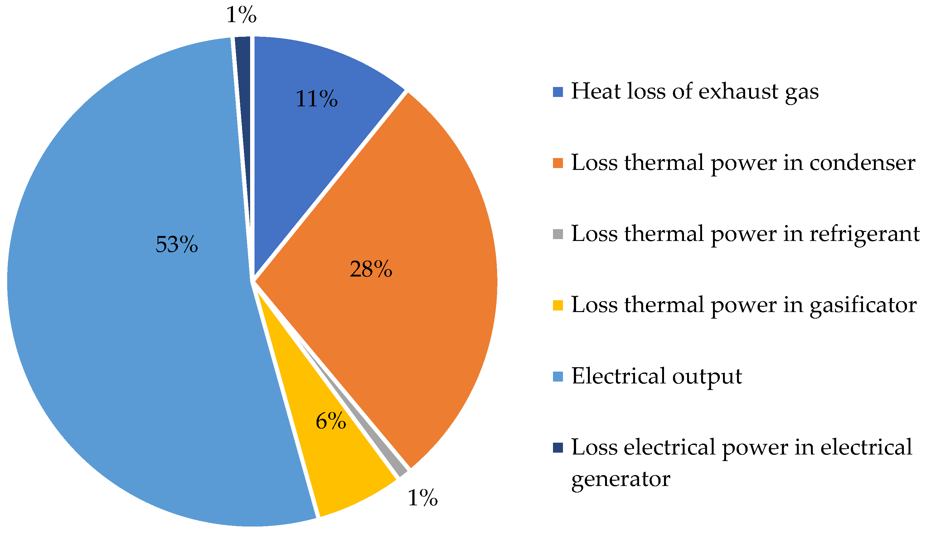
(7) The final results of the calculations are as follows: specific yield of the syngas components, percentage composition of the syngas, temperature of the syngas, specific yield of hydrogen, hydrogen production efficiency, calorific value of the syngas, the structure of the heat balance (the distribution of the heat energy supplied to a thermomechanical system among the various drains upon it, including both useful output and losses) of the gasification reactor, chemical efficiency of gasification (7), and the thermal efficiency of gasification (8).
η chem = Q pg chem Q T chem ,
η therm = Q pg chem + Q pg phys Q T chem + Q T phys + Q ox .
The developed model helps calculate specific volumes of the chemical elements within the syngas, its temperature, and calorific value. Coal properties (Table 2) and operation parameters of the gasifier (Table 3) are set as initial data [2].
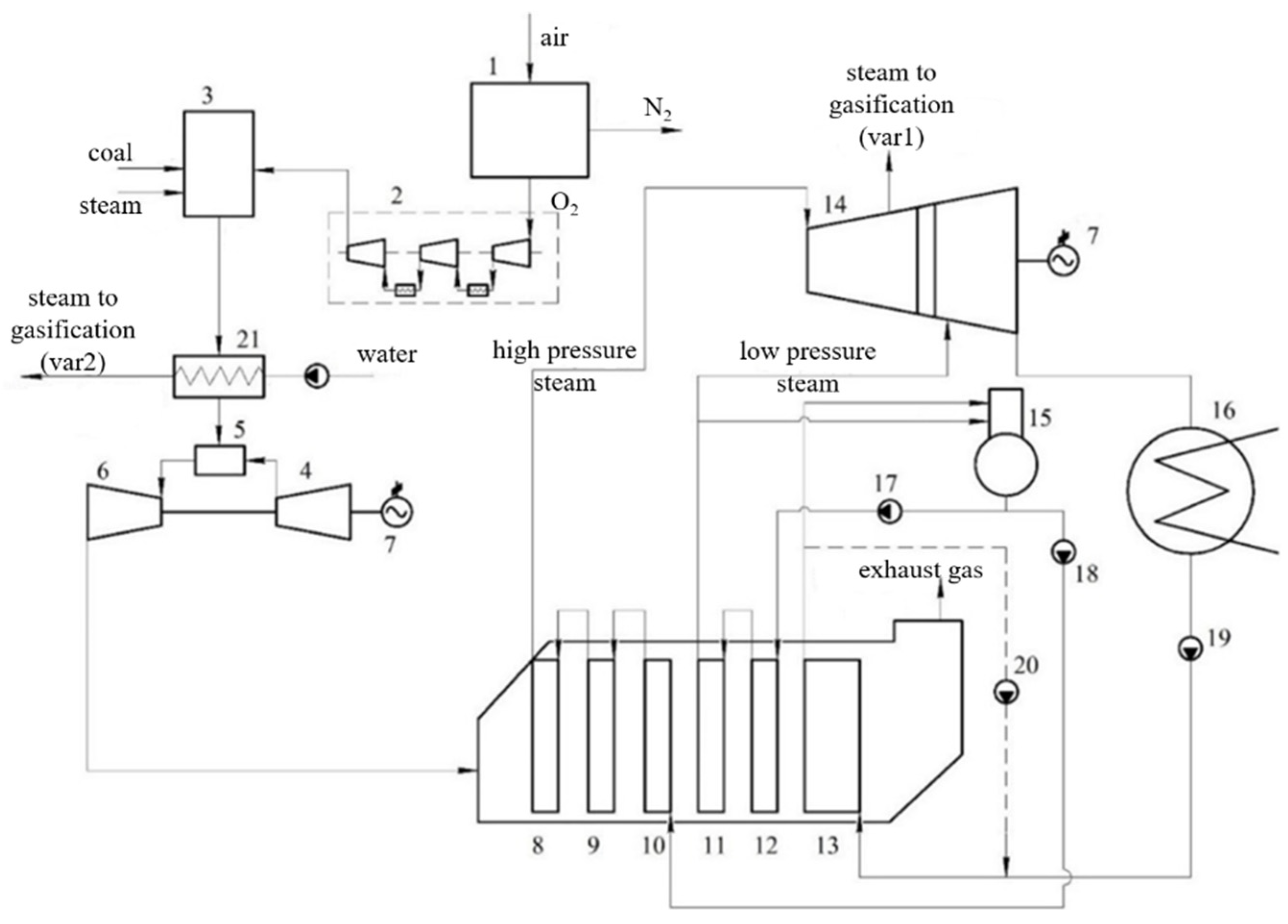
Figure 1 shows a heat flow scheme of the investigated CC with fuel gasification.
The thermal efficiency evaluation algorithm is a combination of widely known CC heat flow analysis methods, including the model built using Aspen Plus computer code. The only exclusion is the analysis of syngas parameters at the gasifier exit, which follows the above-described method. The heat flow analysis input data are summarized in Table 4.

2.2. Methods

To understand the correct functioning of the developed model, the calculation results were verified with the results of the research in [27]. The results are presented in Table 5.
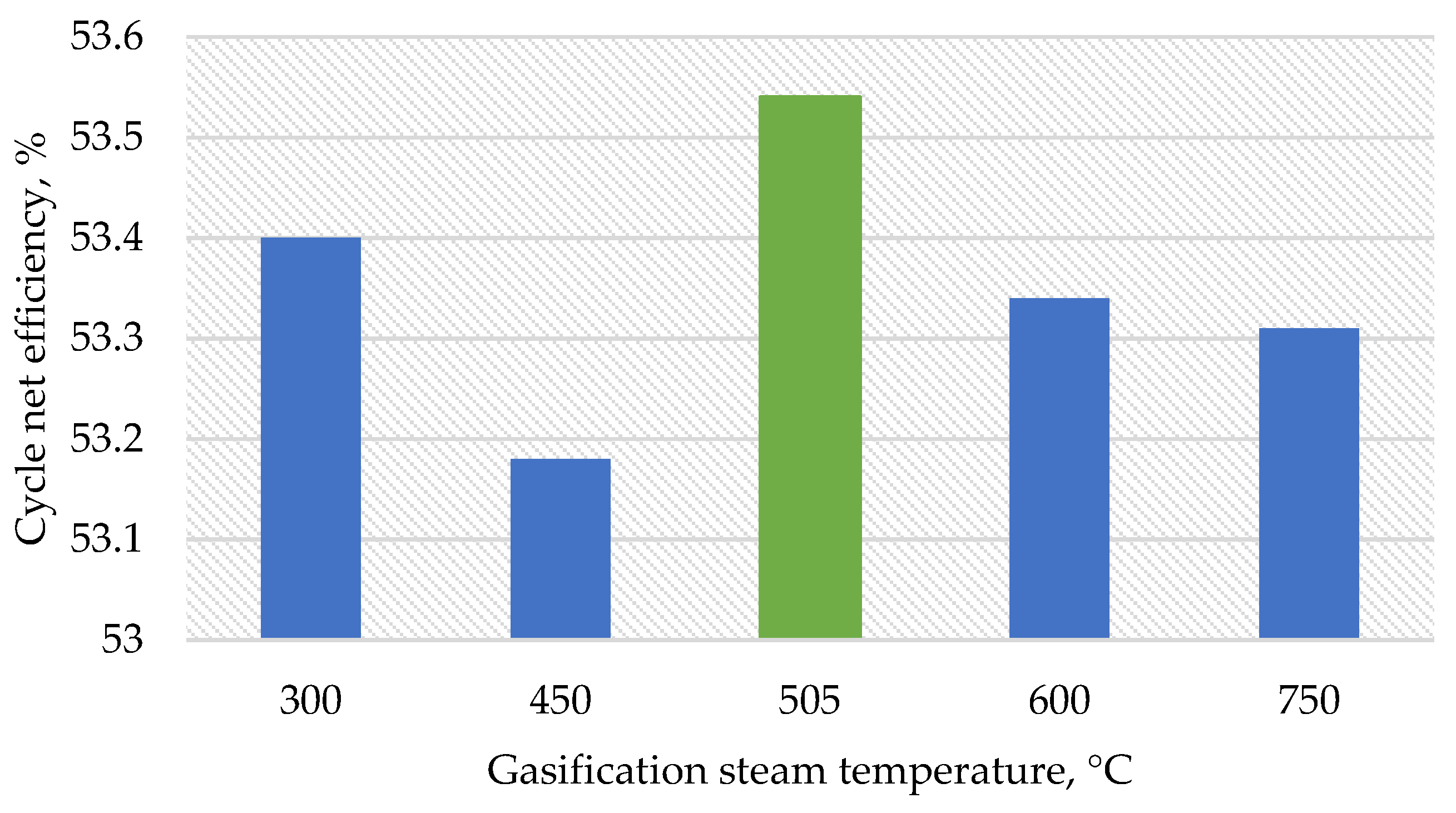
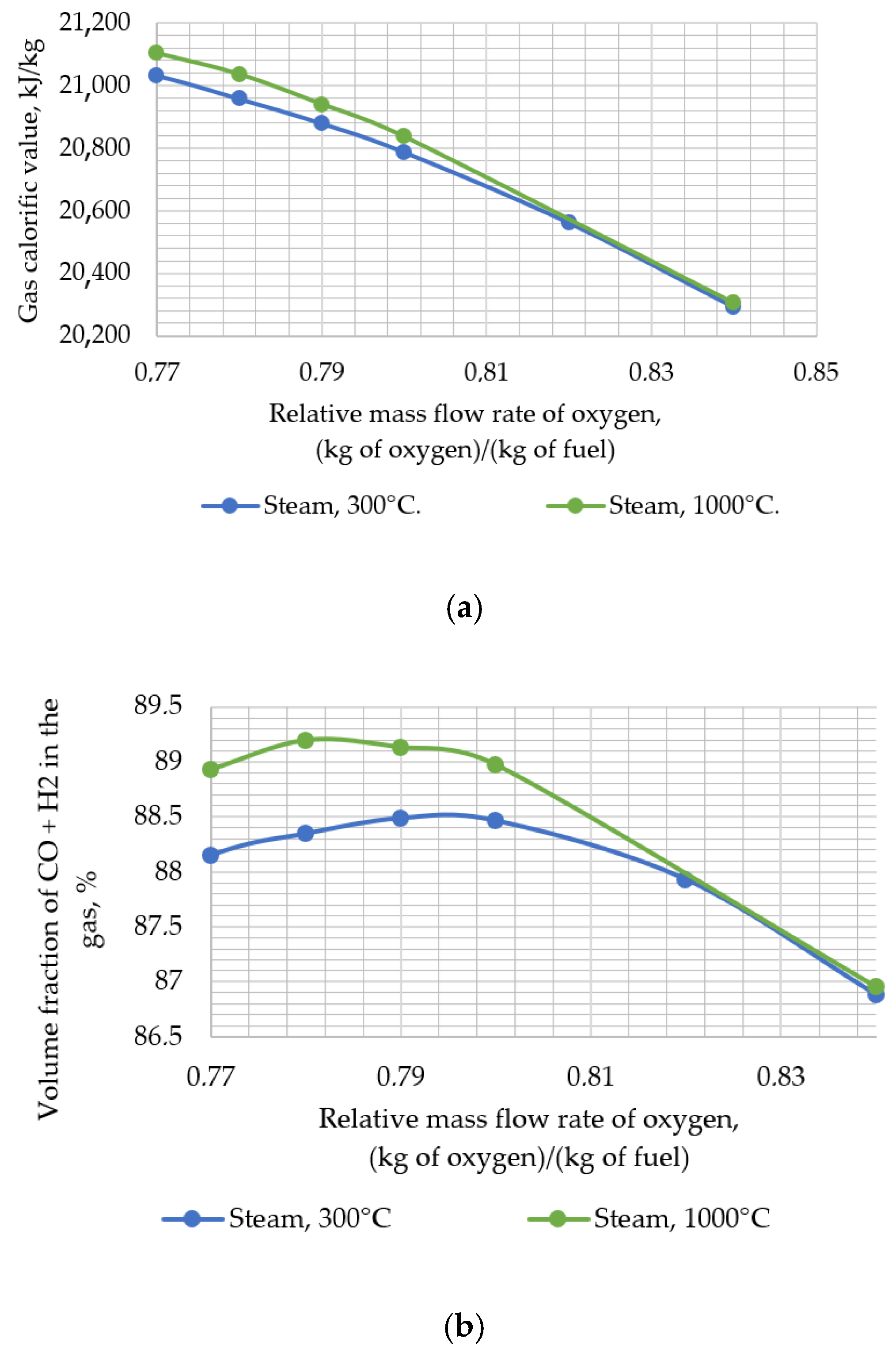
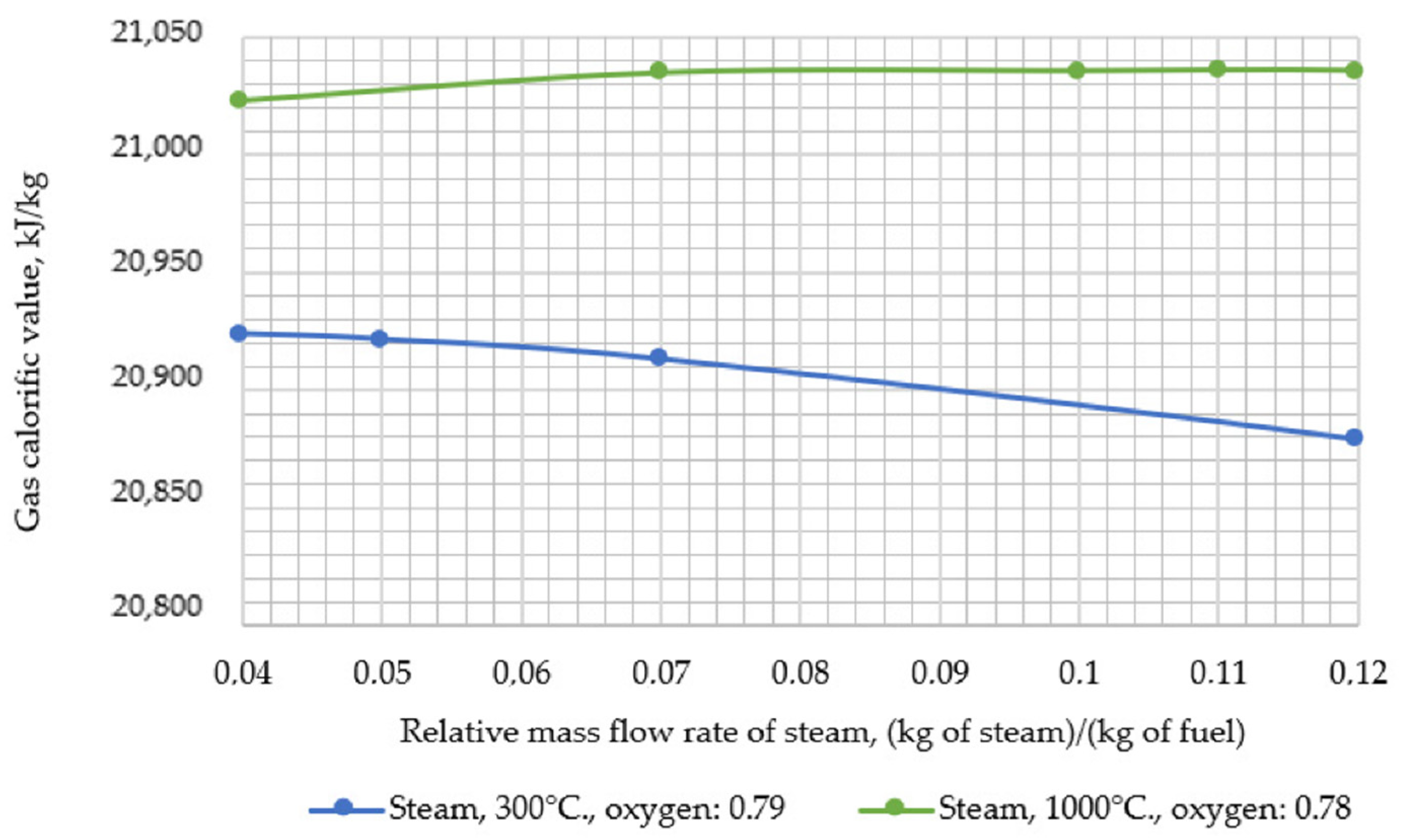
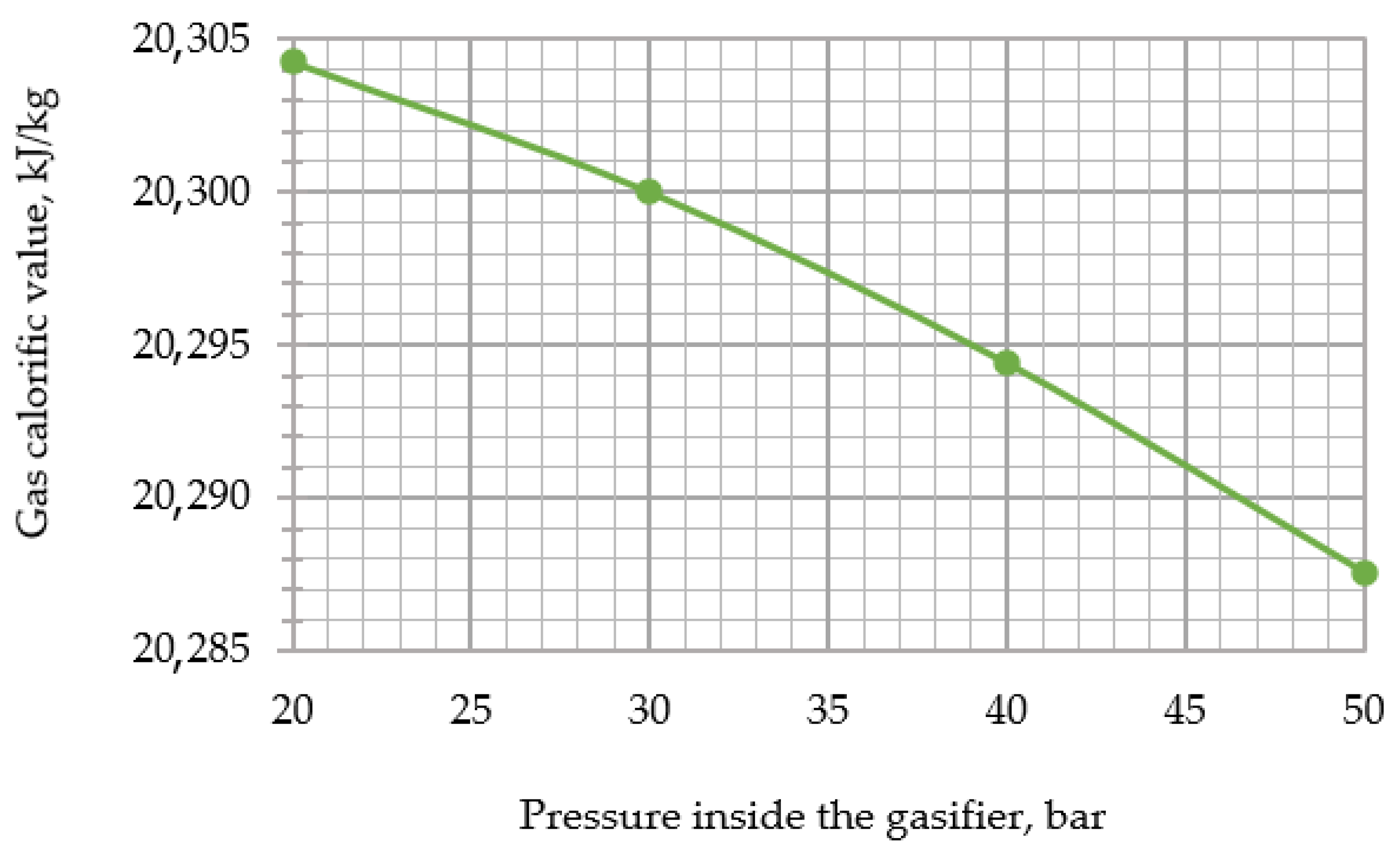
Thereafter, the developed model was used to assess the impact of changing the input parameters of the gasifier (i.e., temperature and relative mass flow rate of steam, temperature, and relative mass flow rate of oxygen and pressure) on the resulting output parameters (i.e., calorific value and temperature of the syngas). During the research, the following temperature values of steam supplied for gasification were assumed: 300, 450, 600, 750, 900, and 1000 °C.
Heat flow analysis of the CC with gasification included calculation of the syngas contents, LHV, and temperature using the above presented method. In general, the analysis includes computer simulation models of the cooled gas turbine, twin-flow heat recovery boiler, and steam turbine built using Aspen Plus software [28]. The working fluid thermophysical parameters were determined with high accuracy using the NIST Reference Fluid Thermodynamic and Transport Properties Database (REFPROP) [29].
The influence of the gasification technology on the cycle efficiency was evaluated for different stations of the steam bleeding into the gasifier steam turbine and the regenerative heat exchanger that uses the gasifier exit syngas heat. The calculation of thermal CCGTs with gasification is made using a set of developed mathematical models of power plants, including the model of an air separation plant, a gas generator model built using the MS Excel software package, and a CCGT model created using the Aspen Plus software package.
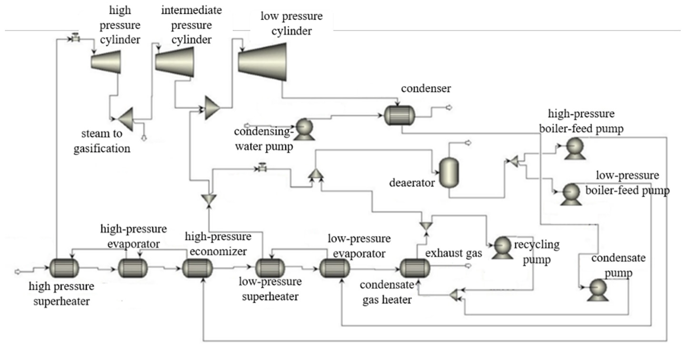
Figure 2 presents a CC with a gasification heat flow scheme simulated with Aspen Plus code. The facility includes a cooled gas turbine and a steam power facility with steam bleeding.
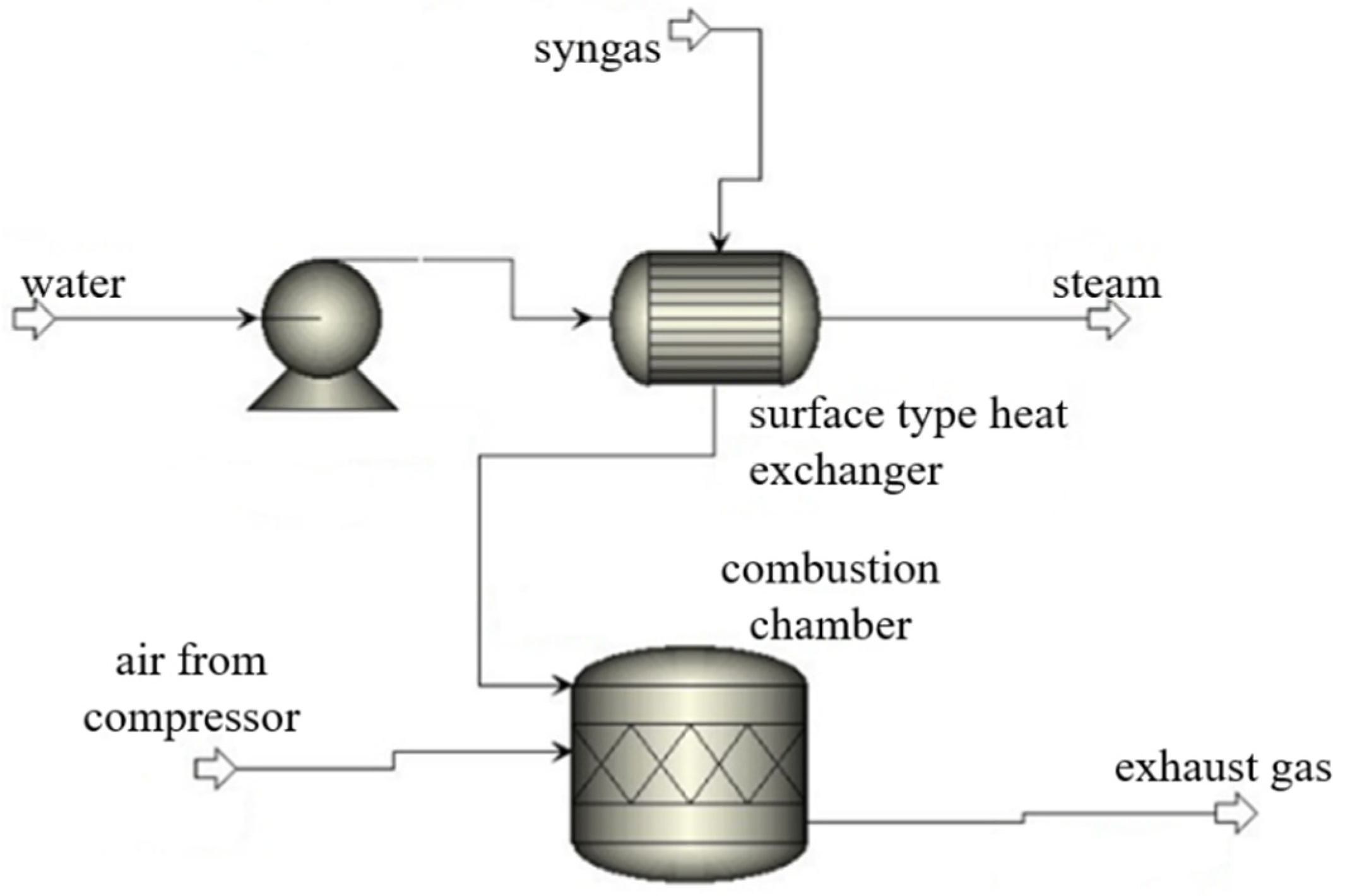
The cycle version without the steam bleeding from the steam turbine contains the steam production in a surface heat exchanger using the syngas heat. The surface heat exchanger is a new additional element (Figure 3). This study included the changes in the gasification steam flow and temperature that influence the heat exchanger exit temperature and the heat exchanger water flow.
The cycle computer simulation preceded the calculations of the main power production performance, as follows:
N MP = N ASP + N comp   O 2 + ( N KP + N CCP + N HPPP + N LPPP + N CRPP ) · η te η em ,
where NASP—ASU power consumption, MW; Ncomp O2—mechanical power of the ASU exit oxygen compressor that supplies compressed oxygen to the gasifier, MW; NKP—condensate pump mechanical power, MW; NCCP—condensate circulation pump mechanical power, MW; NHPPP—high pressure circuit feeding pump power, MW; NLPPP—low pressure circuit feeding pump power, MW; NCRPP—condensate recirculation pump power, MW; ηte heat transportation efficiency, %; ηem—electric motor efficiency, %.
N net   power = ( N GT N AC ) · η ep + N ST · η ep · η te N MP ,
where NGT—gas turbine mechanical power production, MW; NST—steam turbine mechanical power production, MW; and NAC—air compressor mechanical power consumption, MW; (the compressor is mounted on the gas turbine shaft. In the case of air combustion, it compresses the working fluid. In the case of oxygen combustion, it compresses the GT cooling air.); ηep—lectric power generator efficiency, %.
η net   power = N net   power B · Q ,
where Nnet power—cycle net power calculated by the equation (2.46), MW; B—coal fuel consumption, kg/s; and Q—coal fuel LHV, MJ/kg.

3. Results and Discussions

3.1. Influence of the Blow Type and Thermodynamic Properties of the Blast on the Composition and Heat of Combustion of Synthesis Gas

The calorific value of the syngas increases with a decrease in the relative mass flow rate of oxygen supplied for gasification, as can be seen from the dependence shown in Figure 4a. This is primarily because the volume fraction of CO and H2 in the syngas increased (Figure 4b).
The relative mass flow rate of oxygen supplied for gasification was optimized in the range of its values, not lower than 0.78 (kg of oxygen)/(kg of fuel). This value is a minimum allowable value that is sufficient to fix the entire amount of carbon in the source fuel. Based on the research in [29], this parameter may be minimized down to a value at which the sum of volume fractions of the CO and H2 components is the largest.
The dependence of the total volume fraction of carbon monoxide and diatomic hydrogen on the relative mass flow rate of oxygen is shown in Figure 4b.
With an increase in the amount of oxygen supplied for gasification, the total proportion of the CO and H2 components of the syngas at the output increases up to 0.79 (kg of oxygen)/(kg of fuel) and then decreases. This is due to an increase in the volume fraction of carbon monoxide in the synthesis gas to a maximum value. Oxygen binds most of the carbon contained in the fuel, and then it decreases due to an increase in carbon dioxide in the syngas, which receives the source carbon. At the same time, the volume fraction of hydrogen reaches its maximum value to further remain constant.
The developed model helps calculate specific volumes. The results of the analysis of calculations performed for the volume fraction of a mixture of carbon monoxide and hydrogen in the synthesis gas is shown in Figure 4b. This dependence helped to shift the equilibrium of chemical reactions with increasing steam temperature; as a result, the amount of oxygen that was needed to run the gasification process was also increased.
The optimal value of relative mass flow rate of oxygen for the steam temperatures under consideration, the values of composition by volume, temperature, and calorific value of the syngas, the volume fraction of the CO and H2 mixture, and the gasification efficiency are given in Table 6.
For further research, the steam temperature and the corresponding optimal value of the relative mass flow rate of oxygen were recorded, and the optimal values of the relative mass flow rates were chosen for the steam that was supplied to the gasifier. The dependence of the calorific value of the syngas on the relative mass flow rate of the steam is shown in Figure 5.
The output parameters for the fixed pair of steam temperatures and the corresponding relative mass flow rate of enriched oxygen are shown in Table 7.
With an increase in the temperature of the steam supplied for gasification, its consumption increases for the implementation of the gasification process with the same amount of fuel (kg of steam/kg of fuel). With an increase in the steam temperature, the specific volumes of reacting hydrogen and oxygen increase and, as a result, the specific total volume of the mixture of substances in the gas generator increases, which entails a shift in the equilibrium point of its chemical reactions. With an increases in the total mass flow of syngas (kg of syngas/kg of fuel), the specific heat capacity changes slightly.
At the final stage, there was a more complete assessment of the influence of synthesis gas input parameters on its output parameters. An analysis was made of the pressure maintained in the gasifier at a constant steam temperature of 415.15 °C, a relative mass flow rate of oxygen 0.84 (kg oxygen)/(kg fuel), and a relative mass flow rate of steam equal to 0.12 (kg steam)/(kg fuel). The dependence of the syngas calorific value on the gasification pressure is shown in Figure 6. With a decrease in gasification pressure, calorific value of the syngas grows, which is due to a changed composition of the products of syngas, as volume fractions of CO and H2 decrease, while CH4 grows, resulting in a lower calorific value of the syngas.
The calculation results show that with an increase in the temperature of the steam supplied for gasification, the relative steam consumption, referred to 1 kg of fuel, increases. At the same time, the amount of oxygen required for the reactions to proceed decreases. This can be explained as follows. With an increase in steam temperature, specific volumes of reacting hydrogen and oxygen increase and, as a result, the total specific volume of the mixture in the gasifier grows. This entails a displacement of the equilibrium of the chemical reactions occurring there.
An increase in steam pressure by 2.5 times leads to a decrease in the calorific value of synthesis gas by only 20 kJ/kg, which indicates the absence of a clear dependence of the calorific value on the pressure in the gasifier. The reaction constant of water–gas does not depend on pressure. The equilibrium of the methanation reaction shifts towards the formation of methane with an increase in pressure; however, the interaction of the carbon of the initial fuel with carbon dioxide and water vapor proceeds less intensively with an increase in pressure:
C + CO 2 2 C O ;   C + H 2 O C O + H 2

3.2. Efficiency of CC Cycle with Solid Fuel Gasification

The analysis described in point 3.1 allows for the assumption of the rate of oxygen supplied to the gasifier of 0.79 (kg oxygen)/(kg fuel). The analysis result summarized in Table 7 and Figure 3 shows low sensitivity of the syngas LHV upon the gasification steam temperature. The steam relative mass flow may be from 0.04 to 0.12 (kg of steam)/(kg of fuel), depending on temperature. The analysis included the following two sources of the gasification steam:
Steam turbine bleeding, with 35 bar pressure and 505 °C temperature;
Steam production in an additional recuperative heat exchanger, taking heat from the gasifier exit hot syngas.
Figure 7 shows dependence of the CC cycle on the solid fuel gasification net efficiency from the temperature and source of the gasification steam. In this figure, the green and blue columns show the turbine bleeding and the recuperator steam production, respectively.
The cycle efficiency is verified within 0.5%. Among the reviewed versions, the 505 °C steam bleeding from the turbine has the highest efficiency, and the cycle with 450 °C has the lowest efficiency. Small differences in the cycle efficiency values, depending on the steam temperature, are primarily due to the low dependence of the syngas combustion heat on the steam temperature. The change in the required steam flow rate in the gas generator on its temperature leads to the fact that the dependence of the cycle efficiency on the blast temperature has a non-linear dependence.
Figure 8 shows the power efficiency structure, including losses. According to thermodynamic analysis data, the heat losses for gasification are 11%.
At optimal parameters of the gasification steam, the cycle net efficiency reaches the level of 53.54%.

4. Conclusions

The described computer simulation model provides a relationship between the syngas contents and flow to the steam-oxygen blow parameters. The results strongly imply that the calorific value of the syngas can be increased by reducing the relative mass flow rate of oxygen; a decrease in the mass flow rate of oxygen by 1% entails an increase in the heat of combustion of the synthesis gas by 0.5%. In this case, it is necessary to ensure that the amount of oxygen supplied for gasification is enough to enable the gasification reactions. The value equal to 0.79 was determined by the authors as the optimum in terms of the content of combustible components and the autothermal nature of the gasification process.
Moreover, the calorific value of the syngas can be increased through an increase in the temperature of the steam supplied for gasification. Such an increase is insignificant: и is only 0.5–0.7% with an increase in steam temperature from 300 to 1000 °C; therefore, while increasing temperature of the supplied steam, it is necessary to monitor the value of the relative flow rate of the steam, which depends on temperature—the higher the temperature of the steam supplied for gasification, the more steam must be supplied. An excess of water steam leads to a decrease in temperature in the reduction zone, which weakens and may cause termination of the gasification process.
Finally, we obtained evidence that due to a decrease in working gasification pressure, the calorific value of the resulting syngas grows marginally; however a 2.5-fold decrease in the working pressure in the gas generator entails an increase in the calorific value of only 20 kJ/kg. A choice of a higher working pressure makes it possible to run the reactions faster and more efficiently, without a significant decrease in the calorific value of the gas, which in the future, might curb the expense of metal used to build a gasifier by reducing its overall dimensions.
Moreover, it allows for the thermodynamic analysis of the cycle versions. At optimal source and parameters of the gasification steam in the cycle of thermal efficiency may be as high as 53.54%. The cycle with steam bleeding from the turbine has the best efficiency. The cycle analysis shows the gasification related losses of 11%. It is worth mentioning that the CC with inter-cycle gasification efficiency is lower than the gas firing CC method, but higher than the solid fuel firing steam turbine methods.

Author Contributions

Conceptualization, I.K. and N.R.; Investigation, I.K., S.O., O.Z. and D.K.; Methodology, S.O.; Project administration, N.R. and O.Z.; Writing—original draft, S.O. and D.K.; Writing—review & editing, I.K., S.O. and D.K. All authors have read and agreed to the published version of the manuscript.

Funding

This study conducted by the Moscow Power Engineering Institute was financially supported by the Ministry of Science and Higher Education of the Russian Federation (project No. FSWF-2020-0020).

Data Availability Statement

Not applicable.

Acknowledgments

This study was conducted by the Moscow Power Engineering Institute and was financially supported by the Ministry of Science and Higher Education of the Russian Federation (project No. FSWF-2020-0020).

Conflicts of Interest

The authors declare no conflict of interest.

References

  1. Rogalev, N.; Prokhorov, V.; Rogalev, A.; Komarov, I.; Kindra, V. Steam boilers’ advanced constructive solutions for the ultra-supercritical power plants. Int. J. Appl. Eng. Res. 2016, 11, 9297–9306. [Google Scholar]
  2. Cormos, C. Integrated assessment of IGCC power generation technology with carbon capture and storage (CCS). Energy 2012, 42, 434–445. [Google Scholar] [CrossRef]
  3. Rogalev, A.; Kindra, V.; Osipov, S. Modeling methods for oxy-fuel combustion cycles with multicomponent working fluid. In AIP Conference Proceedings; AIP Publishing LLC: Melville, NY, USA, 2018; Volume 2047, p. 020020. [Google Scholar]
  4. Komarov, I.; Kharlamova, D.; Makhmutov, B.; Shabalova, S.; Kaplanovich, I. Natural gas-oxygen combustion in a super-critical carbon dioxide gas turbine combustor. E3S Web Conf. 2020, 178, 01027. [Google Scholar]
  5. Sadrtdinov, A.; Safin, R.; Gerasimov, M.; Petrov, V.; Gilfanov, K. The mathematical description of the gasification process of woody biomass in installations with a plasma heat source for producing synthesis gas. IOP Conf. Ser. Mater. Sci. Eng. 2016, 124, 8. [Google Scholar] [CrossRef] [Green Version]
  6. Mota, R.; Krishnamoorthy, G.; Dada, O.; Benson, S. Hydrogen rich syngas production from oxy-steam gasification of a lignite coal—A design and optimization study. Appl. Therm. Eng. 2015, 90, 13–22. [Google Scholar] [CrossRef] [Green Version]
  7. Schilling, G.; Bonn, B.; Kraus, U. Coal Gasification: Mining—Raw Materials—Energy (Translation from the German); Nedra: Moscow, Russia, 1986; 175p. [Google Scholar]
  8. Maistrenko, A.; Dudnik, A.; Yatskevich, S. Coal Gasification Technologies for Combined Cycle plants; Znanie: Kazan, Russia, 1993; 68p. [Google Scholar]
  9. Luque, R.; James, G. Speight Gasification for Synthetic Fuel Production: Fundamentals, Processes and Applications; Woodhead Publishing: Cambridge, UK, 2015. [Google Scholar]
  10. Abdullin, T.; Sabirzyanov, R.; Gilmanshin, L.; Kashapov, N.; Gilmanshina, S.; Galeeva, A.; Gadirova, E. About waste disposal problem in Russian Federation. IOP Conf. Ser. Mater. Sci. Eng. 2019, 570, 5. [Google Scholar] [CrossRef]
  11. Aizyzan, A.; Fedyukhin, A.; Strogonov, K.; Shaburov, E.; Kravchenko, S.; Kirillov, N.; Nikitkov, N.; Pankratov, Y.; Akhmetov, T. Modelling of the developed system for wood waste gasification. IOP Conf. Ser. Mater. Sci. Eng. 2019, 337, 9. [Google Scholar] [CrossRef]
  12. Zagrutdinov, R.; Nagornov, A.; Senachin, P.; Shitova, S. Performance indicators of gas generators of a dense layer of Lurgi with steam-oxygen and steam-air blast. Polzunovskii Vestn. 2008, 4, 28–33. [Google Scholar]
  13. Manovyan, A. Technology of Processing Natural Energy Carriers: Textbook; KolosS: Moscow, Russia, 2004; 456p. [Google Scholar]
  14. Mikhailov, V.; Khomenok, L.; Shestakov, N.; Leikam, A. Creation of unified power equipment for power units with intracycle gasification of solid fuel with a capacity of 200–300 MW. Mod. Sci. 2011, 3, 115–118. [Google Scholar]
  15. Thyssenkrupp Industrial Solutions [Electronic Resource]. Available online: www.thyssenkrupp-industrial-solutions.com (accessed on 15 November 2021).
  16. Alekseev, M.; Sorokin, A.; Shevyrev, S.; Gulev, A. Investigation of the Process of Hydrogen-Oxygen Steam Overheating in the Process of High-Temperature Steam Gasification of Solid Fuel; Vesti Kuzbass State Technical University: Kemerovo, Russia, 2012; pp. 102–105. [Google Scholar]
  17. Warnatz, J.; Maas, U.; Dibble, R.W.; Warnatz, J. Combustion. Physical and Chemical Fundamentals, Modeling, and Simulations, Experiments, Pollutant Formation; Springer: Berlin, Germany, 2006; 378p. [Google Scholar]
  18. Shevyrev, S.A.; Bogomolov, A.R. Conversion of Carbon-Containing Materials; News of the Kuzbass State Technical University: Kemerovo, Russia, 2011; pp. 91–98. [Google Scholar]
  19. Ryzhkov, A.F.; Filippov, P.S.; Bogatova, T.F. Analysis of the Work of Steam-Gas Plants with Intracycle Gasification of Coal: A Tutorial; Ural University Press: Yekaterinburg, Russia, 2019; 168p. [Google Scholar]
  20. Descamps, C.; Bouallou, C.; Kanniche, M. Efficiency of an integrated gasification combined cycle (IGCC) power plant including CO2 removal. Energy 2008, 33, 874–881. [Google Scholar] [CrossRef]
  21. Kler, A.M.; Marinchenko, A.Y.; Potanina, Y.M. Optimization Studies of a Combined-Cycle Plant with Coal Gasification and High-Temperature Heating of Blast Air; Proceedings of the Tomsk Polytechnic University: Tomsk, Russia, 2019; pp. 7–17. [Google Scholar]
  22. Ryzhkov, A.; Bogatova, T.; Gordeev, S. Technological solutions for an advanced IGCC plant. Fuel 2018, 214, 63–72. [Google Scholar] [CrossRef]
  23. Hannemann, F.; Schiffers, U.; Karg, J.; Kanaar, M. V94.2 Buggenum Experience and Improved Concepts for Syngas Applications; Gasification Technologies Conference: San Francisco, CA, USA, 2002. [Google Scholar]
  24. Promes, E.J.O.; Woudstra, T.; Schoenmakers, L.; Oldenbroek, V.; Thattai, A.T.; Aravind, P.V. Thermodynamic evaluation and experimental validation of 253 MW integrated coal gasification combined cycle power plant in Buggenum, Netherlands. Appl. Energy 2015, 155, 181–194. [Google Scholar] [CrossRef]
  25. Demin, A.; Dyganova, R.; Fakhreev, N. Thermo-chemical equilibrium modeling and simulation of biomass gasification. E3S Web Conf. 2020, 161, 01081. [Google Scholar] [CrossRef] [Green Version]
  26. Popov, S.; Ippolitov, V. Solving High-Temperature Thermal Engineering Problems in the Mathcad Environment: A Tutorial; Publishing House MEI: Moscow, Russia, 2009; 95p. [Google Scholar]
  27. Phillips, J. Different Types of Gasifiers and Their Integration with Gas Turbines: The Gas Turbine Handbook; US Department of Energy Publisher: Washington, DC, USA, 2006. [Google Scholar]
  28. AspenONE 10; Aspen Technology, Inc.: Bedford, MA, USA, 2018.
  29. Reference Fluid Thermodynamic and Transport Properties-REFPROP, Version 10.0; National Institute of Standards and Technology, Standard Reference Data Program: Gaithersburg, MD, USA, 2018.
Figure 1. Heat flow scheme of a CC facility with the steam–oxygen coal gasification. 1—air split unit; 2—oxygen compressor with inter-cooling; 3—gasification block; 4—air compressor for gas turbine cooling; 5—gas turbine combustor; 6—gas turbine; 7—electric power generator; 8, 11—high and low pressure steam superheaters; 9, 12—high and low pressure vaporizers; 10—high pressure economizer, 13—condensate gas heater; 14—steam turbine, 15—deaerator, 16—condenser, 17, 18—high and low pressure feeding pumps, 19—condensate pump, 20—condensate recirculation pump, 21—water supply to GT combustor pump.
Inventions 07 00065 g001
Figure 2. CC facility heat flow scheme simulated with Aspen Plus.
Inventions 07 00065 g002
Figure 3. Additional heat exchanger for the gasification steam production.
Inventions 07 00065 g003
Figure 4. Dependence of syngas output parameters from the relative mass flow rate of oxygen: (a) dependence of output parameters from the relative mass flow rate of oxygen; (b) dependence of volume fraction of CO + H2 from the relative mass flow rate of oxygen.
Inventions 07 00065 g004
Figure 5. Dependence of syngas calorific value on the relative mass flow rate of steam.
Inventions 07 00065 g005
Figure 6. Dependence of syngas calorific value on gasification pressure.
Inventions 07 00065 g006
Figure 7. Relationship of the cycle net efficiency to the gasification steam temperature.
Inventions 07 00065 g007
Figure 8. Power structure of the cycle with gasification steam bleeding from the turbine.
Inventions 07 00065 g008
Table 1. Comparison of solid fuel gasification methods.
Blow TypeSyngas Low Heating Value (LHV), MJ/m3Syngas ContentsNotes
Air blow3.5–4.8CO, CO2, H2, CH4, N2, resinsLarge amount of ballast gases, low LHV.
Oxygen blow10–15CO, CO2, H2, CH4, resinsNecessary comparison of expenses for the oxygen production balance by the better syngas quality.
Water steam blow12–20CO, CO2, H2, CH4, resinsAdditional power consumption for maintaining temperature in the gasification zone.
Table 2. Coal composition and thermal properties.
ParameterValue
Proximate analysis (%wt.)
Moisture (a.r.)8.10
Volatile matter (dry)28.51
Ultimate analysis (%wt. dry)
Carbon72.04
Hydrogen4.08
Nitrogen1.67
Oxygen7.36
Sulphur0.65
Chlorine0.01
Ash14.19
Table 3. Operation parameters of gasifier.
ParameterValue
Oxygen/coal ratio (kg/kg)0.84
Steam/coal ratio (kg/kg)0.12
Oxygen temperature, °C80
Steam temperature, °C415.15
Gasification pressure, bar40
Gasification temperature, °C1400
Table 4. Heat flow analysis input data.
ParameterValue
Ambient air temperature, °C15
Ambient air pressure, KPa 101.3
Turbine inlet temperature, °C1700
Cooling agent specific flow, %13.6
High pressure steam pressure, MPa 8.55
Low pressure steam pressure, MPa 0.7
Minimal temperature difference in high pressure superheaters, °C20
Minimal temperature difference in low pressure superheaters, °C20
Minimal temperature difference in high pressure vaporizer, °C50
Minimal temperature difference in low pressure vaporizer, °C10
Turbine exhaust pressure, KPa 4
Low pressure feeding pump exit pressure, MPa 0.9
High pressure feeding pump exit pressure, MPa 13
Condensate pump exit pressure, MPa 0.6
Condensate temperature at condensate gas heater inlet, °C60
Deaerator pressure, MPa 0.45
Under-heating to the deaerator saturation temperature at condensate gas heater exit, °C19
High pressure steam pressure, MPa 8.55
Table 5. Model calculation results, article data, and absolute error.
ParameterValue
ModelArticle DataAbsolute Error
Syngas temperature, °C1295.021400116.23
Volume composition of syngas, %CO24.5584.150.408
CO59.30157.162.141
H2O6.0996.590.491
H227.59626.221.376
N22.164.762.6
CH40.070.060.01
SO20.2160.20.016
Lower Heating Value, (kJ/kg dry)25,429.9627,803.292373.33
Table 6. Optimal values of output parameters for steam temperatures under consideration.
Steam Temperatures, °C3004506007509001000
Relative mass flow rate of oxygen, (kg of oxygen)/(kg of fuel)0.790.790.790.790.780.78
Volume composition of syngas, %CO24.084.013.943.883.753.69
CO60.160.160.260.260.460.5
H2O4.154.144.144.133.853.84
H228.428.528.628.728.628.7
N22.112.112.102.12.092.09
CH40.960.890.820.761.020.96
SO20.220.220.220.220.220.22
Syngas temperature, °C1122.61128.41134.81142.11124.71129.2
Syngas calorific value, kJ/kg20,879.120,893.020,906.620,919.421,024.521,035.7
CO + H2, %88.588.688.888.989.189.2
Table 7. Optimal values of output parameters for steam temperatures under consideration and corresponding relative mass flow rates of oxygen.
Steam Temperatures, °C3004506007509001000
Relative mass flow rate of oxygen, (kg of oxygen)/(kg of fuel)0.790.790.790.790.780.78
Relative mass flow rate of steam, (kg of steam)/(kg of fuel)0.030.030.040.050.080.11
Volume composition of syngas, %CO21.731.721.972.202.823.48
CO66.166.165.464.763.061.1
H2O1.641.641.902.162.753.56
H226.826.827.127.427.828.5
N22.242.242.222.22.152.10
CH41.251.241.151.061.221.02
SO20.230.230.230.230.230.22
Syngas temperature, °C1166.51168.21164.21162.21133.41131.0
Syngas calorific value, kJ/kg20,92520,92820,93320,93921,02921,036
Chemical gasification efficiency0.940.940.940.940.940.94
Thermal gasification efficiency0.8480.8440.8470.8470.8450.846
Publisher’s Note: MDPI stays neutral with regard to jurisdictional claims in published maps and institutional affiliations.

