1. Introduction
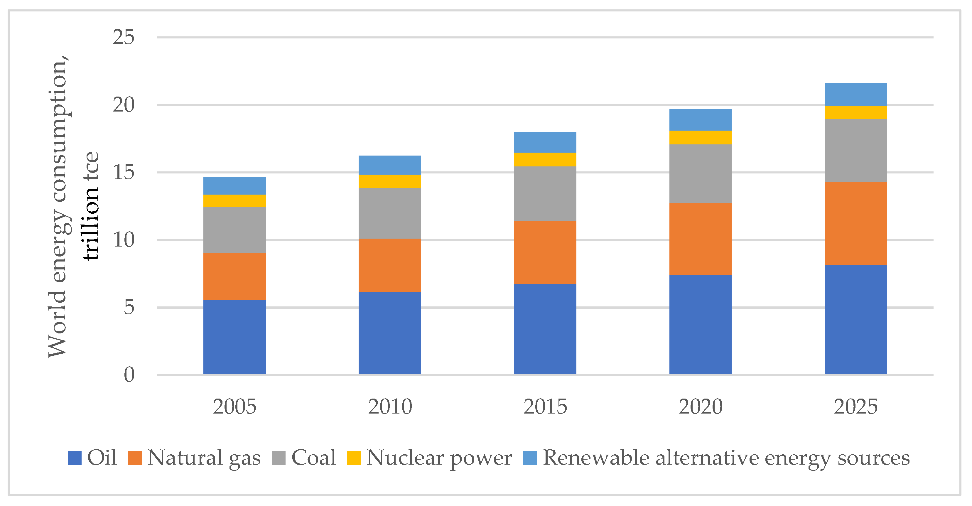
With the development of the world economy, there has been a continuous increase in electric power consumption due to both expanding and creating production facilities and increasing the power-to-labor ratio. The structural dynamics of the world energy consumption and its forecast up to 2025 by types of primary fuels are shown in
Figure 1.
As seen from the figure, the consumption of primary energy worldwide in the period from 2005 to 2020 increased by 20%; in 2025, additional growth of 5–7% can be expected [
1,
2,
3].
In the near future, an increase in world energy consumption along with depletion of oil and gas reserves could lead to a new global energy crisis, whereas the environmental problems arising from the use of fossil fuels can pose real threats to human survival. These objective facts in the development of modern civilization necessitate a transition to fundamentally new ways of energy consumption.
The existing demographic, environmental, scientific, engineering, and geopolitical factors lead to a gradual transition of national economies from using dwindling reserves of fossil fuels, which pollute the environment, to renewable, environmentally friendly energy sources. Thus, the forecast for the development of the Russian power economy in the long term shows that, by 2035, the situation shall require the use of new types of energy—artificial liquid fuel [
4,
5] and hydrogen [
6,
7]—in the national energy balance structure.
Over the past few years, it has become increasingly clear that the key trend in scientific and technological progress will be the transition from fossil fuels to hydrogen energy [
8,
9,
10]. This will provide a higher and more sustainable pace of economic development and reduce the risk of a global environmental catastrophe and irreversible climatic changes.
Hydrogen energy involves the use of hydrogen as the main energy carrier. The exceptional properties of hydrogen promise a wide range of applications in various fields of power engineering [
11,
12], including transport [
13] and industrial production [
14,
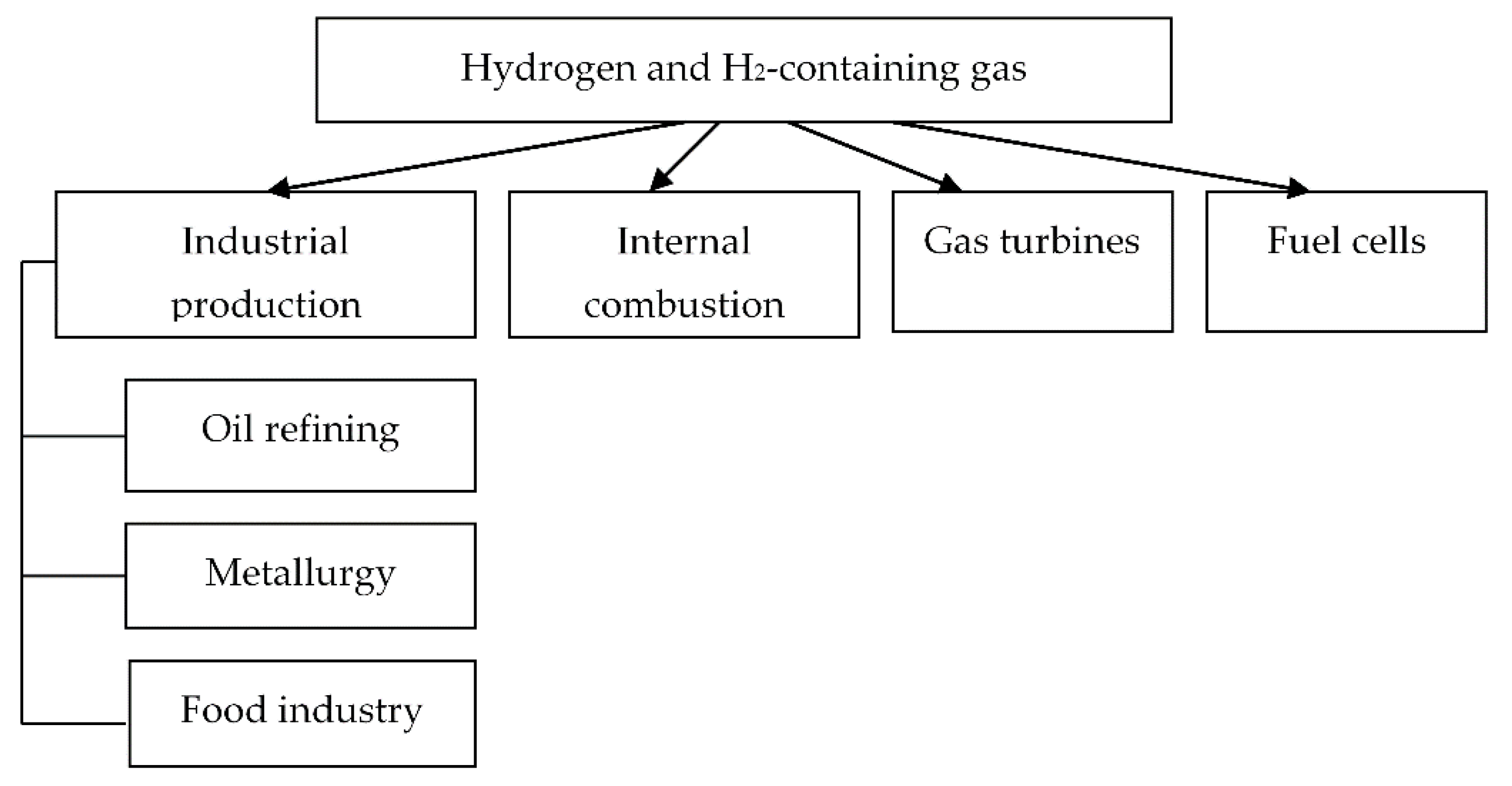
15]. The main hydrogen applications are shown in
Figure 2.
Hydrogen can be well used as a fuel in engines, autonomous power, and heat generators; it is convenient to use it for heat supply to distributed consumers, for energy transportation, and storage. It is also required in large amounts for oil refining in the chemical, metallurgical, construction, fuel, and food industries.
The transition of the national fuel and energy economy to the widespread use of hydrogen involves solving the following sectoral problems:
Launching a large-scale production of hydrogen from renewable and non-renewable energy sources;
Launching the manufacture of fuel cells and power plants based on the same;
Providing the storage and transportation of hydrogen;
Creating conditions to use hydrogen for energy generation in industrial production, transport, and everyday life;
Ensuring hydrogen safety.
In the future, the most important issue will be the use of hydrogen as a fuel. The important advantages of hydrogen as a promising fuel include the following:
Hydrogen is a source of energy that is not associated with the emission of any pollutants into the environment (when hydrogen is burned in pure oxygen, the only combustion products are heat and water);
The high calorific value of hydrogen fuel as compared with other fuels (
Table 1) [
16,
17].
The highest calorific value of hydrogen is 142 MJ/kg, which exceeds more than four times that of coal and 2.5 times that of natural gas. This is an important factor for its use in the production of electricity and heat at thermal power plants. Therefore, the idea of hydrogen being used in energy systems is widely considered in the scientific community. Thus, J. Milewski and M. Soufi studied thermodynamic cycles where hydrogen plays the role of the main fuel [
18,
19,
20,
21]. Y. Tsujikawa, T. Sawada, T.A. Miller, and K. Badyda described gas turbine and steam turbine power cycles using hydrogen in their studies [
22,
23]. R.Z. Aminov, A.N. Bayramov, and M.V. Garievskii considered the use of hydrogen in NPP cycles [
24,
25,
26].
At the same time, the main attention in previous studies was paid to providing steam overheating and its influence on the thermal efficiency of power plants using hydrogen as the main or additional type of fuel. However, these studies virtually did not consider the issues of accounting for additional energy costs associated with preparing hydrogen for combustion, which ultimately has a large impact on the overall efficiency of electricity generation in a power system. This paper pays special attention to this issue in the context of creating conditions for the transition to hydrogen energy. As the object of our research, we consider the use of hydrogen as a fuel in high-performance power plants, which is currently the most relevant and sought-after facility in electric power generation and essential for creating environmentally friendly and resource-saving energy systems.
2. Materials and Methods
2.1. Substantiating the Choice of the Industrial Hydrogen Production Method
One of the problems in the transition to hydrogen energy is the choice of the most efficient method for producing hydrogen.
Bound hydrogen is contained in water, several natural hydrocarbons, biomass, and various organic waste [
27,
28]. In order to produce hydrogen, it is necessary to break its chemical bonds and isolate it from the reaction medium.
The main methods for producing hydrogen are conventionally divided into physical, electrochemical, and chemical ones [
29,
30,
31]. Physical methods include those processes where the raw material (such as coke oven gas or gas produced by pyrolysis of butadiene) already contains free hydrogen, and we only need to extract it from the rest of the components in one way or another physical way. In electrochemical methods, hydrogen is released from its chemical compounds by decomposition of the latter under the effect of electric current. Chemical methods for producing hydrogen are the most common ones and involve incomplete oxidation (gasification, reforming) or thermal decomposition of fossil fuels.
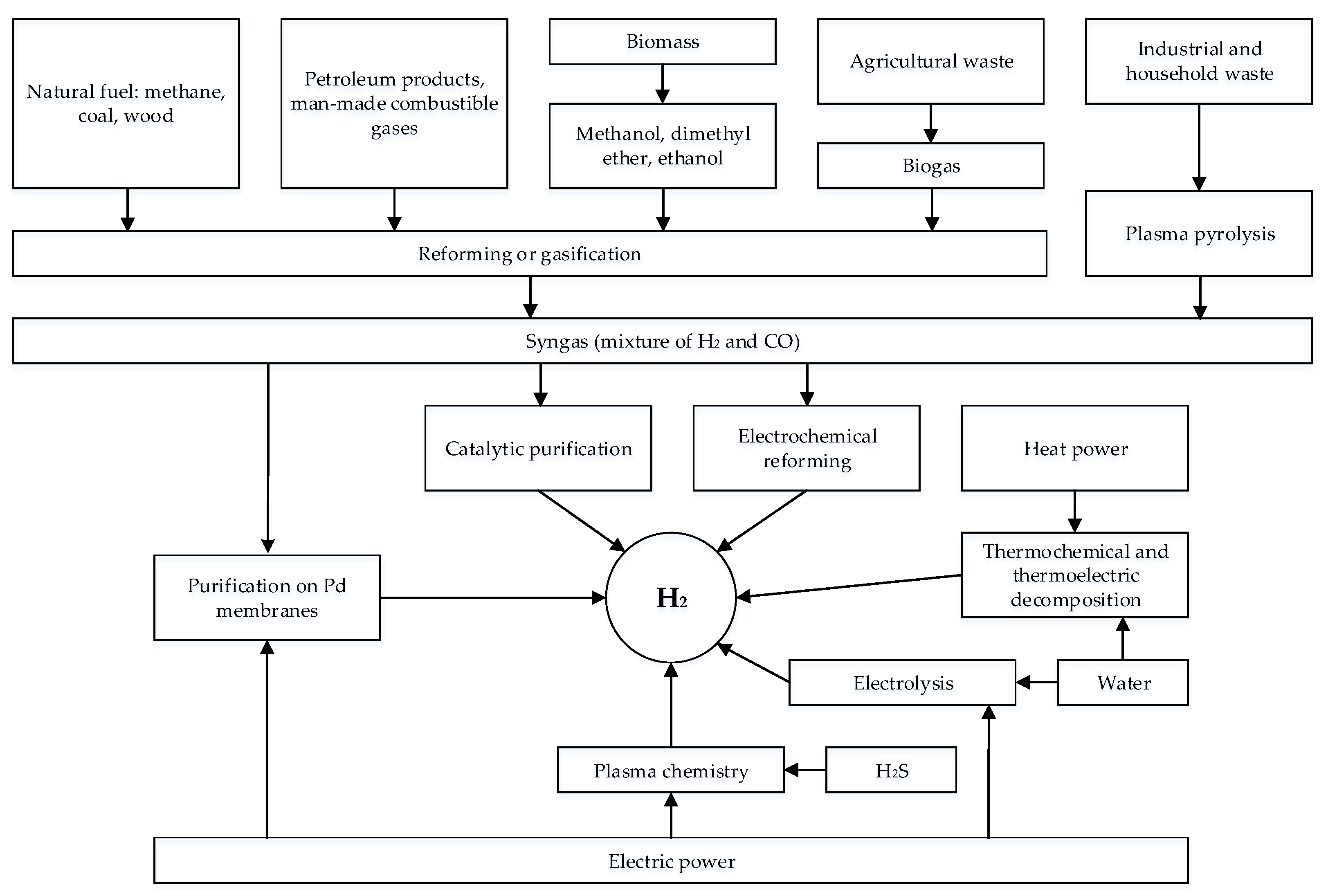
The most common hydrogen production methods are shown in
Figure 3. Among these methods, it can be water splitting, hydrocarbon reforming, coal gasification, and conversion of biomass and industrial waste, differing in the scale of hydrogen production and field of application.
Let us consider the process features of the main methods for producing hydrogen.
One of the best known and commercially developed methods with equipment available in the market is hydrogen production by electrolysis of aqueous solutions using electric power:
This method is also considered to be the most versatile since it uses a generally available and inexhaustible raw material: water. Its other advantages include:
High purity of the resulting hydrogen (up to 99.6–99.9%);
Simple and continuous process;
The possibility of producing valuable by-products—heavy water and oxygen [
31].
Along with these advantages, electrolysis has several drawbacks:
During electrolysis, most of the electricity is lost in the form of heat when current flows through the electrolyte;
The performance of modern, most efficient alkaline electrolyzers does not exceed 500 Nm3/h (for comparison, the performance of a standard small methane steam reformer is 10,000–40,000 Nm3/h).
The high specific consumption of expensive electric power in the electrolysis process determines the lower cost limit of the produced hydrogen. Even with a hypothetically achievable 80% efficiency of the electrolysis process, the complete absence of all other losses, “free” equipment and maintenance, the minimum cost of hydrogen (at an electricity price of USD three cents/kWh) cannot be lower than USD10.4/GJ, which is virtually equal to the hydrogen price in the modern market [
31,
32].
In general, the current price of hydrogen produced by electrolysis of water is within the range of USD22–USD45/GJ. The share of capital cost deductions in the production price for this method is a record low and amounts to 15–18%, whereas the price variation is mainly determined by differences in the cost of electric power and in the unit capacity of the plant [
31,
33].
Another well-known method for producing hydrogen is plasma chemistry based on the chemical activity of ionized gas–plasma [
34,
35].
Promising are non-equilibrium plasma–chemical systems, where electrons that are heated by an electromagnetic field to temperatures of 10,000–15,000 °C selectively transfer energy to molecules, whereas the latter, disintegrating, produce the required chemical compounds. In this case, the gas as a whole remains virtually cold (its temperature is 100–300 °C). An important advantage of these systems is the volumetric nature of the processes occurring in them. High rates of chemical reactions in the gas phase make it possible to achieve high specific productivity.
An ideal plasma–chemical object is carbon dioxide. The efficiency in the decomposition of carbon dioxide into carbon monoxide and oxygen exceeds 80%. Almost all of the energy supplied to the discharge can be used to implement a useful chemical reaction.
In addition, we can consider the use of hydrogen sulfide as a plasma–chemical object due to the problem of its emissions in gas fields. Dissociation of hydrogen sulfide in plasma generates two products: hydrogen and condensed sulfur.
Laboratory tests of this process have shown that energy consumption amounts to 0.85–1.0 kWh per cu.nm of hydrogen at a conversion rate of 45%. Such hydrogen is about 15 times cheaper than the electrolysis one; it can be widely used in power engineering and industrial production.
Much attention is paid today to the thermochemical method (direct thermolysis), which consists of the decomposition of water into hydrogen and oxygen at 2500 °C [
35,
36]. Such a high temperature limit has not yet been implemented at large process plants; therefore, researchers are striving to develop processes occurring in several stages, which would allow for producing hydrogen within temperature ranges below 1000 °C. The cost of hydrogen produced using thermochemical methods is 1.5–2 times higher than that of electrolysis hydrogen.
Much more promising is the method of steam reforming methane, which is currently fully mastered by the industry and has proven its commercial efficiency [
37,
38]. Reforming of gases means their processing in order to change the composition of the original gas mixture. Usually, gaseous hydrocarbons (methane and its homologs) and carbon monoxide are subjected to reforming to produce hydrogen or its mixture with carbon monoxide. Reforming is carried out using various reagents (oxygen, water vapor, carbon dioxide, and their mixtures) as oxidizing agents.
The most economical raw material for reforming is methane (natural gas). Currently, the steam reforming of methane (SCM) provides most of the commercially produced hydrogen.
In the SCM process, steam reacts with natural gas at high temperatures and moderate pressures (1.5–2 kgf/sq.m) in the presence of a nickel-containing catalyst (up to 20% Ni in the form of NiO). Steam and heat energy is required to separate hydrogen from the carbon base in methane.
The first stage in the SCM process is splitting methane and water steam into hydrogen and carbon monoxide:
Next, in the second stage, as a result of the “shift reaction”, carbon monoxide and water are converted into carbon dioxide and hydrogen. This reaction occurs at temperatures of 200–250 °C:
Currently, it is the cheapest (and most commonly used) industrial method to produce hydrogen. However, high temperatures are required to split methane; in addition, the reaction is accompanied by the emission of CO and CO2.
Another common method is hydrogen production from solid fossil fuels by gasification (processing together with water, steam, and air or oxygen) [
39,
40]. This method allows for converting the thermal energy of coal into the thermal energy of syngas with an efficiency of 98%.
To date, the thermal decomposition of coal is widely used in the coke chemical industry, where hydrogen is a by-product. However, hydrogen production from coal (using gasification, shift conversion of carbon monoxide with subsequent extraction of hydrogen from the gas mixture using various process methods) is much more expensive than its alternative production from natural gas. According to [
13], the increase in cost is at least 20%. Other important factors in the further increase in the price of hydrogen produced using this method are possible penalties for CO
2 emissions into the atmosphere. Obviously, when using coal, specific CO
2 emissions (per unit of produced hydrogen) will be several times higher than when producing hydrogen from natural gas.
The description of the considered basic methods for producing hydrogen is presented in summary in
Table 2.
As shown in our analysis of the process and economic features of hydrogen production methods for use in electric power generation, the following methods should be the most promising:
steam reforming of methane;
gasification and reforming of syngas;
electrolysis of aqueous solutions.
According to the data, these methods differ in the cost of hydrogen production (
Table 3) [
31,
33], environmental parameters [
35,
40], and additional capital investments (
Table 4) [
41,
42].
The coal gasification method has the least problems related to providing a raw material base, but currently, there are no high-power industry plants for these purposes. The method of steam reforming of hydrocarbons using methane as a raw material is best prepared for practical implementation for the needs of thermal power plants. Note that steam reforming of methane is not only the most widespread method but also the cheapest one for producing hydrogen.
From the point of view of reducing the carbon footprint, the most promising is the production of hydrogen by electrolysis. At thermal power plants, it is rational to produce hydrogen using electrolysis installations during the hours of electrical load dips when generating equipment is operating at nominal mode or using renewable energy sources, which will reduce the cost of electricity, increase efficiency and ensure low overall greenhouse gas emissions. The resulting hydrogen can be used for intermediate superheating of steam in high-temperature steam turbine power plants and for increasing the efficiency of a power plant. Thus, the needs of TPPs in primary carbon raw materials and, consequently, emissions of harmful substances into the atmosphere are reduced.
It can be concluded that electrolysis is currently the only way to produce hydrogen that can reduce greenhouse gas emissions. Other hydrogen production technologies result in life cycle greenhouse gas emissions similar to or even greater than those of fossil fuels. At the same time, hydrogen production using low-carbon technologies has historically been less economical and requires energy efficiency improvements and the creation of rational routes for the use of hydrogen, including in the production process of the power plant itself.
2.2. Developing a Technological Approach to Creating Highly Efficient High-Performance Power Plants Using Hydrogen
Today, steam turbine power plants, which, according to various estimates, generate up to 70% of the electricity consumed worldwide, are most commonly used at modern high-performance thermal and nuclear power plants [
43,
44,
45].
At the same time, the absolute efficiency of steam turbine power plants does not exceed 45%, which is explained by the fact that the initial steam temperatures for most steam turbine plants are about 540–560 °C, and only in some cases do they reach 600 °C. In this regard, we should search for solutions to further increase the initial parameters of the heat carrier, which will ensure the high efficiency of steam turbine power plants throughout the entire design service life of the equipment. Thus, with an increase in the initial steam pressure up to 32 MPa and its temperature up to 700 °C, the thermal efficiency of steam turbine power plants increases to 52%.
The most promising are the methods for external overheating of steam from an external source of thermal energy, which can be used in the near future to increase the performance and efficiency of thermal power plants operating at supercritical steam parameters with intermediate steam overheating [
45,
46]. In this case, it is advisable to abandon the intermediate steam overheating in a steam boiler and to isolate the intermediate overheater in a separate unit where any fuel, including hydrogen, can be used as the thermal energy source.
The advantage of such a process solution is the preservation of the boiler shop equipment unchanged. In the turbine shop, the existing medium pressure cylinders (MPC) are replaced with high-temperature MPC, and more powerful generators are installed.
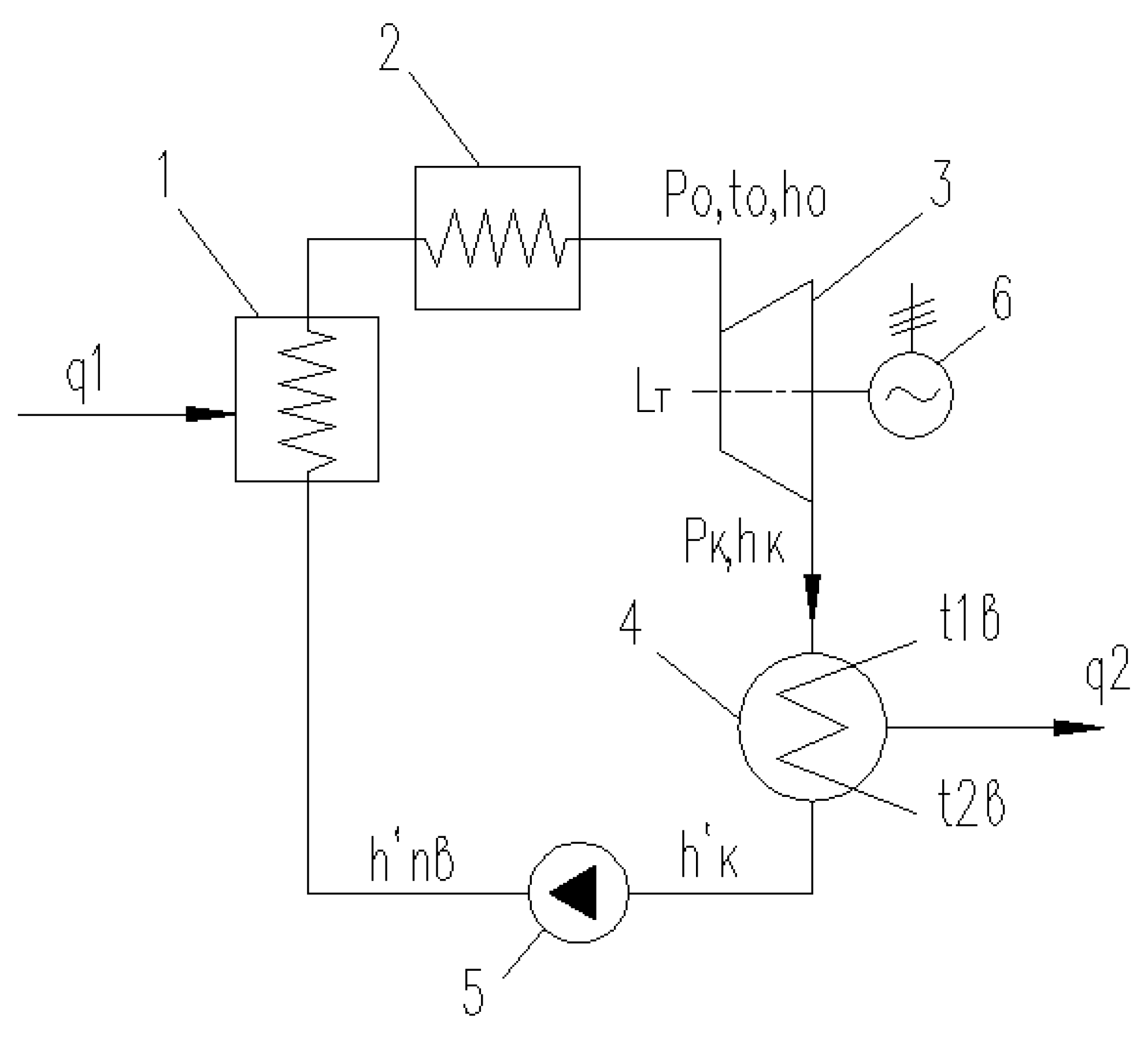
The simplest diagram of a steam turbine plant is shown in
Figure 4. It includes a boiler (steam generator) (1), an overheater (2), a turbine (3), a condenser (4), a feed pump (5), and an electric generator (6).
The main thermodynamic parameters of a steam turbine plant are given in
Table 5.
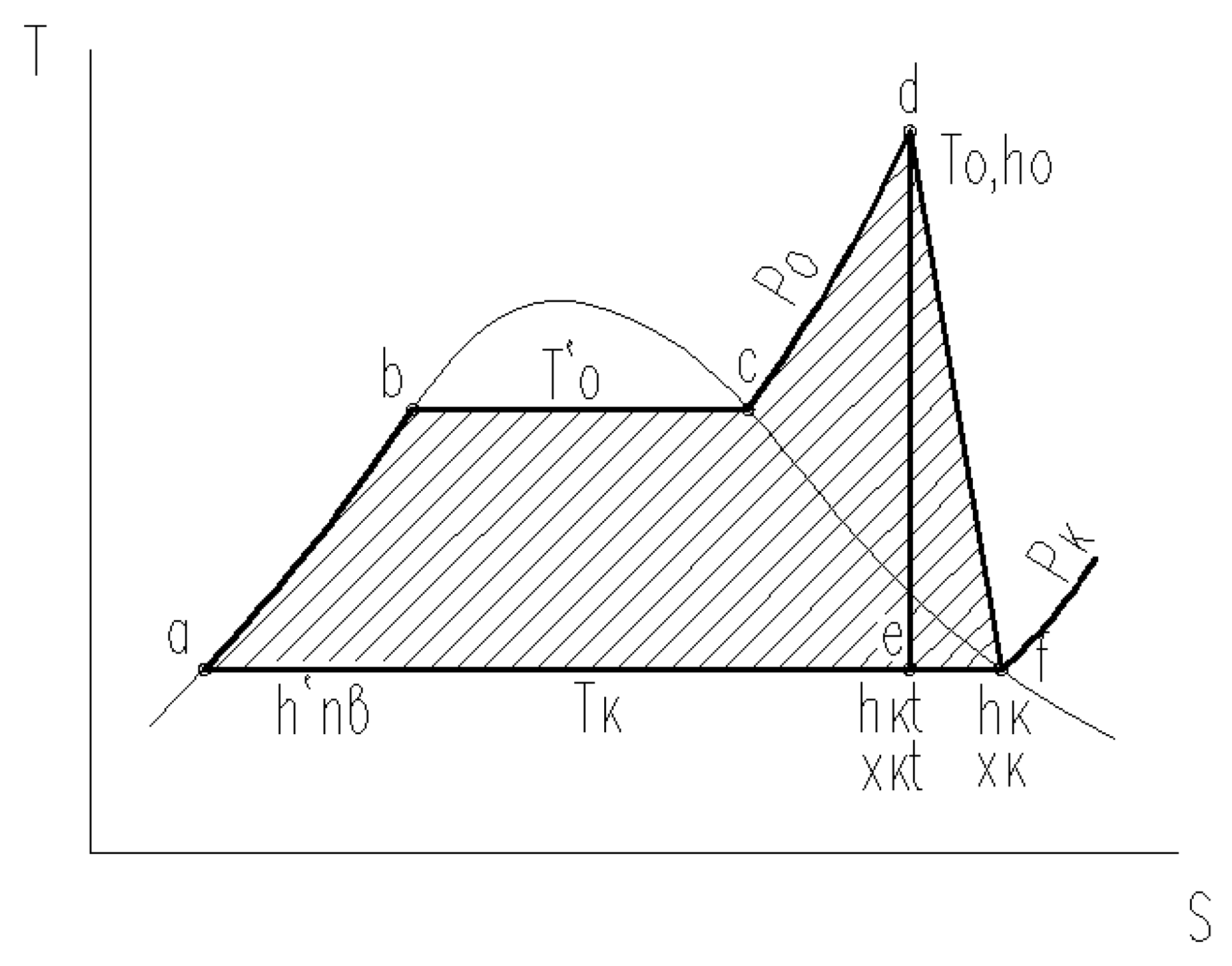
The thermal cycle of a steam turbine unit (Rankine cycle) is shown in
Figure 5.
In the above figure, point (a) corresponds to the state of the feed water upstream of the boiler. On segments (a)–(b) of the boundary curve, water in the boiler is heated to the saturation temperature T′0. On segments (b)–(c), water evaporates in the boiler at pressure P0. Next, on the isobar segment (P0 = const) (c)–(d), in an industrial overheater, the steam temperature is increased to the initial temperature T0, at which steam enters the turbine. The segments (d)–(e) corresponds to the steam expansion in the turbine in the absence of losses, whereas the line (d)–(f) describes the real process of steam expansion in the turbine. On segments (f)–(a), heat is removed in the turbine condenser at temperature Tc.
If the steam enthalpy is denoted at the end of the turbine in the absence of energy losses (an ideal cycle) through
hkt (point (
e)), enthalpy will increase up to
hk (point (
f)) due to losses in the turbine flow channel. As a result, the real specific work will be equal to
Lr =
h0 −
hk, whereas the specific work in the ideal cycle, to
Li =
h0 −
hkt. Therefore, the internal relative efficiency of the steam turbine can be defined as the following ratio:
Hence, the used enthalpy difference in the turbine will be equal to:
If we correlate the specific useful work (
Lr =
Hi =
h0 −
hkt) with the amount of specific heat (
q1 =
h0 −
hw), we can determine the absolute internal efficiency of the power plant from the following equation:
where
is the absolute thermal efficiency.
The above mathematical expressions and the heat cycle diagram clearly show that, with decreasing pressure
Pc in the condenser (temperature
Tc), the useful work (the shaded part of
Figure 5) increases and, therefore, the thermal efficiency of the cycle also increases.
Currently, the condenser pressure Pc rarely drops below 4 kPa. Based on this value, we will carry out the entire subsequent analysis of a possible increase in the power plant efficiency.
If, at a fixed initial temperature T0 and a constant temperature Tc, we increase the steam pressure P0, the available enthalpy difference H0 will grow up to a certain limit and, consequently, the thermal efficiency of the cycle will also increase. The higher the initial steam temperature T0, the higher the optimal initial steam pressure. However, the final steam humidity downstream of the turbine increases continuously. With the initial steam parameters t0 = 560 °C and P0 = 23.6 MPa, the final steam humidity will be 7%, and at t0 = 560 °C and P0 = 23.6 MPa − 24%.
The turbine operation with such a final steam humidity is impossible as an additional loss due to humidity will reduce the internal relative efficiency of the low-pressure cylinder by at least 20%, and, moreover, with such humidity, a long-term operation of the blade system is impossible due to erosive wear.
This problem of increasing the initial parameters of steam can be solved through its intermediate overheating [
46,
47]. When using it, steam downstream of the high-pressure cylinder (HPC) is resent to the boiler at the intermediate overheating pressure
Pnn, where its temperature
tnn is increased in most cases to the fresh steam temperature (
tnn =
t0). Next, after intermediate overheating, the steam expands in the medium- and low-pressure cylinders up to the design pressure in the condenser
Pc. Therefore, intermediate overheating allows reducing the final steam humidity and the end of the expansion process down to 7–10%.
The experience of operating condensing steam turbines has shown the possibility of a long-term operation of turbines at steam humidity values not exceeding 10–12% [
43,
48]. Essentially, in terms of thermodynamics, the use of intermediate overheating means supplementing the main steam turbine cycle with an additional cycle that features a higher value of the equivalent starting temperature. Accordingly, the overall absolute efficiency of the steam turbine plant increases.
Upon introducing the intermediate steam overheating, the thermal efficiency of the steam turbine cycle will be determined by the following ratio:
where
h1t is the steam enthalpy downstream of the high-pressure cylinder in the absence of energy losses in the turbine flow channel (the ideal cycle);
h′
w is the feed water enthalpy;
hnn is the steam enthalpy after intermediate overheating;
is the enthalpy difference in the high-pressure cylinder.
3. Results
The assessment of the effect provided by intermediate overheating on the thermal efficiency of the cycle in turbines operating at supercritical steam parameters at the initial pressure
P0 = 23.5 MPa and the initial temperature
t0 = 560 °C is given in
Table 6. For standard turbines of this type (K-300-240, K-800-240), the steam pressure after intermediate overheating is equal to 3.42 MPa at the temperature
tnn = 540 °C. The steam pressure downstream of the turbine is assumed to be
Pc = 4 kPa.
Therefore, upon introducing the intermediate overheating, the thermal efficiency of the cycle is increased by 1.37%, the theoretical specific work of the turbine (/H0), by 24%, and the final steam humidity is significantly reduced from ykt = 27.4% to ykt = 14.8%.
The latter fact is very important since each percentage of humidity reduces the internal relative efficiency of a turbine stage by about 0.8%. As a result, the low-pressure cylinder efficiency, in the absence of intermediate overheating for the conditions under consideration, is about 6% lower than that of a turbine with intermediate steam overheating. In addition, with the steam humidity yκ > 10%, there is intense erosive wear on the blade system, and the service life of the low-pressure turbine cylinder is drastically reduced.
If we compare the considered cycles, not in terms of thermal efficiency but in terms of absolute efficiency
ηi, taking into account the actual efficiency of the cylinders, we obtain the following advantage from using intermediate overheating:
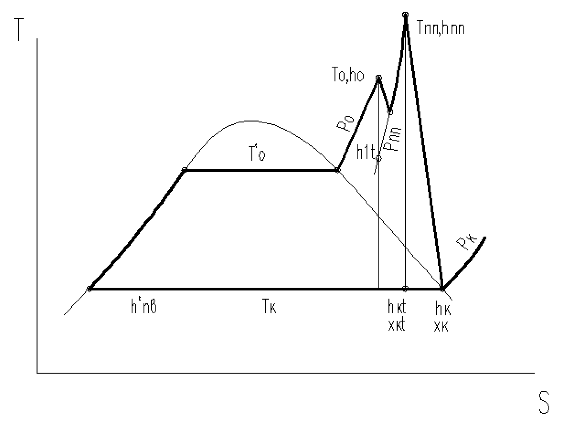
The advantage of using intermediate steam overheating can be even more important if we increase the temperature after intermediate overheating to a value at which the steam humidity downstream of the last turbine stages will be zero (dry saturated steam). This condition for the assumed initial steam parameters corresponds to the steam temperature after intermediate overheating equal to
tnn = 780 °C. Then, the thermal process in a steam turbine will look like the h-s diagram, as shown in
Figure 6.
In this case, the thermal and absolute efficiency of the cycle can be calculated using the following formulas:
The enthalpy, thermal and absolute efficiency values of the cycle with increasing temperature after intermediate overheating are given in
Table 7.
Therefore, when using high-temperature intermediate steam overheating, we can increase the steam turbine cycle efficiency by 2.5% against the existing level. When taking into account the regenerative heating of water, the absolute efficiency of the cycle can be increased by up to 50%:
where
is the coefficient that takes into account the increase in efficiency due to the regenerative steam heating.
It can be noted that the resulting absolute efficiency of the cycle is close, in terms of magnitude, to the absolute efficiency of steam–gas plants operating at significantly higher initial temperatures of the working fluid (t0 = 1300–1350 °C).
In addition, simultaneously with an increase in efficiency, as noted above, upon introducing high-temperature intermediate steam overheating, there is also a 21% increase in the total available enthalpy difference for the entire turbine. In other words, we also achieve an increase in the turbine performance without increasing the steam consumption by 21%. When using the above intermediate steam overheating for the K-800-240 turbine, its performance can be increased to 960 MW by replacing the existing medium-pressure cylinder with a new high-temperature MPC.
The most promising source of thermal energy for high-temperature overheating of steam is hydrogen. It will not only allow an increase in the steam turbine cycle efficiency but also ensure the environmental friendliness of electric power generation [
20,
49,
50].
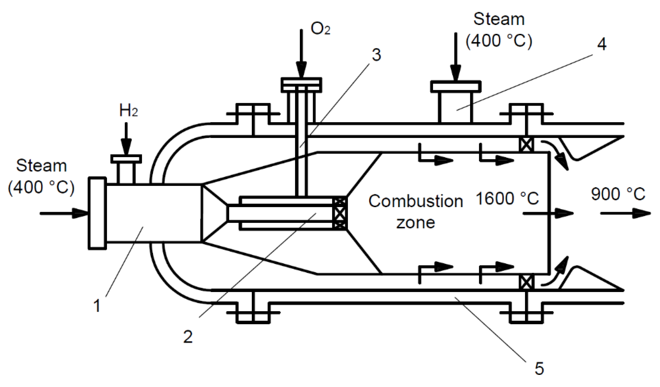
In the first stage, hydrogen fuel can be used to overheat steam in steam turbine units. The main feature of such steam overheating is the process of burning hydrogen directly in the steam environment. In terms of technology, this problem is not particularly difficult, as it can be solved by using combustion chambers similar to those of gas turbine engines. One possible solution is shown in
Figure 7.
At the inlet, there is a mixing chamber (1), where steam that is overheated to 400 °C and hydrogen are supplied. Then, this mixture is fed to the burner (2). The oxygen that is necessary for combustion is also supplied there through a channel (3). As a result of combustion, steam overheated to 1600 °C is produced and then mixed with “cold” steam that is supplied through the branch pipe (4) into the combustion chamber body (5). The steam temperature downstream of the combustion chamber is determined by the amount of hydrogen supplied to the mixing chamber and the flow rate of “cold” steam supplied to the combustion chamber body.
As in the case of gas turbines, the steam flow after the combustion chamber is higher than the steam flow supplied thereto by the amount of additional steam generated during the hydrogen combustion.
The required amount of hydrogen for use as a fuel for intermediate overheating at TPPs can be determined using the following heat balance equation:
where
B is the mass consumption of hydrogen required to overheat 1 kg of steam;
Qp is the heat dissipation capacity of 1 kg of hydrogen;
ηcc is the combustion chamber efficiency;
β = 9
B is the amount of steam generated when burning
B kg of hydrogen.
Hence, for the K-800-240 turbine manufactured by Power Machines, JSC with enthalpy values
hnn = 4097.6 kJ/kg,
h1 = 2960 kJ/kg, taking into account the heat dissipation capacity of hydrogen
Qp = 120,133 kJ/kg and the combustion chamber efficiency
ηcc = 0.96, we obtain the following consumption of hydrogen fuel:
At the above hydrogen consumption in the combustion chamber, an additional amount
β = 9
B = 0.147 kg/s of overheated steam is generated with enthalpy
hnn = 4097.6 kJ/kg. Therefore, after burning hydrogen in the combustion chamber, the steam flow through the high-temperature medium-pressure cylinder of the turbine increases by almost 15%. As a result, the absolute cycle efficiency reaches 48%:
When using regenerative heating of feed water, the efficiency of the cycle increases to 54%:
Our estimates clearly indicate the high efficiency of using hydrogen fuel for high-temperature steam overheating downstream of the high-pressure cylinder. In this case, at an overheating temperature equal to tnn = 760 °C, the absolute efficiency of the cycle is virtually equal to that of a CCGT unit operating at the initial gas temperature t0 = 1350 °C.
At the same time, while maintaining the boiler capacity, the rated performance of the power plant increases by 12%. When assessing the increase in the power plant performance due to the increase in steam consumption through the MPC and LPC, it should be borne in mind that the enthalpy difference in these cylinders is about 80% of the total enthalpy difference for the entire turbine.
Due to the fact that hydrogen combustion occurs in a steam environment, the pressure of the reaction components should slightly exceed the pressure of the main flow. This means that, in order to supply hydrogen and oxygen to the combustion chamber, it is necessary to pre-compress them to a pressure higher than that in the steam line where the combustion chamber is installed. The compression work for gases can be calculated using the following formula:
where
k = 1.4 is the adiabatic exponent;
R is the gas constant;
T1 is the compression start temperature;
P1 =
Pnn,
P2 is pressure at the beginning (taking into account the intermediate overheating) and at the end of the process.
To estimate the power consumption, let us take the gas constant for hydrogen and oxygen as = 4124 J/kg∙K, = 259.8 J/kg∙K. At the same time, we assume that the final pressure P2 increases by 5% of the required pressure Pnn for the case of installing the combustion chamber in intermediate overheating steam (P2 = 1.05Pnn).
The power (
Nc) consumed for oxygen and hydrogen compression can be found by multiplying the corresponding work of the process by the flow rate of the working fluid and by dividing the product by the compression efficiency (
ηc):
where
ηc = 0.8, which reflects the value of the average efficiency of most compression machines.
Accordingly, the total compression power (
) can be defined by the corresponding required power values separately for hydrogen and oxygen:
It is convenient to represent the dependence of the power consumption for the hydrogen and oxygen compression as a relation to the electric power of the power plant
Ne:
The flow rate of the working fluid
m is determined by the additional hydrogen overheating Δ
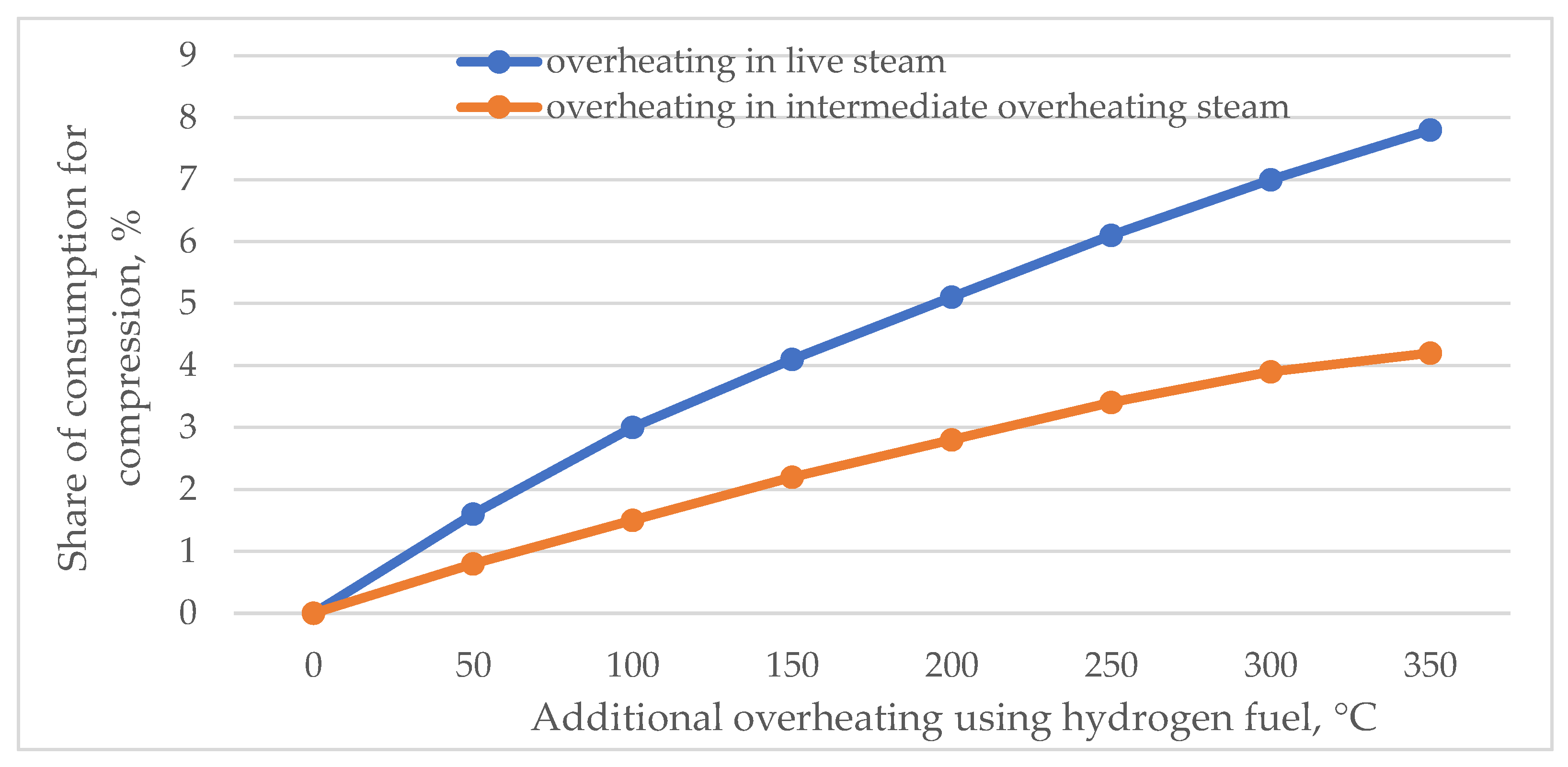
tnn at the installation place of the combustion chamber. The calculation of the additional share of power consumed for the plant auxiliaries (
E) depending on Δ
tnn at fixed values of live steam pressures (
P0 = 24 MPa) and the intermediate overheating steam (
Pnn = 3.6 MPa) is shown in
Figure 8.
In the case of installing the combustion chamber in live steam at Δtnn = 300 °C, the share of additional power consumption for auxiliaries should be E = 7% and at intermediate overheating E = 3.9%.
The largest share of the total additional power () falls on the power consumed for hydrogen compression (), which amounts to 94%. Hence, it can be concluded that measures that reduce the power consumption for auxiliaries should be taken mainly for the hydrogen compression process.
The conducted study explains the new property of hybrid power units, which is not typical for traditional power plants: a significant dependence of power consumption for auxiliaries on the initial temperature.
4. Discussion
In order to evaluate the cost-effectiveness of hydrogen production at a TPP and its use for reheating steam in high-temperature steam turbine power plants, Nel Hydrogen electrolyzers were selected, designed to meet the needs of industrial applications of hydrogen with a high degree of purity.
These electrolyzers are based on proto-exchange membrane (PEM) technology. Gaseous hydrogen is formed at the cathode at a pressure of 30 bar, and oxygen is formed at the anode at a pressure close to atmospheric. The separating membrane prevents oxygen from entering the hydrogen stream. The technical characteristics of the electrolysis installation are presented in
Table 8.
The capital and operating costs for the installation and operation of the electrolyzer are USD 7,900,000 and USD 395,000 per year, respectively (5% of capital costs).
The service life of the high-temperature steam turbine was chosen to be 15 years. In accordance with the technical characteristics of the electrolyzer, when operating in the nominal mode, 85% of the time during this period, 8,280,390 kg of hydrogen will be produced with maximum power consumption.
Specific costs for hydrogen production are calculated as total capital and operating costs for 15 years divided by the amount of hydrogen produced. Thus, they will amount P1 = 1.75 USD/kg.
The cost of electricity P2, spent on the production of hydrogen, will be determined as the product of the cost of electricity (USD/kWh) generated at the TPP by the electricity consumption of the electrolysis installation (kWh/kg).
Thus, the cost of hydrogen production P will be determined as the sum of the costs of hydrogen production P1 and the cost of electricity P2 consumed by the electrolysis installation, P ≥ P1.
A TPP, which is supposed to use a highly efficient steam turbine using hydrogen, and an electrolysis installation for its production, is being considered Iriklinskaya GRES, which is one of the largest thermal power plants in the Urals. The installed electric power of the TPP is 2400 MW, and the heat power is 120 Gcal/h. The plant annually generates 11,638 million kWh, while its specific reference fuel consumption for the supply of electrical energy is 331.6 g/kWh, and for the supply of heat—173.6 kg/Gcal. The annual supply of heat is 122.48 thousand Gcal. The production capacities of TPP operate in cogeneration mode, providing economical production of heat and electricity in a single cycle.
Let us assume that during the cold months, most of the power of the cogeneration turbines is spent on heat production. In this case, electricity will be a by-product and, during power dip hours, will be spent on the production of hydrogen in the electrolysis installation. At the same time, the costs of its production will be fully attributed to heat, and the price of hydrogen will be determined only by specific costs P1.
In other months, the cost of hydrogen production will already be determined by the change in the cost of electricity at TPP. The cost of electricity will reach its maximum value in the summer period when heat power is not produced in cogeneration mode, and all costs are attributed to electricity production.
Furthermore, suppose that hydrogen is produced uniformly in the electrolysis installation (hydrogen is not stored in large volumes) and then it is usefully and efficiently spent for the needs of intermediate overheating of steam in a high-temperature steam turbine. Previous calculations showed that the consumption of hydrogen fuel in the combustion chamber is 0.016 kg/s = 57.6 kg/h = 1382.4 kg/day.
Depending on the cost of electricity, it is possible to determine the structure of the cost of hydrogen production at various costs for electricity and with the expected power consumption of the electrolyzer (
Table 9).
The economic effect of the production and use of hydrogen at TPP in the high-temperature steam turbine will be determined by the difference between income and expenses.
The profitable part will be formed from the resulting fuel savings during the intermediate superheating of steam with hydrogen due to an increase in the efficiency of TPP by 2.5%. Based on the specific fuel consumption of 374 g.c.e./kWh, the average natural gas price in 2022 is USD110/ths. m3 (in the Urals economic region), fuel savings in monetary terms will amount to USD 2.86 million per year.
The NPV of the project amounted to USD 1.08 million at a discount rate of 12% and a project implementation period of 15 years. The payback period of the project is 12 years. Thus, the production of hydrogen in electrolysis installations at TPP and its use in a high-temperature steam turbine is cost-effective.
It should also be noted that when natural gas is replaced by hydrogen, the combustion of each ton of hydrogen will reduce CO2 emissions by 6.8 tons, and an increase in plant efficiency by 2.5% due to intermediate overheating of hydrogen fuel will reduce specific CO2 emissions by approximately 25 kg/MWh.
5. Conclusions
The limited world reserves of primary raw materials, along with the need to comply with environmental standards while meeting the ever-increasing demand for energy resources, raises the question of improving the efficiency of electricity production, most of which is produced in thermal power plants that burn fossil fuels. In this regard, many scientific studies are aimed at improving the efficiency and environmental friendliness of traditional steam turbine power plants. At the same time, there is a clear trend towards the use of unconventional energy sources and alternative types of energy resources, including hydrogen fuel.
One of the problems in the transition to hydrogen fuel is the choice of the most efficient method for industrial hydrogen production. Our analysis of the process and economic specifics of producing hydrogen to be used in electric power generation showed that the most promising are the methods of steam reforming of methane, gasification and reforming of syngas, and electrolysis of aqueous solutions. The most suitable method for practical implementation for the needs of TPPs is the electrolysis method, which makes it possible to obtain inexpensive hydrogen due to the released electrical power during the hours of electrical load dip.
The main opportunity to significantly increase the efficiency and environmental friendliness of electricity generation at TPPs is to significantly increase the initial parameters of the steam turbine cycle. Introducing additional hydrogen overheating directly upstream of the steam turbine in special combustion chambers, where hydrogen is burned in a steam-oxygen environment, is one of the promising solutions. On the one hand, such an approach will significantly increase the initial steam temperature, and, on the other hand, it will minimize the area of structural elements operating in the ultra-high temperature range, thereby reducing the use of expensive heat-resistant materials.
The study has shown that, upon introducing intermediate overheating, the thermal efficiency of the cycle is increased by 1.37%, and the theoretical specific work of the turbine is increased by 24%. The study also found that the advantage of intermediate steam overheating can be even more significant if the temperature after intermediate overheating is raised to a value at which there is no moisture in the steam downstream of the last turbine stages (dry saturated steam). Therefore, high-temperature intermediate steam overheating can increase the efficiency of the steam-turbine cycle by 2.5% against the existing level and, taking into account regenerative water heating, and the absolute cycle efficiency can be increased up to 50%.
At the same time, to supply hydrogen and oxygen to the combustion chamber, it is necessary to pre-compress them to a pressure greater than the pressure in the steam line on which the combustion chamber is installed. It is shown that the share of additional power costs for own needs will be 7% and more.
An economic analysis of the process of hydrogen production at TPPs by electrolysis and its further use for intermediate overheating in steam turbines in order to increase their efficiency showed the effectiveness of this solution in the case of using cheap electricity generated during hours of low demand for electricity, or heat cogeneration and electricity when electricity costs can be attributed to the generated heat.


