
Feasibility Study of the CO2 Regenerator Parameters for Oxy-Fuel Combustion Power Cycle


Abstract
:1. Introduction
1.1. Low-Carbon Power Production
1.2. Oxy-Fuel Combustion Technology Challenge
1.3. Thermal-Hydraulic Characteristics for PCHE Heat Exchangers
2. Materials and Methods
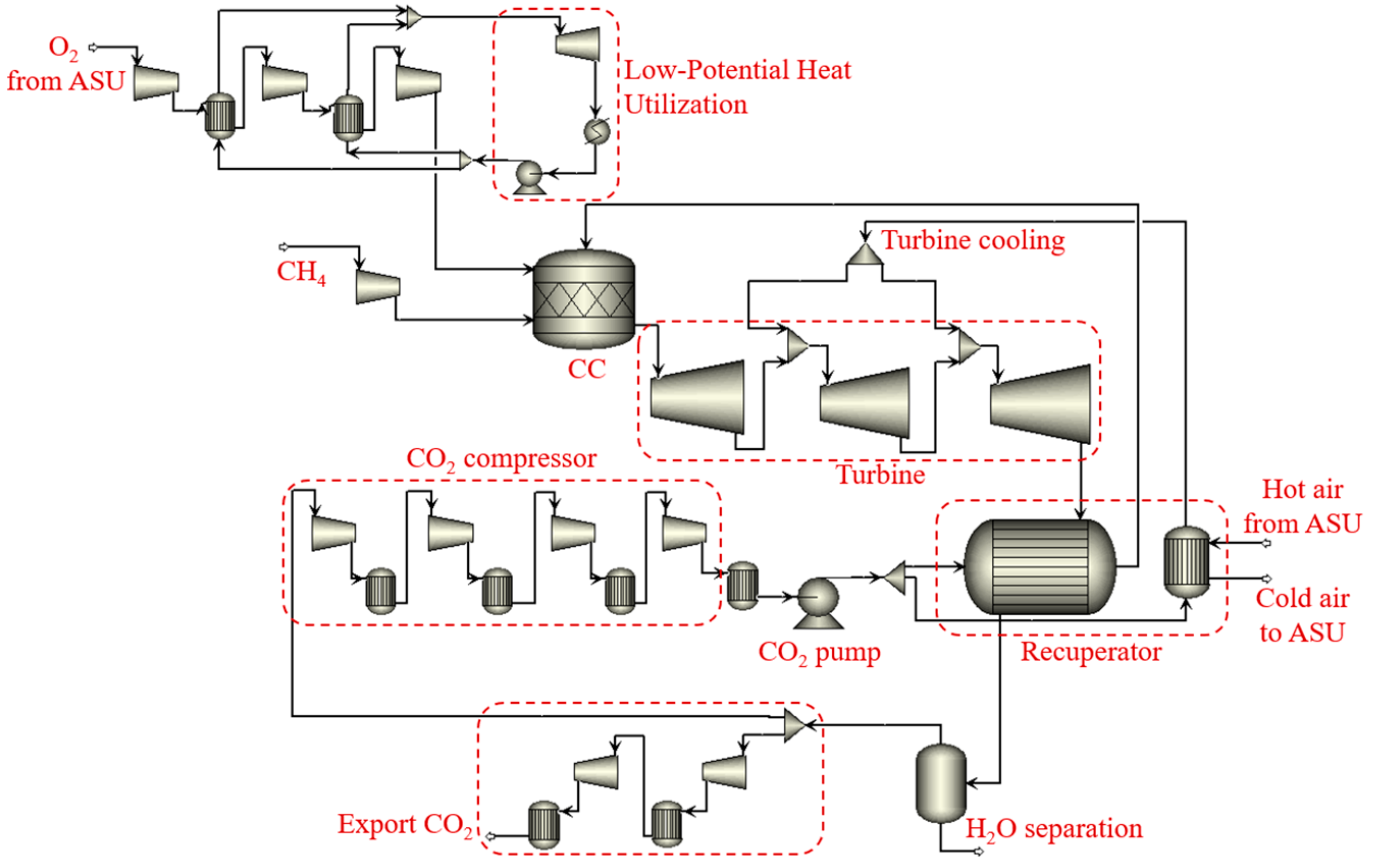
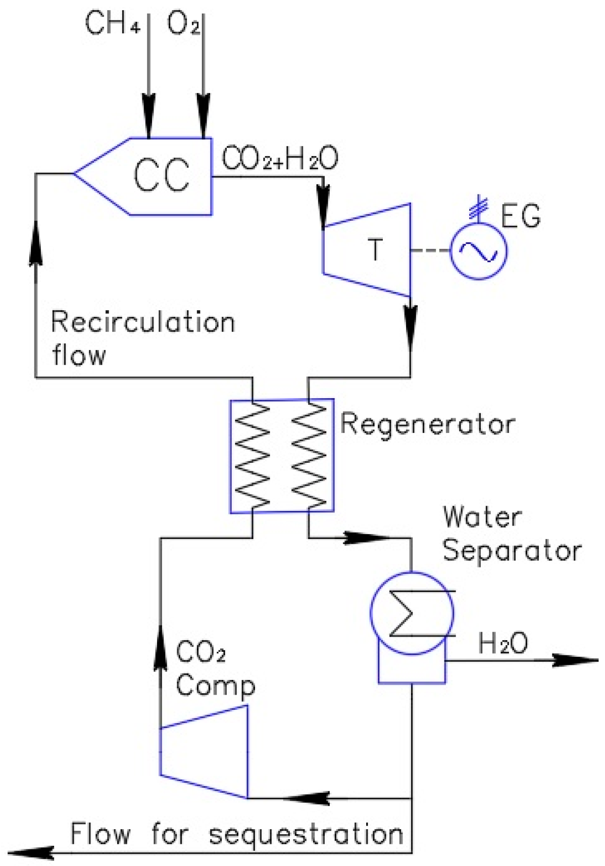
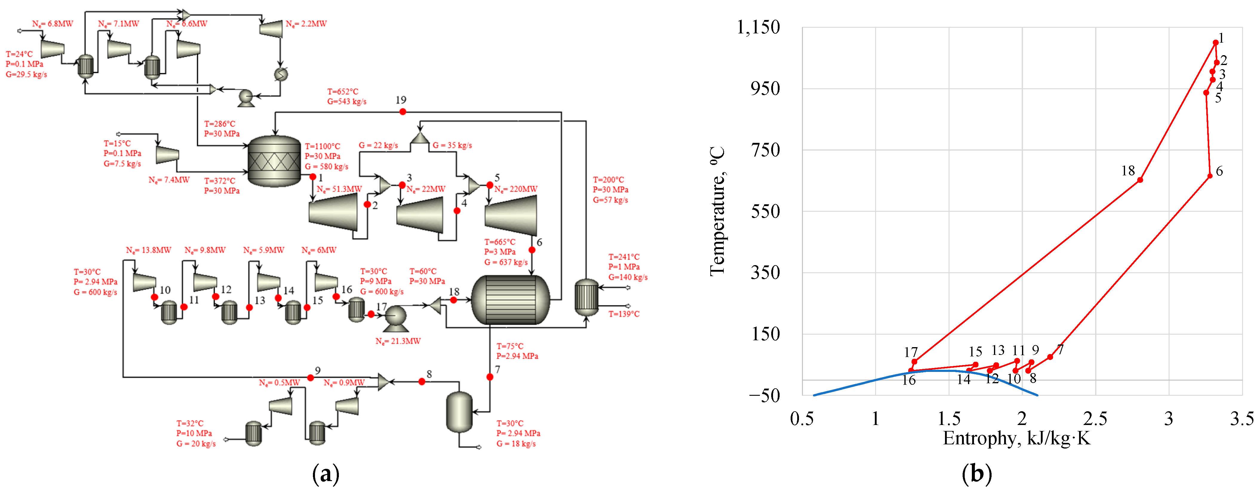
2.1. Heat Balance of the Allam Cycle
2.2. Heat Exchange Equipment
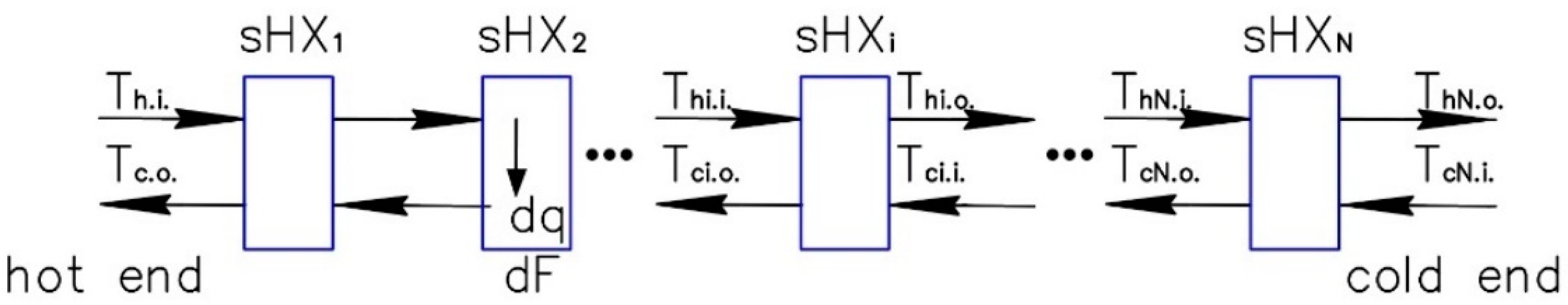
2.3. Methodology of Feasibility Study
- The Allam cycle heat flow analysis, calculation of the basic operation parameters of the regeneration system;
- Structural analysis of the heat exchanging device based on the heat flow analysis of different heat exchanger configurations;
- Analysis of the regenerator underheating and pressure losses influence upon the facility efficiency and the fuel expenses;
- Analysis of the regenerator underheating and acceptable pressure losses influence upon the regenerator dimensions and price;
- Summarizing fuel and regenerator manufacturing expenses, comparison with the basic version, determination of the nest parameters.
- Channel manufacturing by photo-chemical etching has constant price per an area unit;
- The nonproductive expenses, taxes, administrative expenses, etc., are taken into account by a multiplying coefficient k = 1.45;
- The fuel natural gas price is assumed as the mean whole sale Russian power production industry price.
3. Results and Discussion
3.1. The Cycle Thermodynamic Analysis
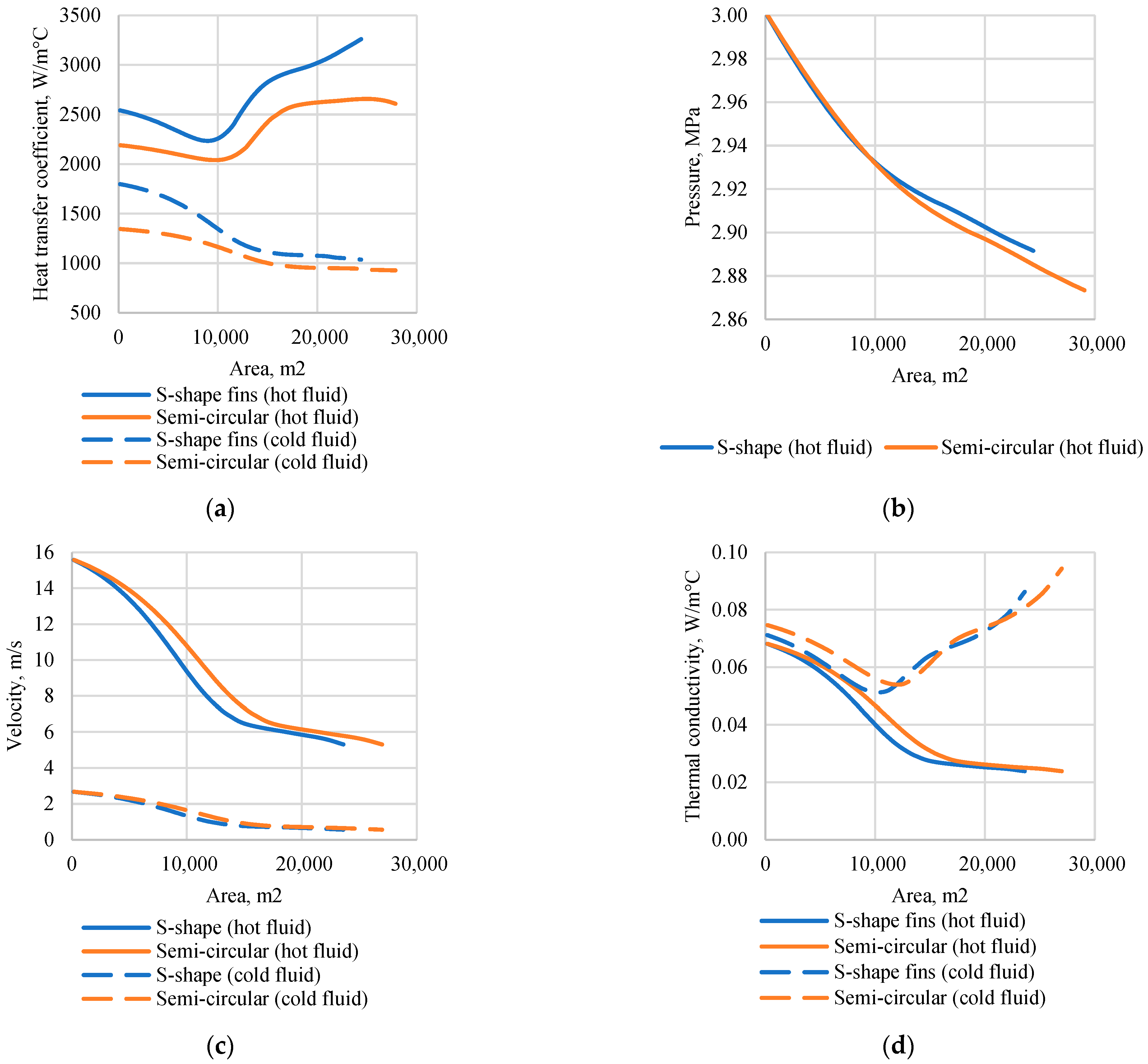
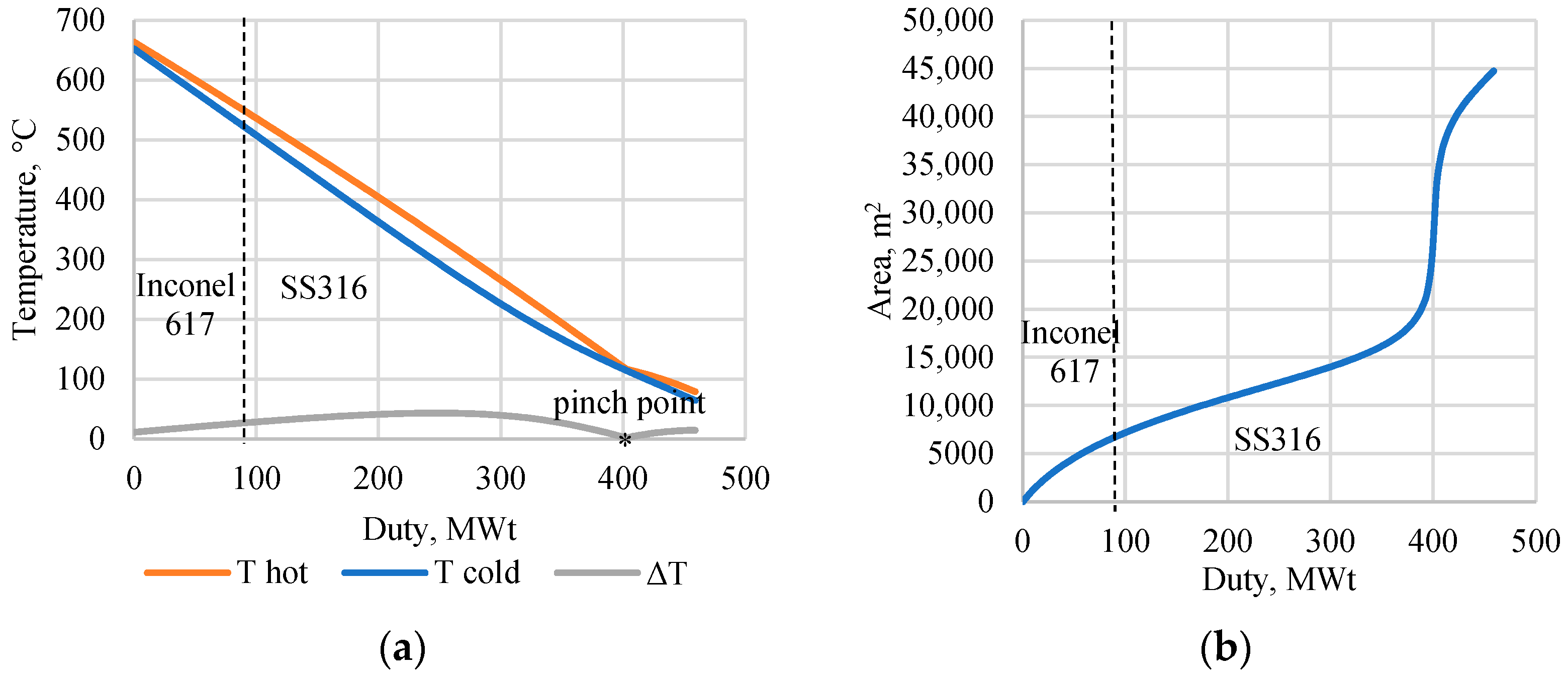
3.2. The Design Parameters of the Regenerator
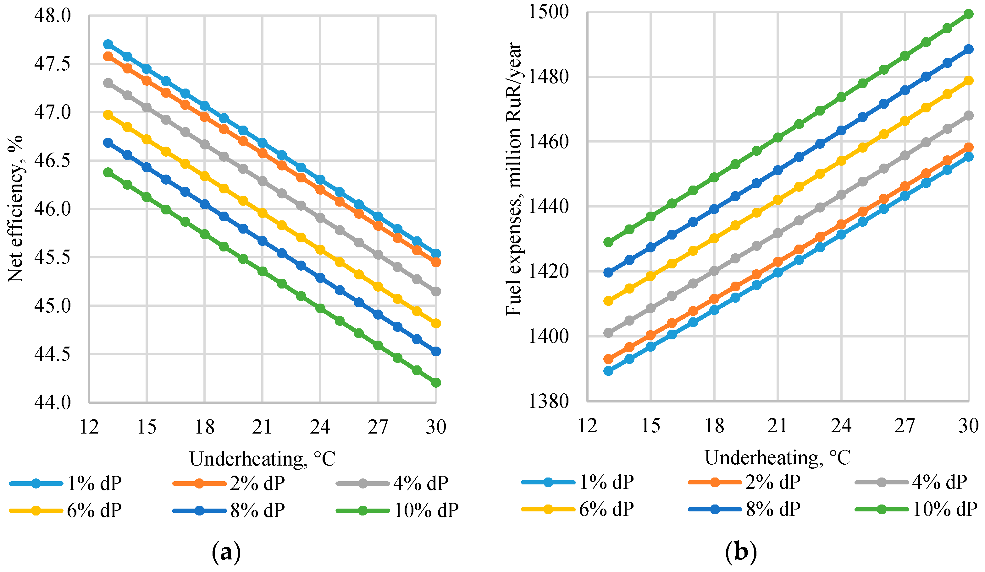
3.3. Change in the Energy Efficiency of the Power Facility
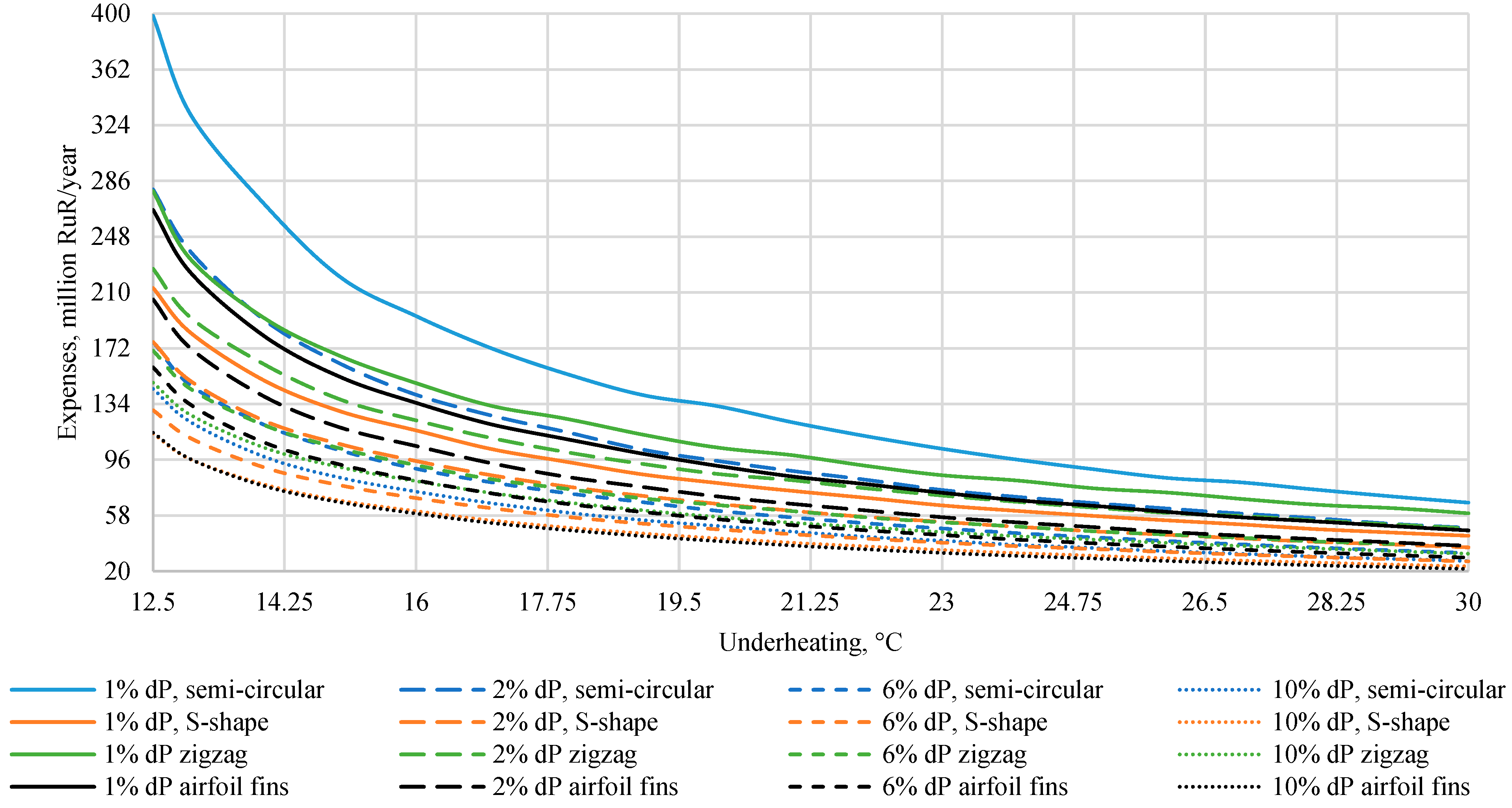
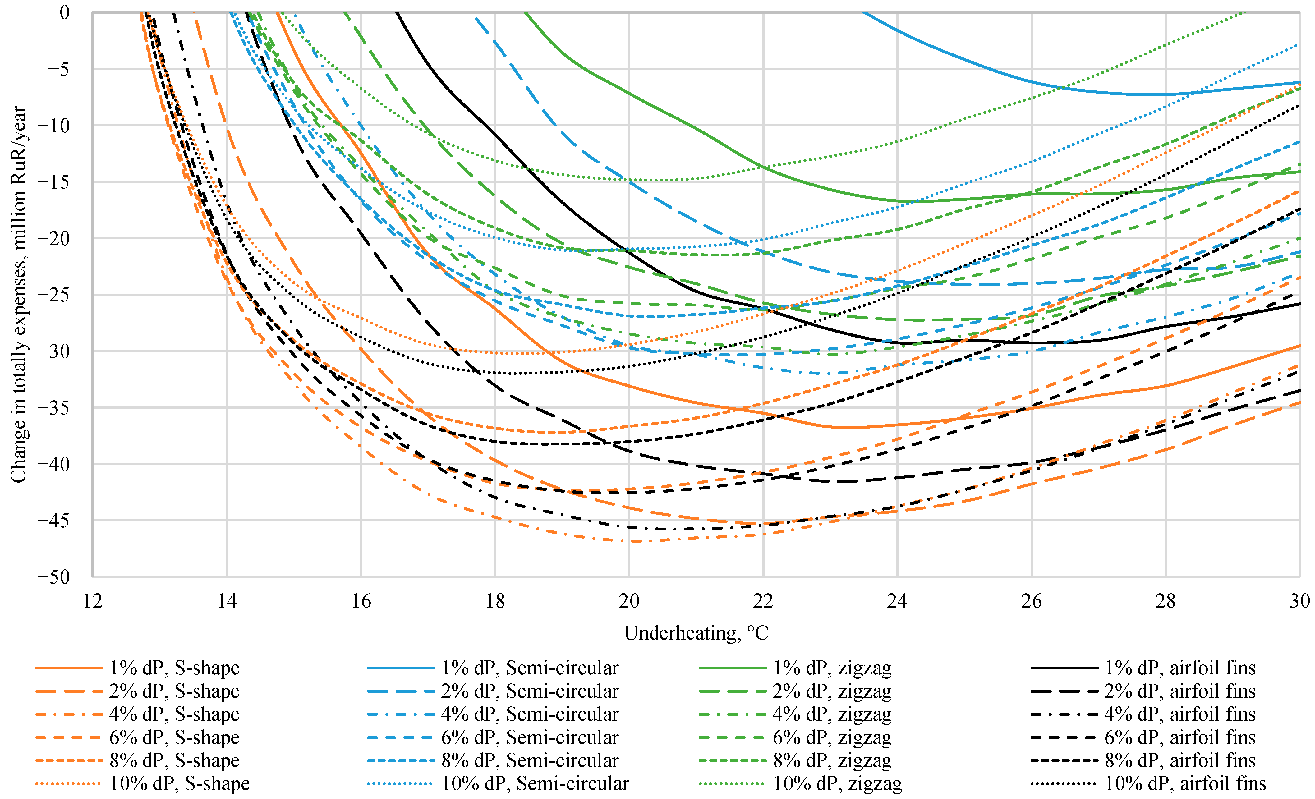
3.4. Optimization of Design Parameters of the Regenerator
4. Conclusions
- Underheating increase in the feed heating system by 1 °C leading to efficiency factor drop of the net Allam cycle by an average of 0.13% and increases fuel costs by 0.28%. Increase of pressure drop in the hot channel by 1% reduces efficiency of electrical power generation by an average of 0.14%.
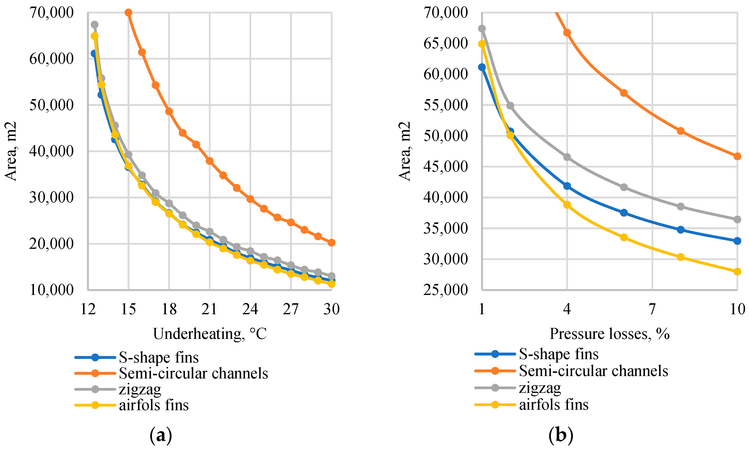
- Increase of underheating in the regenerator from 12.5 °C to 15 °C results in reduction of the required heat exchange area by an average of 42.5%, from 15 °C to 20 °C—by 40%, and from 20 °C to 25 °C—by 30.5%, for the channels of all shapes under review.
- Transition from straight semicircular channels to more complicated shapes is accompanied by a reduction of the required heat exchange area: under pressure drop of 1% and underheating of 15 °C, heat exchange area in the apparatus with zigzag channels is 1.78 times less than in case with straight channels, with airfoil fins—1.89 times, and with S-shaped fins—1.91 times. Meanwhile the most cost-efficient set of geometric parameters of the regenerator is determined by operating parameters of the apparatus.
- The maximum increment of cumulative costs is achieved under underheating and pressure drop equal to 23 °C and 4%—for straight semicircular channels (−32 mln. RuR/year as compared to the base level), 23 °C and 4% – for zigzag channels (−29.8 mln. RuR/year), 20 °C and 4%—for channels with airfoil fins (−45.75 mln. RuR/year), and 21 °C and 4%—for channels with S-shaped fins (−46.83 mln. RuR/year).
Author Contributions
Funding
Data Availability Statement
Conflicts of Interest
References
- Change, Intergovernmental Panel on Climate. Climate change 2007: The physical science basis. Agenda 2007, 6, 333. [Google Scholar]
- Dutka, M.; Ditaranto, M.; Løvås, T. Application of a central composite design for the study of NOx emission performance of a low NOx burner. Energies 2015, 8, 3606–3627. [Google Scholar] [CrossRef] [Green Version]
- Volchyn, I.; Haponych, L. Estimate of the sulfur dioxide concentration at thermal power plants fired by Donetsk coal. Power Technol. Eng. 2014, 48, 218–221. [Google Scholar] [CrossRef]
- Adu, E.; Zhang, Y.; Liu, D.; Tontiwachwuthikul, P. Parametric process design and economic analysis of post-combustion CO2 capture and compression for coal-and natural gas-fired power plants. Energies 2020, 13, 2519. [Google Scholar] [CrossRef]
- Rogalev, A.; Rogalev, N.; Kindra, V.; Komarov, I.; Zlyvko, O. Research and Development of the Oxy-Fuel Combustion Power Cycles with CO2 Recirculation. Energies 2021, 14, 2927. [Google Scholar] [CrossRef]
- IEAGHG. Oxy-Combustion Turbine Power Plants; International Energy Agency Greenhouse Gas: Cheltenham, UK, 2015. [Google Scholar]
- Chen, L.; Yong, S.Z.; Ghoniem, A.F. Oxy-fuel combustion of pulverized coal: Characterization, fundamentals, stabilization and CFD modeling. Prog. Energy Combust. Sci. 2012, 38, 156–214. [Google Scholar] [CrossRef]
- Shaddix, C.R.; Molina, A. Particle imaging of ignition and devolatilization of pulverized coal during oxy-fuel combustion. Proc. Combust. Inst. 2009, 32, 2091–2098. [Google Scholar] [CrossRef]
- Leckner, B.; Gómez-Barea, A. Oxy-fuel combustion in circulating fluidized bed boilers. Appl. Energy 2014, 125, 308–318. [Google Scholar] [CrossRef]
- Czakiert, T.; Bis, Z.; Muskala, W.; Nowak, W. Fuel conversion from oxy-fuel combustion in a circulating fluidized bed. Fuel Processing Technol. 2006, 87, 531–538. [Google Scholar] [CrossRef]
- Allam, R.; Martin, S.; Forrest, B.; Fetvedt, J.; Lu, X.; Freed, D.; Brown Jr, G.W.; Sasaki, T.; Itoh, M.; Manning, J. Demonstration of the Allam Cycle: An update on the development status of a high efficiency supercritical carbon dioxide power process employing full carbon capture. Energy Procedia 2017, 114, 5948–5966. [Google Scholar] [CrossRef]
- Rogalev, A.; Rogalev, N.; Kindra, V.; Zlyvko, O.; Vegera, A. A Study of Low-Potential Heat Utilization Methods for Oxy-Fuel Combustion Power Cycles. Energies 2021, 14, 3364. [Google Scholar] [CrossRef]
- Penkuhn, M.; Tsatsaronis, G. Exergy analysis of the Allam cycle. In Proceedings of the 5th international symposium–supercritical CO2 power cycles, San Antonio, TX, USA, 8–31 March 2016; pp. 6–7. [Google Scholar]
- Chaturvedi, R.; Kennedy, E.; Metew, S. CO2 Sequestration by Allam Cycle. 2021. Available online: https://repository.upenn.edu/cbe_sdr/135/ (accessed on 1 July 2022).
- Kindra, V.; Rogalev, A.; Lisin, E.; Osipov, S.; Zlyvko, O. Techno-economic analysis of the oxy-fuel combustion power cycles with near-zero emissions. Energies 2021, 14, 5358. [Google Scholar] [CrossRef]
- Hesselgreaves, J.E.; Law, R.; Reay, D. Compact Heat Exchangers: Selection, Design and Operation; Butterworth-Heinemann: Oxford, UK, 2016. [Google Scholar]
- Diffusion Bonded Heat Exchangers and Support|Heatric. Available online: https://www.heatric.com (accessed on 27 May 2022).
- Aneesh, A.; Sharma, A.; Srivastava, A.; Chaudhury, P. Effects of wavy channel configurations on thermal-hydraulic characteristics of Printed Circuit Heat Exchanger (PCHE). Int. J. Heat Mass Transf. 2018, 118, 304–315. [Google Scholar] [CrossRef]
- Lee, S.-M.; Kim, K.-Y. Comparative study on performance of a zigzag printed circuit heat exchanger with various channel shapes and configurations. Heat Mass Transf. 2013, 49, 1021–1028. [Google Scholar] [CrossRef]
- Chen, F.; Zhang, L.; Huai, X.; Li, J.; Zhang, H.; Liu, Z. Comprehensive performance comparison of airfoil fin PCHEs with NACA 00XX series airfoil. Nucl. Eng. Des. 2017, 315, 42–50. [Google Scholar] [CrossRef]
- Xu, X.; Ma, T.; Li, L.; Zeng, M.; Chen, Y.; Huang, Y.; Wang, Q. Optimization of fin arrangement and channel configuration in an airfoil fin PCHE for supercritical CO2 cycle. Appl. Therm. Eng. 2014, 70, 867–875. [Google Scholar] [CrossRef]
- Kwon, J.G.; Kim, T.H.; Park, H.S.; Cha, J.E.; Kim, M.H. Optimization of airfoil-type PCHE for the recuperator of small scale brayton cycle by cost-based objective function. Nucl. Eng. Des. 2016, 298, 192–200. [Google Scholar] [CrossRef]
- Ngo, T.L.; Kato, Y.; Nikitin, K.; Tsuzuki, N. New printed circuit heat exchanger with S-shaped fins for hot water supplier. Exp. Therm. Fluid Sci. 2006, 30, 811–819. [Google Scholar] [CrossRef]
- Ngo, T.L.; Kato, Y.; Nikitin, K.; Ishizuka, T. Heat transfer and pressure drop correlations of microchannel heat exchangers with S-shaped and zigzag fins for carbon dioxide cycles. Exp. Therm. Fluid Sci. 2007, 32, 560–570. [Google Scholar] [CrossRef]
- Nikitin, K.; Kato, Y.; Ishizuka, T. Experimental thermal-hydraulics comparison of microchannel heat exchangers with zigzag channels and S-shaped fins for gas turbine reactors. In Proceedings of the of Fifteenth International Conference on Nuclear Engineering, Nagoya, Japan, 22–26 April 2007; pp. 22–26. [Google Scholar]
- Rogalev, A.; Kindra, V.; Komarov, I.; Osipov, S.; Zlyvko, O. Structural and Parametric Optimization of S-CO2 Thermal Power Plants with a Pulverized Coal-Fired Boiler Operating in Russia. Energies 2021, 14, 7136. [Google Scholar] [CrossRef]
- Sridharan, M. Applications of artificial intelligence techniques in heat exchanger systems. In Advanced Analytic and Control Techniques for Thermal Systems with Heat Exchangers; Elsevier: Amsterdam, The Netherlands, 2020; pp. 325–334. [Google Scholar]
- Sridharan, M. Application of fuzzy logic expert system in predicting cold and hot fluid outlet temperature of counter-flow double-pipe heat exchanger. In Advanced Analytic and Control Techniques for Thermal Systems with Heat Exchangers; Elsevier: Amsterdam, The Netherlands, 2020; pp. 307–323. [Google Scholar]
- Krzywanski, J. A general approach in optimization of heat exchangers by bio-inspired artificial intelligence methods. Energies 2019, 12, 4441. [Google Scholar] [CrossRef] [Green Version]
- Xie, G.; Sundén, B.; Wang, Q. Optimization of compact heat exchangers by a genetic algorithm. Appl. Therm. Eng. 2008, 28, 895–906. [Google Scholar] [CrossRef]
- Krzywanski, J. Heat transfer performance in a superheater of an industrial CFBC using fuzzy logic-based methods. Entropy 2019, 21, 919. [Google Scholar] [CrossRef] [Green Version]
- Krasnoshchekov, E.; Kuraeva, I.; Protopopov, V. Local heat transfer of carbon dioxide at supercritical pressure under cooling conditions. High Temp. 1969, 7, 856. [Google Scholar]
- Lu, M.; Yan, X.; Wang, J.; Sun, Y.; Gong, Z. Thermal hydraulic performance analysis of PCHE precooler for supercritical CO2 Brayton cycle. In Proceedings of the 2019 5th International Conference on Transportation Information and Safety (ICTIS), Liverpool, UK, 14–17 July 2019; pp. 537–541. [Google Scholar]
- Çengel, Y.A. Heat and Mass Transfer: A Practical Approach; McGraw-Hill: New York, NY, USA, 2007. [Google Scholar]
- Hosseini, H.S.; Shamanian, M.; Kermanpur, A. Characterization of microstructures and mechanical properties of Inconel 617/310 stainless steel dissimilar welds. Mater. Charact. 2011, 62, 425–431. [Google Scholar] [CrossRef]
- Rogalev, N.; Kindra, V.; Komarov, I.; Osipov, S.; Zlyvko, O.; Lvov, D. Comparative Analysis of Low-Grade Heat Utilization Methods for Thermal Power Plants with Back-Pressure Steam Turbines. Energies 2021, 14, 8519. [Google Scholar] [CrossRef]
- Caputo, A.C.; Pelagagge, P.M.; Salini, P. Heat exchanger design based on economic optimisation. Appl. Therm. Eng. 2008, 28, 1151–1159. [Google Scholar] [CrossRef]
- Scaccabarozzi, R.; Gatti, M.; Martelli, E. Thermodynamic analysis and numerical optimization of the NET Power oxy-combustion cycle. Appl. Energy 2016, 178, 505–526. [Google Scholar] [CrossRef]


| Parameter | Value |
|---|---|
| CO2 turbine inlet temperature, °C | 1100 |
| CO2 turbine inlet pressure, MPa | 30 |
| CO2 turbine outlet pressure, MPa | 3 |
| CO2 turbine coolant temperature, °C | 200 |
| Multi-stage intercooled compressor massflow, kg/s | 600 |
| Isentropic efficiency of turbines and compressors, % | 90 |
| Pumps isentropic efficiency, % | 75 |
| Mechanical efficiency of turbines, compressors, pumps, power generator % | 99 |
| Power generator and electric motor efficiency, % | 99 |
| Cooler-separator exit working fluid temperature, °C | 55 |
| Minimum working fluid temperature, °C | 30 |
| ASU power, MW | 31 |
| Parameter | Value |
|---|---|
| Plate thickness, mm | 1.5 |
| Plate width, mm | 600 |
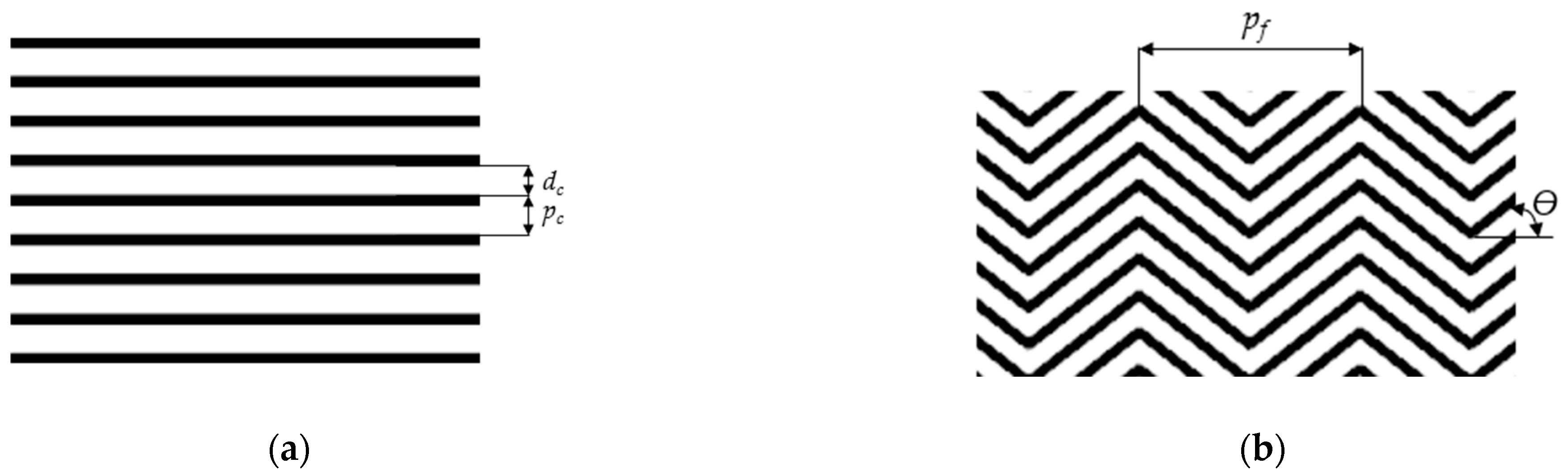
| Semi-circular | |
| Channel pitch pc, mm | 2.4 |
| Channel diameter dc, mm | 2 |
| Zigzag channel | |
| Channel angle ϴ, ° | 52 |
| Channel pitch, mm | 2.4 |
| Channel diameter, mm | 2 |
| Channel step, mm | 7.565 |
| Airfoil fins | |
| Fin depth, mm | 0.94 |
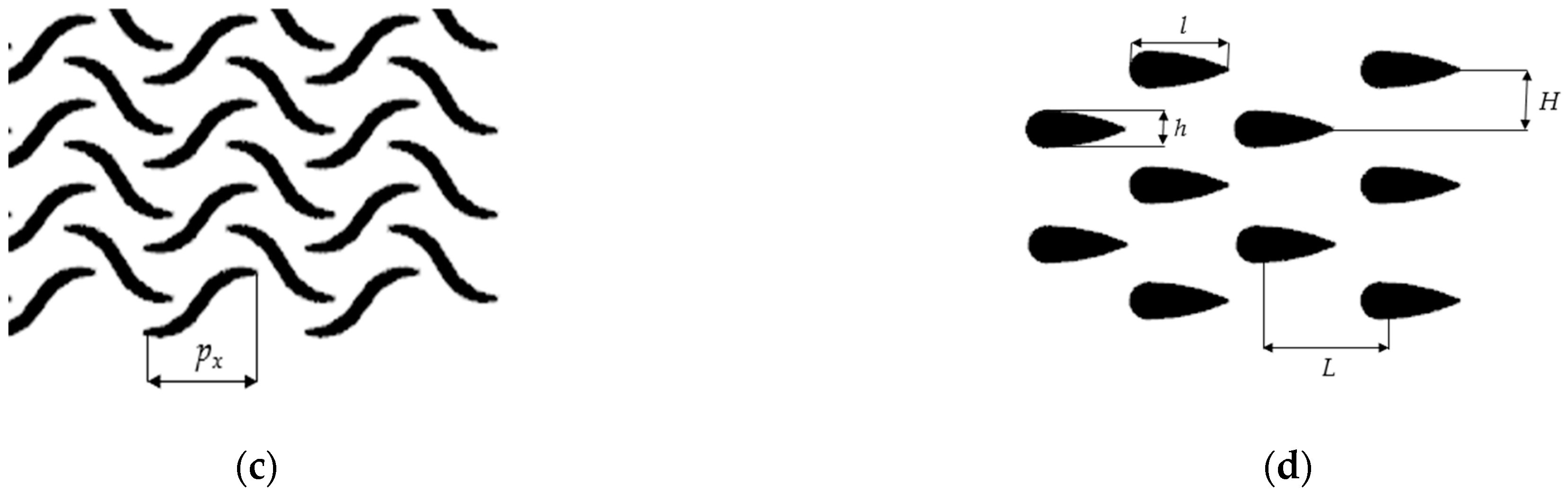
| Pin pitch on the x-axis L, mm | 8 |
| Pin pitch on the y-axis H, mm | 2.2 |
| Fin length l, mm | 4 |
| Fin width h, mm | 0.8 |
| Fin profile | NACA0020 |
| S-shape | |
| Fin pitch px, mm | 7.565 |
| Fin depth, mm | 0.94 |
| Hydraulic diameter, mm | 1.09 |
| Parameters | Hot Channel | Cold Channel |
|---|---|---|
| CO2 temperature at the unit inlet, °C | 665 | 60 |
| CO2 temperature at the unit exit, °C (varies) | 75 | 652 |
| Fluid massflow, kg/s | 637 | 543 |
| Fluid pressure, MPa | 3 | 30 |
| Molar moisture content in the CO2 flow, % | 6.9 | 0.6 |
| Heat power, MW (varies) | 462 | |
| Parameter | Value |
|---|---|
| Fuel price, RuR/m3 | 5.67 |
| Block annual operation, hr | 6000 |
| Low heating value, MJ/m3 | 35.59 |
| Regenerator estimated life, years | 20 |
| Plate photo-chemical etching, RuR/m2 (1$ = 70 RuR) | 11,900 |
| Inconel 617 price, RuR/kg | 10,500 |
| SS316 price, RuR/kg | 1400 |
Publisher’s Note: MDPI stays neutral with regard to jurisdictional claims in published maps and institutional affiliations. |
© 2022 by the authors. Licensee MDPI, Basel, Switzerland. This article is an open access article distributed under the terms and conditions of the Creative Commons Attribution (CC BY) license (https://creativecommons.org/licenses/by/4.0/).
Share and Cite
Kindra, V.; Komarov, I.; Osipov, S.; Zlyvko, O.; Maksimov, I. Feasibility Study of the CO2 Regenerator Parameters for Oxy-Fuel Combustion Power Cycle. Inventions 2022, 7, 66. https://doi.org/10.3390/inventions7030066
Kindra V, Komarov I, Osipov S, Zlyvko O, Maksimov I. Feasibility Study of the CO2 Regenerator Parameters for Oxy-Fuel Combustion Power Cycle. Inventions. 2022; 7(3):66. https://doi.org/10.3390/inventions7030066
Chicago/Turabian StyleKindra, Vladimir, Ivan Komarov, Sergey Osipov, Olga Zlyvko, and Igor Maksimov. 2022. "Feasibility Study of the CO2 Regenerator Parameters for Oxy-Fuel Combustion Power Cycle" Inventions 7, no. 3: 66. https://doi.org/10.3390/inventions7030066
APA StyleKindra, V., Komarov, I., Osipov, S., Zlyvko, O., & Maksimov, I. (2022). Feasibility Study of the CO2 Regenerator Parameters for Oxy-Fuel Combustion Power Cycle. Inventions, 7(3), 66. https://doi.org/10.3390/inventions7030066