2.1. Research Object
Mathematical modeling, which is used as a research method, makes it possible to predict the composition and properties of the produced syngas; therefore, thermodynamic and chemical processes should be competently considered in the developed models [
25], based on the method proposed by S.K. Popov to model a solid fuel gasification process [
26].
The mathematical model of solid fuel gasification is based on a thermodynamic equilibrium approach that is determined by the equilibrium of the chemical reactions of the water–gas shift reaction and the steam reforming of methane (1,2):
The modeling of thermal performance of the gasifier was based on the following conditions and assumptions:
(1) The gasifier is operated continuously and is in the steady thermal state;
(2) Constant pressure is maintained in the gasifier;
(3) Oxygen-enriched air and water steam act as an oxidizer;
(4) Hydrogen, nitrogen, and oxygen are fully involved in the syngas generation; that is, their entire masses react in the process of the gasification reaction;
(5) Ash and syngas leave the gasifier as a single stream, having the same temperature;
(6) Syngas consists of carbon dioxide, carbon monoxide, water, hydrogen, nitrogen, and methane (the syngas components are in a state of thermodynamic equilibrium when they leave the gasifier).
The modeling algorithm is as follows.
(1) Set initial data to be used for calculations, i.e., as-received fuel percentage composition and the parameters of the oxidizer components—temperatures and relative mass flow rates of oxygen and steam, physical properties of fuel moisture, heat, and percentage of external heat losses.
(2) Define auxiliary functions, i.e., temperature functions for specific heat; temperature dependences between equilibrium constants of reactions of dissociation into atoms of H2O, CO, CO2, and H2 molecules (necessary to find the equilibrium constant of the reaction of water–gas) for the water–gas reactions and for the steam–methane reforming reactions; temperature functions for the specific heat of combustible gases, the specific heat of the oxidizer, and the specific heat of the syngas.
(3) Calculate specific volumes of chemical elements in fuel, theoretical flow rate of oxygen from a mixture of nitrogen and oxygen, oxidizer flow rate coefficient—ratio of oxygen mass flow to purity, actual oxidizer flow rate, and specific volumes of chemical elements in the oxidizer, according to the expressions [
17,
19]:
Specific volumes of chemical elements are measured using the formula below (8).
where V
m stands for molar volume of gases under normal conditions, l;
Mel stands for molar mass of a chemical element, g/mol;
n stands for the number of atoms of a chemical element in the feedstock;
Vel stands for content of a chemical element in the feedstock by volume, %.
(4) Solve the equation system that links specific volumes of the source chemical elements and specific yield of the resulting syngas.
(5) Perform thermal design of the reactor (9) and specify the syngas temperature.
where
stands for calorific value of the fuel, kJ/(kg of fuel);
stands for sensible heat of the fuel, kJ/(kg of fuel);
Qox stands for sensible heat of the oxidizer, kJ/(kg of fuel);
stands for calorific value of the syngas, kJ/(kg of fuel);
stands for sensible heat of the syngas, kJ/(kg of fuel);
Qevp stands for heat consumed for evaporation of moisture contained in the fuel, kJ/(kg of fuel);
Qenv stands for external heat losses through the gasifier wall, kJ/(kg of fuel); and
Qash stands for sensible heat of ash, kJ/(kg of fuel).
(6) After all necessary values are determined, the initial values of the syngas temperature and its components production are assumed. The solving equations system includes the chemical elements mass balance equations and the active masses law equations for the humid gas reaction (5) and steam conversion (6).
where
Pg—gasifier pressure, bar;
Kp1,
Kp2—equilibrium constants for the reactions of water–gas and methane steam conversion that are found from the atomization coefficients.
(7) The final results of the calculations are as follows: specific yield of the syngas components, percentage composition of the syngas, temperature of the syngas, specific yield of hydrogen, hydrogen production efficiency, calorific value of the syngas, the structure of the heat balance (the distribution of the heat energy supplied to a thermomechanical system among the various drains upon it, including both useful output and losses) of the gasification reactor, chemical efficiency of gasification (7), and the thermal efficiency of gasification (8).
The developed model helps calculate specific volumes of the chemical elements within the syngas, its temperature, and calorific value. Coal properties (
Table 2) and operation parameters of the gasifier (
Table 3) are set as initial data [
2].
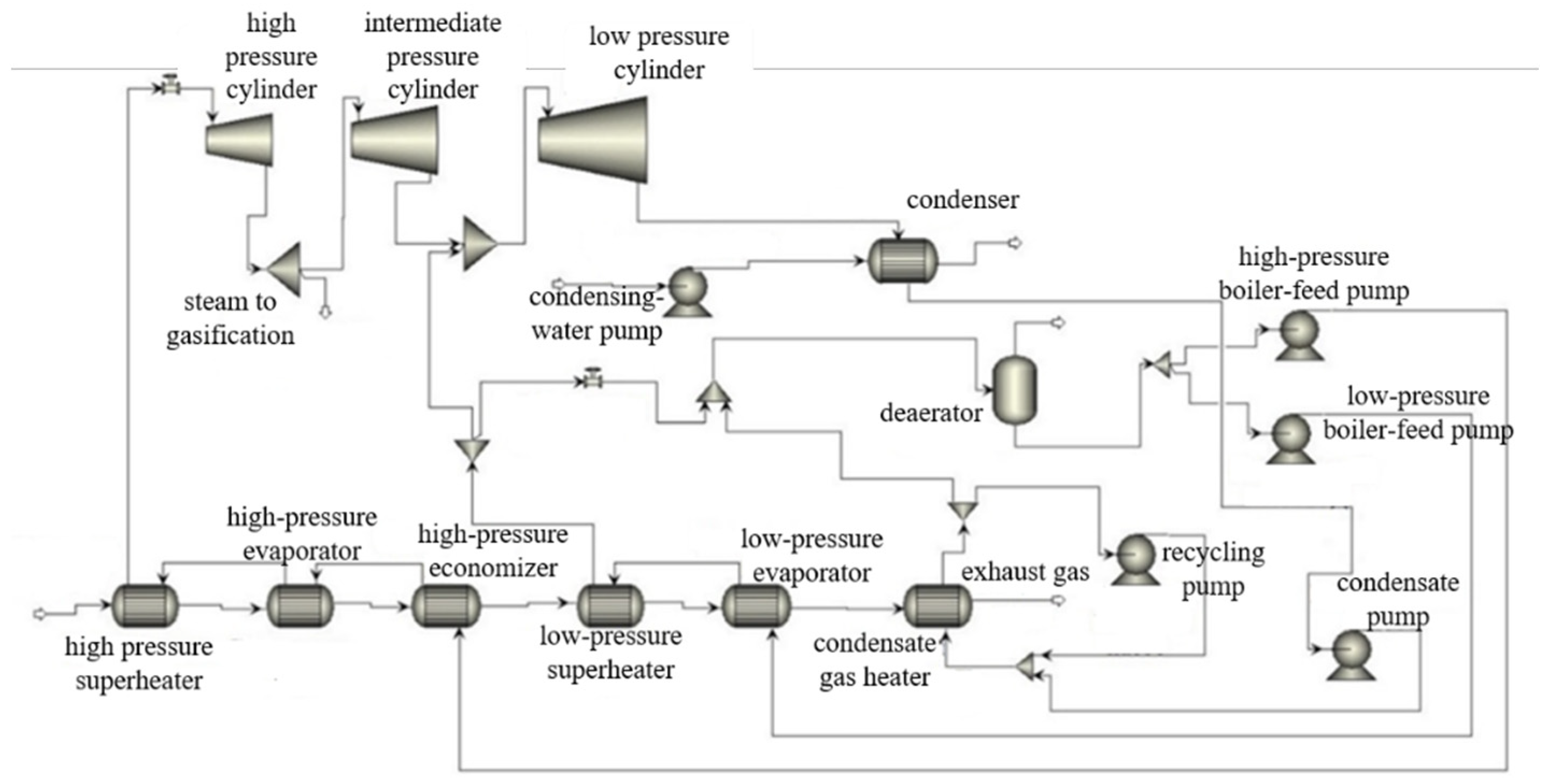
Figure 1 shows a heat flow scheme of the investigated CC with fuel gasification.
The thermal efficiency evaluation algorithm is a combination of widely known CC heat flow analysis methods, including the model built using Aspen Plus computer code. The only exclusion is the analysis of syngas parameters at the gasifier exit, which follows the above-described method. The heat flow analysis input data are summarized in
Table 4.
2.2. Methods
To understand the correct functioning of the developed model, the calculation results were verified with the results of the research in [
27]. The results are presented in
Table 5.
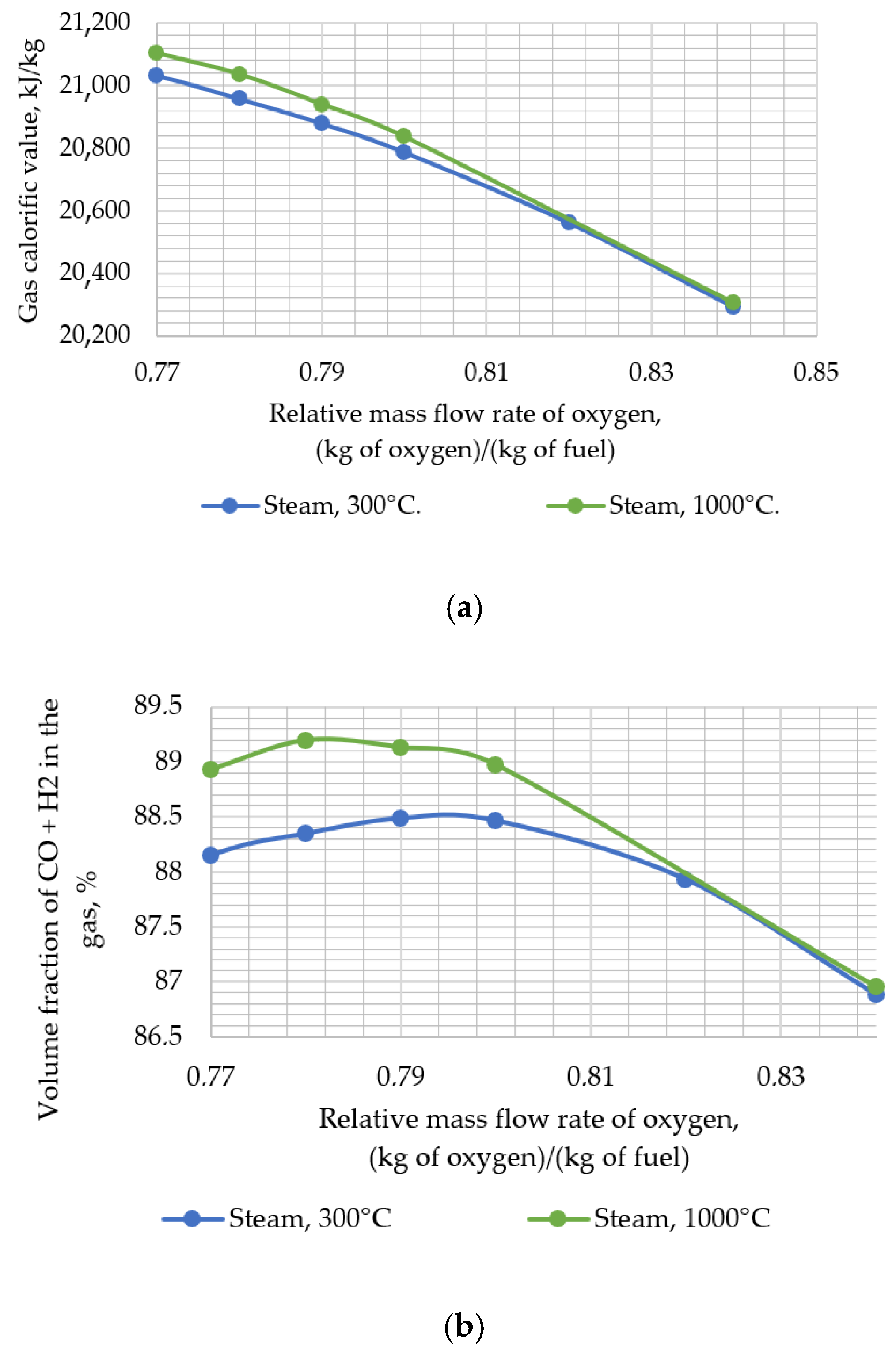
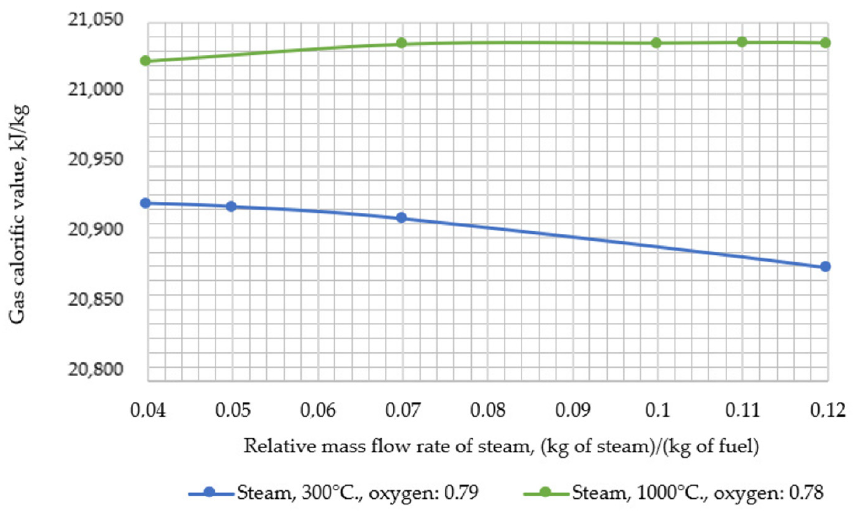
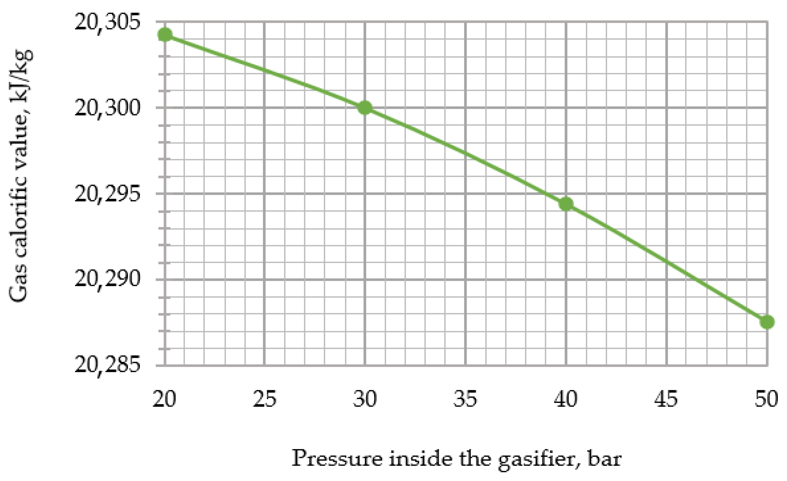
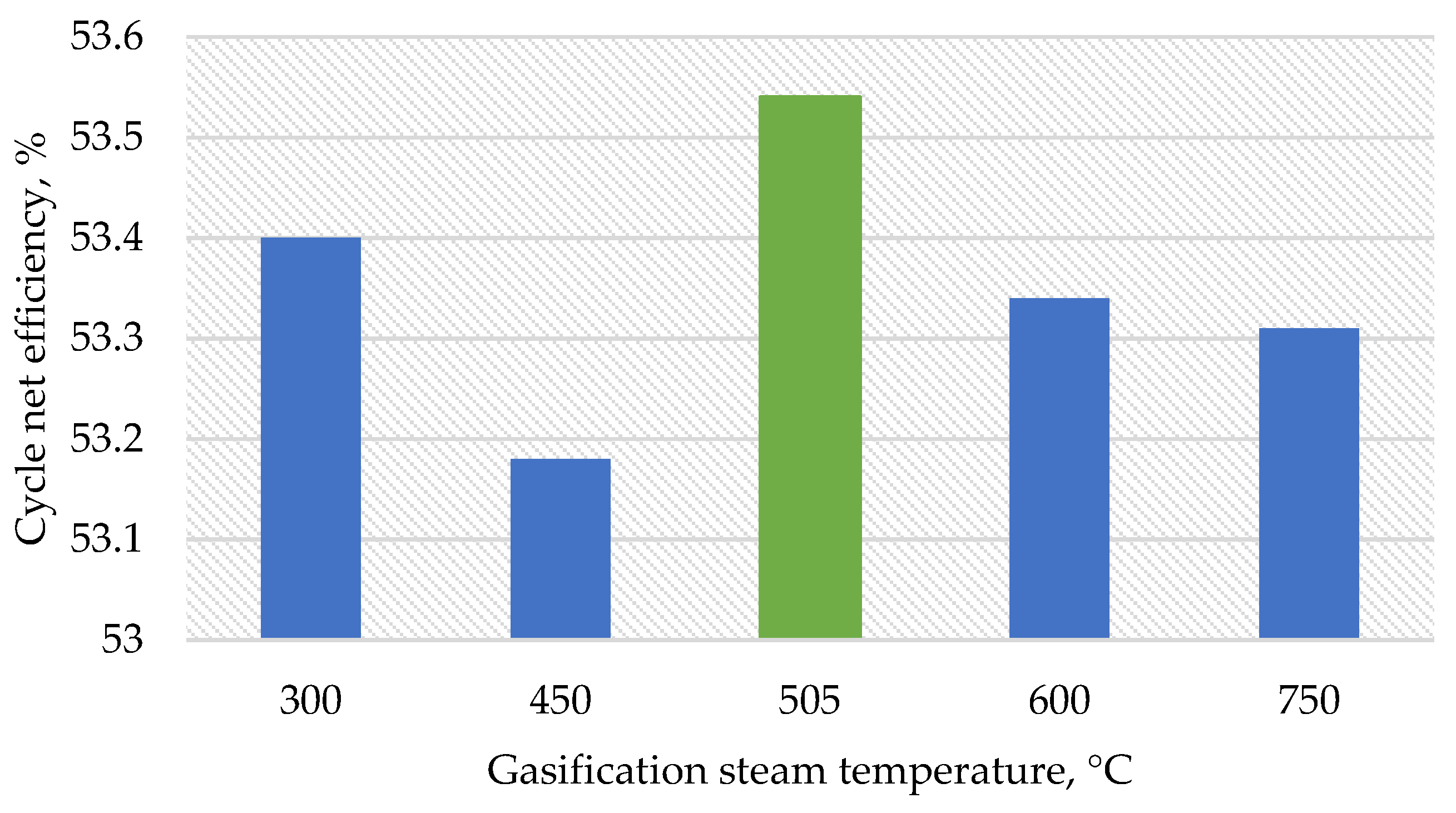
Thereafter, the developed model was used to assess the impact of changing the input parameters of the gasifier (i.e., temperature and relative mass flow rate of steam, temperature, and relative mass flow rate of oxygen and pressure) on the resulting output parameters (i.e., calorific value and temperature of the syngas). During the research, the following temperature values of steam supplied for gasification were assumed: 300, 450, 600, 750, 900, and 1000 °C.
Heat flow analysis of the CC with gasification included calculation of the syngas contents, LHV, and temperature using the above presented method. In general, the analysis includes computer simulation models of the cooled gas turbine, twin-flow heat recovery boiler, and steam turbine built using Aspen Plus software [
28]. The working fluid thermophysical parameters were determined with high accuracy using the NIST Reference Fluid Thermodynamic and Transport Properties Database (REFPROP) [
29].
The influence of the gasification technology on the cycle efficiency was evaluated for different stations of the steam bleeding into the gasifier steam turbine and the regenerative heat exchanger that uses the gasifier exit syngas heat. The calculation of thermal CCGTs with gasification is made using a set of developed mathematical models of power plants, including the model of an air separation plant, a gas generator model built using the MS Excel software package, and a CCGT model created using the Aspen Plus software package.
Figure 2 presents a CC with a gasification heat flow scheme simulated with Aspen Plus code. The facility includes a cooled gas turbine and a steam power facility with steam bleeding.
The cycle version without the steam bleeding from the steam turbine contains the steam production in a surface heat exchanger using the syngas heat. The surface heat exchanger is a new additional element (
Figure 3). This study included the changes in the gasification steam flow and temperature that influence the heat exchanger exit temperature and the heat exchanger water flow.
The cycle computer simulation preceded the calculations of the main power production performance, as follows:
where
NASP—ASU power consumption, MW;
Ncomp O2—mechanical power of the ASU exit oxygen compressor that supplies compressed oxygen to the gasifier, MW;
NKP—condensate pump mechanical power, MW;
NCCP—condensate circulation pump mechanical power, MW;
NHPPP—high pressure circuit feeding pump power, MW;
NLPPP—low pressure circuit feeding pump power, MW;
NCRPP—condensate recirculation pump power, MW; η
te heat transportation efficiency, %; η
em—electric motor efficiency, %.
where
NGT—gas turbine mechanical power production, MW;
NST—steam turbine mechanical power production, MW; and
NAC—air compressor mechanical power consumption, MW; (the compressor is mounted on the gas turbine shaft. In the case of air combustion, it compresses the working fluid. In the case of oxygen combustion, it compresses the GT cooling air.); η
ep—lectric power generator efficiency, %.
where
Nnet power—cycle net power calculated by the equation (2.46), MW;
B—coal fuel consumption, kg/s; and
Q—coal fuel LHV, MJ/kg.

