
Numerical Study on Plastic Strain Distributions and Mechanical Behaviour of a Tube under Bending

 ,
, 
 ,
, 

Abstract
:1. Introduction
2. Numerical Model
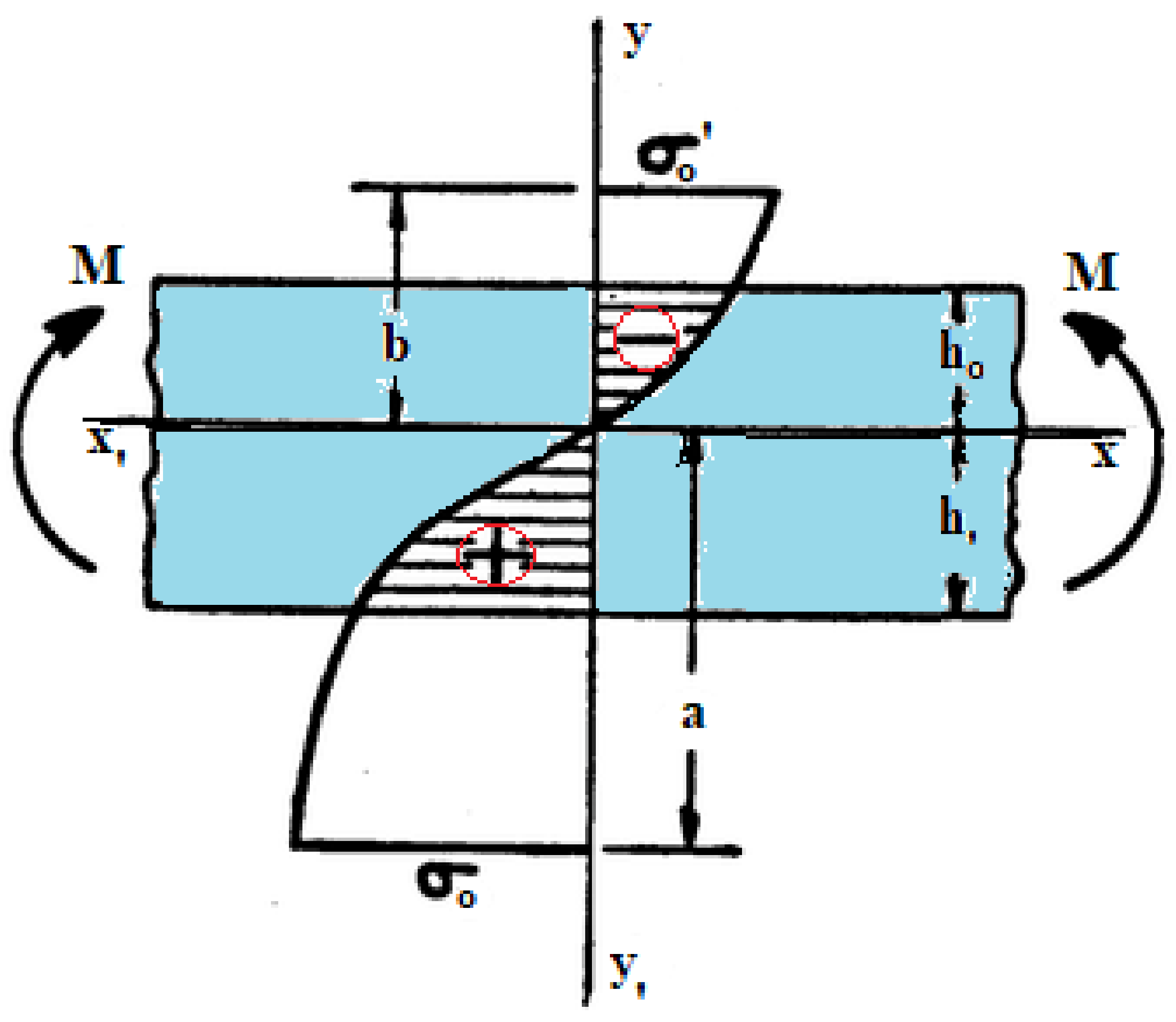
2.1. Tubular Bending
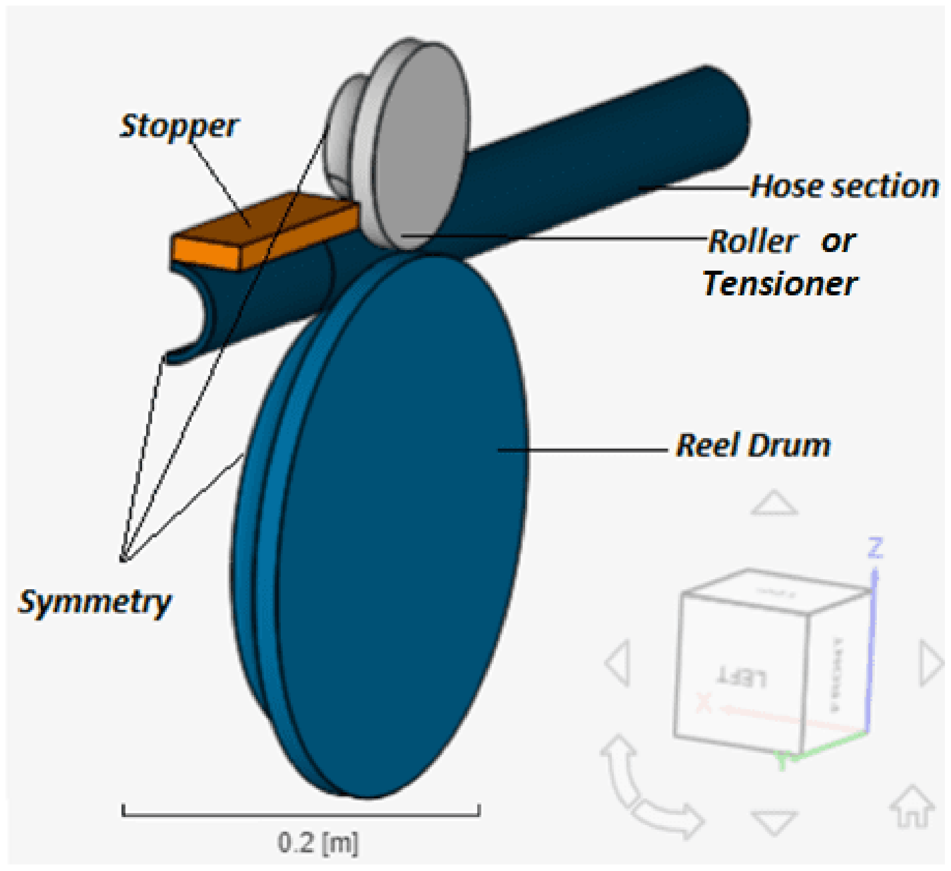
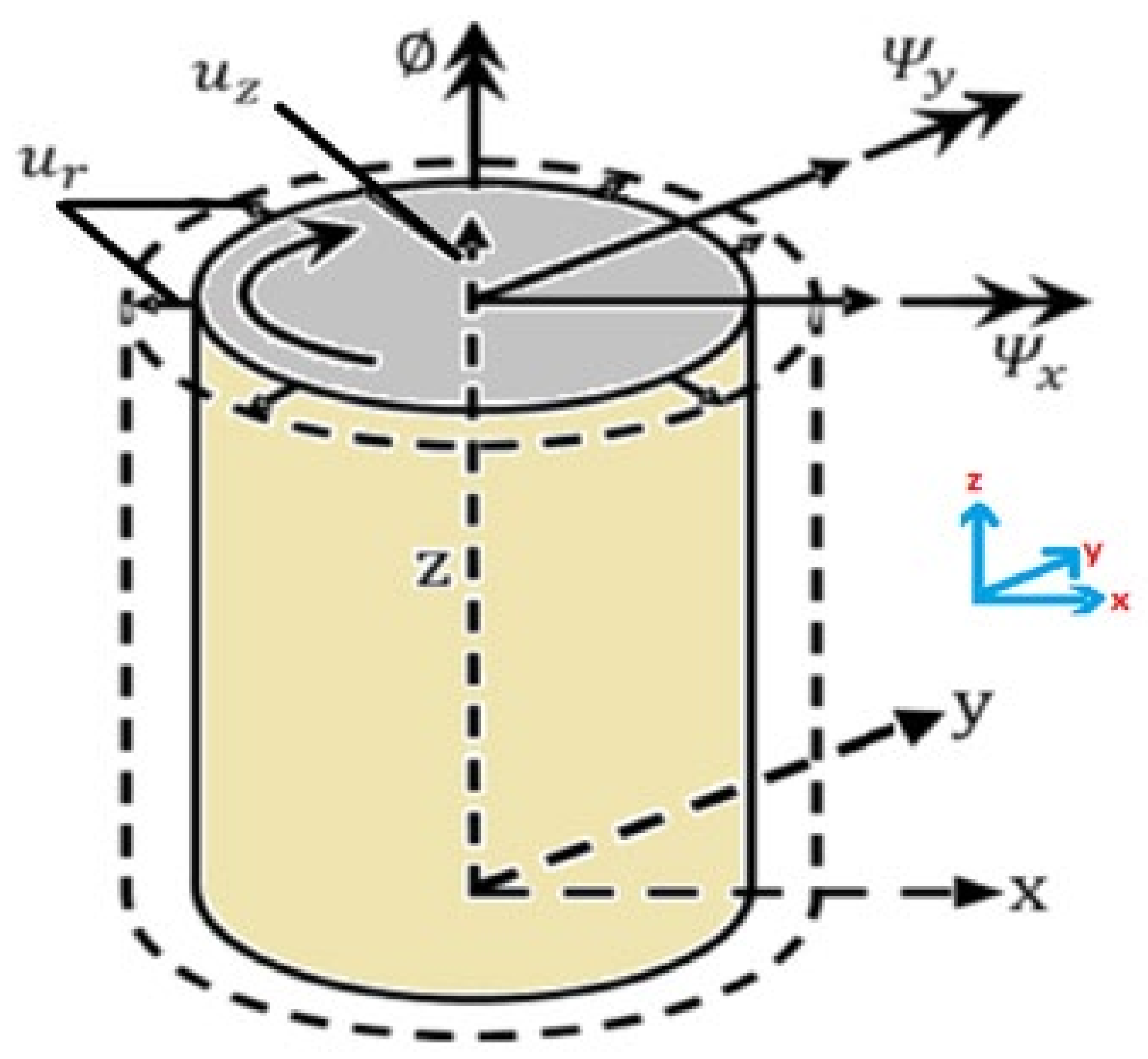
2.2. Model Description
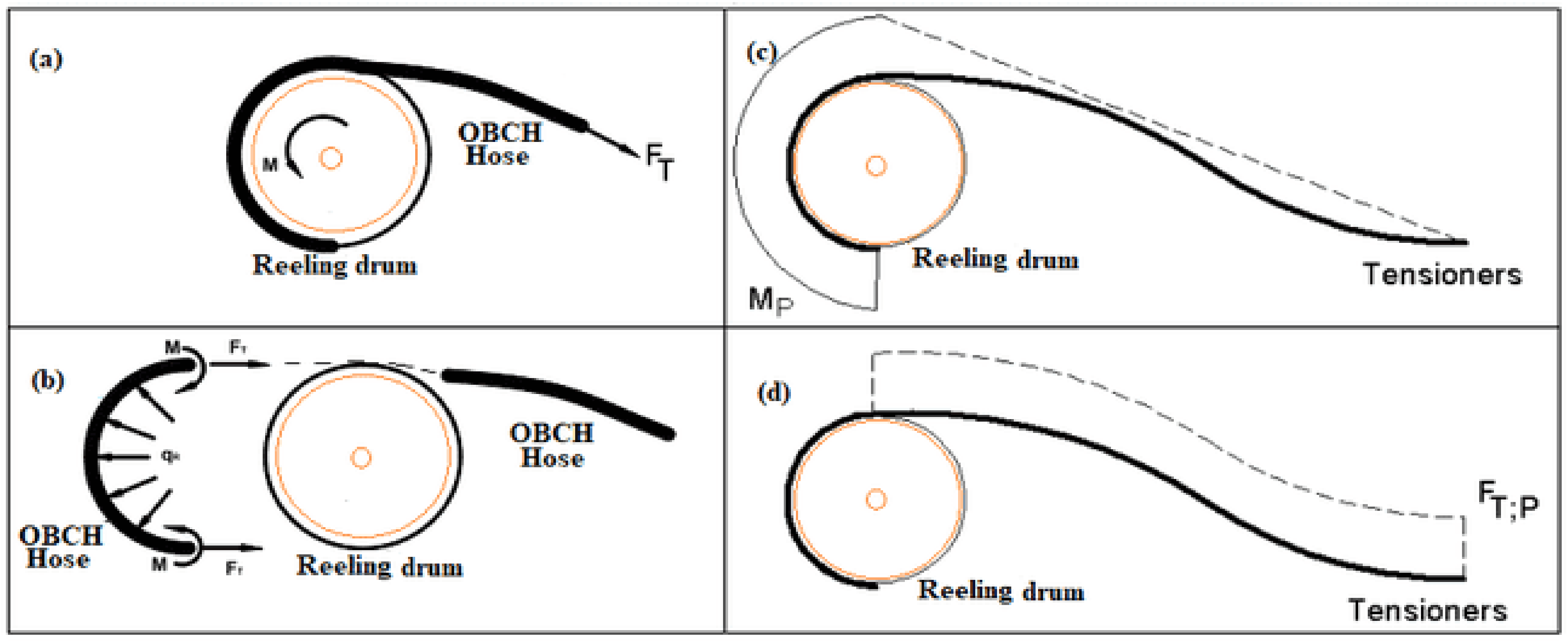
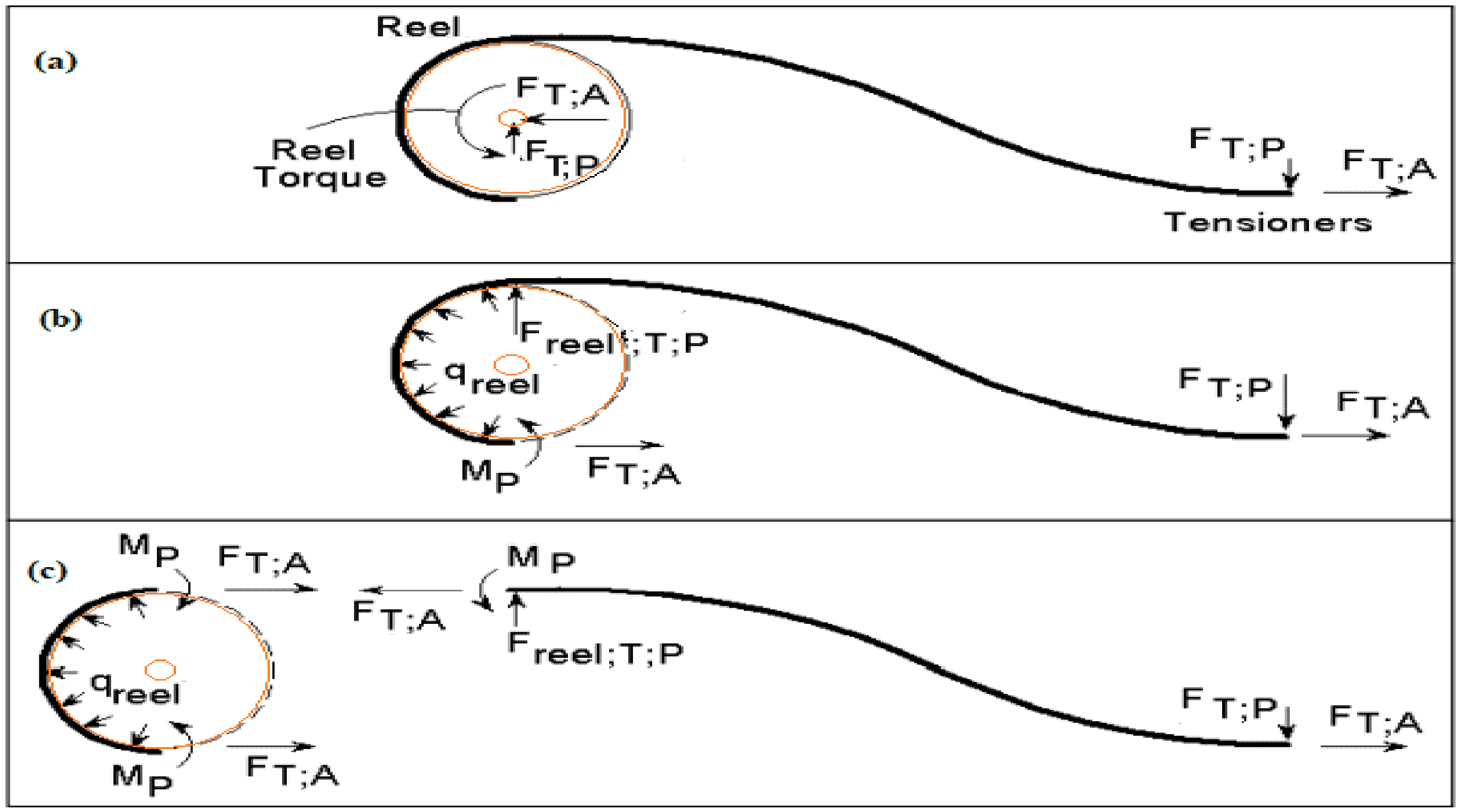
2.3. Bending and Reeling Model
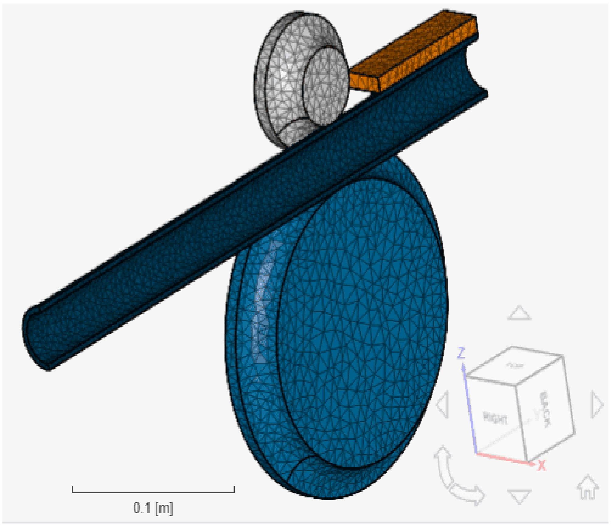
2.4. Finite Element Model (FEM)
2.5. Contact Details
3. Materials and Methodology
3.1. Material Properties
3.2. Elasto-Plasticity of Hose
3.3. Design Load Conditions
3.4. Boundary Conditions
3.5. Mesh Details
4. Results and Discussion
4.1. Results on Total Strain and Effective Plastic Strain (EPS)
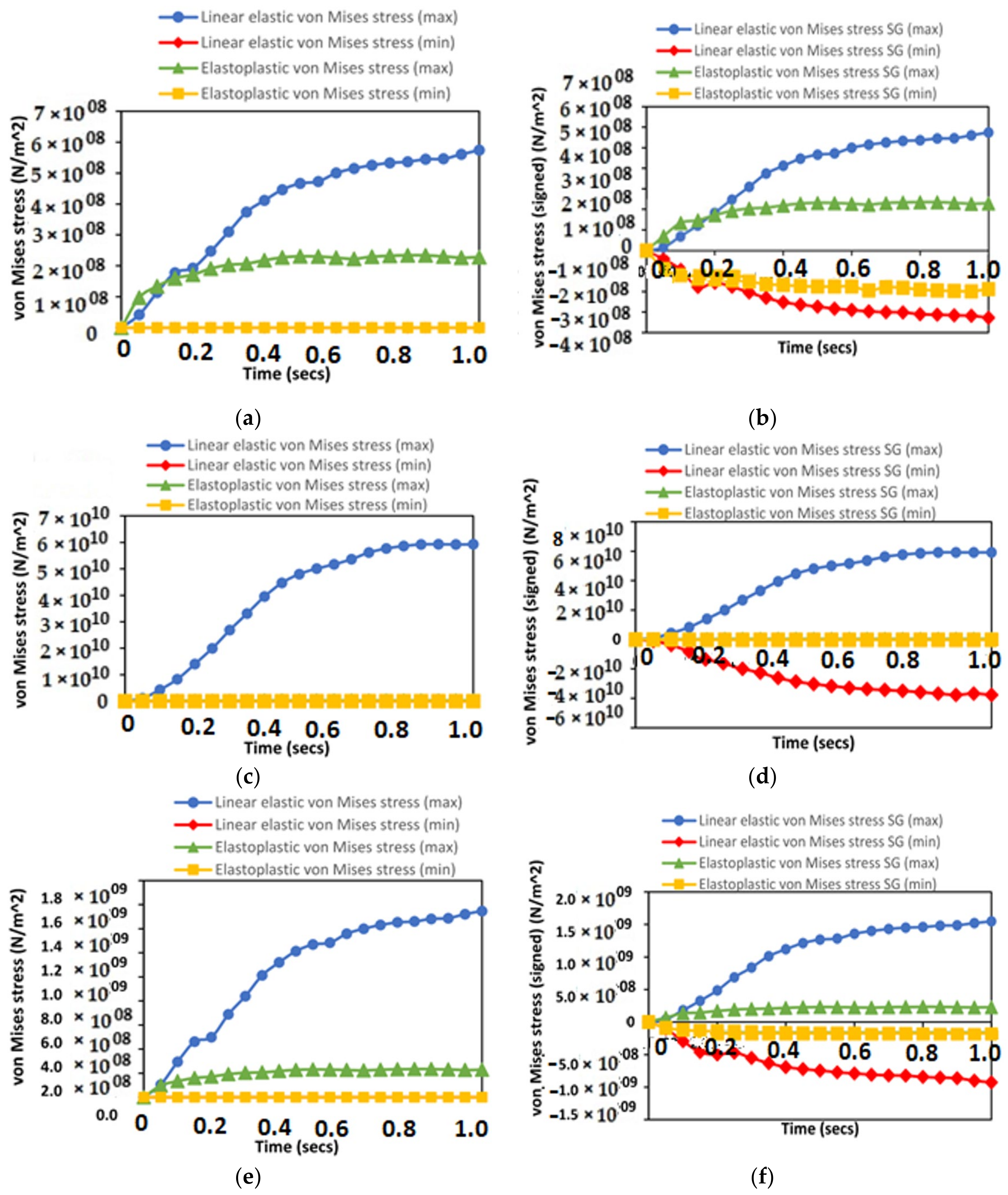
4.2. Result of Von Mises Stress (VMS)
4.3. Result of Reeling Time-Step Contour Study
4.4. Result of Contact Force Load
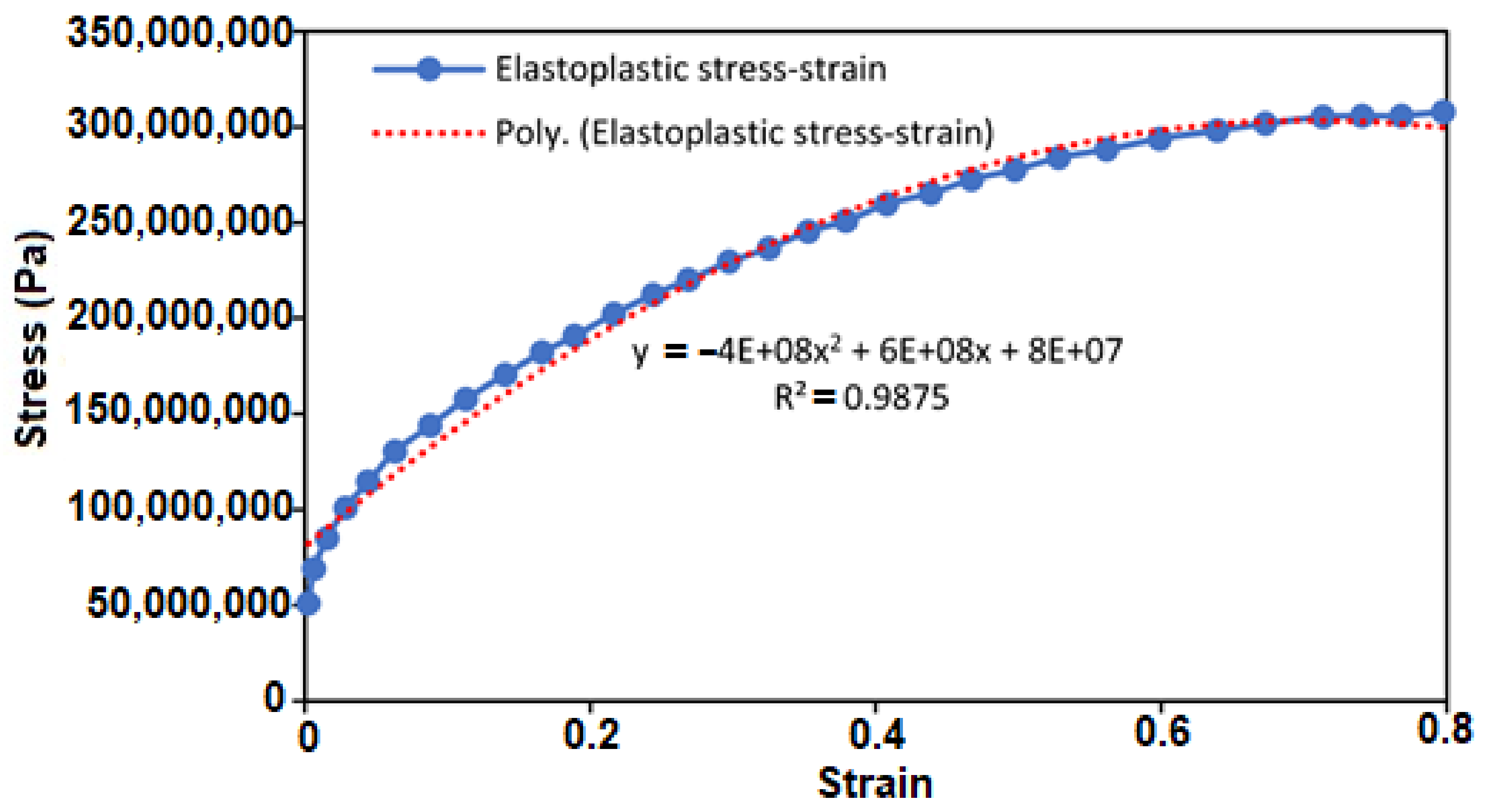
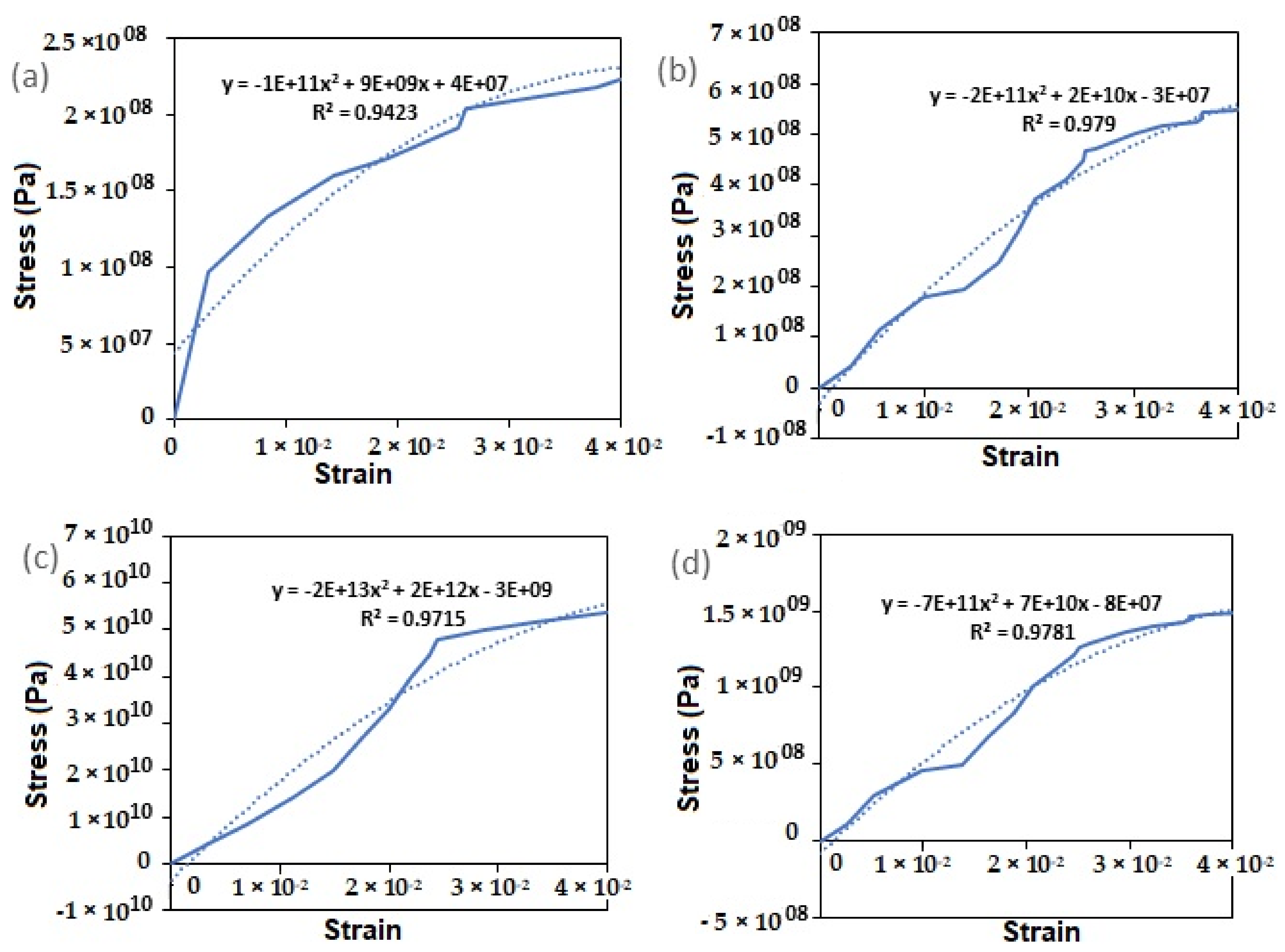
4.5. Result of Stress–Strain Relationship
4.6. Discussion of Results
- 1.
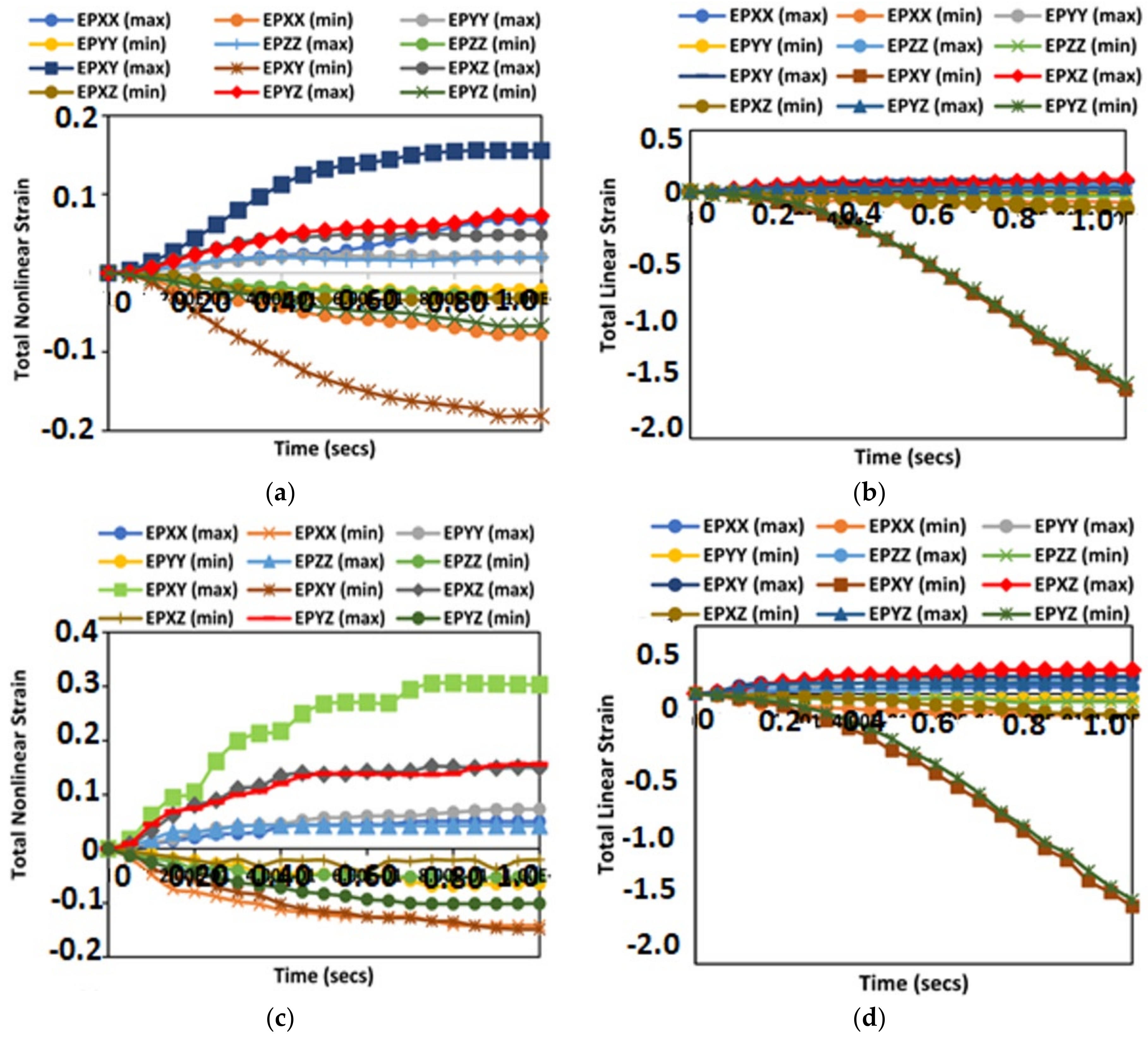
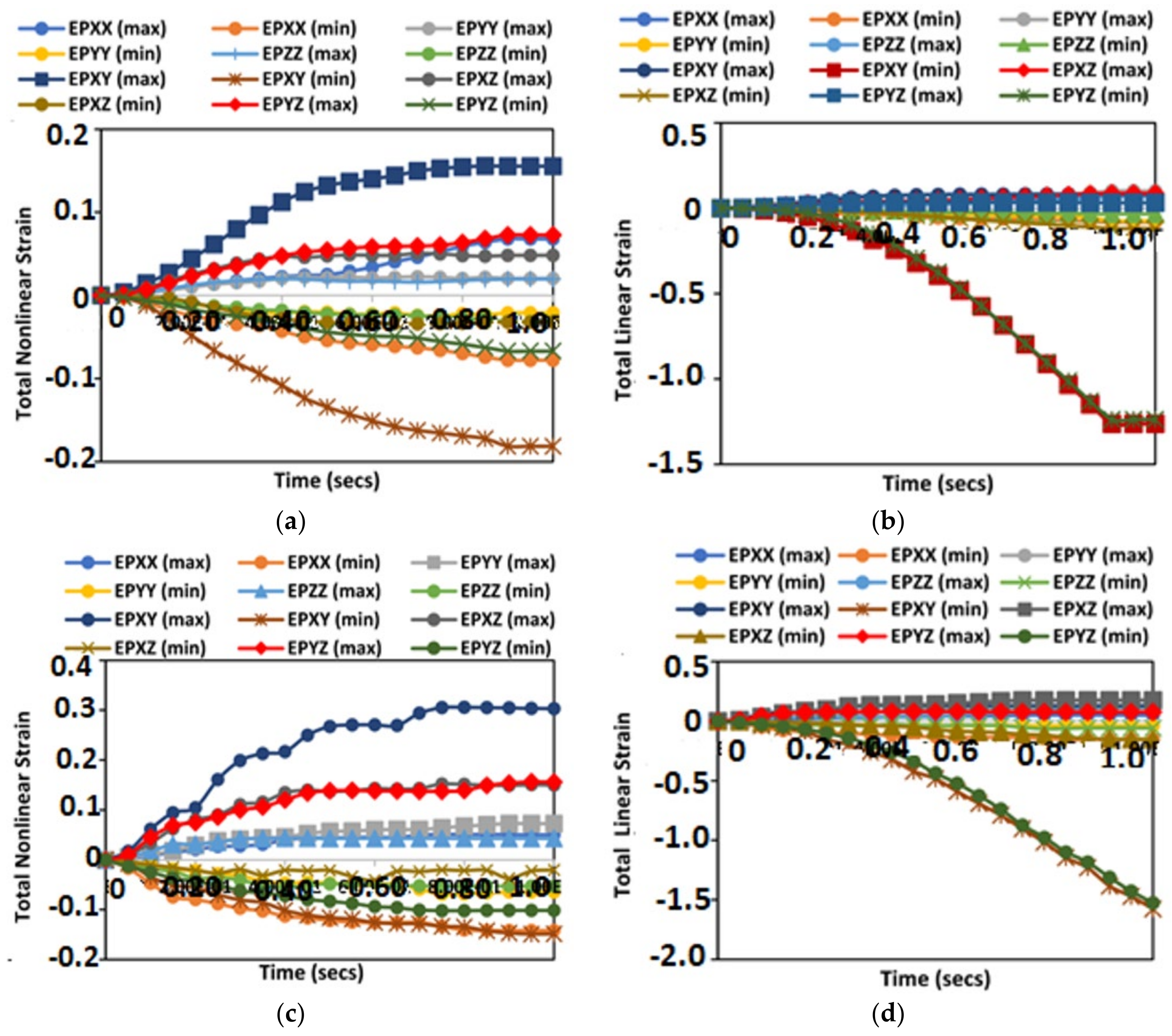
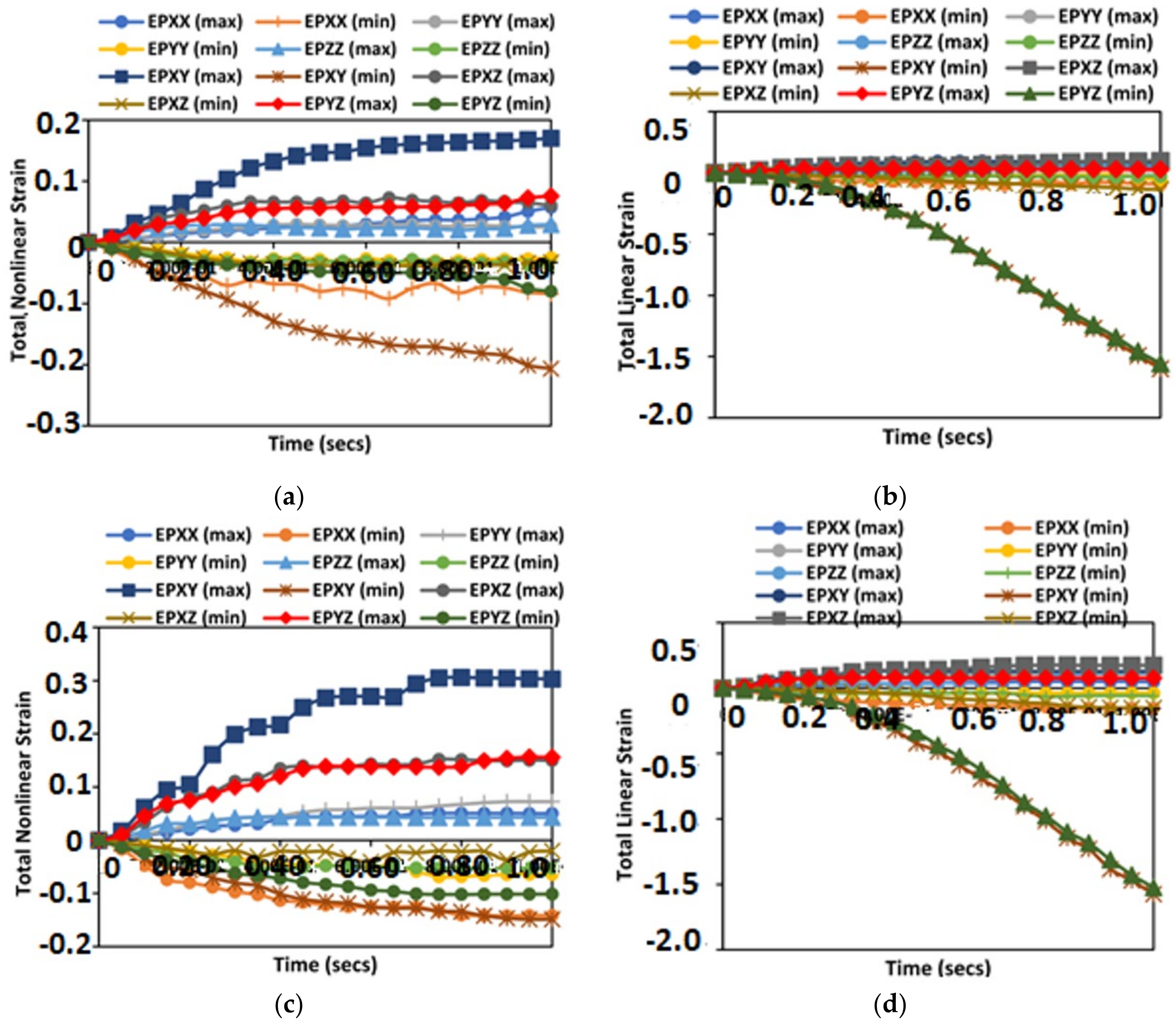
- For the reeling model, the results of Effective Plastic Strain (EPS) presented in Figure 7, Figure 8 and Figure 9 were obtained on the reeling hose using three composite models: epoxy composite, carbon fibre composite and Nylon PA66-GF composite. Additionally, two models were used: the elastoplastic model and the elastic linearity model. Assessing strains on each model using EPS, it is observed that the elastoplastic model had higher strains than the linear elastic model. Additionally, the maximum strain direction observed was the strain along EPXY at 1.73 × 10⁻¹. Along the hoop direction, the material will become more hardened, especially in a homogenised model, than along the longitudinal direction of the material. It is important to assess the strain during reeling by considering Accumulated Plastic Strain (APS), which is recommended at 2% according to DNV-OS-F101, which can increase due to the limitation of plastic deformation on the composite materials selected. However, the EPS was considered, which also gives an indication of the behaviour of the material and shows profiles of the strained and unstrained regions. Due to the locus of the yield stress on the hose section been reeled, the hose material has a plastic behaviour observed after reeling. As such, the total linear strain and total nonlinear strains were considered.
- 2.
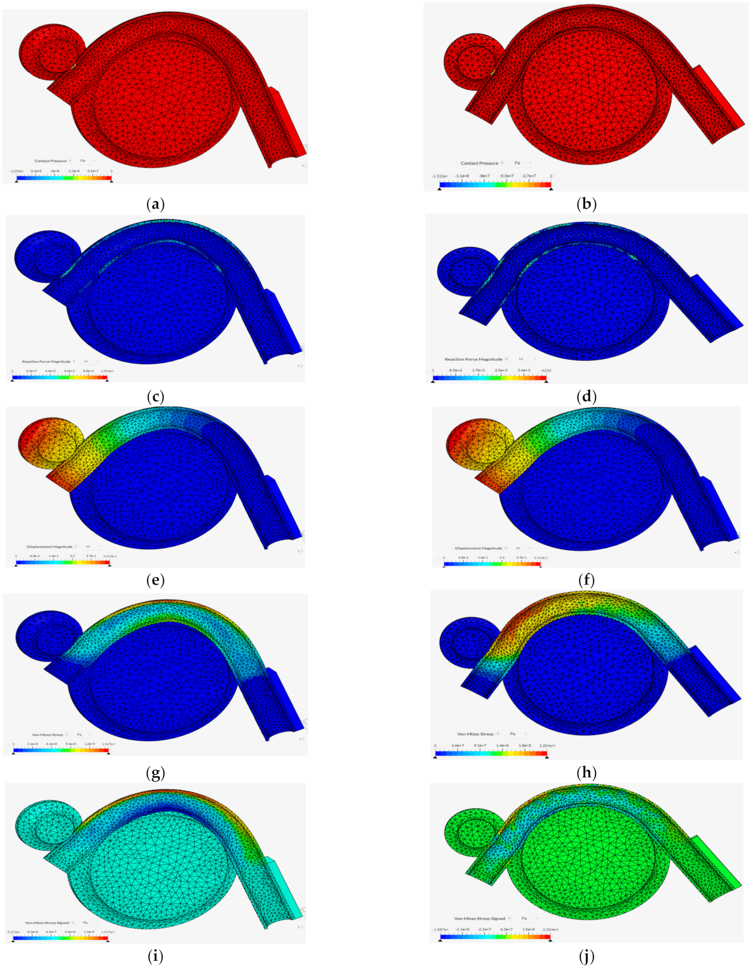
- The nonlinear analysis of the reeling operation as carried out in the Finite Element Analysis (FEA) is depicted in the order of the timesteps in Figure 13. It can be observed that the total strains started to propagate through the hose section as it was tensioned and spooled onto the reeling drum. Secondly, there is an accumulated plastic strain (APS) observed in the reeling operation which also transfers some strain energy onto the reeling drum as seen in these strain contour plots. Thus, it is necessary to investigate the contact pressure and the accumulated strain energy at these regions on the hoses. Additionally, it evident that the materials have different effects on the hose, as such two models were preferred—the carbon fibre and the nylon PA66GF composite models, as the strains showed a better consistency. However, further study is recommended on optimizing the models and reeling with unhomogenized hose models. Additionally, more studies on the application of this model and the global response of the reeling hose model are recommended on the effect of the reel drum and the HEV couplings load’s contact with the body of the FPSO.
- 3.
- The internal pressure and external pressure tests are very important aspect of the design of the reeling hoses. It was observed that the higher the pressure, the higher the von Mises stresses, maximum strains and maximum deformations on the reeling hose, as presented in Section 4.2, Section 4.3 and Section 4.4. However, this can be minimised by increasing the reinforcement of the reeling hose or by using lighter materials with a high strength–weight ratio, such as composites, or applying the hose hydrodynamic loads. A detailed study is recommended based on combined loading and the effect of the composite materials in the layers. Additionally, a global analysis on the reeling hose operation is recommended to investigate the effect of effective tension, bending moment, curvature and fluid content in the dynamic analysis of the offshore bonded composite hose.
- 4.
- From this study, it can be observed that if the reeling is done along the fibre direction of the reeling hose along its X–X direction, rather than its transverse direction or in-plane shear directions, it will yield along that direction. As such, failure of the reeling hose is also dependent on the angle of the orientation of the ply layers of the bonded hoses. However, the covalent bonds in the bonded hose are designed to prevent such failures. This study shows that the material effect of elastoplastic properties in elastomers used in modelling the hoses can also help to increase its elastic behaviour and durability, thus increasing its capacity, suitability and reeling ability.
- 5.
- The contact pressure is due to the reaction between the tensioner and the reeling drum, as seen in the model result in Figure 14a,b. During the reeling, the motion of the tensioner as it rolls onto the reeling drum to align it creates an opposite reaction, seen in the reaction force in Figure 14c,d. As this continues, the areas of the hose that are weakened start to deform and directional deformation starts to propagate in the direction of the composite layer. Considering both the elastic linearity and the elastoplastic model, the later seems to have an increase in hose deformation, contact pressure and reaction force than the linear elastic model, but this is relative as it depends on the stress–strain data from experiment. However, further research is recommended on the limit for the layers and on the interfacial stress of the offshore hose model.
5. Conclusions
Author Contributions
Funding
Data Availability Statement
Acknowledgments
Conflicts of Interest
References
- Dawood, A.A. A Study of Pipeline Response during Reel-Lay Installation. Master’s Thesis, Memorial University of Newfoundland, St John’s Newfoundland, NL, Canada, 2014. Available online: https://research.library.mun.ca/8055/1/thesis.pdf (accessed on 18 December 2021).
- Palmer, A.C.; King, R.A. Subsea Pipeline Engineering, 2nd ed.; PennWell Corporation: Tulsa, Oklahoma, USA, 2008. [Google Scholar]
- Bai, Y.; Bai, Q. Subsea Pipeline and Risers; Elsevier Publishers: Oxford, UK, 2005. [Google Scholar]
- Guo, B.; Song, S.; Ghalambor, A.; Lin, T.R.; Chacko, J. Offshore Pipelines; Elsevier Publishers: Oxford, UK, 2005. [Google Scholar]
- Amaechi, C.V.; Ye, J.; Hou, X.; Wang, F.-C. Sensitivity Studies on Offshore Submarine Hoses on CALM Buoy with Comparisons for Chinese-Lantern and Lazy-S Configuration OMAE2019-96755. In Proceedings of the 38th International Conference on Ocean, Offshore and Arctic Engineering, Glasgow, Scotland, 9–14 June 2019. [Google Scholar]
- Amaechi, C.V.; Wang, F.; Hou, X.; Ye, J. Strength of submarine hoses in Chinese-lantern configuration from hydrodynamic loads on CALM buoy. Ocean. Eng. 2019, 171, 429–442. [Google Scholar] [CrossRef] [Green Version]
- Amaechi, C.V.; Wang, F.; Ye, J. Numerical studies on CALM buoy motion responses, and the effect of buoy geometry cum skirt dimensions with its hydrodynamic waves-current interactions. Ocean Eng. 2022, 244, 110378. [Google Scholar] [CrossRef]
- Amaechi, C.V.; Wang, F.; Ye, J. Understanding the fluid-structure interaction from wave diffraction forces on CALM buoys: Numerical and analytical solutions. Ships Offshore Struct. 2021, in press. [Google Scholar] [CrossRef]
- Amaechi, C.V.; Wang, F.; Ye, J. Numerical Assessment on the Dynamic Behaviour of Submarine Hoses Attached to CALM Buoy Configured as Lazy-S under Water Waves. J. Mar. Sci. Eng. 2021, 9, 1130. [Google Scholar] [CrossRef]
- Amaechi, C.V.; Wang, F.; Ye, J. Mathematical Modelling of Bonded Marine Hoses for Single Point Mooring (SPM) Systems, with Catenary Anchor Leg Mooring (CALM) Buoy Application—A Review. J. Mar. Sci. Eng. 2021, 9, 1179. [Google Scholar] [CrossRef]
- Amaechi, C.V.; Chesterton, C.; Butler, H.O.; Wang, F.; Ye, J. An Overview on Bonded Marine Hoses for sustainable fluid transfer and (un)loading operations via Floating Offshore Structures (FOS). J. Mar. Sci. Eng. 2021, 9, 1236. [Google Scholar] [CrossRef]
- Amaechi, C.V.; Chesterton, C.; Butler, H.O.; Wang, F.; Ye, J. Review on the mechanics and design of marine bonded hoses for CALM buoys. Ocean Eng. J. 2021, 242, 1–32. [Google Scholar] [CrossRef]
- Amaechi, C.V.; Wang, F.; Ja’e, I.A.; Aboshio, A.; Odijie, A.C.; Ye, J. A literature review on the technologies of bonded hoses for marine application. Ships Offshore Struct. 2022. under review. [Google Scholar]
- Amaechi, C.V. Novel Design, Hydrodynamics and Mechanics of Marine Hoses in Oil/Gas Applications. Ph.D. Thesis, Lancaster University, Lancaster, UK, 2021. [Google Scholar]
- Chesterton, C. A Global and Local Analysis of Offshore Composite Material Reeling Pipeline Hose, with FPSO Mounted Reel Drum. Ph.D. Thesis, Lancaster University, Lancaster, UK, 2020. [Google Scholar]
- Szczotka, M. Dynamic analysis of offshore pipe laying operation using the reel method. Acta Mech. Sin. 2011, 27, 44–55. [Google Scholar] [CrossRef]
- Szczotka, M. Pipe laying simulation with an active reel drive. Ocean Eng. 2010, 37, 539–548. [Google Scholar] [CrossRef]
- Ahmetoglu, M.; Altan, T. Tube hydroforming: State-of-the-art and future trends. J. Mater. Process. Technol. 2000, 98, 25–33. [Google Scholar] [CrossRef]
- Kyriakides, S.; Corona, E. Mechanics of Offshore Pipelines: Volume 1: Buckling and Collapse; Elsevier Publishers: Oxford, UK, 2007. [Google Scholar]
- Yang, H.; Li, H.; Zhang, Z.; Zhan, M.; Liu, J.; Li, G. Advances and Trends on Tube Bending Forming Technologies. Chin. J. Aeronaut. 2012, 25, 1–12. [Google Scholar] [CrossRef] [Green Version]
- Lipski, W. Mechanical Lined Pipe—Installation by Reel-Lay. Page 17. 2011. Available online: https://www.yumpu.com/en/document/read/26877695/mechanical-lined-pipe-installation-by-reel-lay-subsea-uk (accessed on 15 November 2020).
- Toguyeni, G.A.; Banse, J. Mechanically lined pipe: Installation by reel-lay. In Proceedings of the Offshore Technology Conference, Houston, TX, USA, 30 April–3 May 2012. [Google Scholar] [CrossRef]
- Liu, K.X.; Liu, Y.L.; Yang, H.; Zhao, G.Y. Experimental study on cross-section distortion of thin-walled rectangular 3A21 aluminium alloy tube by rotary draw bending. Int. J. Mater. Prod. Technol. 2011, 42, 110–120. [Google Scholar] [CrossRef]
- Lu, S.; Fang, J.; Wang, K. Plastic deformation analysis and forming quality prediction of tube NC bending. Chin. J. Aeronaut. 2016, 29, 1436–1444. [Google Scholar] [CrossRef] [Green Version]
- McCann, S.; Evans, D.; Bannister, A.; Tan, H. Effects of Reeling on the Mechanical Properties of HFI Welded Pipes. Available online: https://www.pipeline-conference.com/sites/default/files/papers/PTC%202009%201.2%20Mc%20Cann.pdf (accessed on 18 December 2021).
- Chen, Y.; Tan, L.B.; Jaiman, R.K.; Sun, X.; Tay, T.E.; Tan, V.B.C. Global-Local Analysis of a Full-Scale Composite Riser During Vortex-Induced Vibration. In Proceedings of the ASME 2013 32nd International Conference on Ocean, Offshore and Arctic Engineering, Nantes, France, 9–14 June 2013. [Google Scholar] [CrossRef]
- Wang, C.; Shankar, K.; Morozov, E. Global design and analysis of deep sea FRP composite risers under combined environmental loads. Adv. Compos. Mater. 2017, 26, 79–98. [Google Scholar] [CrossRef]
- Wang, C.; Sun, M.; Shankar, K.; Xing, S.; Zhang, L. CFD Simulation of Vortex Induced Vibration for FRP Composite Riser with Different Modeling Methods. Appl. Sci. 2018, 8, 684. [Google Scholar] [CrossRef] [Green Version]
- Amaechi, C.V.; Gillett, N.; Odijie, A.C.; Hou, X.; Ye, J. Composite risers for deep waters using a numerical modelling approach. Compos. Struct. 2019, 210, 486–499. [Google Scholar] [CrossRef] [Green Version]
- Amaechi, C.V.; Ye, J. Local tailored design of deep water composite risers subjected to burst, collapse and tension loads. Ocean. Eng. 2021, in press. [Google Scholar] [CrossRef]
- Amaechi, C.V.; Gillett, N.; Odijie, A.C.; Wang, F.; Hou, X.; Ye, J. Local and Global Design of Composite Risers on Truss SPAR Platform in Deep waters. In Proceedings of the 5th International Conference on Mechanics of Composites, Lisbon, Portugal, 1–4 July 2019; pp. 1–3. [Google Scholar]
- Amaechi, C.V.; Ye, J. A numerical modeling approach to composite risers for deep waters. In Proceedings of the International Conference on Composite Structures, Paris, France, 4–7 September 2017. [Google Scholar]
- Pham, D.; Sridhar, N.; Qian, X.; Sobey, A.; Achintha, M.; Shenoi, A. A review on design, manufacture and mechanics of composite risers. Ocean. Eng. 2016, 112, 82–96. [Google Scholar] [CrossRef] [Green Version]
- Singh, M.; Ahmad, S. Fatigue Life Calculation of Deep Water Composite Production Risers by Rain Flow Cycle Counting Method. In Proceedings of the ASME 2015 34th International Conference on Ocean, Offshore and Arctic Engineering; Volume 5B: Pipeline and Riser Technology, St. John’s, NL, Canada, 31 May–5 June 2015. [Google Scholar] [CrossRef]
- Xu, Y.; Fang, P.; Bai, Y. Mechanical behavior of metallic strip flexible pipes during reeling operation. Mar. Struct. 2021, 77, 102942. [Google Scholar] [CrossRef]
- Williams, D. Analysis of Drilling Risers in Harsh and Deepwater Environments. 2010. Available online: https://www.offshore-mag.com/rigs-vessels/article/16763767/analysis-of-drilling-risers-in-harsh-and-deepwater-environments (accessed on 9 April 2021).
- Sohrabi, M.; Henderson, G.D.; Tehrani, D.H.; Danesh, A. Visualisation of Oil Recovery by Water Alternating Gas (WAG) Injection Using High Pressure Micromodels—Water-Wet System. In Proceedings of the SPE Annual Technical Conference and Exhibition, Dallas, TX, USA, 1–4 October 2000. [Google Scholar] [CrossRef]
- Ye, J.; Cai, H.; Liu, L.; Zhai, Z.; Amaechi, C.V.; Wang, Y.; Wan, L.; Yang, D.; Chen, X.; Ye, J. Microscale intrinsic properties of hybrid unidirectional/woven composite laminates: Part I experimental tests. Compos. Struct. 2021, 262, 113369. [Google Scholar] [CrossRef]
- Amaechi, C.V.; Odijie, C.; Sotayo, A.; Wang, F.; Hou, X.; Ye, J. Recycling of Renewable Composite Materials in the Offshore Industry. Encycl. Renew. Sustain. Mater. 2019, 2, 583–613. [Google Scholar] [CrossRef]
- Amaechi, C.V.; Odijie, C.; Etim, O.; Ye, J. Economic Aspects of Fiber Reinforced Polymer Composite Recycling. Encycl. Renew. Sustain. Mater. 2019, 2, 377–397. [Google Scholar] [CrossRef]
- Tang, N.C. Plastic-deformation analysis in tube bending. Int. J. Press. Vessel. Pip. 2000, 77, 751–759. [Google Scholar] [CrossRef]
- Popoola, L.T.; Grema, A.S.; Latinwo, K.; Gutti, B.; Balogun, A.S. Corrosion problems during oil and gas production and its mitigation. Int. J. Ind. Chem. 2013, 4, 35. [Google Scholar] [CrossRef] [Green Version]
- Raja, P.B.; Sethuraman, M.G. Natural products as corrosion inhibitor for metals in corrosive media—A review. Mater. Lett. 2008, 62, 113–116. [Google Scholar] [CrossRef]
- Szczygieł, B.; Kołodziej, M. Composite Ni/Al2O3 coatings and their corrosion resistance. Electrochim. Acta 2005, 50, 4188–4195. [Google Scholar] [CrossRef]
- Lassen, T.; Lem, A.I.; Imingen, G. Load response and finite element modelling of bonded offshore loading hoses. In Proceedings of the ASME 2014 33rd International Conference on Ocean, Offshore and Arctic Engineering, San Francisco, CA, USA, 8–13 June 2014. [Google Scholar] [CrossRef]
- Wu, W.; Zhang, P.; Zeng, X.; Jin, L.; Yao, S.; Luo, A.A. Bendability of the wrought magnesium alloy AM30 tubes using a rotary draw bender. Mater. Sci. Eng. A 2008, 486, 596–601. [Google Scholar] [CrossRef]
- Liu, K.X.; Liu, Y.L.; Yang, H. Experimental study on the effect of dies on wall thickness distribution in NC bending of thin-walled rectangular 3A21 aluminum alloy tube. Int. J. Adv. Manuf. Technol. 2013, 68, 1867–1874. [Google Scholar] [CrossRef]
- Corner, E. Bredero Shaw’s Complete Coating Assurance Model; World Pipelines: Farnham, UK, 2014; Available online: https://www.worldpipelines.com/product-news/21052014/bredero_shaws_complete_coating_assurance_model/ (accessed on 21 December 2021).
- Fang, J.; Lu, S.; Wang, K.; Gu, Q.; Shang, S. Springback behaviors of high strength stainless steel tube after numerical control rotary draw bending. IOP Conf. Ser. Mater. Sci. Eng. 2018, 423, 012184. [Google Scholar] [CrossRef]
- Fang, J.; Ouyang, F.; Lu, S.; Wang, K.; Min, X.; Xiao, B. Wall thinning behaviors of high strength 0Cr21Ni6Mn9N tube in numerical control bending considering variation of elastic modulus. Adv. Mech. Eng. 2021, 13, 16878140211021241. [Google Scholar] [CrossRef]
- Zhang, X.; Zhao, C.; Du, B.; Chen, D.; Li, Y.; Han, Z. Research on Hydraulic Push-Pull Bending Process of Ultra-Thin-Walled Tubes. Metals 2021, 11, 1932. [Google Scholar] [CrossRef]
- Zhang, Z.; Wu, J.; Guo, R.; Wang, M.; Li, F.; Guo, S.; Wang, Y.; Liu, W. A semi-analytical method for the springback prediction of thick-walled 3D tubes. Mater. Des. 2016, 99, 57–67. [Google Scholar] [CrossRef]
- Zhao, T.; Hu, Z. Numerical analysis of detaching and wrinkling of mechanically lined pipe during its spooling-on stage to the reel. Theor. Appl. Mech. Lett. 2015, 5, 205–209. [Google Scholar] [CrossRef] [Green Version]
- Qian, S.; Bai, Z.H.; Hu, W.T.; Lin, W.; Wang, T.L.; Zhang, J.S. Design and Key Process Simulation of a New Type of Pipe Bending Unit. Int. J. Simul. Model. 2021, 20, 559–570. [Google Scholar] [CrossRef]
- Gou, Y.; Shuang, Y.; Zhou, Y.; Mao, F.; Ding, X.; Cai, W.; Zhao, C. Effect of additional axial tension on formability of equal curvature-diameter bending without mandrel for 0Cr18Ni9 stainless steel tube. Mater. Res. Express 2019, 6, 066518. [Google Scholar] [CrossRef]
- Bilston, D.; Ruan, D.; Candido, A.; Durandet, Y. Parametric study of the cross-section shape of aluminium tubes in dynamic three-point bending. Thin-Walled Struct. 2019, 136, 315–322. [Google Scholar] [CrossRef]
- Cheng, X.; Wang, H.; El-Aty, A.A.; Tao, J.; Wei, W.; Qin, Y.; Gui, X. Cross-section deformation behaviors of a thin-walled rectangular tube of continuous varying radii in the free bending technology. Thin-Walled Struct. 2020, 150, 106670. [Google Scholar] [CrossRef]
- Guo, X.; Wei, W.; Xu, Y.; El-Aty, A.A.; Liu, H.; Wang, H.; Luo, X.; Tao, J. Wall thickness distribution of Cu–Al bimetallic tube based on free bending process. Int. J. Mech. Sci. 2019, 150, 12–19. [Google Scholar] [CrossRef]
- Wu, J.; Zhang, Z.; Shang, Q.; Li, F.; Wang, Y.; Hui, Y.; Fan, H. A method for investigating the springback behavior of 3D tubes. Int. J. Mech. Sci. 2017, 131, 191–204. [Google Scholar] [CrossRef]
- Jian, Z.; Xin, W.; Wenxian, T.; Fang, W.; Baoji, Y. Experimental and numerical buckling analysis of toroidal shell segments under uniform external pressure. Thin-Walled Struct. 2020, 150, 106689. [Google Scholar] [CrossRef]
- Li, H.; Yang, H.; Zhang, Z.Y.; Li, G.J.; Liu, N.; Welo, T. Multiple instability-constrained tube bending limits. J. Mater. Process. Technol. 2014, 214, 445–455. [Google Scholar] [CrossRef]
- Timoshenko, S.P. LXVI. On the correction for shear of the differential equation for transverse vibrations of prismatic bars. Lond. Edinb. Dublin Philos. Mag. J. Sci. 1921, 41, 744–746. [Google Scholar] [CrossRef] [Green Version]
- Timoshenko, S.P.X. On the transverse vibrations of bars of uniform cross-section. Lond. Edinb. Dublin Philos. Mag. J. Sci. 1922, 43, 125–131. [Google Scholar] [CrossRef] [Green Version]
- Timoshenko, S.P. Strength of Materials, Part II, 2nd ed.; McGraw Hill Publishers: New York, NY, USA, 1941. [Google Scholar]
- Focke, E.S. Reeling of Tight Fit Pipe. Ph.D. Thesis, Delft University of Technology, Delft, The Netherlands, 2007. Available online: http://resolver.tudelft.nl/uuid:21348ba3-bce9-4b01-98fd-f1a32fafaaa9 (accessed on 29 November 2020).
- Manouchehri, S. A Discussion of Practical Aspects of Reeled Flowline Installation. Available online: http://cyrusogr.com/files/OMAE2012-83649.pdf (accessed on 9 April 2021).
- Taams, V.J. The Onset of Pipeline Twist during Reel-Lay Operations. Master’s Thesis, Delft University of Technology, Delft, The Netherlands, 2016. Available online: http://resolver.tudelft.nl/uuid:9edd02a2-956f-414d-83c8-dae8b928f585 (accessed on 9 April 2021).
- Gao, Q.; Zhang, P.; Duan, M.; Yang, X.; Shi, W.; An, C.; Li, Z. Investigation on structural behavior of ring-stiffened composite offshore rubber hose under internal pressure. Appl. Ocean Res. 2018, 79, 7–19. [Google Scholar] [CrossRef]
- Amaechi, C.V.; Chesterton, C.; Butler, H.O.; Odijie, C.A.; Gu, Z.; Wang, F.; Hou, X.; Ye, J. Finite element modelling on the mechanical behaviour of Marine Bonded Composite Hose (MBCH) under burst and collapse. J. Mar. Sci. Eng. 2021. under review. [Google Scholar]
- Amaechi, C.V.; Wang, F.; Ye, J. Investigation on hydrodynamic characteristics, wave-current interaction, and sensitivity analysis of submarine hoses attached to a CALM buoy. J. Mar. Sci. Eng. 2021. under review. [Google Scholar]
- Amaechi, C.V.; Wang, F.; Ye, J. Experimental study on motion characterization of CALM buoy hose system under water waves. J. Mar. Sci. Eng. 2021. under review. [Google Scholar]
- API 17K. Specification for Bonded Flexible Pipe, 3rd ed.; American Petroleum Institute (API): Washington, DC, USA, 2017. [Google Scholar]
- Simscale. Simscale Documentation. 2021. Available online: https://www.simscale.com/docs/ (accessed on 18 December 2021).
- Tresca, H. Sur l’Ecoulement des Corps Solides Soumis a de Fortes Pressions. C. R. Acad. Sci. Paris 1864, 59, 754. [Google Scholar]
- Huber, M.T. Właściwa praca odkształcenia jako miara wyteżenia materiału. Czasopismo Techniczne 1904, 22, 38–40, 49–50, 61–62, 80–81. [Google Scholar]
- Von Mises, R. Mechanik der Festen Korper im Plastisch Deformablen Zustand. Nachr. Ges. Wiss. Gott. 1913, 1913, 582–592. [Google Scholar]
- Dowling, N.E.; Kampe, S.L.; Kral, M.V. Mechanical Behavior of Materials, 5th ed.; Pearson, Prentice Hall: Hoboken, NY, USA, 2019. [Google Scholar]
- Hencky, H.Z. Zur Theorie Plasticher Deformationen und der Hierdurch im Material Hervorgerufenen Nachspannungen. Z. Angerw. Math. Mech. 1924, 4, 323. [Google Scholar] [CrossRef]
- Taylor, G.I.; Quinney, H. The Plastic Distortion of Metals. Philos. Trans. R. Soc. Lond. 1931, 230, 323–363. [Google Scholar] [CrossRef]


| Parameter | Value | Unit |
|---|---|---|
| Tubular Pipe Outer radius | 0.025 | m |
| Tubular Pipe Inner radius | 0.02 | m |
| Length of Tube model | 0.45 | m |
| Radius of reel | 0.09 | m |
| Outer Reel radius | 0.11 | m |
| Tensioner roller radius | 0.02 | m |
| Material | Density (kg/m3) | Youngs Modulus (Pa) | Bulk Modulus (Pa) | Shear Modulus (Pa) | Compressive Yield Strength (Pa) | Tensile Yield Strength (Pa) | Tensile Ultimate Strength (Pa) | Poisons Ratio |
|---|---|---|---|---|---|---|---|---|
| Resin Polyester * | 1200 | 3 × 10⁹ | 2.7174 × 10⁹ | 1.1398 × 10⁹ | 1.41 × 10⁸ | 1.28 × 10⁸ | 5.18 × 10⁷ | 0.316 |
| Nylon PA66 * | 1140 | 1.06 × 10⁹ | 1.1778 × 10⁹ | 3.9259 × 10⁸ | 2.32 × 10⁹ | 4.31 × 10⁷ | 4.97 × 10⁷ | 0.35 |
| Nylon PA6/6 glass fiber reinforced (PA66-GF) * | 1360 | 6.82 × 10⁹ | 7.5778 × 10⁹ | 2.5259 × 10⁹ | 3.45 × 10⁷ | 1.39 × 10⁸ | 1.49 × 10⁸ | 0.35 |
| Structural Steel * | 7850 | 2 × 10¹¹ | 1.6667 × 10¹¹ | 7.6923 × 10¹⁰ | 2.5 × 10⁸ | 2.5 × 10⁸ | 4.6 × 10⁸ | 0.3 |
| Carbon fibre Composite (290GPa) * | 1810 | 2.9 × 10¹¹ | 2.45 × 10¹¹ | 9 × 10⁹ | 5.7 × 10⁸ | 4.2 × 10⁹ | 6 × 10⁸ | 0.3 |
| Epoxy Composite | 1400 | 2.5 × 10⁹ | 3.16 × 10⁹ | 4.12 × 10⁹ | 7.36 × 10⁸ | 1.23 × 10⁸ | 9.19 × 10⁸ | 0.3 |
| tetEdgeRatio | min: 1.0376168721694845 |
| max: 3.093679141141022 | |
| average: 1.5687727603714354 | |
| standard deviation 0.24089263488291165 | |
| median: 1.5297991927985433 | |
| 0-th percentile: 1.0376168721694845 | |
| 20-th percentile: 1.3834451887266506 | |
| 40-th percentile: 1.4840930791225821 | |
| 60-th percentile: 1.5785868300256487 | |
| 80-th percentile: 1.704422472523748 | |
| 100-th percentile: 3.093679141141022 | |
| triMaxAngle | min: 60.05482321990108 |
| max: 127.35381485025293 | |
| average: 75.16684693915764 | |
| standard deviation 9.776579039415518 | |
| median: 73.29453691831603 | |
| 0-th percentile: 60.05482321990108 | |
| 20-th percentile: 66.44694506447732 | |
| 40-th percentile: 71.02152546319378 | |
| 60-th percentile: 75.96067124402948 | |
| 80-th percentile: 83.28559263336597 | |
| 100-th percentile: 127.35381485025293 | |
| triMinAngle | min: 19.35217668366241 |
| max: 59.91366406827127 | |
| average: 46.70468441834977 | |
| standard deviation 7.28819486436269 | |
| median: 47.247565915521015 | |
| 0-th percentile: 19.35217668366241 | |
| 20-th percentile: 40.614183026171084 | |
| 40-th percentile: 45.26696822391534 | |
| 60-th percentile: 49.251397045870696 | |
| 80-th percentile: 53.39908813577736 | |
| 100-th percentile: 59.91366406827127 | |
| volumeRatio | min: 1.000000006324029 |
| max: 3.961157286070154 | |
| average: 1.2483925373820084 | |
| standard deviation 0.2594881050104104 | |
| median: 1.1690056215931153 | |
| 0-th percentile: 1.000000006324029 | |
| 20-th percentile: 1.046584535039526 | |
| 40-th percentile: 1.1233096677153573 | |
| 60-th percentile: 1.2269723611496575 | |
| 80-th percentile: 1.3949996092464683 | |
| 100-th percentile: 3.961157286070154 | |
| tetAspectRatio | min: 1.0139867699918363 |
| max: 4.118610423840127 | |
| average: 1.4166774878493793 | |
| standard deviation 0.2220781989410356 | |
| median: 1.3715678703595808 | |
| 0-th percentile: 1.0139867699918363 | |
| 20-th percentile: 1.2377215653270137 | |
| 40-th percentile: 1.3283845255084676 | |
| 60-th percentile: 1.4231277037383703 | |
| 80-th percentile: 1.5670293674134164 | |
| 100-th percentile: 4.118610423840127 |
Publisher’s Note: MDPI stays neutral with regard to jurisdictional claims in published maps and institutional affiliations. |
© 2022 by the authors. Licensee MDPI, Basel, Switzerland. This article is an open access article distributed under the terms and conditions of the Creative Commons Attribution (CC BY) license (https://creativecommons.org/licenses/by/4.0/).
Share and Cite
Amaechi, C.V.; Adefuye, E.F.; Oyetunji, A.K.; Ja’e, I.A.; Adelusi, I.; Odijie, A.C.; Wang, F. Numerical Study on Plastic Strain Distributions and Mechanical Behaviour of a Tube under Bending. Inventions 2022, 7, 9. https://doi.org/10.3390/inventions7010009
Amaechi CV, Adefuye EF, Oyetunji AK, Ja’e IA, Adelusi I, Odijie AC, Wang F. Numerical Study on Plastic Strain Distributions and Mechanical Behaviour of a Tube under Bending. Inventions. 2022; 7(1):9. https://doi.org/10.3390/inventions7010009
Chicago/Turabian StyleAmaechi, Chiemela Victor, Emmanuel Folarin Adefuye, Abiodun Kolawole Oyetunji, Idris Ahmed Ja’e, Ibitoye Adelusi, Agbomerie Charles Odijie, and Facheng Wang. 2022. "Numerical Study on Plastic Strain Distributions and Mechanical Behaviour of a Tube under Bending" Inventions 7, no. 1: 9. https://doi.org/10.3390/inventions7010009
APA StyleAmaechi, C. V., Adefuye, E. F., Oyetunji, A. K., Ja’e, I. A., Adelusi, I., Odijie, A. C., & Wang, F. (2022). Numerical Study on Plastic Strain Distributions and Mechanical Behaviour of a Tube under Bending. Inventions, 7(1), 9. https://doi.org/10.3390/inventions7010009