Tutorial

A Tutorial on Robust Control, Adaptive Control and Robust Adaptive Control—Application to Robotic Manipulators

Lassonde School of Engineering, York University, 4700 Keele Street, Toronto, ON M3J 1P3, Canada
Inventions 2019, 4(3), 49; https://doi.org/10.3390/inventions4030049
Submission received: 4 July 2019 / Revised: 7 August 2019 / Accepted: 20 August 2019 / Published: 23 August 2019
(This article belongs to the Special Issue Automatic Control and System Theory)

Abstract

:
A tutorial on robust control, adaptive control, robust adaptive control and adaptive control of robotic manipulators is presented in a systematic manner. Some limitations of the above methods are also illustrated. The relationships between the robust control, adaptive control and robust adaptive control are demonstrated. Basic information on the joint space control, operational space control and force control is also given. This tutorial summarizes the most advanced control techniques currently in use in a very simple manner, and applies to robotic manipulators, which can provide an informative guideline for students who have little knowledge of controls or who want to understand the adaptive control of robotics in a systematic way.

1. Introduction

Robotics have been widely utilized in many areas, such as manufacturing, service, medical, space, underwater, the military, etc. Research on robotics has been underway for decades. Research on kinematics [1], synthesizing design [2,3], workspace analysis [4,5], singularity analysis [6,7], stiffness performance [8], dynamics [9], control designs and novel applications of robotics [10,11,12] has attracted much attention. One of the most important topics nowadays is the control issue. In this paper, a general review and discussion of robust control, adaptive control, robust adaptive control and adaptive control of robotic manipulators are presented.
In order to study the control problem, one needs to have a dynamic model; in order to have a dynamic model, one must first deal with the basic kinematics. As illustrated in Figure 1, the relationship between kinematic, dynamic, and control is simply illustrated. For the kinematics issue, the purpose of kinematic modelling is to determine where the joint should be positioned in order to achieve a desired trajectory; through dynamic modelling, one knows how much torque is necessary in each joint in order to have the corresponding joint position. For the dynamic modelling issue, there are two main methods of dynamic modelling, the Lagrange method and the Newton‒Euler method. The Lagrange method is an energy-based modelling approach and it is the most widely used technique. Usually the dynamic equations of robotic manipulators are very complex and highly nonlinear. The purpose of dynamic modelling is to determined how much torque one needs to apply to each joint so that a desired trajectory can be achieved.

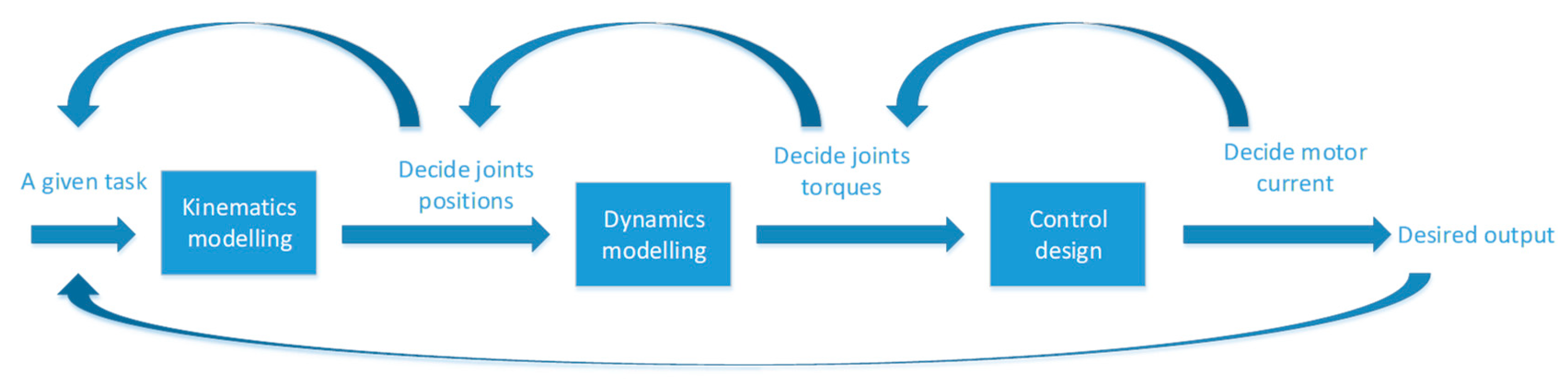
2. Joint Space Control and Operational Space Control

Joint space control: the drawback of joint space control for a multi-DOF robotic manipulator is that we need to do an inverse kinematic calculation, which is very cumbersome as it is known that the inverse kinematic for a serial manipulator is complicated compared to a forward kinematic calculation. Furthermore, since for the joint space control one first needs to imagine the final goal position for the end-effector, we have to do an inverse kinematic calculation to determine what the corresponding joint angles need to be. Because of this, another drawback of joint space control is that in real time, when a robotic manipulator meets an unexpected obstacle, one has to redo the whole motion planning. Due to the above limitations, operational space control is therefore put forward by Khatib [13].
Operational space control: by applying a force F at the end-effector, and through multiplying a JT, one can calculate the corresponding joint torque τ needed in order to achieve the task space control:
τ = J T F .
In operational space control, one has motion control and force control. Motion control is to control the motion of the end-effector, and force control is to control how much force the end-effector has. In some situations (e.g., a manipulator cleans a window), motion control and force control need to be considered at the same time. In this way, the effector has the proper force at the effector so that the effector will not break the window. If a robot is interacting with the environment, we have to deal with the force control and motion control. Unified motion and force control were studied in [13]. A recent study [14] focused on the compliant motion and force control, where the robot end-effector is controlled by the contacting force; this type of control does not need trajectory planning.

3. Robust Control

The main idea behind the robust control is to replace the nth-order problem by a first-order problem. The first step is to create an intermediate variable, which we denote as S. This intermediate variable S needs to satisfy the following two conditions: (1) S contains the control law u, and (2) S 0 x ( t ) = 0 , where x ( t ) is the difference between the real value x ( t ) and the desired value x d ( t ) . The intermediate variable S is chosen as: S = ( d d t + λ ) n 1 x , where λ is a positive constant. So, for a second-order system, we choose S as S = x + λ x .
Furthermore, for a second-order system, if | S | 0 , then the corresponding x ϕ λ ; and for an nth-order system, if | S | 0 , then the corresponding x ϕ λ n 1 .
Taking the following as an example (second-order system). A second-order system x + a ( t ) x 2 cos 3 x = u , with 1 a ( t ) 2 . A standard second-order system is usually written as follows:
x = f ( x , t ) + b ( x , t ) u .
Thus x + a ( t ) x 2 cos 3 x = u can be written as follows:
x = a ( t ) x 2 cos 3 x + u .
Since the range for a ( t ) is 1 < a ( t ) < 2 , we choose the middle value, i.e.,
f = 1.5 x 2 cos 3 x ,
So that,
F = 0.5 x 2 | cos 3 x | .
The intermediate variable S is as follows:
S = x + λ x .
Then
S = x + λ x = f ( x , t ) + b ( x , t ) u x d + λ x .
Here u is chosen such that the following condition is met:
1 2 d d t S 2 η | S | ,
where η is a positive constant. The above condition is called a sliding condition.
Since
S = x + λ x = f + u x d + λ x ,
we define u such that S = 0 ,
u = f + x d λ x .
With u = u ,
S = f f .
So 1 2 d d t S 2 = S S = S ( f f ) , we can see that S ( f f ) and η | S | cannot be compared, thus the control law is rewritten as follows:
u = u k sgn ( S ) .
Thus 1 2 d d t S 2 = S S = S ( f f ) k | S | , in order to make S ( f f ) k | S | η | S | , we choose k = F + η .
So, the control law can be written as follows:
u = u k sgn ( S ) = f + x d λ x k sgn ( S ) = 1.5 x 2 cos 3 x + x d λ x ( 0.5 x 2 | cos 3 x | + η ) sgn ( x + λ x )
The drawback of the above approach is that since the control law u = u k sgn ( S ) incorporates the sgn ( S ) , there is control chattering. One possible solution is for the control law to be changed such that u = u k s a t ( S ϕ ) ; in this way, the control chattering can be eliminated, but there will be a small tracking error. Another possible solution is that instead of adding a k sgn ( S ) in the control law, which produces control chattering, maybe we can do it in a different way. The problem lies in the fact that when we choose control law u = u , the sliding condition cannot be satisfied. Future work should be focused on this question: how can we meet the sliding condition without adding k sgn ( S ) ?
To go one step further, in the robust control, we know that the parameters are unknown and are bounded within a certain range. If the unknown parameters can be described as unknown constants, we can add an adaptation to make the system work as if the unknown constants are known. This is the so-called adaptive control, which is described in the following section.

4. Adaptive Control

Here we use the following pendulum (which can also be seen as a 1-DOF robot; an example is shown in Figure 2) to illustrate the adaptive control.
First, the dynamic equation is as follows:
J x + b x | x | + m g l sin x = u ,
where b x | x | is the dragging term. Here the unknown constants are J , b and m g l , and we write them in a matrix form as:
a = [ a 1 a 2 a 3 ] = [ J b m g l ] .
We choose the Lyapunov candidate function as follows:
V = 1 2 J S 2 ,
where S is the intermediate variable. Taking the time derivative of the above equation, we have
V = S J S = S ( u y a )
where y is a known function and is written as y = [ x r x | x | sin x ] ; a is an unknown constant and is written as above.
We choose the control law as follows:
u = y a k S ,
where k is a positive constant and the term k S is actually a PD control, and the term y a is used to cancel the dynamics. Plugging the control law from Equation (18) into Equation (17), we get:
V = S J S = S ( u y a ) = k S 2 + S y a
where a = a a , a means the estimate of a , so a means the parameter estimation error. From the above equation, we see that there is a S y a . If this S y a does not exist, we have V 0 S 0 x = 0 and x = 0 , according to Barbalat’s lemma. So, the question is how to eliminate this S y a . If one adds a term to the Lyapunov candidate function (so when we take the time derivative of this term, S y a , and the time derivative of the added term can be made to equal 0), then the above problem is solved. So, we add a term 1 2 a T P 1 a to the Lyapunov candidate function, where P is constant (e.g., can be considered an identity matrix), and thus the Lyapunov candidate function can be rewritten as follows. The reason 1 2 a T P 1 a is added is that in the Lyapunov candidate function, 1 2 J S 2 can be considered as the square of the parameter tracking error, so by adding the square of parameter estimation error, we might get rid of the term S y a by using the adaptation law [15].
V = 1 2 J S 2 + 1 2 a T P 1 a
V = S J S + a T P 1 a = S ( u y a ) + a T P 1 a = k S 2 + S y a + a T P 1 a
Making the last two terms equal to 0, we have
S y a + a T P 1 a = 0 a = P y T S
a = P y T S is our adaptation law. It should be further noted that if one integrates both sides of the adaptation law and plugs them into Equation (22), the adaptive control becomes PID control. As an extra note, Barbalat’s lemma is only used for a non-autonomous system x = f ( x , t ) . It is stated that if a scalar V ( x , t ) is lower bounded and d d t V ( x , t ) 0 , then d d t V ( x , t ) 0 as t .
As a case study and numerical example, Figure 3 shows the joint output under the adaptive control and PD control, respectively, for two different payload scenarios. The proportional and derivative gains of the PD control are selected as 5 and 3, respectively, here as a case study. It is observed that by using the adaptive control, the joint output becomes more robust and converges more quickly than that of the PD control. Compared to the PD control, which takes about 38 s to converge to 0, the adaptive control case converges to 0 within 20 s. This indicates that the adaptive control is more robust than the traditional PD control [16]. By applying different gains, similar results can be obtained. The same goes for joint 2. Note that the above adaptation law can be considered an integral control if one integrates both sides of Equation (22). That is why we did not include the integral term of the traditional PD control.
Here we showed the pure adaptive control, i.e., unknown parameters being described by an unknown constant. If we combine the adaptive control and robust control, the unknown parameters are partitioned into two parts. The unknown parameters can be described by an unknown constant, while the unknown parameters can only be described by certain bounds; this is what we are going to focus in the next section, i.e., robust adaptive control.

5. Robust Adaptive Control

We use the above pendulum as an example, but the dynamic equation is changed to the following:
J x + b x | x | + m g l sin x = f ( x , x , t ) + u ,
where f is bounded by | f ( x , t ) f ( x , t ) | F , f ( x , t ) and F are known.
The goal here is to make the system behave as if the unknown constant a were known, in other words, as if we only have to be robust to f ( x , t ) .
Here we define a variable S Δ , such that | S | ϕ S Δ = 0 .
Similarly, the Lyapunov candidate function is chosen as follows:
V = 1 2 J S Δ 2 .
We choose the control law as follows:
u = y a k s a t ( S ϕ ) f ( x , t ) .
The first term is used to cancel the dynamics, the second term is a stabilization term, and the third term is used to cancel the f term. f represents, for example, the unknown friction term of the dynamics, where f represents the estimate of f . The abbreviation part lists some relevant terms used.
Taking the time derivative of the above Lyapunov candidate function, we have:
V = S Δ J S = S Δ ( k s a t ( S ϕ ) + y a + f ( x , t ) f ( x , t ) ) = k | S Δ | + S Δ y a + S Δ ( f f )
We can see that the above equation has two extra terms, S Δ y a and S Δ ( f f ) . Using a similar approach, we add something to the Lyapunov candidate function, then we have:
V = 1 2 J S Δ 2 + 1 2 a T P 1 a .
V = S Δ J S + a T P 1 a = S Δ ( k s a t ( S ϕ ) + y a + f ( x , t ) f ( x , t ) ) + a T P 1 a = k | S Δ | + S Δ y a + S Δ ( f f ) + a T P 1 a
By making S Δ y a + a T P 1 a = 0 , we have the following:
S Δ y a + a T P 1 a = 0 a = P y T S Δ
and
V = k | S Δ | + S Δ ( f f ) .
Selecting k = F + η , we have
V = k | S Δ | + S Δ ( f f ) = ( F + η ) | S Δ | + S Δ ( f f )
Thus,
V η | S Δ | 0 .
According to Barbalat’s lemma, V 0 S Δ 0 .

6. Adaptive Control

The reason the PD controller works is that it mimics the spring-damper system, and according to the global invariant set theorem, the system can globally tend to the stability point. Here we give detailed proof of why PD control works in the position control problem. Before proceeding, it should be noted that the “I” term in the PID control can actually be seen as adaptive control.
It is known that the PD controller can be described as follows:
τ = K P q K D q ,
where q = q q d and q d means the joint desired position. Considering the virtual physics, the PD controller can be seen as a virtual spring (P) and virtual damper (D). The reason why the PD controller works can be traced to the Lyapunov theory. The first step is to have a Lyapunov candidate function as follows:
V = kinetic   energy   +   potential   energy = 1 2 q T H ( q ) q + 1 2 q T K P q
Therefore,
V = q T ( τ D q ) + q T K P q .
Plugging the control law τ = K P q K D q into the above equation, we get
V = q T ( K D + D ) q 0
According to the global invariant set theorem, V = 0 q = 0 H q = K P q q = H 1 K P q 0 unless q = 0 ; in other words, unless q equals q d . This shows that, starting anywhere, if we apply the PD controller, the system globally tends to q = q d .
The control issue has been developed in the last few decades. PID control (usually PD control) is widely used in industry due to its simplicity. In controlling a robot end-effector position, industries use the PD controller in each joint of a robotic manipulator to control the robot end-effector goal position in order to accomplish a desired position control. As previously mentioned, the reason the PD controller works for controlling a goal position of a robot end-effector in industries nowadays is that the PD control mimics a spring-damper system (as illustrated in Figure 4). According to the global invariant set theorem (an extended version of the Lyapunov theorem), the system can globally tend to the stability point. However, if a robot needs to have a specified trajectory or fast motion control, the PD control approach is not good enough to handle the above situations since it does not tell you what is going on in the process of moving a robot. A more advanced control system is therefore required—for example, adaptive control [17]. As in [18], for a 2-DOF serial manipulator with revolute joints, as shown in Figure 5, first, we have the dynamic equation as follows:
H ( q ) q + C ( q , q ) q + D ( q , q ) q + g ( q ) = τ ,
where q is the joint angles, H ( q ) is the inertia matrix, C ( q , q ) q is the centripetal and Coriolis torque, D ( q , q ) q is the friction, and g ( q ) is the gravitational torque.
First of all, the Lyapunov candidate function is chosen as follows:
V = 1 2 S T H ( q ) S ,
where S = q + λ q and q = q q d . Then one can calculate V as follows:
V = S T ( τ H q r C q r D q g ) .
The above H q r C q r D q g can be written as y ( q , q , q r , q r ) a , where y ( q , q , q r , q r ) is known and a is unknown constant, i.e., H q r C q r D q g can be written as a known function times an unknown constant:
V = S T ( τ y ( q , q , q r , q r ) a ) .
By choosing the control law
τ = y a K D S ,
we have
V = S T K D S + S T y a .
It is noted that we have an extra S T y a ; in order to eliminate this term, another term 1 2 a T P 1 a is added to the above Lyapunov candidate function, then the Lyapunov candidate function can be rewritten as follows:
V = 1 2 S T H ( q ) S + 1 2 a T P 1 a .
Then
V = S T K D S + S T y a + 1 2 a T P 1 a ,
where a = a a . So, by making the last two terms equal to 0, i.e., by choosing the adaptation law as follows:
S T y a + 1 2 a T P 1 a = 0 a = P y S
we have
V = S T K D S .
Based on Barbalat’s lemma, when V 0 S 0 q 0 and q 0 .
Similarly, as a case study and numerical example, Figure 6 shows the joint 1 and joint 2 outputs under adaptive control and PD control, respectively. The proportional and derivative gains of the PD control are selected as 5 and 3, respectively, here as a case study. It is observed that by using the adaptive control, the joint output converges more quickly than that of the PD control, as with the one-DOF case. As compared with the PD control, which takes about 16 s to converge to 0, the adaptive control case converges to 0 within 9 s. This indicates that the adaptive control here is more robust than the traditional PD control [16]. The same goes for joint 1. Again, through applying different gains, similar results can be proven.
Sometimes, friction is useful for the stability of the system. As a case study, a 2-DOF underwater robot is studied here. As shown below in Figure 7, a 2-DOF robot arm is attached to an underwater vehicle. The mass of the rocks and water resistance are unknown. Here we will design a control system for the two joints to make the robot arm work properly even though all the parameters (e.g., mass matrix, friction) are unknown. The following section will illustrate how friction can be useful in the stability performance.
It is known that S = q + λ q = q q r , so in the dynamic equation, D q can be written as D q = D q r + D S ; thus, the dynamic equation can be rewritten as follows:
H ( q ) q + C ( q , q ) q + D ( q , q ) q r + g ( q ) = τ D S .
So, instead of eliminating the friction term as illustrated above, one can use the friction term instead. In the previous approach, one has H q r + C q r + D q + g = y a , where a is an unknown constant as described in Equation (15). In this case, one has H q r + C q r + D q r + g = y n e w a . Furthermore, in the previous approach, V = S T K D S . In this case, V = S T ( K D + D ) S , and the control law and the adaptation law are as follows:
τ = y n e w a K D S
a = P y n e w T S .
However, there are two main limitations to the above method: first, i in a ( t ) = a ( t ) a , one assumes that the constant a does not change over time. This is a limitation. This is only valid when a changes very slowly with respect to time, or when a robot grasps a load (because at the moment when the robot grasps a load, we can assume that the time sets back to 0 and a becomes constant). This condition will not be valid in some situations where a is changing fast with respect to time (e.g., when a robot does fast or constant loading and unloading tasks). If this is the case, we need to remodel a . The second limitation is that the above approach is joint space control, which is known to require pre-calculation of the inverse kinematic of the serial manipulators, which is very cumbersome.
The above stability analysis is based on the Lyapunov theory. Another approach to the stability analysis of adaptive control is based on the hyperstability theory. Examples can be found in [19]. Some recent studies dealing with the design of adaptive controllers for nonlinear systems can be found in [20,21]. As a side note, learning control of robotics is quickly developed after the development of adaptive control of robotic manipulators. This is mainly used to address the problem of joint friction and other uncertainties [22,23,24,25,26,27,28,29,30,31,32,33]. We will not elaborate on each of the references cited. For example, in [23] nonparametric statistical learning is used for data-driven compensation of both torque and motor reference. In [25], the use of approximants in the implementation of repetitive learning controls for the asymptotic joint position tracking of robots with uncertain dynamics was presented. In [27], the authors incorporated an off-line model based nonlinear iterative learning control to improve the stability of sampled-data feedback control for robotics. In [29], a control system was developed by combining the model-based adaptive control, repetitive learning control and PD control in which the model-based adaptive control input dominates over the other inputs. In [33], the overall development of the learning control for robotic manipulators was presented, and some advantages and disadvantages of the current learning approaches are given. Details can be found in those references. Furthermore, the sliding mode control issue is studied in [33], in which the sliding mode control system design based on input‒output stability and a computed torque approach for robots are studied. Furthermore, some difficulties in sliding mode control in real time are described in [34,35,36,37,38,39,40,41,42]. Details can be found in those references. Overall, sliding mode control is a robust control against disturbance and parameter variations, but can also suffer from chattering.

7. Conclusions

In the above, we demonstrated robust control, adaptive control, robust adaptive control and adaptive control of robotics, and showed that PD control mimics a spring-damper system, in which it can globally tend to the stability point. We also demonstrated joint space control, operational space control, force control and motion control. Some limitations of the above methods are also illustrated. The author believes that this study can provide an informative guideline for students who want to understand adaptive control in a systematic way.
In most complex dynamic problems, one way to address the issue is to rely on a virtual model, i.e., a model that resembles the original model; since the original model is too complex to solve, we solve the corresponding virtual model to reflect on the original model. For example, in the PD control section, we used virtual physics to model the PD controller; in the robust adaptive control, we introduced a variable S Δ to reflect the original problem; in the robust control, we replaced the nth-order problem by a first-order problem. Finally, one of the interesting topics in the control area is incorporating artificial intelligence, machine learning, and neurorobotics into robot control to handle, for example, delay issues. Since the most reliable and intelligent control system ever encountered is the human internal control system, learning control design by replicating human internal control and nervous systems for robotic manipulators is worth exploring.

Funding

This research received no external funding.

Conflicts of Interest

The author declares no conflict of interest.

Abbreviations

TermMeaning
a unknow constant (see Equation (15))
a estimate of a
a parameter estimation error
f unknown friction term
f estimate of f

References

  1. Schreiber, L.; Gosselin, C.; Laliberte, T. Kinematics and dynamic analysis of a skating robot. Trans. Can. Soc. Mech. Eng. 2014, 38, 185–197. [Google Scholar] [CrossRef]
  2. St-Onge, D.; Gosselin, C. Synthesis and Design of a One Degree-of-Freedom Planar Deployable Mechanism with a Large Expansion Ratio. J. Mech. Robot. 2016, 8, 021025. [Google Scholar] [CrossRef]
  3. Zhang, D.; Wei, B. Design and optimization of a Tripod-based hybrid manipulator. Romansy- 2014, CISM-IFToMM Symposium on Theory and Practice of Robots and Manipulators. Mech. Mach. Sci. 2014, 22, 83–91. [Google Scholar]
  4. Cavusoglu, M.; Villanueva, I.; Tendick, F. Workspace analysis of robotic manipulators for a teleoperated suturing task. In Proceedings of the IEEE/RSJ International Conference on Intelligent Robots and Systems, Maui, HI, USA, 29 October–3 November 2001; pp. 2234–2239. [Google Scholar]
  5. Bouzgou, K.; Ahmed-Foitih, Z. Workspace Analysis and Geometric Modeling of 6 DOF Fanuc 200IC Robot. Procedia Soc. Behav. Sci. 2015, 182, 703–709. [Google Scholar] [CrossRef] [Green Version]
  6. Isaksson, M.; Gosselin, C.; Marlow, K. Singularity analysis of a class of kinematically redundant parallel Schönflies motion generators. Mech. Mach. Theory 2017, 112, 172–191. [Google Scholar] [CrossRef]
  7. Jiang, Q.; Gosselin, C.M.; Wang, Y.; Fang, C. Maximal singularity-free orientation workspace over a position region of Gough–Stewart platform. Adv. Robot. 2015, 29, 1–10. [Google Scholar] [CrossRef]
  8. Klimchik, A.; Caro, S.; Wu, Y.; Chablat, D.; Furet, B.; Pashkevich, A. Stiffness modeling of robotic manipulator with gravity compensator. In Proceedings of the 6th International Workshop on Computational Kinematics (CK2013), Barcelona, Spain, 12–15 May 2013; pp. 161–168. [Google Scholar]
  9. Zhang, D.; Wei, B. Design, kinematic and dynamic modeling of a novel tripod-based manipulator. Robotica 2016, 34, 2186–2204. [Google Scholar] [CrossRef]
  10. Flacco, F.; De Luca, A.; Khatib, O. Control of Redundant Robots under Hard Joint Constraints: Saturation in the Null Space. IEEE Trans. Robot. 2015, 31, 637–654. [Google Scholar] [CrossRef]
  11. Menon, S.; Fok, S.; Neckar, A.; Khatib, O.; Boahen, K. Controlling articulated robots in task-space with spiking silicon neurons. In Proceedings of the 5th IEEE RAS/EMBS International Conference on Biomedical Robotics and Biomechatronics, Sao Paulo, Brazil, 12–15 August 2014; pp. 181–186. [Google Scholar]
  12. Conti, F.; Park, J.; Khatib, O. Interface Design and Control Strategies for a Robot Assisted Ultrasonic Examination System. In Experimental Robotics; Springer: Berlin/Heidelberg, Germany, 2014; pp. 97–113. [Google Scholar]
  13. Khatib, O. A unified approach for motion and force control of robot manipulators: The operational space formulation. IEEE J. Robot. Autom. 1987, 3, 43–53. [Google Scholar] [CrossRef]
  14. Sentis, L.; Park, J.; Khatib, O. Compliant control of multi-contact and center of mass behaviors in humanoid robots. IEEE Trans. Robot. 2010, 26, 483–501. [Google Scholar] [CrossRef]
  15. Slotine, J.E.; Li, W. Applied Nonlinear Control; Prentice-Hall: Upper Saddle River, NJ, USA, 1991. [Google Scholar]
  16. Santibáñez, V.; Kelly, R. PD control with feedforward compensation for robot manipulators: Analysis and experimentation. Robotica 2001, 19, 11–19. [Google Scholar] [CrossRef]
  17. Zhang, D.; Wei, B. Adaptive Control for Robotic Manipulators; CRC Press: Boca Raton, FL, USA, 2017. [Google Scholar]
  18. Li, W.; Slotine, J.-J.E. On the Adaptive Control of Robot Manipulators. Int. J. Robot. Res. 1987, 6, 49–59. [Google Scholar]
  19. Tomizuka, M.; Horowitz, R. An Adaptive Control Scheme for Mechanical Manipulators—Compensation of Nonlinearity and Decoupling Control. J. Dyn. Syst. Meas. Control 1986, 108, 127–135. [Google Scholar]
  20. Tong, S.; Li, Y.; Sui, S. Adaptive Fuzzy Tracking Control Design for SISO Uncertain Nonstrict Feedback Nonlinear Systems. IEEE Trans. Fuzzy Syst. 2016, 24, 1441–1454. [Google Scholar] [CrossRef]
  21. Li, Y.; Tong, S.; Liu, L.; Feng, G. Adaptive output-feedback control design with prescribed performance for switched nonlinear systems. Automatica 2017, 80, 225–231. [Google Scholar] [CrossRef]
  22. Craig, J.J. Adaptive Control of Mechanical Manipulators; Addison-Wesley: Boston, MA, USA, 1988. [Google Scholar]
  23. Wang, C.; Zhao, Y.; Chen, Y.; Tomizuka, M. Nonparametric statistical learning control of robot manipulators for trajectory or contour tracking. Robot. Comput. Manuf. 2015, 35, 96–103. [Google Scholar] [CrossRef]
  24. Armin, S.; Goele, P.; Jan, S. Optimization-based iterative learning control for robotic manipulators. In Proceedings of the 2016 Benelux Meeting on Systems and Control, Soesterberg, The Netherlands, 22–24 March 2016. [Google Scholar]
  25. Verrelli, C.M.; Pirozzi, S.; Tomei, P.; Natale, C. Linear Repetitive Learning Controls for Robotic Manipulators by Padé Approximants. IEEE Trans. Control Syst. Technol. 2015, 23, 2063–2070. [Google Scholar] [CrossRef]
  26. Ernesto, H.; Pedro, J.O. Iterative Learning Control with Desired Gravity Compensation under Saturation for a Robotic Machining Manipulator. Math. Probl. Eng. 2015, 2015, 187948. [Google Scholar] [CrossRef]
  27. Delchev, K.; Boiadjiev, G.; Kawasaki, H.; Mouri, T. Iterative learning control with sampled-data feedback for robot manipulators. Arch. Control Sci. 2014, 24, 299–319. [Google Scholar] [CrossRef] [Green Version]
  28. Delchev, K. Iterative learning control for robotic manipulators: A bounded-error algorithm. Int. J. Adapt. Control Signal Process. 2014, 28, 1454–1473. [Google Scholar] [CrossRef]
  29. Munadi, M.; Naniwa, T. Experimental verification of adaptive dominant type hybrid adaptive and learning controller for trajectory tracking of robot manipulators. J. Robot. Mechatron. 2013, 25, 737–747. [Google Scholar] [CrossRef]
  30. Queen, M.P.; Kuma, M.; Aurtherson, P. Repetitive Learning Controller for Six Degree of Freedom Robot Manipulator. Int. Rev. Autom. Control 2013, 6, 286–293. [Google Scholar]
  31. Marino, R.; Tomei, P.; Verrelli, C.M. Robust adaptive learning control for nonlinear systems with extended matching unstructured uncertainties. Int. J. Robust Nonlinear Control 2012, 22, 645–675. [Google Scholar] [CrossRef]
  32. Bouakrif, F.; Boukhetala, D.; Boudjema, F. Velocity observer-based iterative learning control for robot manipulators. Int. J. Syst. Sci. 2013, 44, 214–222. [Google Scholar] [CrossRef]
  33. Zhang, D.; Wei, B. On the development of learning control for robotic manipulators. Robotics 2017, 6, 23. [Google Scholar] [CrossRef]
  34. Liu, J.; Wang, X. Sliding mode control for robot. In Advanced Sliding Mode Control for Mechanical Systems; Springer: Berlin/Heidelberg, Germany, 2011. [Google Scholar]
  35. Bennassar, A.; Banerjee, S.; Jamma, M.; Essalmi, A.; Akherraz, M. Real Time High Performance of Sliding Mode Controlled Induction Motor Drives. Procedia Comput. Sci. 2018, 132, 971–982. [Google Scholar] [CrossRef]
  36. Faris, F.; Moussaoui, A. Design and real-time implementation of a decentralized sliding mode controller for twin rotor multi-input multi-output system. Proc. Inst. Mech. Eng. Part I J. Syst. Control Eng. 2016, 231, 3–13. [Google Scholar] [CrossRef]
  37. Castanos, F.; Fridman, L. Analysis and Design of Integral Sliding Manifolds for Systems with Unmatched Perturbations. IEEE Trans. Autom. Control 2006, 51, 853–858. [Google Scholar] [CrossRef]
  38. Shi, J.; Liu, H.; Bajcinca, N. Robust control of robotic manipulators based on integral sliding mode. Int. J. Control 2008, 81, 1537–1548. [Google Scholar] [CrossRef]
  39. Piltan, F.; Sulaiman, N. Review of sliding mode control of robotic manipulator. World Appl. Sci. J. 2012, 18, 1855–1869. [Google Scholar]
  40. Jin, S.; Bak, J.; Kim, J.; Seo, T.; Kim, H.S. Switching PD-based sliding mode control for hovering of a tilting-thruster underwater robot. PLoS ONE 2018, 13, e0194427. [Google Scholar] [CrossRef] [PubMed]
  41. Bendaas, I.; Naceri, F. A new method to minimize the chattering phenomenon in sliding mode control based on intelligent control for induction motor drives. Serb. J. Electr. Eng. 2013, 10, 231–246. [Google Scholar] [CrossRef]
  42. Barambones, O.; Garrido, A. Adaptive sensorless robust control of AC drives based on sliding mode control theory. Int. J. Robust Nonlinear Control 2006, 72, 862–879. [Google Scholar] [CrossRef]
Figure 1. Overall flow.
Inventions 04 00049 g001
Figure 2. 1-DOF pendulum.
Inventions 04 00049 g002
Figure 3. Joint 1 output under two different controls.
Inventions 04 00049 g003
Figure 4. PD control analogy.
Inventions 04 00049 g004
Figure 5. Two-linkage mechanism. l1 and l2 are the lengths of the two links, and theta1 and theta2 are the two angles.
Inventions 04 00049 g005
Figure 6. Joint 2 outputs under two different controls.
Inventions 04 00049 g006
Figure 7. 2-DOF under water robot.
Inventions 04 00049 g007

