Heat Transfer Enhancement by Detached S-Ribs for Twin-Pass Parallelogram Channel

1
Department of System and Naval Mechatronic Engineering, National Cheng Kung University, No. 1, University Road, Tainan City 701, Taiwan
2
Department of Materials and Mineral Resources Engineering, National Taipei University of Technology, 1, Sec. 3, Zhongxiao E. Rd., Taipei 10608, Taiwan
*
Author to whom correspondence should be addressed.
Inventions 2018, 3(3), 50; https://doi.org/10.3390/inventions3030050
Submission received: 29 May 2018
/
Revised: 10 July 2018
/
Accepted: 11 July 2018
/
Published: 23 July 2018
(This article belongs to the Special Issue Heat Transfer and Its Innovative Applications)
Abstract
:Detached S-ribs are proposed to arrange in the stagger manner along two parallelogram straight channels interconnecting with a 180° smooth-walled sharp bend for heat transfer enhancements. The detailed Nusselt number distributions over the two opposite channel endwalls at Reynolds numbers of 5000, 7500, 10,000, 12,500, 15,000 and 20,000 are measured using the steady-state infrared thermography method. The accompanying Fanning friction factors are evaluated from the measured pressure drops across the entire test channel. Having acquired the averaged heat transfer properties and Fanning friction factors, the thermal performance factors are determined under the criterion of constant pumping power consumptions. With the regional accelerated flows between the detached S-ribs and the channel endwall, the considerable heat transfer elevations from the Dittus–Boelter correlation levels are achieved. The comparative thermal performances between the two similar twin-pass parallelogram channels with detached 90° and S-ribs disclose the higher regional heat transfer rates over the turning region and the larger Fanning frictions factors, leading to the lower thermal performance factors, for present test channel with the detached S-ribs. To assist design applications, two sets of empirical correlations evaluating the regionally averaged Nusselt numbers and Fanning friction factors are devised for present twin-pass parallelogram channel with the detached S-ribs.
1. Introduction
Artificial roughened surfaces are widely adopted for passive heat transfer enhancements (HTE). These passive HTE measures are widely applied for the channel flows with applications to heat exchangers, internal cooling of gas turbine blades, proton exchange membrane fuel cells and the radiators in central heating systems, and for solar energy harvest. Among the various types of artificial roughness, surface ribs are commonly deployed along a heat transfer passage to promote the convective heat transfer rates. With such HTE elements, many symmetric channels such as square, rectangular, and circular channels are adopted to generate the heat transfer enhancements over all the channel walls. But other occasions require asymmetric HTE properties such as the radiators installed for harvesting solar energy and embedded under floor for one-side heating. For asymmetric HTE applications, the HTE benefits bargained with the augmented pressure drops are preferable to induce the higher HTE properties over the selective channel wall. The channel with an asymmetric sectional shape such as a parallelogram channel is often signified by different heat transfer properties on its channel walls. As the parallelogram coolant channels were used as the internal cooling passages of a gas turbine rotor blade, Chang et al. [1,2] explored the endwall heat transfer performance of the rotating parallelogram channels enhanced by 45° ribs without [1] and with dimples [2]. With the enhanced sectional vortices by the asymmetric parallelogram channel geometries, the heat transfer properties for the parallelogram channel were superior to those developed in the similar square channel [3]. Without rotation, the particle image velocimetry (PIV) flow measurements for the twin-pass smooth parallelogram channel with a 45° included an angle at Reynolds number of 10,000 [4] that disclosed the strongly asymmetric secondary flows in the smooth-walled parallelogram channel, which was in contrary to the sectional flow pattern generated in the square channel [5]. With the pair of slant sidewalls, the coolant stream through the parallelogram channel was directed toward the front endwall to cause about 24.5–23.4% Nusselt number elevations from its opposite back endwall [4]. For laminar flows through the parallelogram channels, the friction coefficients and Nusselt numbers were increased monotonically by increasing the channel width-to-height ratio for all the include angles of the parallelograms [6]. Further HTE elevations attempted by the present study for the asymmetric applications are proposed by fitting the detached transverse S-ribs along the parallelogram channel.
Since the 1980s, a vast amount of research has been devoted to inventions of various types of ribs to acquire satisfactory HTE properties for channel flows. The Han group [7,8] was one of the pioneer research teams to study the thermo-hydraulic characteristics of the ribbed channels. The periodically broken boundary layers, flow reattachments, turbulence augmentations along with the rib-induced secondary flows generated considerable HTE benefits [7,8]. Zhao and Tao [9] adopted the naphthalene sublimation method to measure the Sherwood numbers of the ducted flows enhanced by the ribs with an identical rib pitch-to-height (P/e) ratio of 10 and a rib-height to channel hydraulic diameter (e/d) ratio of 0.05, with different attack angles of 45°, 60°, 90°, −45° (135°), and −60° (120°) along the two straight legs of the twin-pass square channels [9]. Relative to the Sherwood numbers detected from the similar smooth channel, the area-averaged Sherwood number ratios for the ribbed channels with the attack angle of 60° were the highest, followed by the case of 45°; while the ribs with the attack angles of 90° and −45° exhibited the lowest HTE ratios [9]. Mochizuki et al. [10] experimentally examined the combined effects of sharp a 180° turn and rib arrangements on the pressure-drop and heat-transfer performance of the twin-pass square channels. The ribs with the identical P/e and e/d ratios but different attack angles between 30°–90° with an interval of 15° were installed along the two straight legs of the twin-pass channels. Acting together by the secondary flows induced by the sharp turn and the ribs, the various rib arrangements incurred considerable differences in the pressure-drop and heat-transfer properties over the entire channels [10]. Ekkad and Han [11] adopted the transient liquid crystal method to detect the full-filed Nusselt number distributions for the twin-pass square channels with 90° parallel, 60° parallel, 60° V, and 60° broken V ribs of identical P/e and e/d ratios at Reynolds numbers of 6000–60,000. The heat transfer levels in the second leg were nearly 2–3 times higher than those developed in the first leg due to the sharp turn effect for the smooth twin-pass channels [11]. With the ribbed twin-pass channels, the 60° parallel, 60° V and 60° broken V ribs generated the similar HTE benefits for the first leg [11]. On the endwalls of the sharp bend and the second leg, the 60° parallel ribs exhibited the higher HTE ratios among this comparative group [11]. Ekkad et al. [12] also used the transient liquid crystal method to measure the detailed endwall Nusselt number distributions for the straight and tapered twin-pass channels with smooth walls and roughed by 90° ribs. In general, the HTE ratios attributed to the 90° ribs for both the straight and tapered channels were similar [12]. Downstream to the sharp bend, the tapered channel showed slightly higher HTE ratios than those found in the straight channel [12]. Wang and Sunden [13] measured the friction coefficients and heat transfer rates using liquid crystal thermography for a set of square channels enhanced by the transverse ribs with various shapes on one channel endwall. With the fixed e/d ratio of 0.1, the P/e ratios of these ribs were varied from 8 to 15 at the tested Reynolds numbers between 8000 and 20,000. The trapezoidal rib with decreasing height in the flow direction generated the highest HTE effect; whereas the local low heat transfer spots in the region just behind the ribs were also suppressed. Egger et al. [14] developed the transient infrared thermography method to measure the detailed endwall Nusselt number distributions for the twin-pass channel. The inlet and outlet legs of the twin-pass channel were enhanced by 45° ribs and had the trapezoidal and nearly rectangular cross-sections, respectively. With the rib induced secondary flows, the regional heat transfer elevations behind the ribs by directing core flows towards the rib floor were reported. On the bend endwall, the Nusselt number distribution was mainly characterized by the streamline curvature.
The other forms of ribs are installed between two channel sidewalls to formulate a number of small gaps between the detached ribs and the heat transfer walls. These detached ribs introduce accelerating flows through the gaps to burst boundary layers for generating HTE benefits. The argumentations of heat-transfer and pressure-drop coefficients induced by the various types of detached ribs [15,16,17,18] were compared with those induced by the attached ribs in [19]. For the compatible detached and attached ribs [15,16,17,18], the HTE ratios raised by the detached ribs were elevated from those induced by the attached ribs [19]. But the higher degrees of pressure drop augmentations were generated by the detached ribs with the similar thermal performance factors to those attributed to the attached ribs due to the higher HTE effectiveness for the detached ribs [19]. Recently, novel methods [20,21,22] were proposed to study the transport phenomena involving phase change activities for heat transfer augmentations. The two-dimensional numerical model of the falling film evaporation on horizontal tubes was studied [20] with the dynamic characteristics of the film flow examined. The trade-off curve for the specific geometry was acquired to disclose the transition zone between the stable film and the drop-mode. Considering the lack of heat transfer geometry at the micro scale and the high computational cost for a numerical analysis of the compact cross-flow heat exchangers with complex finned geometries, an alternative design procedure was proposed to take the advantage of both numerical and analytical approaches [21]. Such a multi-scale approach [21] improved full-scale analysis accuracy and allowed for the investigation of various fin-effects on flow distributions, local heat transfer rates, and pressure losses. A new method for evaluating the overall performance of the countercurrent evaporative condensers using the hybrid experimental, numerical, or analytical approaches was proposed [22]. The effect of the water flow rate on the cooling capacity of the cooling tower was successfully studied to demonstrate that a 50% increase of the sprayed water has led to a 14% performance improvement.
The present study invents the detached S-ribs as a passive HTE element. The hydro-thermal characteristics of the twin-pass parallelogram channel enhanced by the detached S-ribs arranged in the staggered manner along the inlet and outlet straight legs are experimentally examined. The detailed Nusselt number distributions over two opposite front and back endwalls of the twin-pass parallelogram channel that are measured using the steady-state infrared thermography method. The Fanning friction factors are measured from the pressure drops across the entire test channels at all the Reynolds numbers tested. At constant pumping power consumptions, the thermal performance factors (TPF) are evaluated. The heat-transfer, pressure-drop, and TPF data measured from the present test channel fitted with the detached transverse S-ribs are compared against those generated by the detached transverse straight ribs [18] in the compatible twin-pass parallelogram channel. Two sets of empirical correlations evaluating the regionally averaged Nusselt numbers and Fanning friction factors for the present test channel are devised to assist the relevant applications.
2. Experimental Details
Figure 1a depicts the constructional details of the test module and the schematics of the test facility. Prior to entering the twin-pass test section, the airflow was supplied by the rotary type compressor (1) through the dehumidifier (2) from the air tank (3). The dry and cold air flowed through the needle valve (4) and the mass flow meter (5) at which the mass flow rate was constantly regulated to control the airflow at the targeted Reynolds number. Thus, the test coolant was dry air. The properties of the test coolant, such as viscosity, thermal conductivity, and specific heat, were evaluated by substituting the local fluid bulk temperature into the fluid property correlations determined from the tabulated data. In the cylindrical air plenum chamber (6) upstream the twin-pass test section, the honeycomb was installed to stratify the entry airflow.
For the parallelogram inlet or outlet leg of the present twin-pass channel, the channel width-to-height ratio (aspect ratio, AR = W/H) is 1. The two straight parallelogram inlet and outlet legs of 242 mm in length (L) are interconnected by the 180° sharp bend. The two inclined sidewalls of the sharp bend are extended from the two jointed inlet and outlet legs while the top sealed wall of the bend is flat. Thus, the twin-pass parallelogram flow pathway is formulated by two opposite 0.1 mm thick stainless steel heating foils, (7) and (8), two flat channel endwalls, two inclined channel outer sidewalls, a central divider with inclined facets, and the bend top wall. The heated stainless steel heating foil (7) subject to infrared scan is inlayed in the Teflon frame and painted black to enhance the emission. The opposite stainless steel heating foil (8) is installed on the 50 mm thick back wall for thermal insulation. The two stainless steel heating foils, (7) and (8), are sandwiched between the two pairs of copper plates (9) that connect with the electrical cables for feeding the adjustable heater powers to the test channel. The two pairs of copper plates (9) are embedded in the base plate (10). For electrical and thermal insulations, the channel base (10) and top (11) plates, the constituent channel walls (12)–(14) and the central divider are all made of Teflon.
The parallelogram section of the present twin-pass channel is composed by flat endwalls of 45.5 mm width (W) and inclined sidewalls at the included angle of 45°. As the twist action is applied to the bulk stream when the coolant travels from the cylindrical air plenum chamber into the parallelogram channel, the entry vortical flows are induced to generate the differential endwall heat transfer properties through the entire parallelogram inlet leg [18]. In the outlet leg, the remaining vortical flows induced in the 180° sharp turn also cause asymmetric heat transfer properties on the two opposite endwalls of the parallelogram ribbed channel [18]. Thus, the front and back endwalls for present twin-pass parallelogram channel are specified as shown by Figure 1. The detailed Nusselt number distributions for both the front and back endwalls are measured.
The channel hydraulic diameter (d) of the parallelogram section is 32.17 mm. The distance between the apex of the round-edged central divider and the top wall of the sharp bend is 45.5 mm (1.41 d). The origin of present x-y coordinate system is located at the mid-location on the entry edge of the straight leg. The endwall regions of the inlet leg (IL), turning region (TR), and outlet leg (OL) are specified in Figure 1a. Along the inlet or outlet legs, there are seven pairs of detached S-ribs installed adjacent to the two opposite flat endwalls with equal intervals at the rib pitch (P) to a height (e) ratio of 10. The y locations at which the S-ribs are installed for the inlet and outlet legs are identical. Each pair of opposite S-ribs in inlet or outlet leg is arranged in the staggered manner. As indicated in Figure 1b, the cross section of the S-rib is square with the rib height (e) of 3.2 mm to provide the e/d ratio about 0.1. At the two ends of each S-rib, two tiny pins with the geometry matching the dents on the two inclined sidewalls are machined for installations. The high temperature silicone sealant is used to glue each S-rib on the two positioning dents at the two opposite channel sidewalls. The gap between each S-rib and the flat endwall is 1.22 mm, giving the rib gap (G) to rib height (e) ratio of 0.38.
The inlet fluid temperature is measured by the thermocouple in the air plenum chamber prior to the heating process. Thus, the measured fluid inlet temperature is treated as the inlet fluid bulk temperature (Tb,in). With the non-uniform heat transfer coefficients generated by the particular flow field induced in the present twin-pass channel, the fluid temperatures become non-uniformly distributed over the flow exit plane. Eight thermocouples (16) are sandwiched between the base plate (10) and the exit flange (17) to detect the local fluid temperatures at the matrix spots arranged with equal intervals on the flow exit plane. The type of thermocouples used is K type. While the precision of the temperature readings is 0.01 K, the measurement uncertainty of the thermocouples is 0.3 K. As indicated in Figure 1, these K-type thermocouples are installed on the flow inlet and outlet planes with upstream and downstream distances of 5 mm from the edges of the heating foils. The thermocouple measuring the fluid entry temperature is positioned at the central of the inlet plane. The eight thermocouples on the outlet plane are located with equal intervals as indicated by Figure 1. All the thermocouple signals for fluid temperature measurements are transmitted to the computer via the Fluke Hydra2640-A data logger for on-line data monitoring and storage. The averaged value of the eight thermocouple readings is assumed as the measured exit fluid bulk temperature (Tb,out). Having completed the post data processing, the calculated Tb,out value is determined using the enthalpy balance method; which will be later illustrated. If the difference between the calculated and measured Tb,out exceeds ±10%, the particular heat transfer test is re-performed. For measuring the detailed wall temperature distributions, the infrared thermography system with the precision of 0.1 K is adopted. The infrared camera (18) at the orientation parallel to the heated wall detects the wall temperature distribution at the scan rate of 60 frames per second.
The friction coefficients expressed as Fanning friction factors (f) are evaluated from the pressure drop measurements across the entire twin-pass test channel. There are four sets of pressure taps on the inner and outer inclined sidewalls as well as on the two opposite endwalls at the locations near the flow entry and exit. The micro-manometer (19) with the precision of 0.1 mm-H2O height connects with each set of pressure taps located at the flow entrance and exit to measure the Fanning friction factor of each constituent channel wall at each Reynolds number tested.
The steady state heat-transfer and pressure-drop measurements were carried out at Reynolds numbers of 5000, 7500, 10,000, 12,500, 15,000, and 20,000. When the successive wall temperature variations at the selective spots on the scanned heated endwall were less than 0.3 K, the steady state was assumed. The relevant raw data were then stored for the subsequent data processing to evaluate the Reynolds number, local Nusselt numbers and the Fanning friction factors.
The local Nusselt number at each steady state condition is calculated by Equation (1) as:
Nu = hd/λ = qfd/[λ(Tw − Tb)]
In Equation (1), h is the local convective heat transfer coefficient and λ is the thermal conductivity of the coolant evaluated at the local fluid bulk temperature, Tb. The local convective heat flux, qf, is determined by subtracting the external heat loss flux from the supplied heat flux. To unravel the heat loss characteristics for the present test module, the heat loss calibration tests are performed using the test module with the thermal insulation fiber fully filled to block the airflow passage. When the supplied heater powers become balanced with the rates of external heat loss, the steady state wall-to-ambient temperature differences are acquired. The heat loss flux is then correlated into the function of wall-to-ambient temperature difference for evaluating local qf. Using the measured coolant mass flow rate, , and the convective heat flux, qf, the streamwise increment of fluid bulk temperature, ΔTb, over a segmental streamwise length, Δy, is calculated using the enthalpy balance equation of:
where Ph is the peripheral heating length of the test channel over the Δy span and Cp is the constant pressure specific heat evaluated at local Tb. Starting from the measured Tb,in at the flow entry plane, the downstream Tb values over the successive streamwise segments with the interval Δy are evaluated as:
Following the stepwise calculation routine using Equation (3), the calculated Tb,out at the flow exit plane is obtained and compared with the measured Tb,out.
The Fanning friction factors measured for each channel wall with the centerline length (L) are calculated by Equation (4).
f = [ΔP/(0.5ρWm2)]/(d/4L)
The pressure drop, ΔP, at each test Reynolds number is measured by the micro-manometer at the isothermal condition. ρ and Wm respectively stand for the fluid density and mean through flow velocity at the entrance of the test channel. The heat-transfer and pressure-drop references selected to account for the relative augmentations by the present test channel are determined from the Dittus–Boelter (Nu∞) and Blasius (f∞) correlations, respectively. The TPF, under the criterion of constant pumping power consumptions for the present test section are evaluated by Equation (5) as:
TPF = (Nu/Nu∞)/(f/f∞)1/3
Under the criterion of constant pumping power consumption, TPF index was defined as (St/St∞)/(f/f∞)1/3 [23] where St∞ and f∞ are selected as the laminar or turbulent developed pipe-flow values. When the TPF values for a set of HTE measures compared at the same Reynolds (Re) and Prandtl (Pr) numbers, TPF is reduced to (Nu/Nu∞)/(f/f∞)1/3. When the TPF value becomes unity, the heat transfer scenario caused by the particular set of HTE elements and the channel geometry is similar to that generated in the plain straight tube. When a TPF value is higher or less than unity, the efficiency of the HTE element is improved or impaired from the plain straight tube condition.
The experimental uncertainties for the measured Reynolds number, Nusselt number, and Fanning friction factor were estimated using the method reported in [24]. The major sources attributed to the experimental uncertainties were the temperature measurements. The calibration report of present IR thermography system indicated the uncertainty of 0.4 K for the wall temperature measurements. The detailed descriptions for the calibration of the IR and the estimation of the emissivity coefficient of the heat transfer test module are previously reported [25]. The accuracy of the fluid temperature measurements by present K-type thermocouples was 0.3 K. For the micro-manometer, the precision was 0.098 Pa. With the wall-to-fluid temperature differences between 48.3–95.2 °C and ΔP in the range of 35–152 Pa, the maximum experimental uncertainties for the Reynolds number, Fanning friction factor, and Nusselt number were 3.2%, 7.6%, and 8.1%, respectively.
3. Results and Discussion
3.1. Heat Transfer Measurements
Prior to the examination of the heat transfer measurements acquired by the present study, the validation of the present thermography method was previously confirmed [26]. The regionally averaged Nusselt number data detected from the two-pass square channel fitted with the attached 450 ribs using the present thermography method compared favorably with those generated by the NASA HOST program [27] using the thermocouple method. The detailed Nusselt number distributions over the front and back endwalls of the present twin-pass parallelogram channel enhanced by the detached S-ribs at Reynolds numbers of 5000, 10,000, and 15,000 are depicted in Figure 2. Also compared in Figure 2 are the results obtained from the similar twin-pass parallelogram channel with the detached 90° ribs [18]. As shown by Figure 2, the high Nusselt number stripes across the IL and OL endwalls underneath the detached 90° ribs are clearly visible. The locally accelerated flows through the gaps between the 90° detached ribs and the smooth endwalls are not noticeably interfered by the axial developments of the vortical flows along the parallelogram inlet and outlet legs [18]. However, the S-shaped high Nusselt number imprints are not clearly emerged on the IL and OL endwalls of the present test channel. While the accelerated flows through the clearances under the S-ribs are evident, the curly ribs tend to disturb the axial development of sectional vortical flows guided by the inclined sidewalls in the present parallelogram channel. As indicated in Figure 2, all the area-averaged Nusselt numbers on the front endwalls are higher than those on the opposite back endwalls for both twin-pass parallelogram channels with the detached transverse and S-ribs. Such differential heat transfer properties between the front and back endwalls are caused by the sectional vortical flows, which also induce the spanwise Nusselt number variations. Regardless the types of the detached ribs, the circulating direction of the axial vortices developed in the IL, and OL for both parallelogram channels put forth the high Nusselt number tracks along the endwall edges adjoining the obtuse corners of the parallelogram channels on both front and back endwalls.
On the turning region, the high Nusselt numbers emerge at different locations for the twin-pass parallelogram channels with the detached 90° and S-ribs. For the channel with the detached 90° ribs [18], the high Nusselt number spots emit from the mid-edge of top wall toward the upstream TR endwall as the Reynolds number increases. With the detached S-ribs the high Nusselt number streak across the middle region of the bend endwall. Thus, the three dimensional swirl across the middle region of the sharp bend is likely to be induced by the upstream detached S-ribs. The rolling direction of such traverse swirl across the sharp bend tends to scroll the cold core fluids toward the front endwall and interacts with the Dean-type vortices in the bend to incur the two high Nusselt number spots at the locations downstream the IL and upstream the OL on the back wall. The Nusselt number signatures on both front and back endwalls of present twin-pass parallelogram channel with the detached ribs remain similar at all the Reynolds numbers tested. In general, as compared by Figure 2, the regions exhibiting high Nusselt numbers on the bend endwall for present test channel with the detached S-ribs are larger than those developed in the sharp bend of the twin-pass parallelogram channel with the detached 90°ribs.
Having disclosed the local heat transfer performance for the present twin-pass parallelogram channel with the detached S-ribs, the regionally averaged heat transfer properties for the front and back endwalls are examined. The area-averaged Nusselt numbers over the IL, TR, OL regions and the entire endwall are initially obtained as NuIL, NuTR, NuOL, and NuA respectively. The heat transfer enhancement ratios are subsequently evaluated as NuIL/Nu∞, NuTR/Nu∞, NuOL/Nu∞ and NuA/Nu∞ with the Nu∞ reference determined from the Dittus–Boelter correlation of 0.023Re0.8Pr1/4.
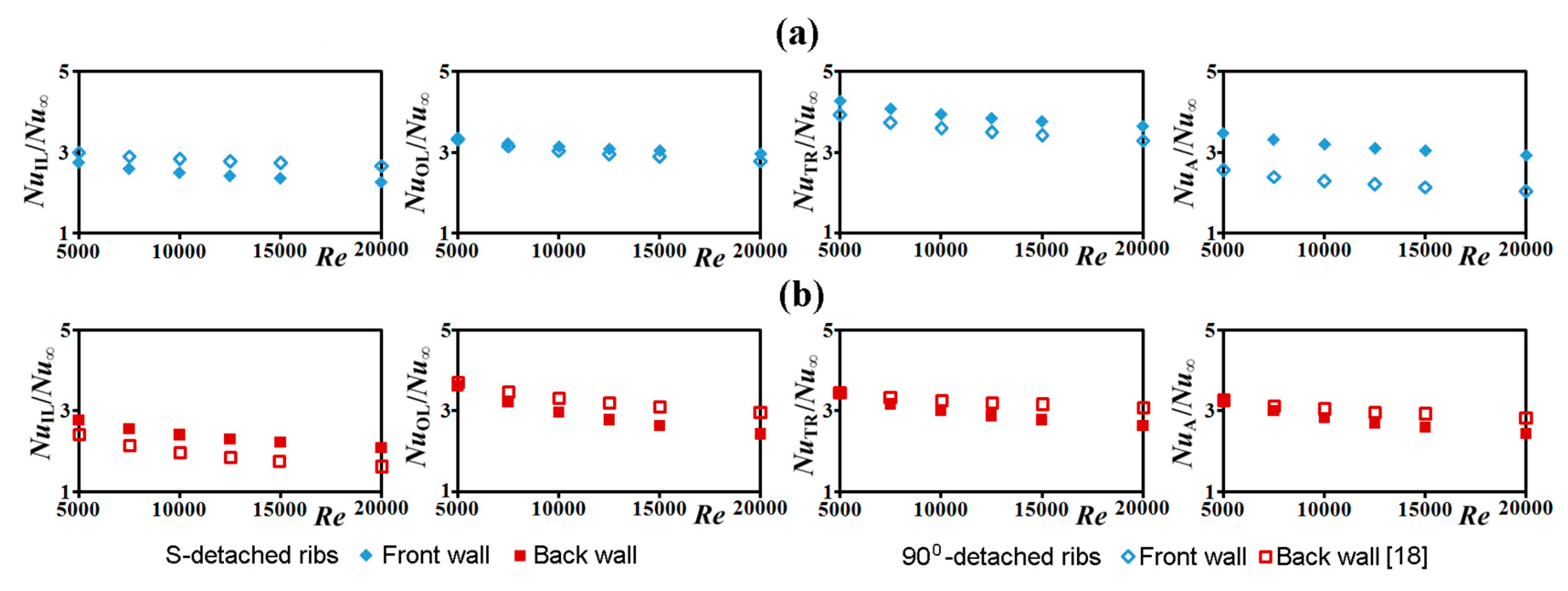
Figure 3 depicts the variations of NuIL/Nu∞, NuTR/Nu∞, NuOL/Nu∞, and NuA/Nu∞ against the Reynolds number for (a) front (b) back endwalls of the twin-pass parallelogram channels with the present S-ribs and the detached 90° ribs [18].
For the twin-pass parallelogram channels with the detached 90° ribs [18] and the present S-ribs, all the NuIL/Nu∞, NuTR/Nu∞, NuOL/Nu∞, and NuA/Nu∞ ratios evaluated from their front walls are higher than the back wall counterparts. As the Reynolds number increases, all the NuIL/Nu∞, NuTR/Nu∞, NuOL/Nu∞, and NuA/Nu∞ ratios collected in Figure 3 are decreased. Similar to the most of passive HTE devices, the heat transfer augmentations are systematically weakened as the Reynolds number increases. As compared by each plot in Figure 3a for the front endwalls, the NuTR/Nu∞, NuOL/Nu∞, and NuA/Nu∞ ratios for the present twin-pass channel with the detached S-ribs are higher than those detected from the similar parallelogram channel with the detached 90° ribs [18]. However, the front-wall NuIL/Nu∞ ratios for the twin-pass parallelogram channel with the detached 90° ribs [18] are higher than the S-rib counterparts as compared in Figure 3a. For the back walls of the twin-pass parallelogram channels, the NuTR/Nu∞, NuOL/Nu∞, and NuA/Nu∞ ratios raised by the detached S-ribs are less than those elevated by the detached 90° ribs [18]; while the NuIL/Nu∞ ratios induced by the S-ribs are higher than the 90°-rib counterparts in Figure 3b. At 5000 ≤ Re ≤ 20,000, the ratios of NuIL/Nu∞, NuTR/Nu∞, NuOL/Nu∞, and NuA/Nu∞ measured from the front and back endwalls of the present twin-pass parallelogram channel with the S-ribs are collected in Table 1.
The quantitative assessment for the front-to-back heat transfer disparities are disclosed by Figure 4, in which the normalized front-to-back Nusselt number differences are compared between the twin-pass parallelogram channels with the detached S- and 90° ribs [18]. The Nusselt number differences between the front and back endwalls in terms of (Nu)front-wall − (Nu)back-wall are normalized as the of the averaged Nusselt numbers defined as [(Nu)front-wall + (Nu)back-wall]/2 for the inlet leg, turning region, outlet leg, and entire endwall area of the twin-pass channels with the detached S- and 90° ribs [18]. For the present test channel with the S-ribs, the front-to-back heat transfer disparities increase consistently by increasing the Reynolds number as disclosed by Figure 4a. With the detached 90° ribs in the twin-pass parallelogram channel [18], the front-to-back heat transfer differences for the outlet leg decrease as the Reynolds number increases in Figure 4b, leading to the moderated overall increase of the front-to-back heat transfer difference for the entire endwall area. At a Reynolds number of 20,000, such front-to-back heat transfer differences for both the twin-pass parallelogram channels with the present detached S-ribs and the detached 90° ribs [18] are similar. Following the two data trends depicted by Figure 4a,b, the higher front-to-back heat transfer differences are expected at Re > 20,000 for the present test channel with the detached S-ribs. Thus, the present detached S-ribs are more suitable for the applications requiring high front-to-back heat transfer differences with high a Reynolds numbers.
Following the power law used by the Dittus–Boelter correlation, the regionally averaged Nusselt numbers over the inlet leg, turning region, outlet leg, and entire endwall for the present test channel with the detached S-ribs are correlated into the empirical equations taking the general structure of
NuIL,TR,OL,A = A × ReB
The correlative coefficients A and B in Equation (6) for inlet leg, turning region, outlet leg, and entire endwall of the front and back endwalls of the present twin-pass parallelogram channel with the detached S-ribs are collected in Table 2. The correlative coefficients of these empirical equations are between 0.96–0.98.
In Table 2, the exponents of Reynolds number, B values, in the NuIL, NuTR, NuOL, and NuA correlations for the front endwall are consistently higher than their back-wall counterparts. Thus, the impacts of forced convective inertia on the regionally averaged heat transfer properties for the front endwall are larger than those on the back endwall for present test channel with the detached S-ribs.
3.2. Pressure Drop and TPF Measurements
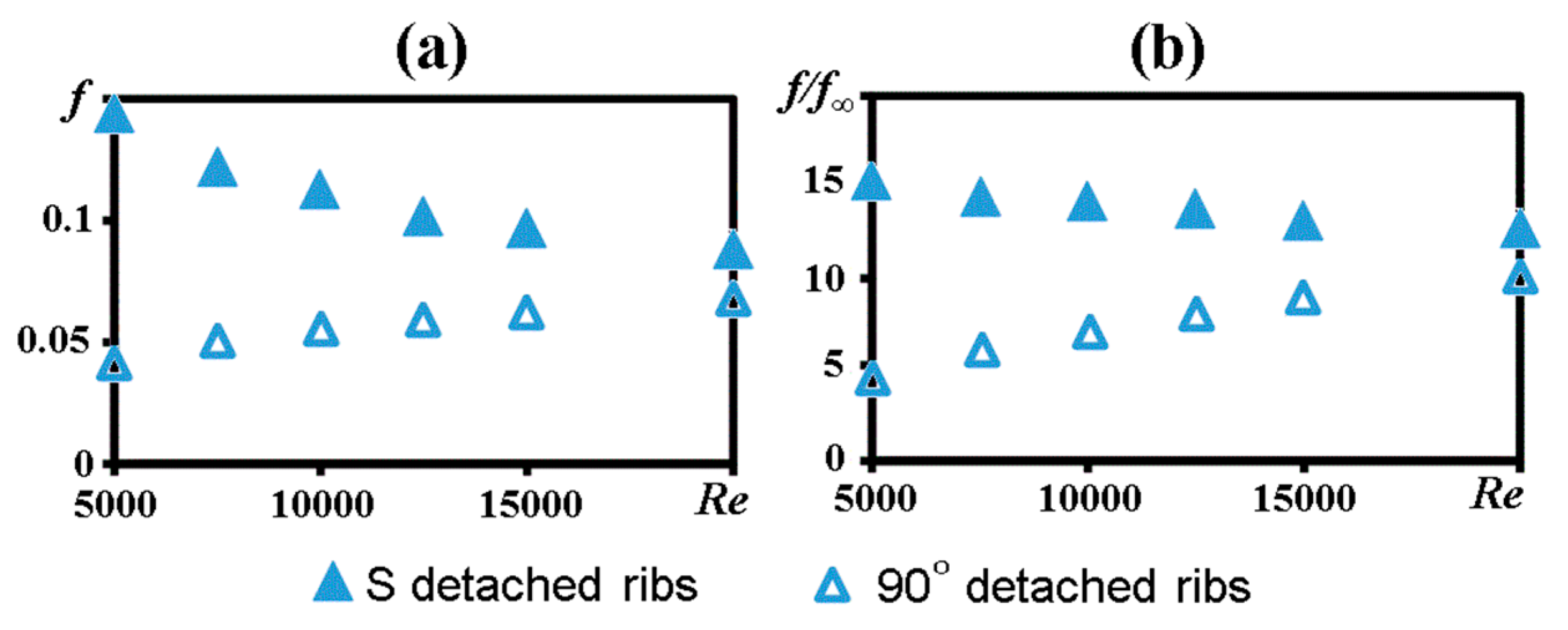
The Fanning friction factors measured from the four channel walls at all the Reynolds numbers tested for the present test channel are averaged as to reflect the overall pressure drop performance in association with the detached S-ribs in the twin-pass parallelogram channel. Figure 5 depicts the variations of (a) (b) /f∞ against the Reynolds number for the present test channel. The and /f∞ data detected from the similar twin-pass parallelogram channel with the detached 90° ribs [18] are also compared in Figure 5. In Figure 5a, the Fanning friction factors detected from the present test channel are consistently higher than those elevated by the detached 90° ribs [18]. But the values for the twin-pass parallelogram channels with the detached S- and 90° ribs [18] are respectively decreased and increased as the Reynolds number increases. In general, the Fanning friction factors attributed to the shearing actions among the fluids tend to decrease with the increase of Reynolds number to follow the typical results of boundary-layer flows. But the pressure drops induced by the changes of flow momentum for ducted flows can lead to the increased Fanning friction factors as Reynolds number increases. For the ribbed twin-pass parallelogram channel [18], the flow momentums are periodically boosted when the airflow traverses the detached 90° ribs near the two opposite endwalls. The Re-driven elevation seen in Figure 5a for the twin-pass parallelogram channel with the detached 90° ribs [18] suggests that the pressure drops due to the rib blockage effects outweigh those caused by frictions. However, for the present test channel, the curly S-ribs prevent the abrupt flow acceleration on each sectional plane. Thus, the rib blockage effects on the augmentations of the Fanning friction factors are moderated from those developed in the similar twin-pass channel with the detached 90° ribs [18]. However, the considerable frictional drags are induced by the present S-ribs to raise the levels from those in the twin-pass parallelogram channel with the detached 90° ribs [18]. The decreased values by increasing Reynolds number in Figure 5a indicate the dominant frictional drags in formulating the f factors for the present test channel.
In view of the normalized /f∞ ratios compared in Figure 5b, the reversing trends of /f∞ ratios against Reynolds number between the twin-pass parallelogram channels with the detached S- and 90° ribs [18] follow the results shown by Figure 5a. With 5000 ≤ Re ≤ 20,000, the ratios of /f∞ for the twin-pass parallelogram channels with the detached 90° ribs [18], and the detached S-ribs are in the respective ranges of 4–10 and 15.1–13. As the Reynolds number increases, the /f∞ ratios for the two twin-pass parallelogram channels with the detached S- and 90° ribs [18] are approaching due to the reversed trends of the Re-driven variations. Based on the data trend depicted in Figure 5a, the Fanning friction factors measured from the present twin-pass parallelogram channel enhanced by the detached S-ribs are correlated as Equation (7) with the correlative coefficient of 0.98.
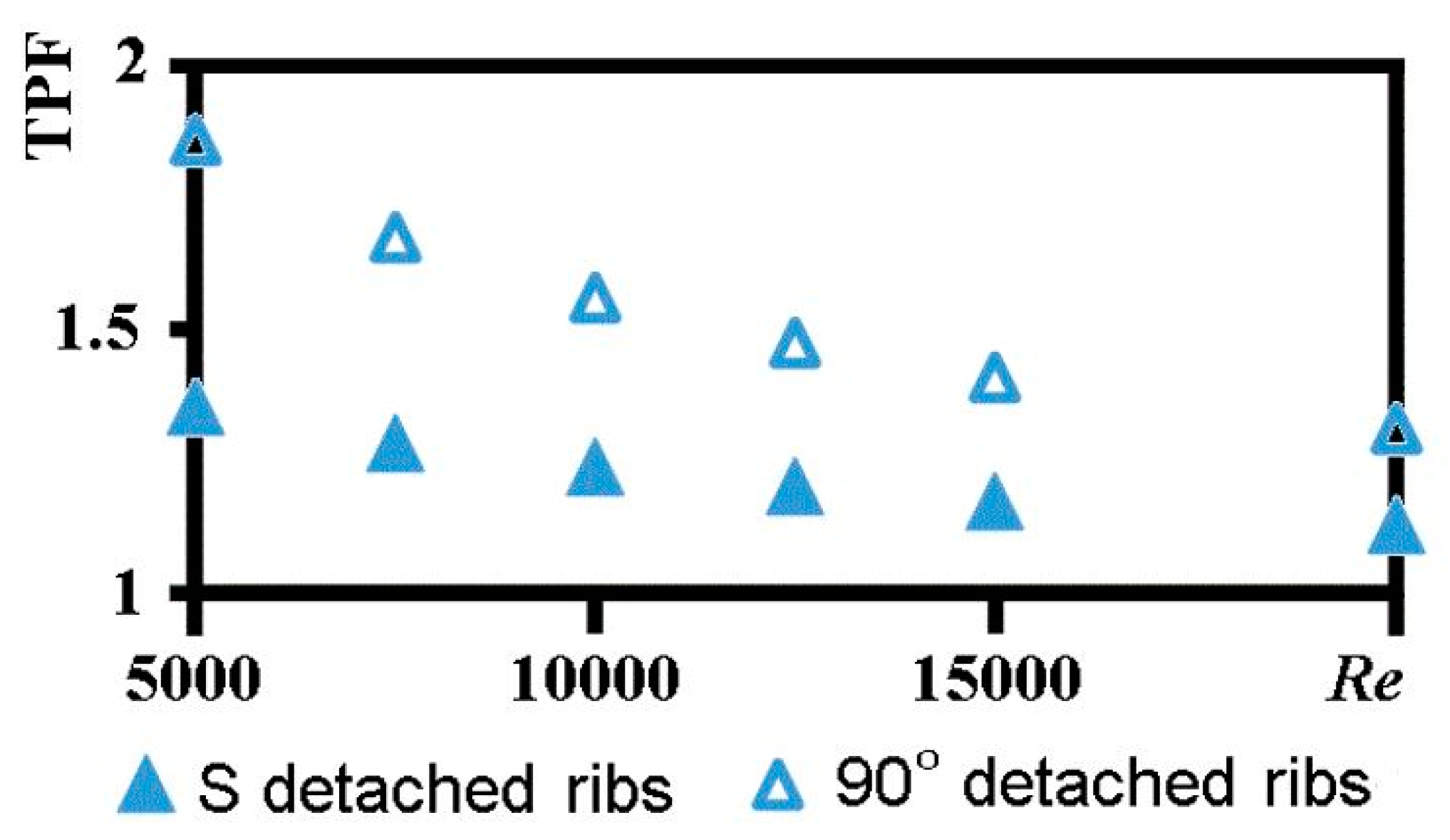
Taking into the account of NuA/Nu∞ ratios between 3.18 and 2.38 for the twin-pass parallelogram channel with the detached 90° ribs [18] and 3.48–2.93 for the present test channel with the detached S-ribs in the Reynolds number range of 5000–20,000, the larger pressure drop augmentations by the detached S-ribs offset the comparative thermo-hydraulic performance of the present HTE element. With the constant pumping power consumptions, the variations of TPF against the Reynolds number for the twin-pass parallelogram channels with the detached S- and 90° ribs [18] are compared in Figure 6.
As compared by Figure 6, the TPF values for the twin-pass parallelogram channels with the detached S- and 90° ribs [18] in the Reynolds number range of 5000–20,000 are all above than unity. Following the typical TPF varying trends for passive heat transfer enhancement devices, the TPF values collected in Figure 6 decrease with the increase of Reynolds number for both twin-pass parallelogram ribbed channels. Such particular TPF reductions by increasing the Reynolds number are inherited from the Re-driven Nu/Nu∞ reductions shown by Figure 3. While the heat transfer enhancements by the present detached S-ribs are elevated from those generated by the detached 90° ribs [18], the larger augmentations of the Fanning friction factors have caused less TPF values for the present test channel with the detached S-ribs as compared in Figure 6. Nevertheless, as all the TPF values are raised from unity by both the detached S- and 90° ribs [18] as demonstrated by Figure 6, both the HTE measurements using the detached S- and 90° ribs in the twin-pass parallelogram channels are efficient from the view point of constant pumping power consumption.
4. Conclusions
With the present detached S-ribs or the detached 90° ribs [18] installed near the opposite endwalls of the twin-pass parallelogram channels, the heat transfer disparities between the front and back endwalls are generated. While the higher heat transfer rates generally emerge on the front endwall, the spanwise Nusselt number decays from the obtuse-corner edge toward the acute-corner edge are developed on both front and back endwalls along the inlet and outlet legs.
The front-to-back heat transfer disparities of the present twin-pass parallelogram channel with the detached S-ribs increase consistently as the Reynolds number increases. The present detached S-ribs are suitable for the high Reynolds number application that prefers the large front-to-back heat transfer differences.
The higher degrees of overall heat transfer augmentation than those induced by the detached 90° ribs are generated by the present detached S-ribs. All the normalized Nu/Nu∞ ratios are decreased as the Reynolds number increases. Due to the flow structure induced by the present detached S-ribs in the twin-pass parallelogram channel, the NuIL/Nu∞, NuTR/Nu∞, NuOL/Nu∞, and NuA/Nu∞ ratios are in the respective ranges of 2.75–2.27, 4.28–3.65, 3.64–3.22, and 3.48–2.93 for the front wall and 2.76–2.09, 3.41–2.63, 3.62–2.42, and 3.18–2.38 for the back wall at 5000 ≤ Re ≤ 20,000.
In contrast to the Re-driven elevation caused by the detached 90° ribs due to the rib blockage effects, the values for the present twin-pass parallelogram channel with the detached S-ribs are decreased as the Reynolds number increases, suggesting that the shearing actions among the fluids dominate the Fanning friction factors. The /f∞ ratios measured from the present test channel are in the range of 15.1–13 with 5000 ≤ Re ≤ 20,000; which are considerably higher than those elevated by the detached 90° ribs in the similar twin-pass parallelogram channel [18].
The TPF values detected at 5000 ≤ Re ≤ 20,000 for the present twin-pass parallelogram channel with the detached S-ribs are all above than unity but decrease with the increase of the Reynolds number. While the higher degrees of heat transfer augmentations are induced by the present detached S-ribs in comparison with those elevated by the detached 90° ribs [18], the larger augmentations by the present detached S-ribs are lesser than the TPF values for the present twin-pass channel.
Two sets of empirical correlations evaluating the regionally averaged Nusselt numbers and the channel averaged Fanning friction factors are devised for the present twin-pass parallelogram channel with the detached S-ribs.
Author Contributions
Conceptualization, S.W.C.; Methodology, S.W.C.; Validation, W.-L.C. and R.-J.W.; Formal Analysis, S.W.C., W.-L.C. and R.-J.W.; Investigation, S.W.C., W.-L.C. and R.-J.W.; Resources, S.W.C.; Data Curation, W.-L.C. and R.-J.W.; Writing-Original Draft Preparation, S.W.C.; Writing-Review & Editing, S.W.C.; Supervision, S.W.C.; Project Administration, W.L.C.; Funding Acquisition, S.W.C.
Funding
This research was funded by Ministry of Science and Technology under the grant number MOST105-2221-E-022-002.
Conflicts of Interest
The authors declare no conflict of interest.
Nomenclature
| English symbols | |
| A:B | Correlative coefficients in heat transfer correlations |
| Cp | Constant pressure specific heat (J·kg−1·K−1) |
| d | Channel hydraulic diameter (m) |
| e | Rib height (m) |
| f | Fanning friction coefficient = [ΔP/(0.5ρWm2)]/(d/4L) |
| f∞ | Blasius equation for turbulent flow = 0.079Re−0.25 |
| G | Clearance between detached rib and channel end wall (m) |
| H | Channel height (m) |
| h | Convective heat transfer coefficient (W·m−2·K−1) |
| L | Channel length (m) |
| l | Rib land (m) |
| Mass flow rate of test coolant (kg·s−1) | |
| Nu | Local Nusselt number |
| P | Rib pitch (m) |
| Ph | Peripheral heating length of test channel (m) |
| ΔP | Pressure difference across entire test channel (N·m−2) |
| qf | Convective heat flux (W·m−2) |
| Re | Reynolds number = ρWmd/μ |
| Tb | Bulk temperature of fluid (K) |
| Tw | Wall temperature (K) |
| TPF | Thermal performance factor = (Nu/Nu∞)/(f/f∞)1/3 |
| W | Channel width (m) |
| Wm | Mean velocity of fluid (m·s−1) |
| x | Spanwise coordinate (m) |
| y | Streamwise coordinate (m) |
| Greek Symbols | |
| λ | Thermal conductivity of fluid (W·m−1·K−1) |
| μ | Fluid dynamic viscosity (kg·m−1·s−1) |
| ρ | Fluid density (kg·m−3) |
| Subscripts | |
| IL | Inlet leg |
| OL | Outlet leg |
| TR | Turning region |
| ∞ | Plain channel developed flow condition |
References
- Chang, S.W.; Liou, T.-M.; Lee, T.-H. Thermal performance of developing flow in a radially rotating parallelogram channel with 45 degrees ribs. Int. J. Therm. Sci. 2012, 52, 186–204. [Google Scholar] [CrossRef]
- Chang, S.W.; Liou, T.-M.; Lee, T.-H. Thermal performance comparison between radially rotating ribbed parallelogram channels with and without dimples. Int. J. Heat Mass Transf. 2012, 55, 3541–3559. [Google Scholar] [CrossRef]
- Liou, T.M.; Chang, S.W.; Yang, C.C.; Lan, Y.A. Thermal performance of a radially rotating twin-pass smooth-walled parallelogram channel. ASME J. Turbomach. 2014, 136, 121007. [Google Scholar] [CrossRef]
- Liou, T.M.; Chang, S.W.; Chan, S.P.; Lin, A. Influence of entrance geometry on flow field and heat transfer performance in stationary twin-pass smooth parallelogram channels. Int. J. Heat Mass Transf. 2017, 105, 549–563. [Google Scholar] [CrossRef]
- Liou, T.-M.; Chen, C.C.; Chen, M.Y. TLCT and LDV measurements of heat transfer and fluid flow in a rotating sharp turning duct. Int. J. Heat Mass Transf. 2001, 44, 1777–1787. [Google Scholar] [CrossRef]
- Liou, T.-M.; Wang, H.; Chan, S.-P. Nusselt number as composite functions of aspect ratio and wall inclination in parallelogram microchannels with three types of thermal boundary conditions. J. Mech. 2017, 33, 521–533. [Google Scholar] [CrossRef]
- Han, J.C.; Park, J.S.; Lei, C.K. Heat Transfer and Pressure Drop on Blade Cooling Channels with Turbulence Promoters; Technical Report; NASA: Washington, DC, USA, 1984.
- Han, J.C.; Park, J.S. Measurement of HEAT TRANSFER and Pressure Drop in Rectangular Channels with Turbulence Promoters; Technical Report; NASA: Washington, DC, USA, 1986.
- Zhao, C.Y.; Tao, W.Q. Effect of rib angle orientation on local mass transfer distribution around sharp 180 deg turn with rib-turbulators mounted in entire twin-pass channels. Heat Mass Transf. 1997, 32, 325–332. [Google Scholar] [CrossRef]
- Mochizuki, S.; Murata, A.; Fukunaga, M. Effects of rib arrangements on pressure drop and heat transfer in a rib-roughened channel with a sharp 180 deg turn. ASME J. Turbomach. 1997, 119, 610–616. [Google Scholar] [CrossRef]
- Ekkad, S.V.; Han, J.C. Detailed heat transfer distributions in twin-pass square channels with rib turbulators. Int. J. Heat Mass Transf. 1997, 40, 2525–2537. [Google Scholar] [CrossRef]
- Ekkad, S.V.; Pamula, G.; Shantiniketanam, M. Detailed heat transfer measurements inside straight and tapered twin-pass channels with rib turbulators. Exp. Therm. Fluid Sci. 2000, 22, 155–163. [Google Scholar] [CrossRef]
- Wang, L.; Sunden, B. Experimental investigation of local heat transfer in a square duct with various-shaped ribs. Heat Mass Transf. 2007, 43, 759–766. [Google Scholar] [CrossRef]
- Egger, C.; von Wolfersdorf, J.; Schnieder, M. Heat transfer measurements in an internal cooling system using a transient technique with infrared thermography. ASME J. Turbomach. 2013, 135, 041012. [Google Scholar] [CrossRef]
- Liou, T.M.; Shuy, W.J.; Tsao, Y.H. Effect of rib height and pitch on the thermal performance of a passage disturbed by detached solid ribs. ASME J. Turbomach. 1998, 120, 581–588. [Google Scholar] [CrossRef]
- Tsia, Y.P.; Hwang, J.J. Measurements of heat transfer and fluid flow in a rectangular duct with alternate attached-attached rib-arrays. Int. J. Heat Mass Transf. 1999, 42, 2071–2083. [Google Scholar] [CrossRef]
- Liu, H.; Wang, J. Numerical investigation on synthetical performances of fluid flow and heat transfer of semiattached rib-channels. Int. J. Heat Mass Transf. 2011, 54, 575–583. [Google Scholar] [CrossRef]
- Liou, T.M.; Chang, S.W.; Lan, Y.A.; Chan, S.P.; Liu, Y.S. Heat transfer and flow characteristics of twin-pass parallelogram channels with attached and detached transverse ribs. ASME J. Heat Transf. 2017, 139, 042001. [Google Scholar] [CrossRef]
- Liou, T.M.; Chang, S.W.; Huang, C.Y.; Lan, I.A.; Chan, S.P. Influence of rotating directions on hydro-thermal characteristics of a twin-pass parallelogram channel with detached transverse ribs. ASME J. Heat Transf. 2018, 140, 102004. [Google Scholar] [CrossRef]
- Fiorentino, M.; Starace, G. Numerical investigations on two-phase flow modes in evaporative condensers. Appl. Therm. Eng. 2016, 94, 777–785. [Google Scholar] [CrossRef]
- Starace, G.; Fiorentino, M.; Longo, M.P.; Carluccio, E. A hybrid method for the cross flow compact heat exchangers design. Appl. Therm. Eng. 2017, 111, 1129–1142. [Google Scholar] [CrossRef]
- Fiorentino, M.; Starace, G. The design of countercurrent evaporative condensers with the hybrid method. Appl. Therm. Eng. 2018, 130, 889–898. [Google Scholar] [CrossRef]
- Gee, D.L.; Webb, R.L. Forced convection heat transfer in helically rib-roughened tubes. Int. J. Heat Mass Transf. 1980, 23, 1127–1135. [Google Scholar] [CrossRef]
- Kim, J.H.; Simon, T.W.; Viskanta, R. Journal of heat transfer policy on reporting uncertainties in experimental measurements and results. ASME J. Heat Transf. 1993, 115, 5–6. [Google Scholar] [CrossRef]
- Chang, S.W.; Cai, W.-L.; Shen, H.-D.; Yu, K.-C. Uncoupling Coriolis force and rotating buoyancy effects on full-field heat transfer properties of a rotating channel. J. Vis. Exp. 2018, in press. [Google Scholar]
- Chang, S.W.; Liou, T.-M.; Po, Y. Coriolis and rotating buoyancy effect on detailed heat transfer distributions in a two-pass square channel roughened by 45° ribs at high rotation numbers. Int. J. Heat Mass Transf. 2010, 53, 1349–1363. [Google Scholar] [CrossRef]
- Johnson, B.V.; Wagner, J.H.; Steuber, G.D.; Yeh, F.C. Heat transfer in rotating serpentine passages with trip skewed to the flow. ASME J. Turbomach. 1994, 116, 113–123. [Google Scholar] [CrossRef]
Figure 1.
(a) Experimental facilities: (1) rotary compressor, (2) demudifier, (3) air tank, (4) needle valve, (5) mass flow meter, (6) cylindrical air plenum chamber, (7) and (8) stainless steel heating foils, (9) copper plates, (10) base plate, (11) top plate, (12) sidewall, (13) back wall, (14) front frame, (15) central divider, (16) thermocouple, (17) flow entry and exit flanges, (18) infrared (IR) camera, (19) digital type micromanometer. (b) configurations of S-rib.
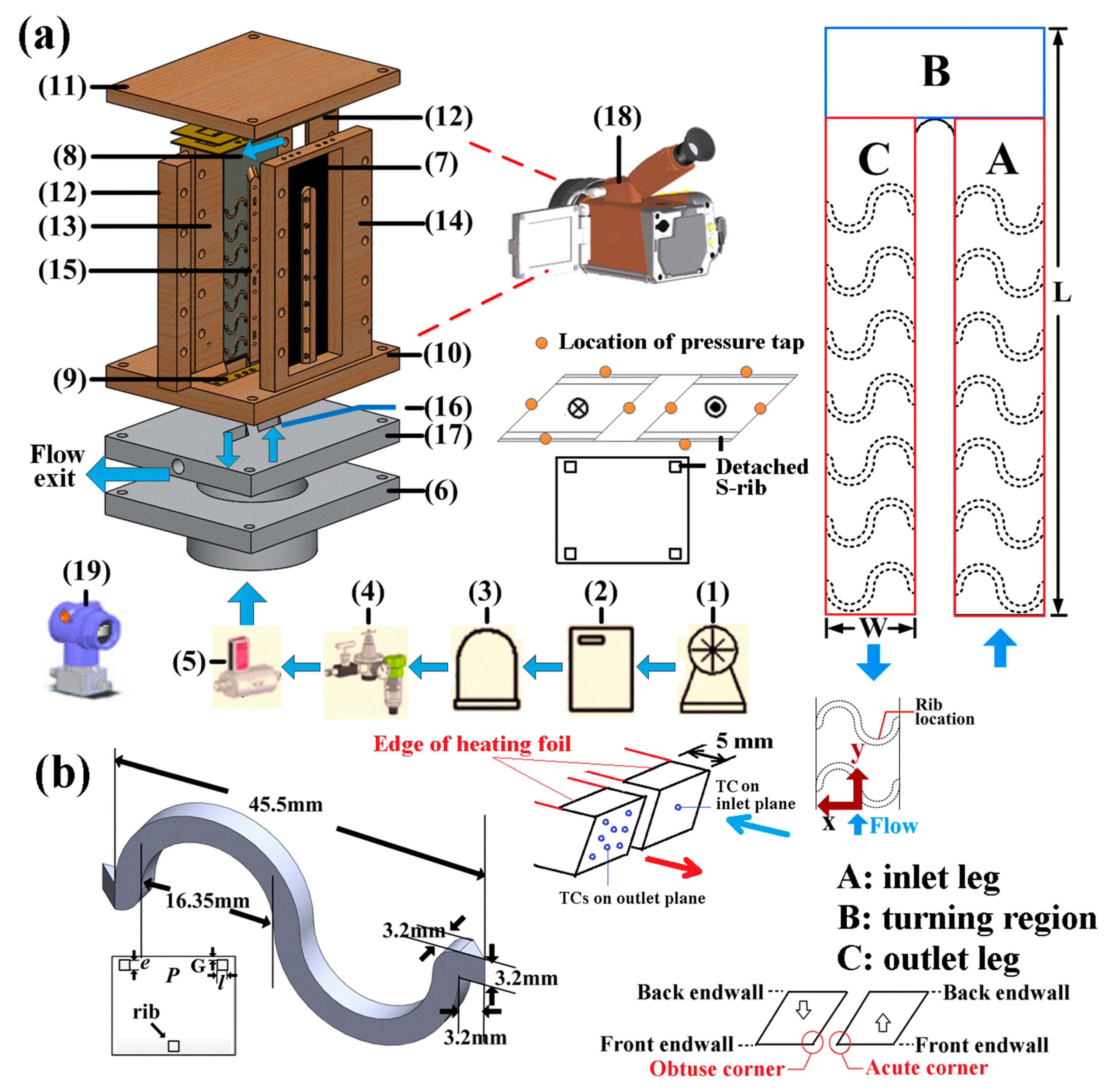
Figure 2.
Detailed Nusselt number distributions on front and back endwalls of the twin-pass parallelogram channels with detached transverse and S-ribs at Reynolds numbers of 5000, 10,000, 15,000. The high Nusselt number regions constantly develop along the endwall edge adjoining the obtuse corners of the parallelogram channels for both front and back endwalls.
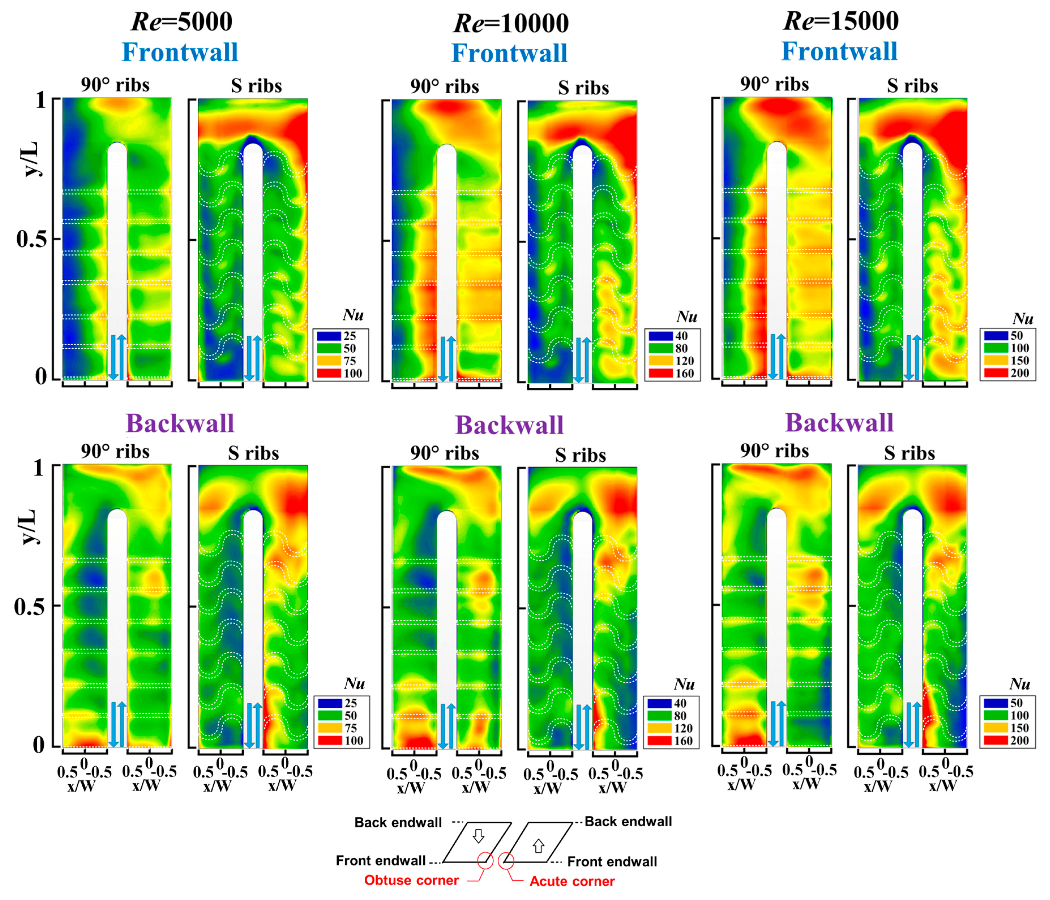
Figure 3.
Variations of NuIL/Nu∞, NuTR/Nu∞, NuOL/Nu∞, and NuA/Nu∞ against Reynolds number for (a) front (b) back endwalls of twin-pass parallelogram channels with detached S-ribs and 90° ribs [18].
Figure 3.
Variations of NuIL/Nu∞, NuTR/Nu∞, NuOL/Nu∞, and NuA/Nu∞ against Reynolds number for (a) front (b) back endwalls of twin-pass parallelogram channels with detached S-ribs and 90° ribs [18].

Figure 4.
Normalized Nusselt number difference ratios for highlighting heat transfer disparities between front and back endwalls of twin-pass parallelogram channels with detached S-ribs and 90° ribs [18].
Figure 4.
Normalized Nusselt number difference ratios for highlighting heat transfer disparities between front and back endwalls of twin-pass parallelogram channels with detached S-ribs and 90° ribs [18].
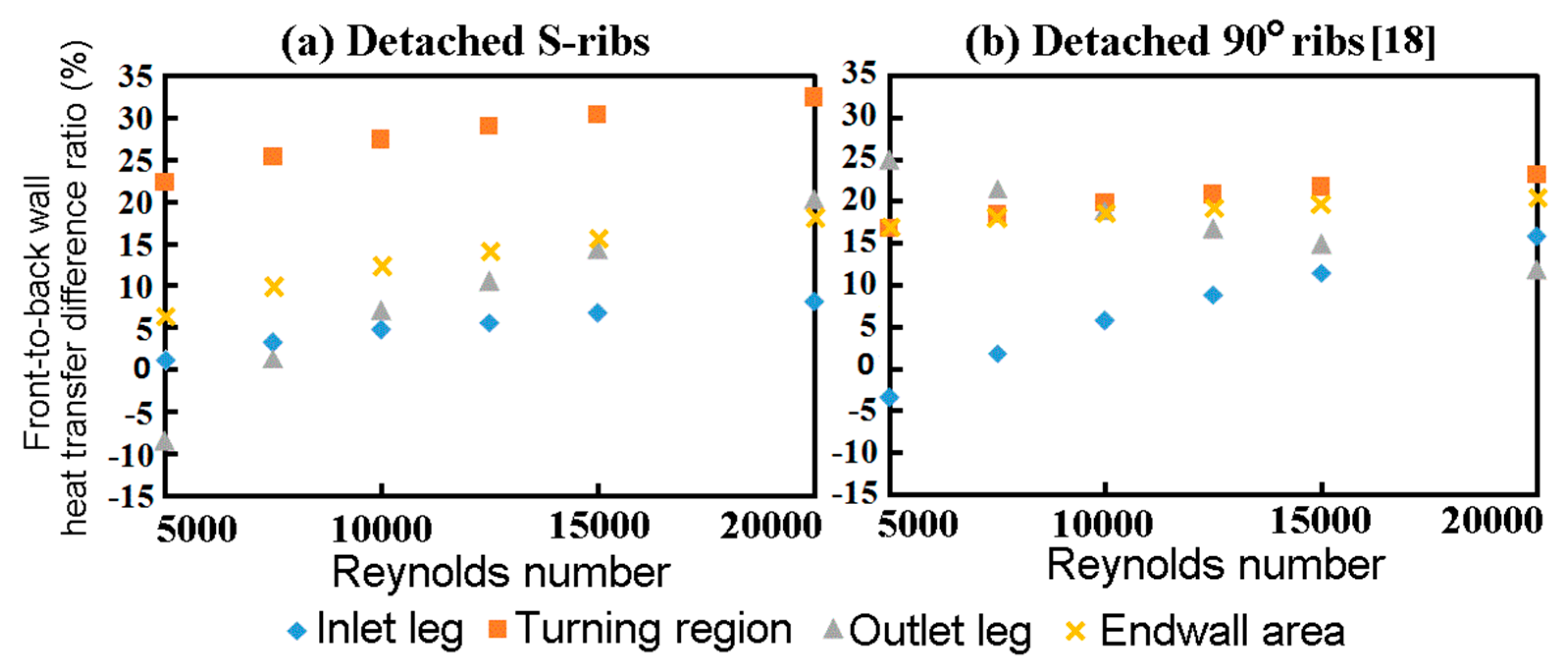
Figure 5.
Variations of (a) (b) /f∞ against the Reynolds number for the twin-pass parallelogram channels with detached S-ribs and 90° ribs [18].
Figure 5.
Variations of (a) (b) /f∞ against the Reynolds number for the twin-pass parallelogram channels with detached S-ribs and 90° ribs [18].

Figure 6.
Variations of thermal performance factors (TPF) against the Reynolds number for the twin-pass parallelogram channels with detached S-ribs and 90° ribs [18].
Figure 6.
Variations of thermal performance factors (TPF) against the Reynolds number for the twin-pass parallelogram channels with detached S-ribs and 90° ribs [18].


Table 1.
Heat transfer enhancements of front and back endwalls of the present twin-pass parallelogram channel with detached S-ribs.
Table 1.
Heat transfer enhancements of front and back endwalls of the present twin-pass parallelogram channel with detached S-ribs.
| NuIL/Nu∞ | NuTR/Nu∞ | NuOL/Nu∞ | NuA/Nu∞ | |
|---|---|---|---|---|
| Front wall | 2.75–2.27 | 4.28–3.65 | 3.64–3.22 | 3.48–2.93 |
| Back wall | 2.76–2.09 | 3.41–2.63 | 3.62–2.42 | 3.18–2.38 |
Table 2.
Coefficients A and exponents B in heat transfer correlations.
| Endwall Region | Front Endwall | Back Endwall | ||
|---|---|---|---|---|
| A | B | A | B | |
| Inlet leg | 0.178 | 0.662 | 0.309 | 0.598 |
| Turning region | 0.228 | 0.685 | 0.342 | 0.611 |
| Outlet leg | 0.154 | 0.712 | 0.849 | 0.511 |
| Entire endwall | 0.202 | 0.675 | 0.378 | 0.591 |
© 2018 by the authors. Licensee MDPI, Basel, Switzerland. This article is an open access article distributed under the terms and conditions of the Creative Commons Attribution (CC BY) license (http://creativecommons.org/licenses/by/4.0/).
Share and Cite
MDPI and ACS Style
Chang, S.W.; Cai, W.-L.; Wu, R.-J. Heat Transfer Enhancement by Detached S-Ribs for Twin-Pass Parallelogram Channel. Inventions 2018, 3, 50. https://doi.org/10.3390/inventions3030050
AMA Style
Chang SW, Cai W-L, Wu R-J. Heat Transfer Enhancement by Detached S-Ribs for Twin-Pass Parallelogram Channel. Inventions. 2018; 3(3):50. https://doi.org/10.3390/inventions3030050
Chicago/Turabian StyleChang, Shyy Woei, Wei-Ling Cai, and Ruei-Jhe Wu. 2018. "Heat Transfer Enhancement by Detached S-Ribs for Twin-Pass Parallelogram Channel" Inventions 3, no. 3: 50. https://doi.org/10.3390/inventions3030050