Article

Characteristics and Performance of CAUTO (CAssino hUmanoid TOrso) Prototype

Laboratory of Robotics and Mechatronics (LARM), DICEM, University of Cassino and South Latium, 03043 Cassino, Italy
*
Author to whom correspondence should be addressed.
Inventions 2017, 2(3), 17; https://doi.org/10.3390/inventions2030017
Submission received: 23 June 2017 / Revised: 28 July 2017 / Accepted: 9 August 2017 / Published: 15 August 2017
(This article belongs to the Special Issue Advances in Mechanism Design for Robots)

Abstract

:
An artificial torso is a fundamental part of a humanoid robot for imitating human actions. In this paper, a prototype of CAUTO (CAssino hUmanoid TOrso) is presented. Its design is characterized by artificial vertebras actuated by cable-driven parallel manipulators. The design was conceived by looking at the complex system and functioning of the human torso, in order to develop a solution for basic human-like behavior. The requirements and kinematic structure are introduced to explain the peculiarities of the proposed mechanical design. A prototype is presented, and built with low-cost and high-performance features. Tests results are reported to show the feasibility and the characteristics in replicating human torso motions. In addition, the power consumption has been measured during the tests to prove the efficiency of the Li-Po battery supply, employed for a fully portable solution of the designed torso.

Graphical Abstract

1. Introduction

Humanoid robots are designed to replicate human structure and human behavior for several applications or even for humans assistance [1]. In the last few decades, technological developments have permitted the investigation and construction of humanoid robots with advanced capabilities in mobility and actions that can be used in typical human operations in daily life and human environments. Significant examples of such inventions include ASIMO by Honda [2], Wabian by Waseda University [3], HRP by AIST-KAWADA [4], LOLA by Technical University of Munich, and HUBO by KAIS [5].
Drawing inspiration from the human body is necessary to consider the mechanisms of structures that can be identified in the muscular-exoskeleton system as combination of serial and parallel chains. In general, the bone structure can be considered as a serial kinematic chain that is actuated by the parallel architectures of the muscles [6]. In particular, the torso is the central structure in the human body that is well characterized by such an integrated design of a serial-chain bone structure (the spine) with a parallel-chain muscular system. The CAssino hUmanoid TOrso (CAUTO) design was conceived as a conceptual replica of a serial-chain spine cooperating with a cable-driven parallel-chain actuating system with the aim to integrate the advantages of both mechanism topologies but to limit their disadvantages by reciprocal compensation. Tendon-driven humanoid structures have also been proposed, such as the Kenta humanoid [7] and neck design [8], which draw inspiration from the muscular skeleton of human anatomy.
It is well known that serial chains show large workspace mobility but suffer from low load capability, limited motion precision, and vibration disturbances [9]. On the other hand, parallel chains demonstrate better performance in payload, stiffness, and dynamic motion, although they exhibit a small workspace and have a complex direct kinematics formulation.
This is why, in existing humanoid robots, the torso is usually designed using one of the two aforementioned structures, limiting the mobility to few DOFs (Degrees Of Freedom) for basic movements.
In this paper, a successful design combining serial- and parallel-chain mechanisms is presented for a new humanoid torso. The proposed design is explained also in terms of performance evaluation through experimental results for a characterization of the built prototype.

2. The CAssino hUmanoid TOrso (CAUTO) Design

The design of a humanoid torso refers to the anatomy and capability of a human torso that is composed of a complex muscular-skeleton structure [10,11]. The important role of a torso can be summarized as central platform of a body both for organ storage and motion/payload capability. Such a role is also fundamental in humanoid robots, where the structure and operation of a humanoid torso is conceived with human-like features, but with reduced complexity and capability. The design of the CAssino hUmanoid TOrso called CAUTO was conceived with the peculiarity of having a central spine-like structure that is actuated by a suitable cable-driven parallel architecture, aiming to mimic human anatomy and its high performance.

2.1. Kinematic Design and Requirements

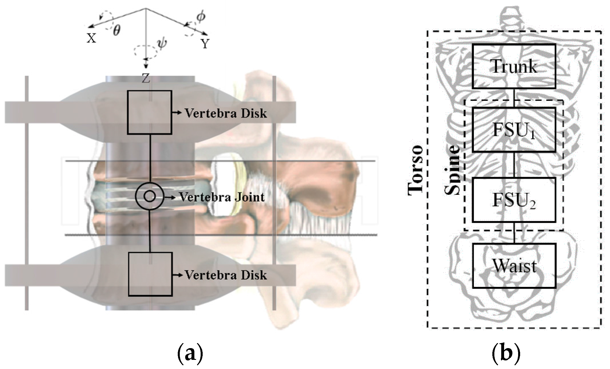
The main requirements for a humanoid torso can be identified in motion suitable ranges and payload capability. The motion requirements refer to bending and torsion movements that are necessary both for the stability of the whole humanoid body and the performance of the manipulation and locomotion tasks. Those requirements can be fulfilled with a specific structure system of the torso, such as a combination of a shoulder body with a waist platform that are connected by an artificial spine, similar to human anatomy. This is the conceptual design for the development of CAUTO, as reported in References [12,13,14,15]. The kinematic design is sketched in Figure 1, in which the artificial spine is composed of four vertebral discs that are connected to each other by a spherical articulation with flexible motion for the three rotations in θ, Φ, and ψ around the XYZ frame axes. The shoulder body is connected to the artificial spine through vertebra disc 4, and the waist body includes vertebral disc 1. Within the waist body, five actuators are installed to provide the actuation of the three actuated DOFs of the artificial spine. The two actuated DOFs for bending are obtained by the actuation of four cables working two-by-two in an antagonist way when actuated by one motor each. The two bending motions in sagittal and lateral planes can be performed separately or in a combined motion. The kinematics of those motions were solved by looking at each planar motion as reported in Reference [16], with a fairly simple formulation for practical and efficient operation.
The torsion motion is obtained by the fifth actuator that generates the torsion rotation of the upper part of the torso with respect to the waist.

2.2. Mechanical Design

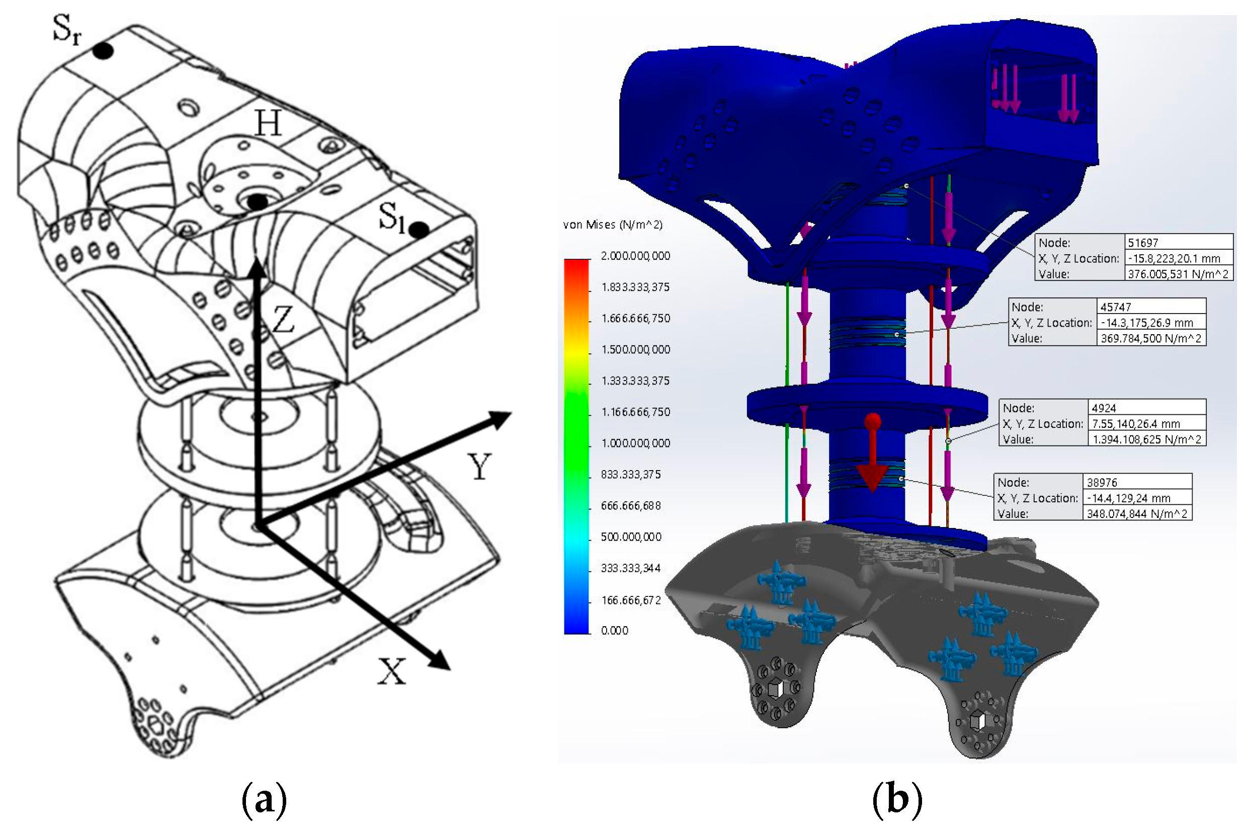
The mechanical design of CAUTO was based on the concept of the FSU (Functional Spine Unit), which models the functionality and structure of the spine through the basic components for mobility and payload capability as two vertebrae connected by an articulation. An representative FSU of the CAssino hUmanoid TOrso design is shown in Figure 2a. The mechanical conceptual design of CAUTO is represented in Figure 2b as obtained by the combination of two FSUs only. The mechanical design was developed in the CAD solution, shown in Figure 3a, that was subsequently used in further design simulations [16,17]. As seen in Figure 3a, the shoulder body was designed, including vertebral disc 4 within it, and the overall shape was conceived to provide room for sensor storage and for the connection of an artificial arm to the shoulder plate. Similarly, the waist body was shaped to host the actuators and to permit the connection of artificial legs. Simulations were worked out for the dynamic operation, as reported in Reference [16]. FEM simulations were used to properly size the parts and to check the feasibility of the chosen material [17]. The results shown in Figure 3b show the stress computations with feasible values that confirm the mechanical stifness of the design with 3D-printed parts together with commercial components. In particular, for the FEM computations as well as for the dynamic simulations, the following data were assumed: actuator torque of 1.27 Nm; cables were made of steel, vertebral articulations were made of aluminum alloy, and body parts were made of ABS plastic.
The FEM computations gave stress values, as indicated in significant points in Figure 3b, that verify the feasibility as well as the stiffness of the designed structure in all its components.

3. The Low-Cost Prototype

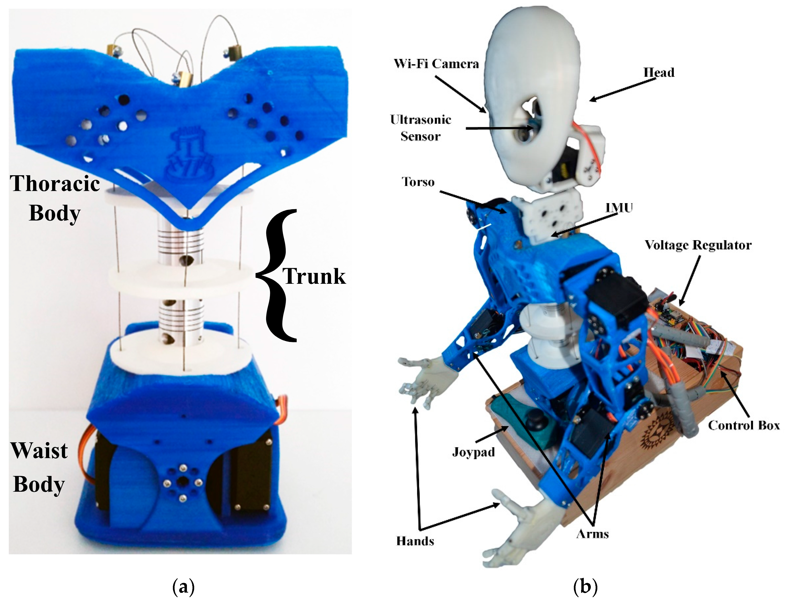
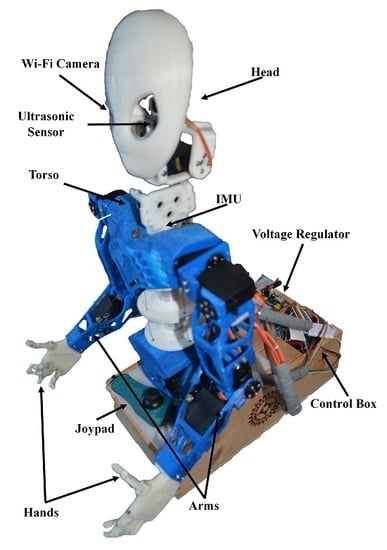
A prototype was built at LARM in Cassino by looking for a low-cost solution using 3D-printing manufacturing for structural parts and commercial components for actuators, sensors, and connections. The prototype is shown in Figure 4. The prototype of the torso alone in Figure 4a can fit into a box with dimensions of 154.00 mm × 113.80 mm × 261.34 mm. The waist is thicker than the shoulder body; it is sized within the dimensions of 116.00 mm × 113.80 mm × 105.19 mm. The trunk, consisting of the torso part between the thoracic and waits parts, is sized within the dimensions of 154.00 mm × 94.50 mm × 81.90 mm. The weight of only the torso structure is 1.2 kg, including all its components and systems. It has also been assembled in a humanoid version, with arms and head, as shown in Figure 4b. With the fully extended arms, it can fit in a box with dimensions of 307.00 mm × 113.80 mm × 538.60 mm, with a weight of 1.6 kg. The humanoid assembly is characterized by anthropomorphic arms and a head that is equipped with sensors for vision, the purpose of which is to verify its practical feasibility in humanoid tasks.
The CAD design in Figure 3a was used to define the structural parts that were manufactured by 3D-printing at LARM, namely the shoulder platform, the waist body, the head, and the anthropomorphic arms. The procedure in Reference [18] was used for this construction, with the aim of achieving a fairly simple design and low-cost products. During the manufacturing, a further optimization was worked out by properly choosing two different kinds of plastic. PLA was chosen as the printing material for the waist and the trunk parts since it has a better stiffness between each layer, so that the trunk will successfully transmit the motion and the waist will afford the payload. On the other hand, ABS was chosen for the discs, since it shows better mechanical properties than PLA as per impact resistance.
Commercial components were selected as solutions for all the other components, namely the actuators, the sensors, the cables, the battery, and the flexible vertebra articulations, in order to achieve a low-cost prototype with fairly easy component replacement. In particular, the spherical vertebra articulations were obtained by using Huco Single Helix Beam Couplings [19], which are made of light aluminum alloy. TowerPro MG995 servomotors [20] were used to actuate the steel cables to move the spine. An Inertial Measurement Unit (IMU) sensor made by a triple-axes accelerometer, gyroscope, and magnetometer [21,22,23] was installed on the top of the spine to monitor the motion in terms of angular displacement and acceleration, as well as for control purposes. An ACS712 Hall sensor module [24] was used to acquire the current to measure the power consumption during the validation tests. Within the head frame, vision sensors such as an ultrasonic sensor [25] and WiFi Camera [26] were installed to give vision capability both to know the surrounding environment and to control the overall motion. The full prototype of Figure 4b was used to check the feasibility of the torso in Figure 4a for implementation in humanoid designs.

4. Experimental Tests for Performance Evaluation

The built prototype in Figure 4 was used for testing the performance characteristics and to check the feasibility of the design and its operation in humanoid tasks [27]. Several tests were carried out at LARM to characterize the performance operation in motion, payload carrying, and lifting capability. In this paper, tests results are reported for two different configurations, namely the torso only and the humanoid assembly with arms and a head, in order to show an experimental characterization.

4.1. Torso Behaviour in Bending

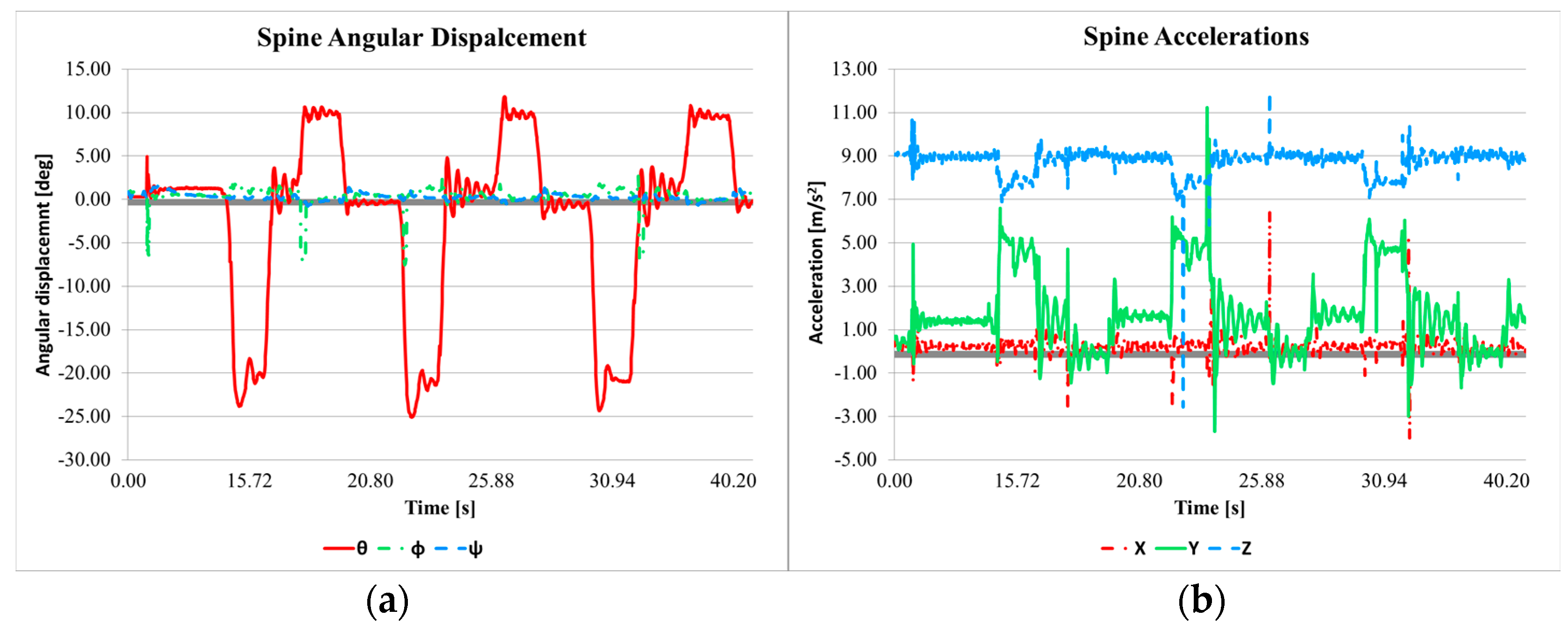
The torso behavior was tested in terms of motion ranges and payload capability. Tests were run with and without the arms and head, by moving only the torso. In Figure 5, a sequence of test configurations is shown for the case of successful torso bending with a payload on the back of 1.150 kg. Results of the test are shown in Figure 6 and Figure 7.
Figure 6a shows the angles that were acquired by the IMU during the bag carrying experiment lasting in 40.20 s with three repeated movements. The plot reports a first calibration phase from 0.00 s to 10.85 s, the homing of the servomotors, and the three repetitions of the bending motion. The acquired angles θ are within the range between −25.08° and 11.68°; the angle Φ is within the range between −7.57° and 2.70°; and the angle ψ is within the range between −0.77° and 1.63°. The main bending rotation is performed around the X-axis and it is 36.76°, and replicates human motion quite satisfactorily, even in terms of velocity and acceleration. In the plot, the forward and backward movements can be identified clearly by the phases with positive and negative values with major bending in forward configurations.
In addition, the angular displacement exhibits a relationship with the linear acceleration, as shown in in Figure 6b, both of which are measured for the point at the top of the spine. When the torso bends forward from 14.58 s up to 16.70 s, the IMU senses the two components of the acceleration along the Y-axis and Z-axis. The measured acceleration along the Y-axis has a range between −4.00 and 6.39 m/s2. The acceleration component along the Z-axis with a range between −2.55 and 9.81 m/s2. The Z-axis has a zero offset of 9.81 that is due to the acceleration of gravity. The acceleration along the X-axis is negligible. Vibration noise is detected as coming both from the motor motion and the prototype mechanical design.
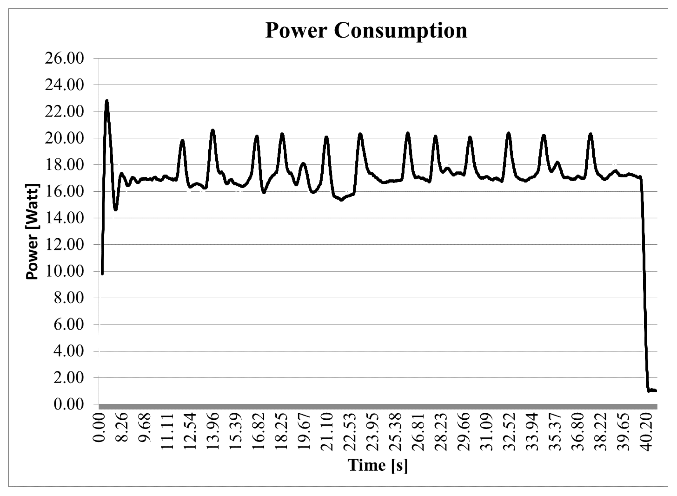
Figure 7 shows the power consumption during the experiment in Figure 5. Each bending movement can be easily recognized in the time evolution in the plot with the power peaks characterizing the start and end of a bending movement. Two phases can be seen in the plot for each bending movement of the three repeated forward-backward motions. For each motion, the actions are identified by two peak couples that represent the power needed to go forward, go back to the starting point, and then go backward. The power consumption during the experiment, without taking into consideration the powering on phase, has a range between 0.17 and 21.42 W with a mean value of 16.95 W.
The above results of the experiment show that the proposed torso can lift a bag containing its own weight with no problems, achieving a satisfactory humanoid behavior with acceptable movement range and acceleration, thanks to the contribution of the commercial servomotors. Furthermore, the limited power consumption of the system allows the usage of a battery as a power supply with good durability.

4.2. Torso Behaviour in Lifting Loads

The humanoid assembly with the arms was tested in terms of motion ranges and payload capability. Tests were run by in lifting a payload using the arms with a compensation motion performed by the torso. Tests were carried out with the humanoid assembly of Figure 8 both to check the feasibility of the torso for a humanoid implementation and to investigate the effects of the arms and head structure on the torso performance. In Figure 8, a sequence of test configurations is shown for the case of successful payload lifting by the arms with a small torso bending for a payload of 0.560 kg. The payload was reduced with respect to the previous case for torso capability, since the arms imposed a reduction of payload capability due to their mechanical design. Results of the test are shown in Figure 9 and Figure 10.
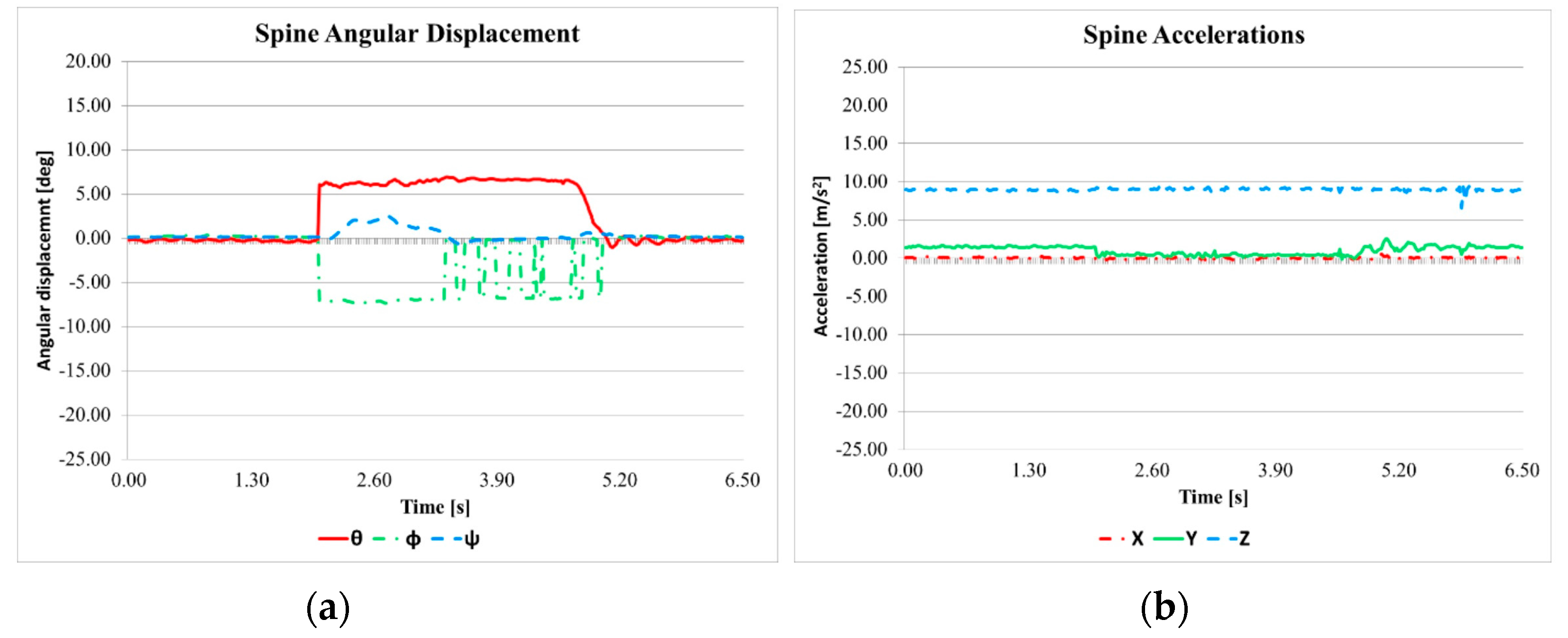
Figure 9a shows the angles that were acquired by the IMU during the arm payload lifting experiment lasting 40.20 s. The test was executed in three movements, namely load lifting in 7.60 s, stationary configuration for 8.44 s, and going back to home position. When the arms are lifting the load, the torso needs to bend to compensate the change of the position of the center of gravity of the humanoid assembly. The main motion of the torso is along the X-axis, and the acquired angles θ range between −3.76° and 0.23°; the angle Φ is within the range between −2.44° and 2.37°, and the angle ψ is within the range between −32.07° and 3.68°. The arms are actuated by moving the elbow joints to lift the load. In addition, the angular displacement exhibits a relationship with the linear acceleration shown in Figure 9b, both of which are measured for the point at the top of the spine. The torso acceleration is small so as to ensure a smooth motion, and it is measured along the X-axis with a range between −2.24 and 2.20 m/s2, along the Y-axis with a range between −0.24 and 2.55 m/s2, and along the Z-axis with a range between 8.16 and 9.81 m/s2. Small vibration noise is detected again at the moment of the changes of the motions.
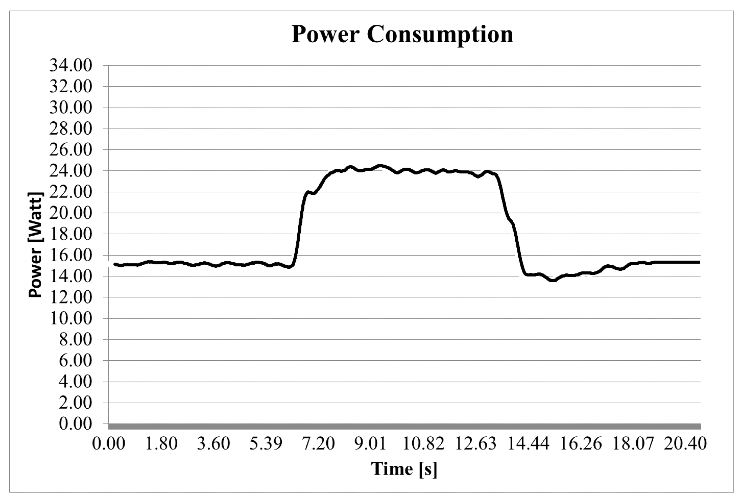
Figure 10 shows the power consumption during the experiment in Figure 8. The measured power consumption is quite constant at the maximum value during the time of the stationary configuration with the lifted payload. Changes of the power consumption are detected at the beginning of the lifting and at the return to the home configuration. However, power is needed to maintain the humanoid assembly in operation, even when it is not moving. The power consumption during the experiment, without taking into consideration the powering on phase, has a range between 13.32 and 24.09 W with a mean value of 18.07 W.
The above results of the experiments show that the proposed torso with a humanoid assembly can lift a payload by supporting the actions of arms with a satisfactory humanoid behavior and acceptable movement range and accelerations, with some limitation of the action due to the arm structure. However, the limited power consumption of the humanoid assembly confirms the efficiency of the torso design for the usage of a battery as a power supply in a humanoid design.

5. Conclusions

This paper presents a prototype of CAUTO (CAssino hUmanoid Torso) with its peculiar biomimetic design and high-performance characteristics. The kinematic design is characterized by a spine-like structure that is actuated by cable-driven parallel manipulators, so that the torso can perform human-like motions with high payload capability. Results of experimental validation show that the torso is capable of carrying a load larger than its own weight, but that the weight capability is reduced when the torso is equipped with arms. The compact design has been transferred to a prototype that has been built using 3D-printing manufactured parts, assembled together with properly selected commercial components. The presented prototype has low energy consumption and can store batteries for an autonomous portable solution in humanoid structures. Thus, this paper provides evidence of the good performance of the prototype in experimental tests, indicating both a validation of the CAUTO design with low-cost features and its characterization with high payload capability.

Author Contributions

Daniele Cafolla carried out the characterization of the human torso behaviour to get inspiration and propose a final version of the prototype that he has been developed going through the design, the construction, the control and the experimental validation; Marco Ceccarelli has helped and supervised during the work discussing and introducing problems for design and operation of solutions for a humanoid torso. He took place also in the characterization and evaluation of the performance of the prototype analysing the test results together with Daniele Cafolla.

Conflicts of Interest

The authors declare no conflict of interest.

References

  1. Kemp, C.; Fitzpatrick, P.; Hirukawa, H.; Yokoi, K.; Harada, K.; Matsumoto, Y. Humanoid Robots. In Springer Handbook of Robotics; Siciliano, B., Khatib, O., Eds.; Springer: Berlin/Heidelberg, Germany, 2008; pp. 1307–1333. [Google Scholar]
  2. Hirose, M.; Ogawa, K. Honda humanoid robots development. Philos. Trans. R. Soc. 2007, 365, 11–19. [Google Scholar] [CrossRef] [PubMed]
  3. Ogura, Y.; Aikawa, H.; Shimomura, K.; Morishima, A.; Lim, H.O.; Takanishi, A. Development of a new humanoid robot WABIAN-2. In Proceedings of the ICRA 2006, 2006 IEEE International on Robotics and Automation, Orlando, FL, USA, 15–19 May 2006; pp. 76–81. [Google Scholar]
  4. Kaneko, K.; Kanehiro, F.; Morisawa, M.; Miura, K.; Nakaoka, S.; Kajita, S. Cybernetic Human HRP-4C. In Proceedings of the 9th IEEE/RAS International Conference on Humanoid Robots (Humanoids 2009), Paris, France, 7–10 December 2009; pp. 7–14. [Google Scholar]
  5. Zucker, M.; Joo, S.; Grey, M.X.; Rasmussen, C.; Huang, E.; Stilman, M.; Bobick, A. A General-purpose System for Teleoperation of the DRC-HUBO Humanoid Robot. J. Field Robot. 2015, 32, 336–351. [Google Scholar] [CrossRef]
  6. Mizuuchi, I.; Tajima, R.; Yoshikai, T.; Sato, D.; Nagashima, K.; Inaba, M.; Kuniyoshi, Y.; Inoue, H. The design and control of the flexible spine of a fully tendon-driven humanoid “Kenta”. In Proceedings of the IEEE/RSJ International Conference on Intelligent Robots and Systems, Lausanne, Switzerland, 30 September–4 October 2002; pp. 2527–2532. [Google Scholar]
  7. Nori, F.; Jamone, L.; Sandini, G.; Metta, G. Accurate control of a human-like tendon-driven neck. In Proceedings of the 2007 7th IEEE-RAS International Conference on Humanoid Robots, Pittsburgh, PA, USA, 29 November–1 December 2007; pp. 371–378. [Google Scholar]
  8. Saladin, K.S. Human Anatomy; McGraw Hill Higher Education: New York, NY, USA, 2008. [Google Scholar]
  9. Ceccarelli, M. Fundamentals of Mechanics of Robotic Manipulation; Kluwer/Springer: Dordrecht, The Netherlands, 2004. [Google Scholar]
  10. Huston, R.L. Principle of Biomechanics; CRC Press: Boca Raton, FL, USA, 2009. [Google Scholar]
  11. Virginia, C. Bones and Muscles: An Illustrated Anatomy; Wolf Fly Press: New York, NY, USA, 1999. [Google Scholar]
  12. Cafolla, D.; Ceccarelli, M. Design and simulation of humanoid spine. In New Trends in Mechanism and Machine Science: From Fundamentals to Industrial Applications; Springer: Dordrecht, The Netherlands, 2014; pp. 285–594. [Google Scholar]
  13. Cafolla, D.; Cheng, I.; Ceccarelli, M. An experimental characterization of human torso motion. Front. Mech. Eng. 2015, 10, 311–325. [Google Scholar] [CrossRef]
  14. Cafolla, D.; Ceccarelli, M. Design and validation of a PKM Structure for a Humanoid Torso. In Proceedings of the 14th IFToMM World Congress, Taipei, Taiwan, 25–30 October 2015. paper OS13–122. [Google Scholar]
  15. Cafolla, D.; Ceccarelli, M. Experimental Inspiration and Rapid Prototyping of a novel Humanoid Torso. In Robotics and Mechatronics, Proceedings of the 4th IFToMM International Symposium on Robotics and Mechatronics, Poitiers, France, 23–25 June 2015; Springer: Dordrecht, The Netherlands, 2015; pp. 65–74. [Google Scholar]
  16. Cafolla, D.; Ceccarelli, M. Design and simulation of a cable-driven vertebra-based humanoid torso. Int. J. Hum. Robot. 2016, 13. [Google Scholar] [CrossRef]
  17. Cafolla, D.; Ceccarelli, M. Design and FEM analysis of a novel humanoid torso. In Multibody Mechatronic Systems; Springer: Dordrecht, The Netherlands, 2014; pp. 477–488. [Google Scholar]
  18. Ceccarelli, M.; Carbone, G.; Cafolla, D.; Wang, D.M.F. How to use 3D printing for feasibility check of mechanism design. In Advances in Robot Design and Intelligent Control; Springer International Publishing: Cham, Switzerland, 2015; pp. 307–315. [Google Scholar]
  19. Single Helix Beam Couplings, Flexible Couplings Catalog, Category #59; Huco: Hertford, UK, 2016.
  20. Servo Catalog, #MG995; TowerPro.: Singapore, 2016.
  21. ACS712 Current Sensor, Datasheet, ACS712-DS Rev. 15; Allegro MicroSystems, Inc.: Worcester, MA, USA, 2016.
  22. Digital Accelerometer, Document Number: D07925-0-5/09(0), Product #ADXL345; Analog Devices Inc.: Norwood, MA, USA, 2009.
  23. 3-Axis Gyroscope, Document Number: EB-ITG-3200-00-01.1, Product #ITG-3200; InvenSense: San Jose, CA, USA, 2010.
  24. 3-Axis Digital Compass, Document Number: 900405 Rev D, Product #HMC5883L; Honeywell: Morris Plains, NJ, USA, 2011.
  25. PING)))™ Ultrasonic Distance Sensor, Parallax Catalog #28015; Parallax: Rocklin, CA, USA, 2016.
  26. Ai-ball Mini Wifi Camera, Catalog Product #2; Thumbdrive: Singapore, 2016.
  27. Cafolla, D.; Ceccarelli, M. An experimental validation of a novel humanoid torso. J. Robot. Auton. Syst. 2017, 91, 299–313. [Google Scholar] [CrossRef]
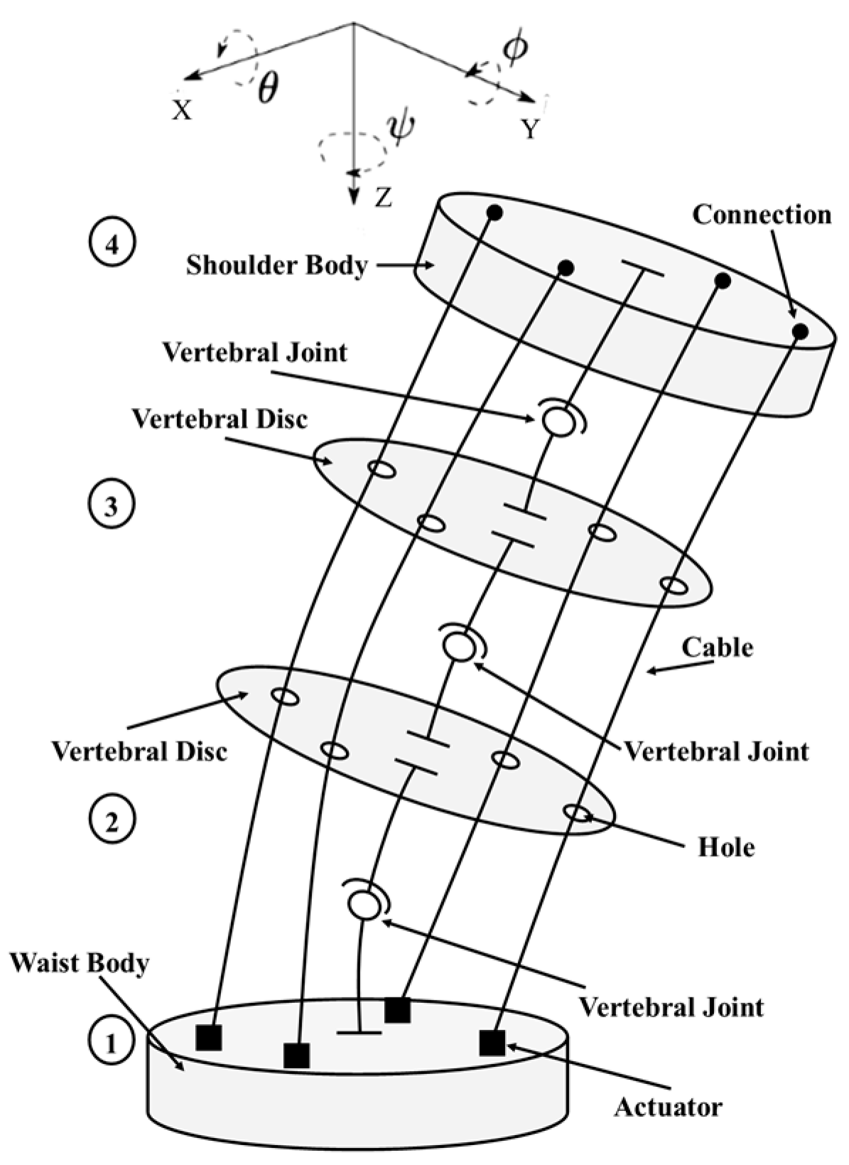
Figure 1. A kinematic design scheme of CAUTO (CAssino hUmanoid TOrso) with a human-like structure.
Inventions 02 00017 g001
Figure 2. Conceptual design for a humanoid torso: (a) human-inspired FSU scheme, (b) structure of the CAUTO torso.
Inventions 02 00017 g002
Figure 3. Mechanical design: (a) CAD model with characteristic points, (b) FEM computation results.
Inventions 02 00017 g003
Figure 4. CAUTO prototype at LARM in Cassino: (a) the torso only, (b) the humanoid assembly.
Inventions 02 00017 g004
Figure 5. A snapshot of the torso while bending with a payload of 1.150 kg on the back.
Inventions 02 00017 g005
Figure 6. Acquired data from the IMU sensor during the test in Figure 5: (a) angular displacements; (b) accelerations.
Inventions 02 00017 g006
Figure 7. Measured power consumption during the test in Figure 5.
Inventions 02 00017 g007
Figure 8. A snapshot of the torso lifting a payload of 0.560 kg using the arms.
Inventions 02 00017 g008
Figure 9. Acquired data from the IMU sensor during the test in Figure 8: (a) angular displacements; (b) accelerations.
Inventions 02 00017 g009
Figure 10. Measured power consumption during the test in Figure 8.
Inventions 02 00017 g010