1. Introduction
Robots have been advancing exponentially over the last three decades, beyond the traditional bounds of industrial applications, service, and even towards the sharing of social spaces with human beings. The report mentioned in [
1] indicates about 47% of the total US employment will be replaced by the robots or any other means of artificial intelligence (AI) in the near future. The work mentioned in [
2] points to the improvement of productivity and safety enhancement of numerous hazardous service tasks such as welding, weight lifting, cleaning, etc. Façade cleaning of high-rise buildings and skyscrapers is one among these tasks that requires humans to risk their life and limb. In recent decades, skyscrapers, including the Burj Khalifa [
3,
4,
5,
6] in Dubai and Shanghai Tower [
7,
8,
9] in Shanghai, have been known for their cutting-edge construction technologies and processes. Even in the construction and maintenance of such modern skyscrapers, outmoded methods were used for glass façade cleaning and maintenance. In the case of buildings, including the Burj Khalifa, equipment, such as a “gondola”, were not used extensively and humans were employed to clean the façades with the help of hanging guyline ropes. The above mentioned cleaning practice possess high chances of accidents and concomitant casualties, which may result in the loss of life. Numerous accidents have been reported even with the use of a gondola for façade cleaning jobs. For instance, the sudden blow of storm at Shanghai World Financial Center [
10] resulted in the loss of control of gondola. In another example, the gondola got suspended at a height of 240 m during the maintenance of the World Trade Center in New York city [
11]. The involvement of robots in scenarios like glass façade cleaning can potentially minimize the risk of accidents and maximize the productivity.
We have identified plenty of research works on the robot involved solution for the façad cleaning, which have sprouted up in a decade. A series of sky-cleaners that are driven by pneumatic actuators for the concurrent locomotion and cleaning of a glass wall by using the vacuum suction cups are discussed in [
12,
13]. The works mentioned above explore sky-cleaners with suction cups on the both ends of actuators in the
X–
Y stage and suction cups attached to a vacuum pump [
14]. Serbot AG, an industrial company in Switzerland, has developed a wall—solar panel cleaning robot named GEKKO [
15]. GEKKO is equipped with a vacuum suction cup based crawler that can rotate horizontally. The crawler has a semicircular structure with a straight line on one side and an arc line on the other, which helps to achieve both linear and rotational motions. By varying the number of brushes and the crawlers, the robot can be manually reconfigured to make itself adaptable to various wall areas. Seo et al. has developed ROPE RIDE [
16], which can climb vertical surfaces by utilizing a rope dropped down from the top of the building. The ROPE RIDE is installed with two additional propeller thrusters to ensure a strong attachment to the wall. A new wall cleaning unit using an impedance control system is proposed in the work mentioned in [
17]. As an extended work, authors also experimentally demonstrated the effectiveness of the force control system to press the brushes into the wall by exerting a constant force [
18]. Furthermore, Fraunhofer IFF, a research institute, developed a wall cleaning robot named SIRIUS [
19,
20,
21,
22]. The SIRIUS robot is capable of performing an up-and-down motion on a vertical surface, using a crane installed on buildings for façade maintenance. The robot adheres to the wall by the suction system and moves with the help of linear actuators [
23,
24,
25]. Even though the existing robot-aided solutions for façade cleaning each excel in their effectiveness and experimental results, the performance of the current robots are constrained to their target buildings. Precisely, the robots require additional equipment such as a crane, i.e., the system is still requires significant development to adapt to various building architecture. Hence, adaptability is a factor that lacks in the present façade cleaning scenario. In this research article, we present the development of a highly modular glass façade cleaning robot. The robotic cleaning system introduced in this work, that operates independently on the building structure demands a system with variable morphology. A self-reconfigurable robot is one of the potential solutions to realize alternation of morphology and maximize the adaptability. Our previous works prove that nested reconfigurable robots possess higher versatility than the typical self-reconfigurable robots [
26,
27,
28]. Hence we are exploiting a nested reconfigurable design concept for the development of a wall climbing robot system for glass façade cleaning.
Our previous works [
26,
27,
28] covers a brief concept and scheme of the nested reconfigurable design principle we used for the development of the proposed robot. The nested reconfigurable system is capable of maximizing the flexibility and the modularity corresponding to various environments or tasks with different types of intra- and inter-reconfigurable modes. Moreover, this paper covers the solutions for the development of the wall climbing robot for cleaning of high rise buildings based on the nested reconfigurable design principles. Besides, the hardware and software designs challenges involved in the implementation of the nested reconfigurable design principle are also included. We have conducted real time experiments to analyze the movement of the developed robot platform on a typical rectangular glass window, and analyzed the locomotion and the ability to adhere to the glass surface. The rest of the paper is organized as follows:
Section 2 summarizes the concept and scheme of the nested reconfigurable design principle and specific hardware/software design challenges are proposed.
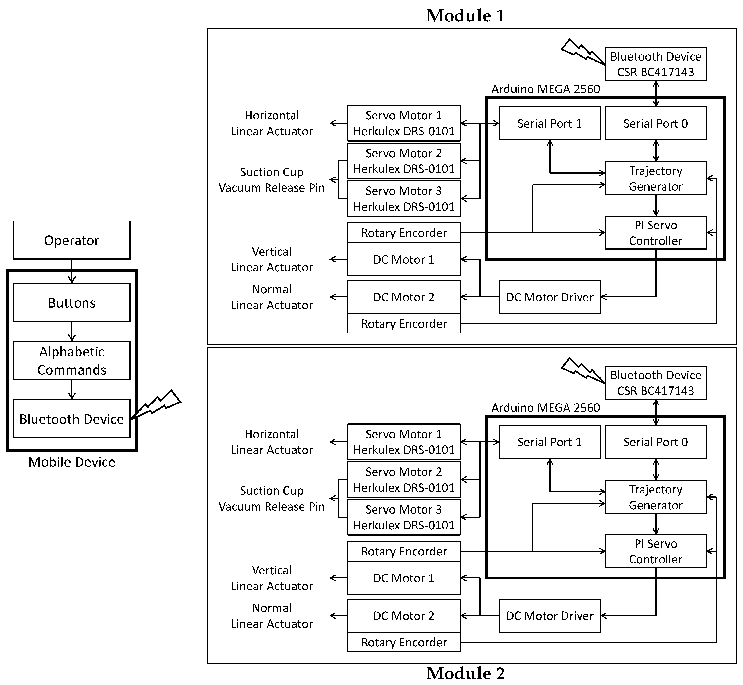
Section 3 develops the platform. A system architecture for the platform is reported in
Section 4.
Section 5 concludes this paper.
2. Nested Reconfigurable Design Challenges for a Glass Façade Cleaning Robot
Generally, the implementation of nested reconfigurable design principles on robotics opens up the scope for achieving numerous tasks that are difficult to achieve using a fixed morphology robot. In the case of glass façade cleaning, the robot design must satisfy the two factors we mentioned below.
terrain adaptability:
- -
adaptability to window shapes
- -
ability to avoid obstacles (window frames)
cleaning ability:
- -
effective cleaning mechanisms
- -
effective cleaning strategy
The execution of cleaning tasks varies according to several external factors associated with the surfaces to be cleaned. For example, the cleaning of a dry glass surface requires the execution of washing. Whereas, the cleaning of a wet glass surface doesn’t require the washing process to be done. Similarly, brushing must be executed to clean the walls of buildings near desert regions because brushing is essential to remove the sand particles trapped inside the crevices of glass windows. Hence, the robot has to be designed in such a manner that it should be able to traverse and clean any building irrespective of its architecture. “Terrain adaptability” refers to the locomotion capability of the robot on glass frames having different shapes. Typically, the glass panels can be observed in five different shapes including horizontally long, vertically long, parallelogram, trapezoidal, and curvilinear, as shown in
Figure 1. Moreover, the shape of the glass panels can be a combination of these five shapes to form a complex shape such as a horizontally-long-parallelogram, vertically-long-trapezoidal, etc. Hence, the robot must adapt to the glass panel having a complex geometry to execute a locomotion independent of the architecture of a building. Even though there exist glass panels with numerous shapes, all of them can be categorized into two. From the close observation on the geometry of various glass panels, we can infer that the window size and the window shape are the two key parameters that characterize all the glass panels. In this context, we define the window size as ratio of horizontal and vertical dimensions of the glass window to be cleaned. The horizontally-long-parallelogram and vertically-long-parallelogram are different descriptions belonging to the same category: the parallelogram. Hence the robot design should be capable of adapting to different window size and window shape to achieve the terrain adaptability factor.
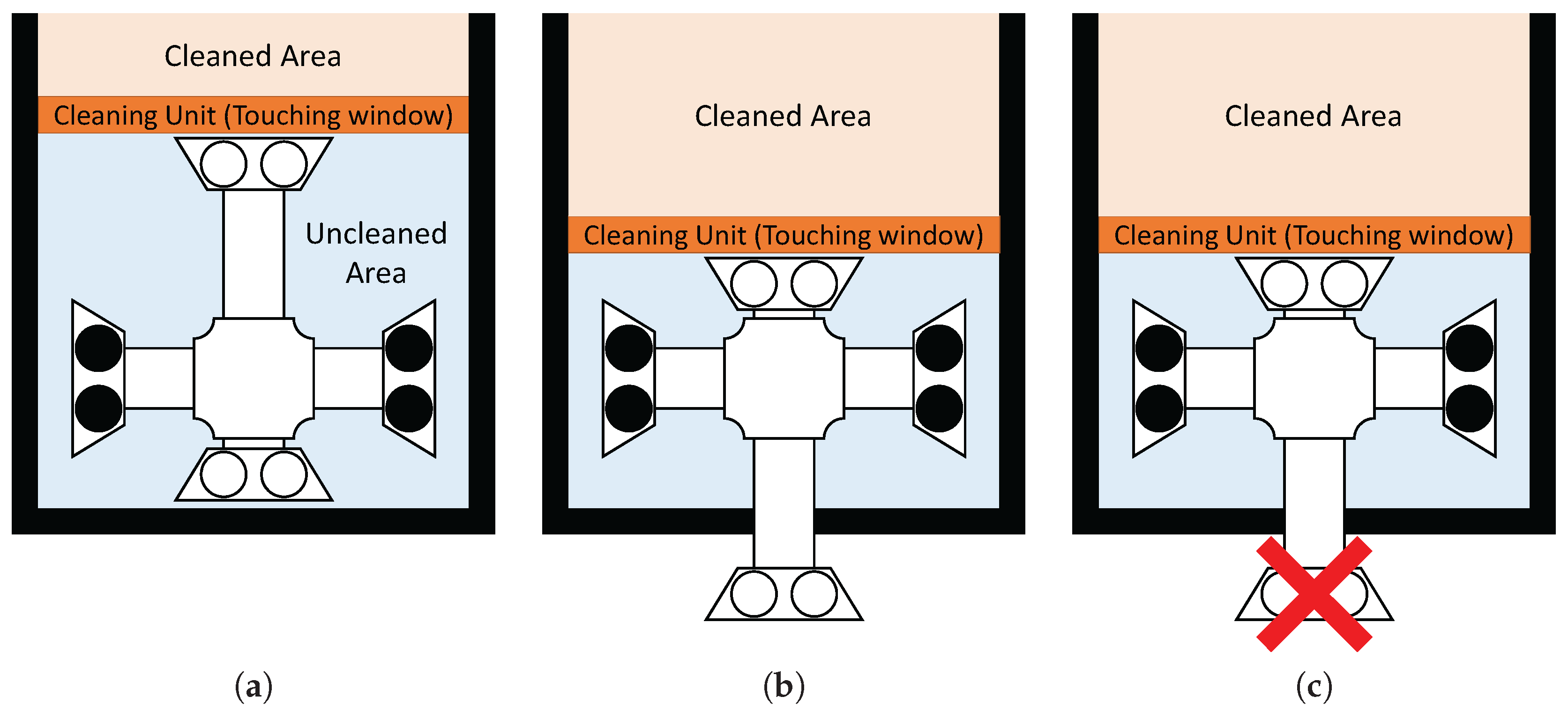
Cleaning ability, the second factor to be considered for the design of the proposed system refers to the identification of the best method to achieve effective cleaning. To identify the efficient cleaning mechanism for the robot, we observed the way of glass façade cleaning done by experts. For manual cleaning, the scrubber and squeegee are the primary tools used by experts. The experts clean glass walls by approaching the glass surface to be cleaned, washing the dirt off by using the scrubber and cleaning liquid, and finally wipe the dust residue using a squeegee (see
Figure 2). We identified that to ensure an effective cleaning, experts clean the window from top to bottom and ensure the movement of the squeegee such that it traces the surface covered by the scrubber. Besides, they ensure the complete contact of the squeegee over the glass surface during cleaning and cleaning is done towards a single direction (see
Figure 2 (
b)→(
c)→(
d)).
The strategy we adopt to realize both terrain adaptability and cleaning ability is the usage of multi-layer reconfigurability.
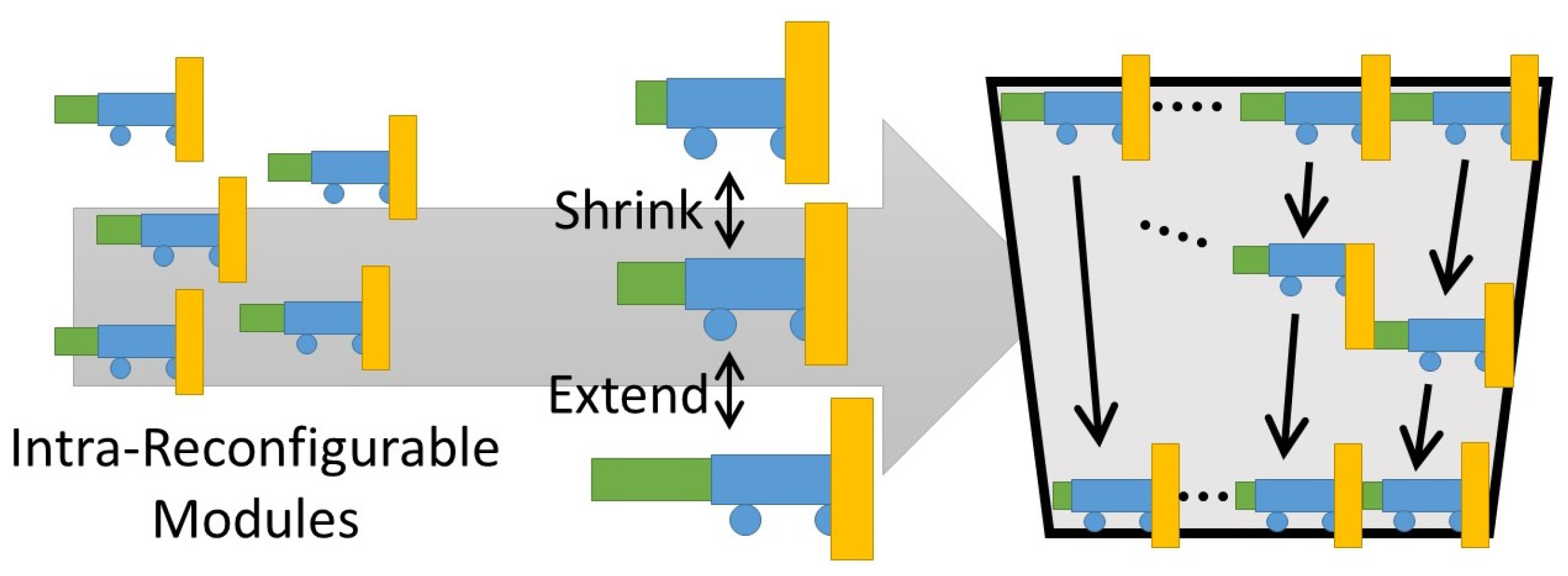
Figure 3 shows a solution for window size and window shape adaptation that belongs to the factor “terrain adaptability”. Using a fixed number of robot modules, the extension and contraction of individual modules helps the robot system to adapt to various window shapes. For instance, if the window shape is trapezoidal, the extension and contraction of individual modules helps the system to traverse from the broader end to narrower end. On the other hand, a different trapezoidal glass window with a larger size can be cleaned by increasing the number of modules of the same kind and vice versa. The solution we identified is a modular system that consists of both intra- and inter-reconfigurability in hardware. The robot design is individually extendible (intra-reconfigurable) and is capable of conjugating with other modules (inter-reconfigurable). The intra-reconfiguration of each module helps the robot to adapt to various window shapes. Similarly, the system becomes adaptable to window size by varying the number of robot modules to be deployed.
Figure 4 shows the identified cleaning mechanism and cleaning strategy for achieving cleaning ability. The cleaning ability can be accomplished by inter-reconfiguration of multiple modules. For instance, a two-robot system equipped with a squeegee next to the scrubber can execute the cleaning of the window from top to bottom. The scrubber can trace the movement of the squeegee and it can clean toward the one direction as well. The challenges of the hardware and software parts of the proposed robot system are listed below:
3. Mechanical Design
The design challenges for the glass façade cleaning robot is discussed in
Section 2. In this section, we discuss the hardware design of the robot system. We formulated the mechanical design of the proposed robot modules based on the nested reconfiguration principles and identified hardware design challenges.
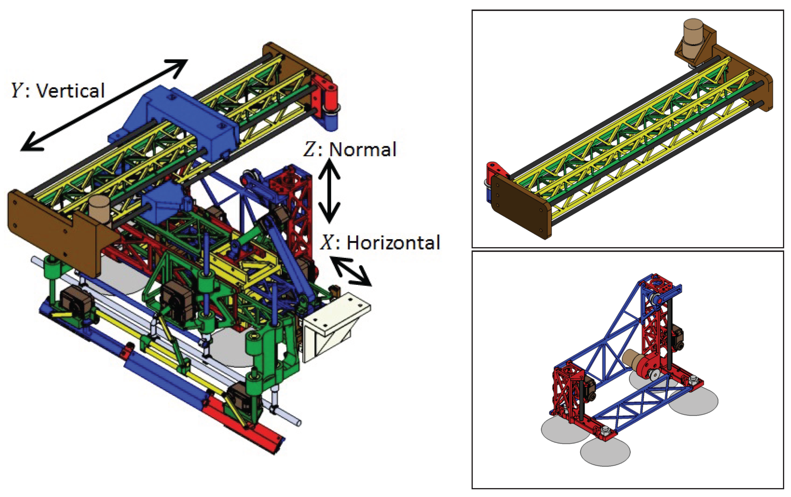
Figure 5 shows the CAD design of the developed module. The designed module consists of three linear actuators, to enable actuation on
X,
Y, and
Z directions. The strong attachment to the glass surface is achieved using suction cups. Moreover, the cleaning unit is mounted on the linear actuator such that the unit can move in horizontal directions. This arrangement helps the robot to re-configure its length by itself (inter-reconfiguration) by performing the extension.
The three actuators perform three different tasks. The actuator on the horizontal directions helps to achieve the extension action, whereas the actuator in the normal direction helps to avoid the obstacles (the window frames that projects out from the glass surface) and traverse through the wall. The actuator in the vertical direction does the attachment of a nearby module. There are two common methods for achieving wall climbing. One is the legged type method as in the sky cleaners mentioned in [
12,
13], the robot proposed by Yano et al. [
29,
30], and by Kawasaki et al. [
31]. Another method for wall climbing is the wheel/crawler-type, as in the works presented by Gao et al. [
32,
33], Miyake et al. [
34,
35], and Kim et al. [
36,
37]. The robots that belong to the legged-type family have discontinuous contact points on the glass surface and are controllable within the range of operation of the robot. However, a leg of the robot (a part of the negative pressure generating area) has to leave the surface of contact to achieve movement. Hence, the suction mechanism of the robot has to generate a large scale negative pressure during every locomotion. On the other hand, wheeled or crawler-type robots have continuous contact points on the glass surface. Unlike the legged type robots, wheeled type robots could generate adhesion force uniformly on the surface of contact during movement. In a glass cleaning scenario, it is necessary to overcome obstacles such as the window frames and protrusions on the glass surfaces to perform an efficient transition from one glass panel to the other. Comparing with wheeled robots, a pragmatically better robot design to achieve obstacle avoidance is the legged variant. Furthermore, wheeled/crawler-type robot design can be further subdivided into an
X–
Y stage design and a biped-type. As we discussed in the design challenges mentioned in the second section, the module has to move the cleaning unit from the top of the window to the bottom continuously to achieve effective cleaning. In the case of an
X–
Y stage legged robot, it is hard to realize complete area coverage due to its design limitations.
Figure 6 explains the of locomotion of the
X–
Y stage legged type robots in the particular context in which the robot fails to accomplish complete area coverage. On the other hand, the same motion can be achieved in a biped design with the help of an enhanced control strategy (
Figure 7). Hence, we choose the characteristics of the biped-type robot for the proposed design. We developed the robot module such that all modules are equipped with a biped mechanism and the
ith module always conjugates with the
module. Another characteristic of the proposed design is the individual controllability of the scrubber and squeegee in the cleaning unit because both scrubber and squeegee are required to move from the top of the window frame to the bottom.
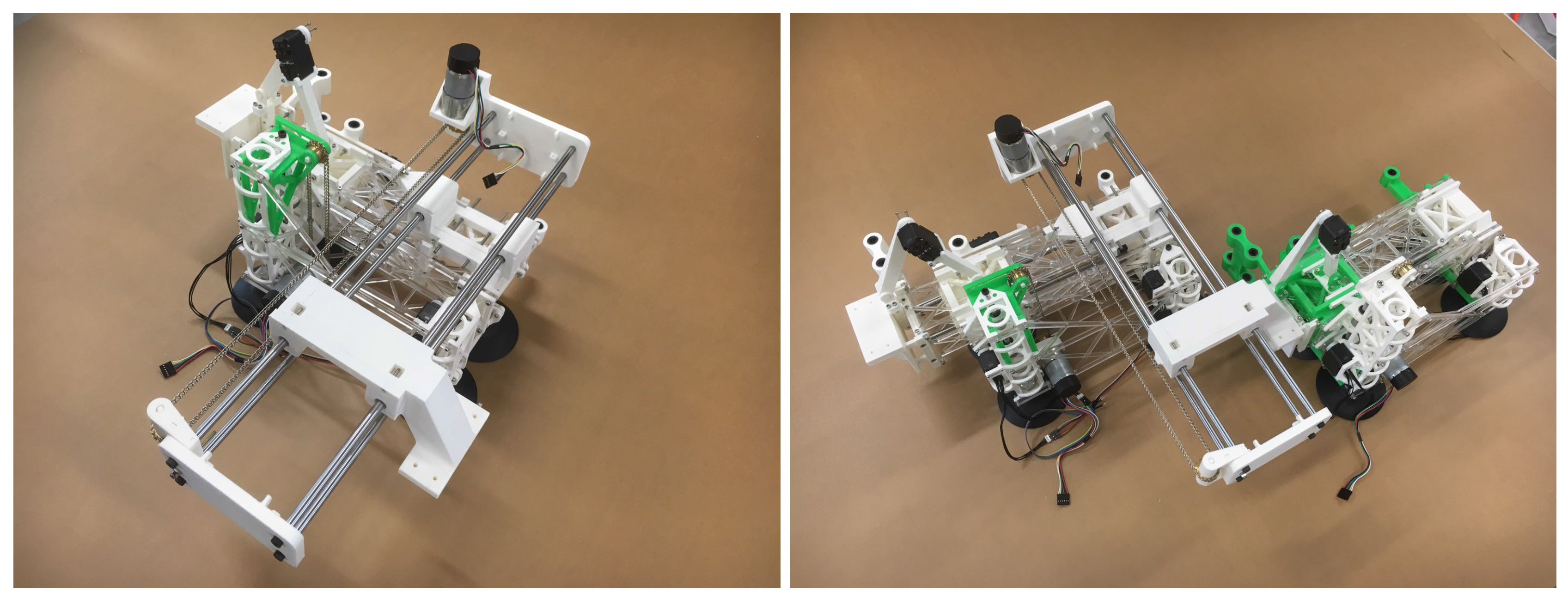
The CAD diagram of fabricated robot modules is shown in
Figure 8. For the linear actuators in both normal and vertical direction, we adopted the ladder chain and sprocket mechanism. We used a DC motor (131:1 Metal Gearmotor 37 D × 73 L mm with 64 CPR Encoder, 18 kgf·cm of maximum torque, 80 rpm free-run, product by Pololu) equipped for generating the driving force for the actuators. Since the maximum torque from the DC motor is 18 kgf·cm, the maximum attainable force is 14.63 kgf. Since the maximum rotational speed of the DC motor is 80 rpm, the maximum feed speed is 0.10 m/s. The structural weight of the module to be fabricated is 5.423 kg including battery and all peripherals. For the calculations we took the weight of the module as 6 kg, considering the safety of the prototype and envisioning the fabrication of a real robot that is a prototype. The factor of safety we maintained is 2.98. Regarding the linear actuator in the normal direction, we calculated the displacement
[cm] by performing the calculations as mentioned below:
Let the angle of rotation of the motor be
[rad] and the displacement is
[cm],
where
[cm] represents the radius of the sprocket associated with the ladder chain system. We chose
cm for this module. Similarly, for the linear actuator in the vertical direction, a sprocket and chain ladder mechanism that can create a movement towards both sides of the ladder chain is used. Let the angle of rotation of the motor be
[rad], then the relative distance between each stage
[cm] is calculated as follows:
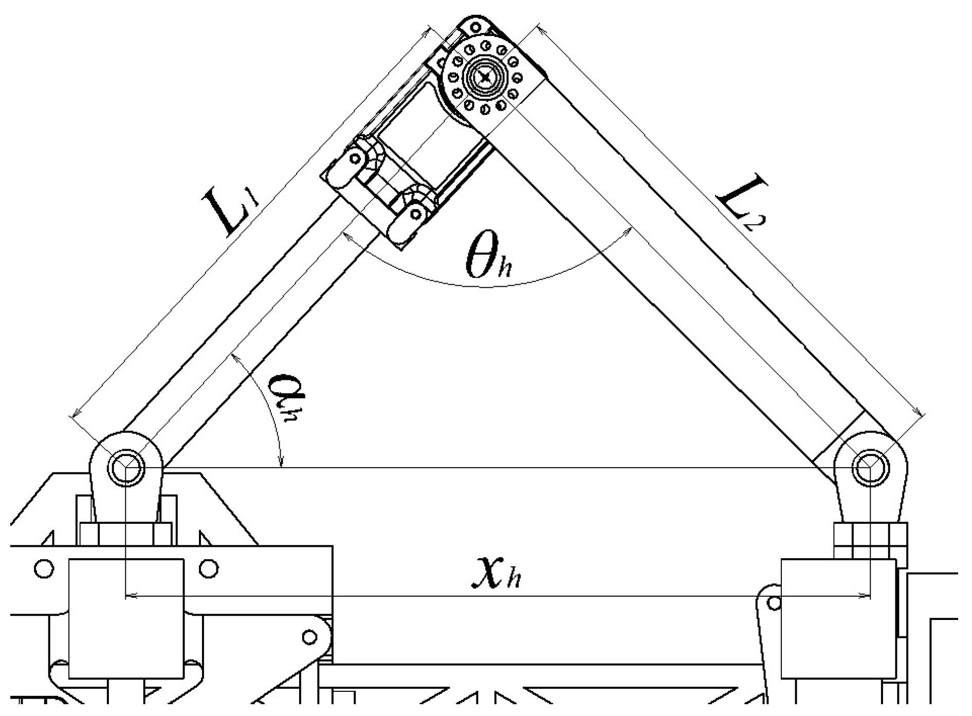
For the linear actuator in the horizontal direction, we used the slider-crank mechanism. The servo motor (HerkuleX DRS-0101, 12 kgf·cm of stall torque, 0.166 s/60 deg of maximum speed) is used as the driving force generator for the linear actuators. Let the angle of rotation of the motor and the length of each link be
[rad],
, and
(as shown in
Figure 9). From the law of cosines, the length of extension is calculated as:
In addition, let an angle between
[cm] and
[cm] be
[rad], and the length from
[cm] to the motor axis be
[cm]. The maximum force required for the extension action
[kgf] is formulated as follows:
Note that the force in the horizontal direction is not used to support the weight of the module unless it takes an inclined configuration.
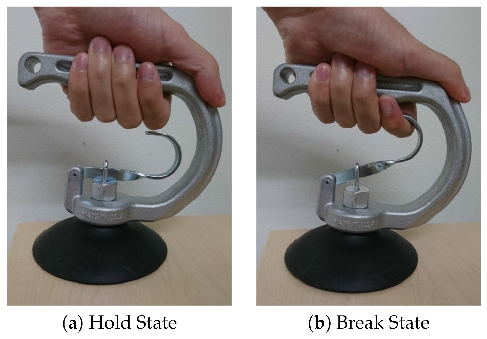
The module equips four suction cups of 10 cm diameter each, as the suction cups are used by experts for safety purpose and possess fewer chances for air leakage but are easy to release vacuum, using the pin mechanism associated with it (
Figure 10).
We automated the pulling action on the pin to release the vacuum inside the suction cup. We engaged the pin with the servo motor using a light metal chain. The tensile force generated in the chain during the rotation of servo motors does the automatic pulling of the pin associated with the suction cups. We used Herkulex DRS-0101 servo motors (manufacture: DST Robot ,Jiksan-eup, Korea) to achieve the task mentioned above. In general, the adsorption force of a suction cup
W [N] is
where,
C [cm
],
P [−kPa], and
f represent the area, vacuum pressure, and safety factor of the suction cup, respectively. Since four suction cups with 10 cm diameter each are equipped in the module,
×
×
cm
and the safety factor is set as 1/8 based on the standard value used for vertical lifting cases.
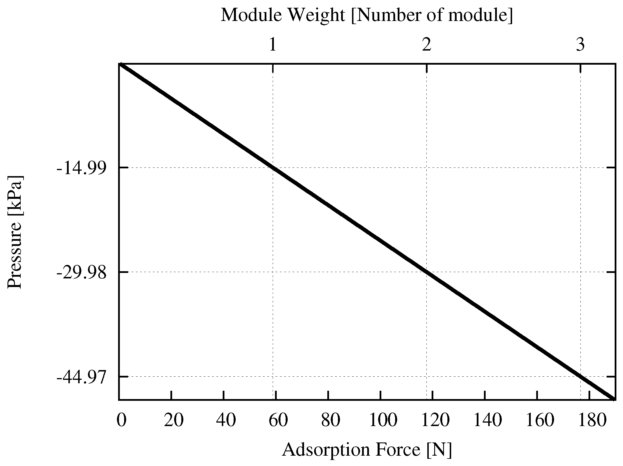
Figure 11 shows the linear variation between the required vacuum pressure to the adsorption force.
From
Figure 11 and (
1), the required vacuum pressures to hold the modules one, two, and three are −14.99, −28.98, and −44.97 kPa, respectively. Since a passive suction cup (without any vacuum generator) is utilised in this module, the vacuum pressure occurs due to the variation of volume inside the suction cup, assumed as a circular cone in our calculations. The pressure inside the chamber after pushing the suction cup equals the external air pressure, assumed to be atmospheric pressure. When the suction cup is restored to its original state, when we release the pushing force, the vacuum pressure is generated. If the vacuum pressure thus generated is greater than the requirement, the suction cup can adhere to the glass surface. Let
[cm
] be the volume of the suction cup after releasing the pushing force. We deduce the condition for the module to attach on the glass surface using following calculations:
Using Boyles’ Law:
where,
[kPa] and
[kPa] are the atmospheric pressure and the required vacuum pressure, respectively, and
[cm
] is the volume of the chamber inside the suction cup before pushing it (i.e., the default state of suction cups). Hence, the required variation in volume
[cm
] required to attach the module to the glass surface is
The diameter of the equipped suction cup is
cm and the height of the chamber in its default state
cm. The chamber height after the pushing action is
[cm], thus
Hence, the pushing depth
[cm] required to adhere the module to the glass surface is
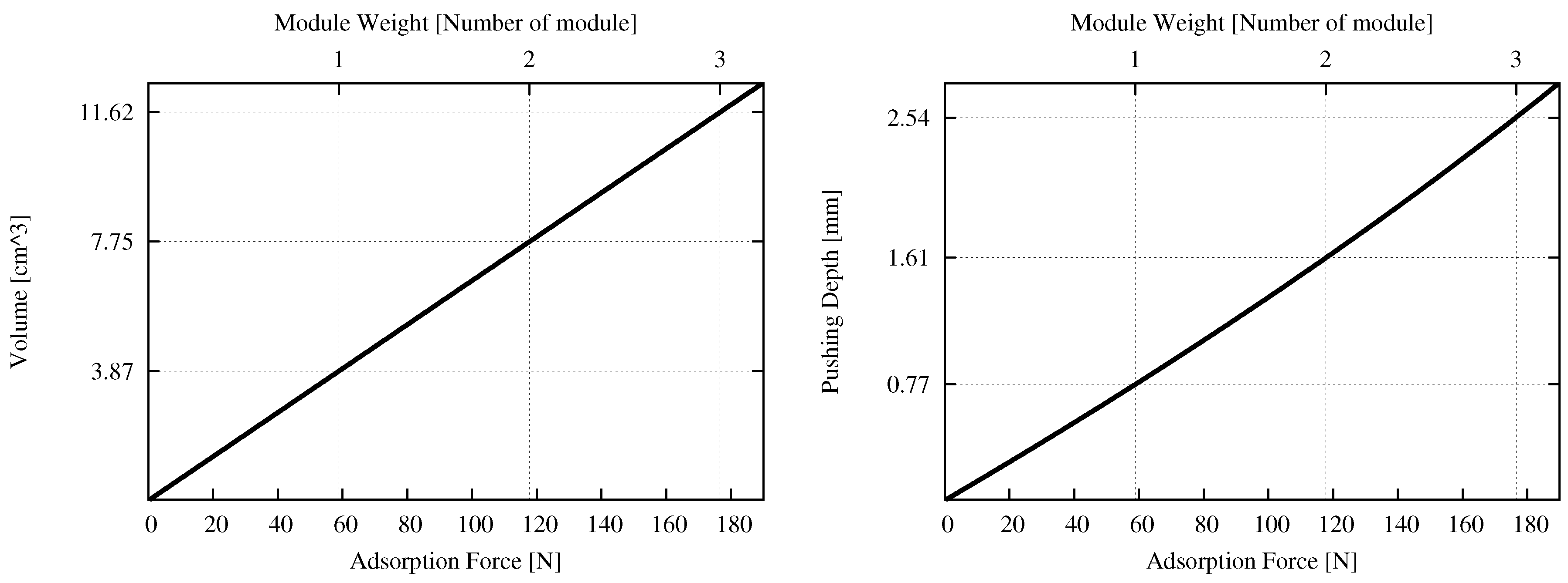
Figure 12 shows the required volume variation and the required variation in pushing depth corresponding to the adsorption force. From
Figure 12 (Left) and (
2), the required volume variation to hold one, two, or three modules is 3.87, 7.75, and 11.62 cm
, respectively. From
Figure 12 (Right) and (
3), the required pushing depth to hold one, two, or three modules is 0.77, 1.61, and 2.54 mm, respectively.


