
Article

Integrated Triboelectric Energy Harvesting and Displacement Monitoring for Low-Frequency Railway Bridge Vibrations

1
School of Mechanical Engineering, Shenyang Jianzhu University, Shenyang 110168, China
2
Beijing Institute of Nanoenergy and Nanosystems, Chinese Academy of Sciences, Beijing 101400, China
*
Authors to whom correspondence should be addressed.
Inventions 2026, 11(4), 74; https://doi.org/10.3390/inventions11040074
Submission received: 16 June 2026 / Revised: 18 July 2026 / Accepted: 21 July 2026 / Published: 23 July 2026

Abstract

Achieving sustainable structural health monitoring remains a critical challenge for intelligent railway infrastructures, where distributed sensing networks require continuous power supply and long-term maintenance. Although low-frequency railway bridge vibrations simultaneously contain harvestable mechanical energy and structural state information, existing systems generally exploit these functionalities independently, resulting in increased system complexity and limited energy utilization efficiency. Here, we present an integrated triboelectric vibration energy harvesting and displacement monitoring device (THM) for low-frequency railway bridge vibrations. By incorporating a quasi-zero-stiffness (QZS) mechanism, the energy harvesting unit achieves an enhanced low-frequency response, delivering an open-circuit voltage of 280 V, a short-circuit current of 28 μA, and a peak power of 9 mW. The device charges a 22 μF capacitor to 4 V within 45 s under 1.5 Hz excitation, demonstrating its capability to power low-power electronics. Simultaneously, a freestanding triboelectric sensing unit enables real-time girder–pier displacement monitoring, displacement-direction identification, and structural safety warning, exhibiting excellent linearity (R2 = 0.9886) and stable operation over 20,000 cycles. This work provides an integrated strategy for simultaneously harvesting energy and monitoring structural displacement from low-frequency railway bridge vibrations, offering a promising route toward self-sustained intelligent bridge health monitoring systems.

1. Introduction

Railway bridges are indispensable components of modern transportation networks, ensuring efficient connections across rivers, seas, and mountainous regions while supporting the rapid expansion of high-speed railway systems worldwide [1,2,3]. As bridge spans continue to increase and structural configurations become increasingly sophisticated, guaranteeing long-term operational safety and reliability has become a critical challenge in railway infrastructure management [4,5]. During service, railway bridges are continuously subjected to dynamic excitations induced by train passages, generating low-frequency and small-amplitude vibrations throughout the entire structure [6,7,8]. These vibrations not only reflect the operational state of the bridge but also contain valuable information regarding structural integrity and potential damage evolution. In particular, the relative displacement between girders and piers is widely recognized as a key indicator for evaluating load transfer behavior, structural stability, and service performance. Continuous monitoring of girder–pier displacement is therefore essential for the early identification of structural abnormalities and the prevention of catastrophic failures [9]. To realize real-time structural health monitoring, increasing numbers of distributed sensing nodes are being deployed throughout railway bridge systems [10,11,12]. However, the long-term operation of these monitoring networks remains heavily dependent on batteries or external power supplies, leading to substantial maintenance costs, limited deployment flexibility, and reduced system sustainability. These challenges become even more pronounced in remote or inaccessible bridge environments, where routine maintenance and battery replacement are difficult to implement. Consequently, developing technologies capable of simultaneously providing sustainable power supply and autonomous structural monitoring has become a crucial requirement for next-generation intelligent bridge infrastructures.
Ambient bridge vibrations represent a ubiquitous and sustainable energy source that can potentially power distributed monitoring systems. To exploit this resource, various vibration energy harvesting technologies based on electromagnetic and piezoelectric conversion mechanisms have been extensively investigated [13,14,15,16]. Although these technologies exhibit attractive power generation capabilities, their performance is often compromised under the low-frequency and small-amplitude vibration conditions characteristic of railway bridges [17,18,19]. More importantly, conventional energy harvesters are primarily designed for energy conversion and generally lack the capability to directly provide structural sensing information [20]. As a result, separate sensing modules are usually required, increasing system complexity, installation costs, and maintenance requirements. Therefore, an important challenge remains: how to efficiently utilize low-frequency bridge vibrations not only as a sustainable energy source but also as an information carrier for structural monitoring. The emergence of triboelectric nanogenerators (TENGs) provides a promising pathway toward addressing this challenge [21,22,23,24]. By coupling contact electrification and electrostatic induction, TENGs can simultaneously convert mechanical motions into electrical energy and generate electrical signals that inherently reflect external mechanical stimuli [25,26,27,28,29,30]. Benefiting from their lightweight structures, flexible configurations, high sensitivity, and excellent adaptability to low-frequency mechanical excitations, TENGs have attracted significant attention in energy harvesting, self-powered sensing, wearable electronics, and intelligent infrastructure applications [31,32,33,34].
Recent studies have demonstrated the feasibility of triboelectric technologies for bridge-related applications, including bridge vibration energy harvesting, girder settlement monitoring [35,36,37], deformation sensing [38,39], and structural response detection [40,41]. For example, Tan et al. developed a bistable triboelectric nanogenerator capable of broadening the low-frequency response bandwidth for bridge vibration energy harvesting [42]. Zhang et al. reported a triboelectric real-time sensing system for self-powered monitoring of bridge dynamic responses through the integration of TENG sensing units and wireless data acquisition modules [43]. These studies collectively verify the considerable potential of triboelectric technologies in bridge structural health monitoring. Despite these advances, existing triboelectric systems predominantly focus on either energy harvesting or structural sensing as independent functionalities. From the perspective of energy harvesting, efficiently extracting electrical energy from railway bridge vibrations remains challenging because of their ultra-low-frequency and small-amplitude characteristics. From the perspective of structural monitoring, most self-powered sensing systems are designed for unidirectional motion detection or large-stroke displacement measurements, exhibiting limited capability in resolving bidirectional micro-displacements under realistic bridge operating conditions. More fundamentally, current triboelectric systems rarely exploit the dual attributes of bridge vibrations as both energy sources and structural information carriers. The integration of efficient low-frequency vibration energy harvesting and high-resolution displacement monitoring within a single triboelectric platform therefore remains largely unexplored. Addressing this challenge is essential for developing sustainable, compact, and intelligent structural health monitoring systems for future railway infrastructures.
Herein, we present an integrated triboelectric vibration energy harvesting and displacement monitoring device (THM) for low-frequency railway bridge vibrations. Distinct from existing independent energy harvesting or sensing systems, the THM is characterized by three key advancements. First, by incorporating a quasi-zero-stiffness (QZS) mechanism with linear elastic elements, the system achieves stiffness matching and enhanced low-frequency response, enabling efficient harvesting of bridge vibration energy. The energy harvesting unit delivers an open-circuit voltage of 280 V, a short-circuit current of 28 μA, a transferred charge of 225 nC, and a peak output power of 9 mW, demonstrating its capability to power low-power electronic devices and wireless sensing nodes. Second, we integrate a freestanding triboelectric sensing unit to achieve real-time girder–pier displacement monitoring and direction identification, overcoming the limitations of previous self-powered systems in concurrent multi-dimensional motion sensing. Finally, the THM maintains high linearity and stable performance over long-term operation. Combined with a LabVIEW-based visualization and warning interface, the proposed system enables simultaneous energy harvesting and structural monitoring within a unified triboelectric platform. This work provides a practical strategy for transforming low-frequency railway bridge vibrations into both electrical energy and structural information, offering a promising route toward sustainable and intelligent railway bridge health monitoring systems.

2. Materials and Methods

2.1. Deployment and Structural Design of the THM

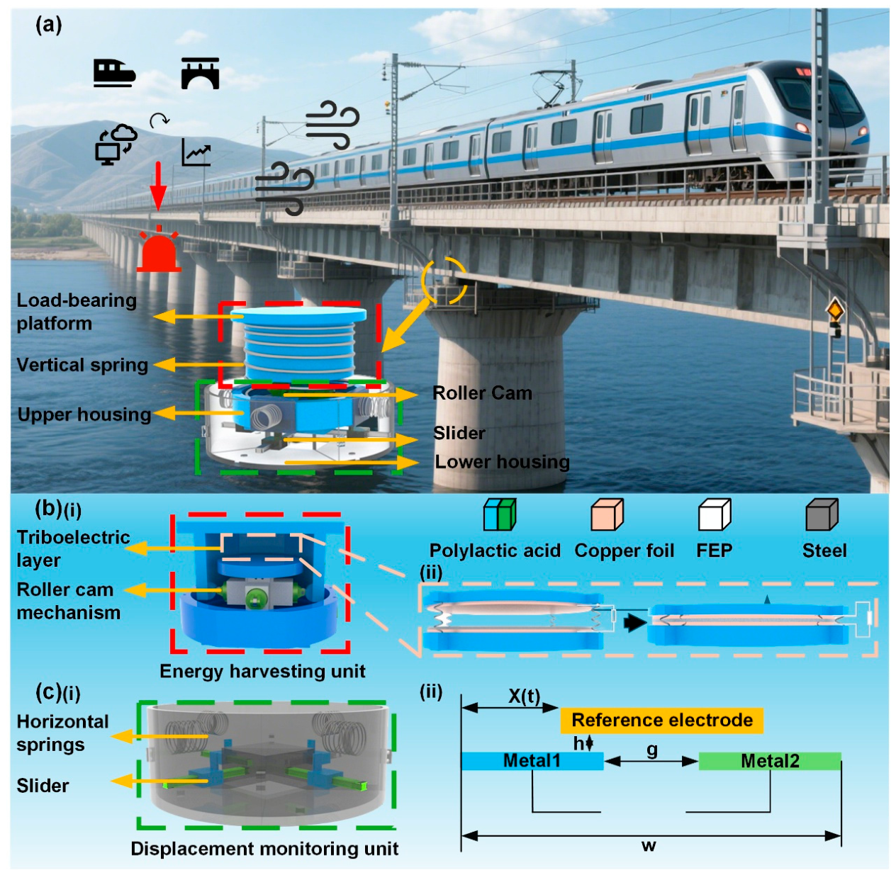
The overall architecture and operational principle of the railway bridge vibration energy harvesting and displacement monitoring device (THM) are illustrated in Figure 1. To simultaneously utilize low-frequency bridge vibrations as both energy sources and structural information carriers, the THM integrates an energy harvesting unit and a displacement monitoring unit within a unified optical platform (YH-JM-K-06-06, GANGZHOU YIHANG TECHNOLOGIES CO LTD, CHN, Ganzhou, China). The device is installed at the girder–pier connection of railway bridges. The dimensions of the THM (220 mm × 220 mm × 120 mm) are optimized to fit the pier-top platforms of standard railway bridges, ensuring a compact design that avoids structural interference within the bearing zone. It continuously harvests ambient vibration energy induced by train passage and wind excitation while monitoring the relative displacement between the girder and the pier in real time (Figure 1a). The THM mainly consists of a quasi-zero-stiffness (QZS) mechanism, an energy harvesting unit, a displacement monitoring unit, and upper and lower housing structures. The energy harvesting unit is designed to efficiently capture low-frequency bridge vibrations, as shown in Figure 1b(i). A nonlinear QZS mechanism is established by coupling a negative stiffness subsystem, composed of roller cams, horizontal springs, and sliders, with a vertical spring. This stiffness-matching design significantly reduces the effective natural frequency of the system, enabling resonance enhancement under low-frequency bridge excitation. In addition, the roller-cam mechanism amplifies the vibration displacement of the load-bearing platform while constraining the motion to a single vertical degree of freedom. Consequently, the amplified motion periodically drives the triboelectric layers into contact and separation, converting ambient vibration energy into electrical energy through triboelectrification and electrostatic induction (Figure 1b(ii)).
To simultaneously acquire structural state information, a freestanding triboelectric-layer displacement monitoring unit is incorporated into the THM, as illustrated in Figure 1c(i). The monitoring unit consists of a precision slider, a guide rail, centering springs, and triboelectric electrode arrays. The upper housing is mechanically connected to the bridge girder, whereas the lower housing is fixed to the pier. Relative displacement between the girder and pier drives the slider to reciprocate along the guide rail through a matched driving protrusion–groove structure. A fluorinated ethylene propylene (FEP) film attached to the slider serves as the negative layer, while periodically arranged copper electrodes function as the positive stator. As the FEP layer slides across the electrode array, periodic charge redistribution is induced, generating electrical signals that directly correspond to the displacement magnitude and motion direction of the bridge structure (Figure 1c(ii)). Therefore, the THM establishes an integrated triboelectric platform capable of simultaneously harvesting vibration energy and monitoring structural displacement. By coupling vibration-to-electricity conversion with displacement sensing, low-frequency railway bridge vibrations are utilized not only as sustainable energy sources but also as carriers of structural state information, providing a foundation for self-sustained structural health monitoring.

2.2. Mechanical Analysis of the Energy Harvesting Unit

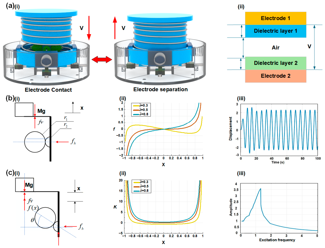
Figure 2 illustrates the structural design and non-linear dynamic characteristics of the THM energy harvesting unit. The dimensionless force–displacement characteristic curves reveal the low-stiffness properties of the quasi-zero-stiffness (QZS) mechanism near the equilibrium position. By utilizing the negative stiffness element to compensate for the system’s linear positive stiffness, this design effectively reduces the initial response frequency and shifts the vibration response toward the lower range. Based on this, Figure 2a(i) illustrates the working principle of the energy harvesting unit: when an external vertical force f v is applied, the horizontal springs experience a corresponding spring force f h due to compression, and the energy harvesting unit operates in the vertical contact-separation mode to collect vibration energy in this direction. Based on the mechanical analysis of the cam-roller-spring mechanism, the relationship between the applied force f v and the vertical displacement x can be derived as follows:
f ( x ) = M g f v 2 f h tan θ
The vertical spring is compressed by a deflection Δ x to support the payload at the static equilibrium position. Therefore, the relationship between the force f and the displacement x is:
f ( x ) = k v x 2 k h x 1 + δ r 1 + r 2 r 1 + r 2 2 x 2
In order to further study the dynamic response of the THM energy harvesting unit, the dimensionless non-linear vibration equation is used for numerical simulation. The system parameters are non-dimensionalized to reveal the key characteristics of the THM energy harvesting unit and simplify the analysis process. The non-linear vibration equation is as follows:
d 2 x d t 2 + 2 β d x d t + k 0 x + a x n = F 0 sin ( ω t )
Here, x is the dimensionless displacement of the system, k0 is the dimensionless linear stiffness coefficient, α is the non-linear stiffness coefficient, β is the damping ratio, ω is the dimensionless excitation frequency, and F0 is the dimensionless amplitude of the external excitation force. The mass and damping parameters of the system are standardized in the dimensionless form. Detailed derivations are provided in Equations (S1) to (S10) of the Supplementary Materials.
Based on the mechanical equilibrium equations, Figure 2b(i) presents the force analysis model of the roller cams, horizontal springs, and vertical spring at the equilibrium position, showing the interaction forces between components. Consequently, Figure 2b(ii) characterizes the dimensionless force–displacement curves of the energy harvesting unit under different horizontal spring pre-compressions δ ¯ . As the pre-compression increases, the slope of the curve near the equilibrium position gradually approaches zero, which demonstrates typical quasi-zero stiffness characteristics. This indicates that the system stiffness can be effectively modulated by adjusting the pre-compression of the horizontal springs. Figure 2b(iii) illustrates the time-history displacement response of the THM energy harvesting unit under external excitation. The analysis reveals that the system exhibits non-linear oscillation behavior under low-frequency excitation. The displacement response shows transient fluctuations at the initial stage, followed by a stable steady-state vibration mode after a non-linear transition process. The periodic characteristics of the displacement signal demonstrate the low-frequency resonance mechanism of the system, where the amplitude increases when the external excitation frequency approaches the natural frequency of the system.
Figure 2c(i) illustrates the force model of the load-bearing (Mg) relative to the static equilibrium position under the external excitation force ( f v ). By optimizing the geometric dimensions of the load-bearing platform and the upper and lower housing structures, it is ensured that the roller remains in continuous contact with the roller cams throughout the movement. Figure 2c(ii) depicts the dimensionless horizontal springs characteristics under different horizontal spring pre-compressions ( δ ¯ ). The total stiffness of the system is a combination of the negative stiffness provided by the horizontal spring and the positive stiffness of the vertical spring. When the pre-compression is high ( δ ¯ = 0.8), the negative stiffness component dominates, causing the system to exhibit negative stiffness characteristics near the static equilibrium position. Conversely, for a smaller pre-compression ( δ ¯ = 0.3), the system exhibits positive stiffness. When the pre-compression parameter is set to a value of 0.5, the system achieves the quasi-zero-stiffness (QZS) state near the equilibrium position (Figure S1, Supplementary Materials). The wire diameter of the horizontal spring fundamentally governs the output performance by modulating the total system stiffness. Specifically, the wire diameter determines the horizontal stiffness k0, which in turn regulates the magnitude of the negative stiffness provided by the roller-cam mechanism. Experiments demonstrate that when the wire diameter is 0.8 mm, the negative stiffness perfectly offsets the positive stiffness of the vertical spring, driving the system into the QZS state. As shown in Figure 2c(iii), this state significantly reduces the natural frequency of the THM, facilitating the harvesting of low-frequency excitation (1–3 Hz) from railway bridge vibrations. To further clarify the physical mechanism underlying the continuous generation of electrical signals by the THM, COMSOL Multiphysics 6.4 is employed to simulate the potential distribution during the separation of the triboelectric layers (Figure S2, Supplementary Materials). The simulation results demonstrate that the potential difference between the two electrodes increases systematically as the gap between the triboelectric layers widens. This dynamic evolution of the potential distribution aligns well with the principle of electrostatic induction, which strongly validates the feasibility of achieving continuous electromechanical energy conversion through reciprocating contact-separation motion.

3. Results and Discussion

3.1. Output Characteristics of the Energy Harvesting Unit

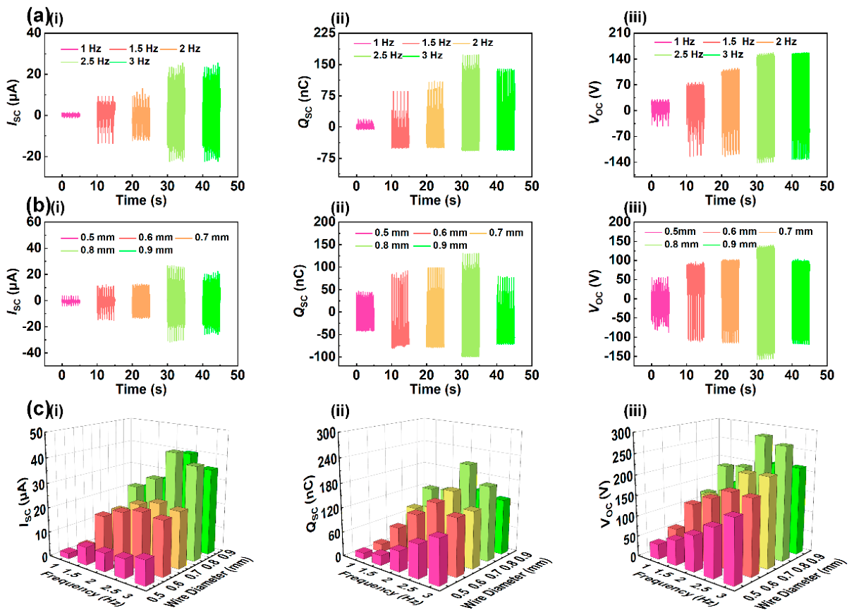
To further investigate the influence of spring stiffness and excitation frequency on the performance of the THM, a comprehensive experimental platform is developed, which incorporates capabilities for low-frequency vibration simulation and signal acquisition. The output performance of the THM energy harvesting unit under various excitation frequencies and spring stiffnesses is evaluated, and the experimental results are presented in Figure 3. By adjusting the wire diameter of the horizontal springs (0.5–0.9 mm), the influence of stiffness matching on the energy harvesting efficiency of the THM under excitation frequencies of (1–3 Hz) is investigated (amplitude: 15 mm). The excitation frequencies and amplitudes used in our experiments are based on the operational characteristics of railway bridges. Initially, with the horizontal springs diameter fixed at 0.8 mm, the output performance at different frequencies is shown in Figure 3a. As the excitation frequency increases from 1.0 Hz to 2.5 Hz, the open-circuit voltage (Voc), transferred charge (Qsc), and short-circuit current (Isc) of the system exhibit a significant increasing trend. However, when the excitation frequency further increases to 3 Hz, the performance, which is primarily limited by the mechanical response frequency and the effective contact stroke, declines. Under this condition, the triboelectric layers fail to achieve sufficient contact and separation, leading to a reduction in the effective induced charge.
Subsequently, to further determine the optimal system stiffness, the influence of the horizontal spring wire diameter on the output characteristics is discussed at a frequency of 2.5 Hz. As shown in Figure 3b, the output performance reaches its peak when the wire diameter is 0.8 mm, with the maximum Isc, Qsc, and Voc reaching 28 μA, 225 nC, and 280 V, respectively. The experimental data indicate that when the wire diameter is small (0.6 mm), the system stiffness is insufficient, leading to weak contact pressure. Conversely, an excessive diameter (0.9 mm) limits the mechanical response speed. Any stiffness configuration deviating from the optimal value limits either the effective contact area or the response speed. Therefore, a wire diameter of 0.8 mm achieves the optimal balance between charge transfer and damping characteristics, serving as the key parameter for ensuring the superior performance of the quasi-zero stiffness mechanism. To further clarify the interaction between physical parameters, Figure 3c illustrates the coupling effect of excitation frequency and horizontal spring stiffness on the performance of the THM. The experimental results indicate that the output of the energy harvesting unit increases with frequency within the range of 1–2.5 Hz. Regarding stiffness, the output performance follows a trend of increasing followed by decreasing as the horizontal spring wire diameter increases. Specifically, as the horizontal spring diameter increases from 0.6 mm to 0.8 mm, the negative stiffness effect offsets the positive stiffness of the system, which enhances the resonance response and improves the energy harvesting performance. However, as the wire diameter further increases to 0.9 mm, the excessive horizontal restoring force increases the system motion impedance, limiting the effective contact between the triboelectric layers under the fixed excitation amplitude. Therefore, the 0.8 mm wire diameter provides the optimal balance between maintaining quasi-zero-stiffness characteristics and dynamic responses, which ensures the peak performance of the mechanism.
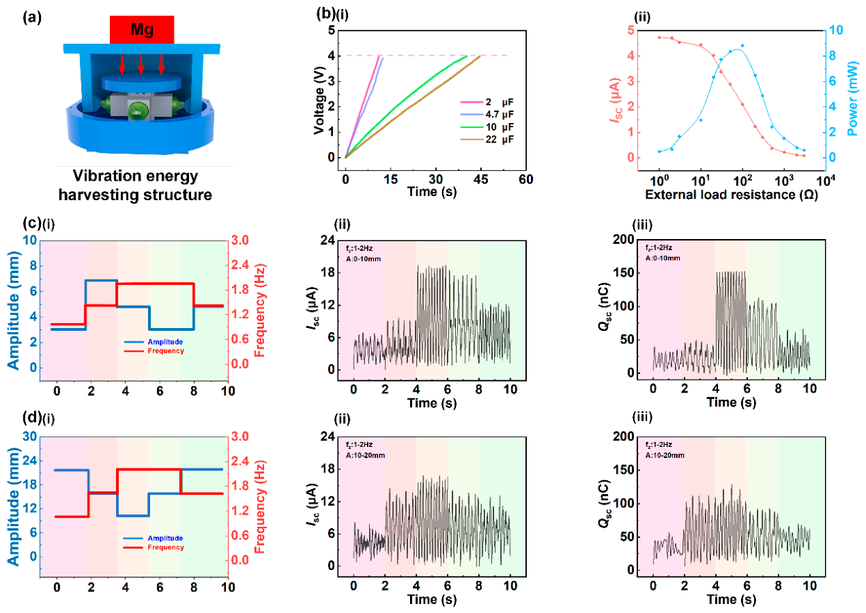
Figure 4 systematically characterizes the energy conversion performance, load matching behavior, and operational stability of the THM under complex working conditions. Figure 4a displays the stress distribution of the THM in a railway bridge scenario. Regarding energy storage and practical verification, as shown in Figure 4b(i), the system charges a storage capacitor via a rectifier circuit. Under an excitation of 1.5 Hz and 15 mm, the THM charges a 22 μF capacitor to 4 V within 45 s, which demonstrates the capability to power wireless sensor nodes. The power supply demonstration is provided in Supplementary Materials Video S1. Regarding load matching, as shown in Figure 4b(ii), the variation in the output performance with load resistance is investigated under an excitation frequency of 1.5 Hz and an amplitude of 10 mm. As the external load resistance increases, the output current decreases, while the output power exhibits a distinct peak. The maximum output power of the system is measured at approximately 9 mW, which demonstrates a favorable performance compared to similar devices, indicating the energy harvesting capability of the THM. The vibration state of railway bridges is dynamic. Therefore, to evaluate environmental adaptability, the output performance of the THM under two modes of continuous variable-frequency and variable-amplitude excitation is tested, with results presented in Figure 4c,d. Working condition 1 (frequency: 0.5–1.5 Hz, amplitude: 5–10 mm) and working condition 2 (frequency: 0.5–1.5 Hz, amplitude: 10–20 mm) are employed. Under these alternating excitation conditions, the short-circuit current and transferred charge of the device maintain a stable output despite excitation fluctuations. The analysis indicates that the THM exhibits sensitivity to frequency fluctuations. These experimental results verify the environmental adaptability of the THM under broadband and variable-amplitude excitation, providing an experimental basis for its application in practical bridge engineering.

3.2. Output Characteristics of the Displacement Monitoring Unit

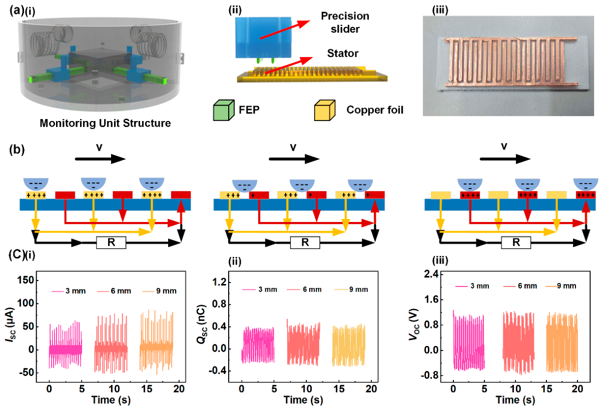
To address the real-time perception demand for relative displacement between bridge piers and girders, a displacement monitoring unit featuring a grating structure is designed. Its structure, working principle, and output characteristics are illustrated in Figure 5. The core structure is depicted in Figure 5a(i): the precision slider is mounted on a guide rail and moves freely along it. An FEP film is attached to the precision slider surface as the electronegative triboelectric layer, while an array of equidistant copper electrodes is arranged on the stator. Centering springs are installed on both sides of the slider to return it to the initial position once the displacement excitation is removed. Figure 5a(ii) shows the relative arrangement of the stator and the precision slider, with an arched FEP film attached to the precision slider to ensure robust contact. Figure 5a(iii) details the interdigital Cu electrode configuration on the stator. This design aims to maximize the effective contact area between the triboelectric layers and enhance the contact pressure via the elastic recovery force of the film, which significantly improves the charge transfer efficiency.
Figure 5b illustrates the charge transfer process of the displacement monitoring unit. As the precision slider drives the FEP film to slide across the copper electrodes, the relative motion between the film and the electrodes induces periodic alternating charge transfer, thereby generating a continuous current signal. The number of peaks in the output electrical signal maintains a linear relationship with the precision slider displacement. By counting these peaks, the real-time displacement between the pier and the girder can be accurately determined, facilitating the identification of the sensing signal. In the structural design, a grating electrode structure (with an electrode width and gap of 1 mm each) is adopted, allowing the precision slider to generate a complete electrical signal cycle for every 2 mm of movement. This configuration enables the high-resolution acquisition of real-time relative displacement information for the bridge structure. This study investigates and compares the response characteristics of voltage, current, and charge signals under a 1 Hz and 10 mm harmonic excitation. As shown in Figure 5c, the measured peak short-circuit current, transferred charge, and open-circuit voltage are 100 μA, 0.7 nC, and 2 V, respectively. To verify the repeatability of these measurements, multiple tests are performed, demonstrating high consistency and reinforcing the reliability of the experimental data. The experimental results demonstrate that the voltage signal exhibits excellent stability and periodic characteristics, with a waveform that effectively tracks the dynamic mechanical displacement. Compared with current and charge signals, the voltage signal provides a superior amplitude response, which facilitates signal feature extraction and processing for subsequent circuitry. Therefore, the open-circuit voltage is identified as the optimal sensing signal for characterizing the relative displacement between pier and girder. These results verify that the THM concurrently performs energy harvesting and displacement sensing under broadband excitation, providing a reliable technical solution for the structural health monitoring of railway bridges.

3.3. Application Demonstration of the THM

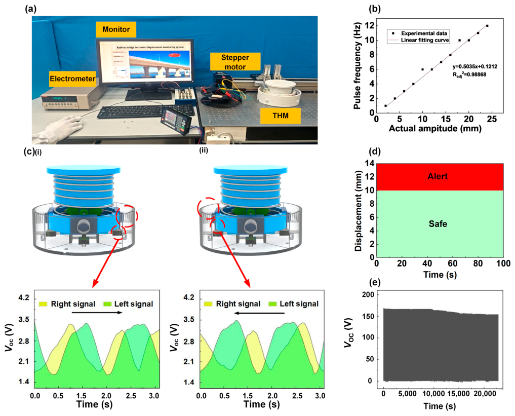
Figure 6 illustrates the experimental characterization and application demonstration of the THM, covering the experimental platform, displacement fitting, direction discrimination, safety warning, and durability assessment. To verify the real-time displacement monitoring capability of the THM, an integrated experimental system is constructed, as shown in Figure 6a. This system comprises the THM prototype and a digital interactive interface, which integrates data visualization with real-time safety monitoring. The interface dynamically presents the motion trajectory and real-time displacement indicators of the bridge pier and girder. Furthermore, the system incorporates a safety threshold-based warning mechanism: when the real-time displacement exceeds the preset threshold, a ‘Warning’ indicator is triggered immediately, demonstrating the high responsiveness and intuitive nature of the displacement monitoring unit. In order to evaluate the monitoring accuracy of the displacement monitoring unit, the number of signal peaks measured by the prototype experiment is linearly fitted with the actual displacement, and the results are shown in Figure 6b. The fitting curve shows a high degree of consistency, and the coefficient of determination (R2) is 0.9886.
The upper shell of the monitoring unit is anchored to the bridge and connected to the slider, while the lower shell, equipped with integrated stator electrodes, is fixed to the pier. By acquiring voltage signals from two distinct units, the system achieves precise identification of displacement vectors, including both displacement magnitude and direction. As illustrated in Figure 6c(i,ii), the motion direction is determined by the phase difference between the two signal sets: when the prototype moves to the right, the right unit reaches the 3.4 V peak first, with the left signal lagging by approximately 0.5 s; conversely, the left unit signal leads during leftward motion. By correlating the signal-triggering sequence with a pulse-counting algorithm, the relative displacement between the pier and the girder can be quantitatively determined. In practical engineering applications, specific risk levels are defined based on bridge displacement, enabling the implementation of corresponding emergency measures. As shown in Figure 6d, the THM system is designed to trigger an alarm once the monitored displacement exceeds 10 mm. Finally, a durability test is conducted to evaluate the long-term reliability of the system under simulated engineering environmental conditions. As presented in Figure 6e, the output voltage decreased from 168 V to 154 V after 20,000 continuous operation cycles, corresponding to a performance retention rate of 91.7%. This marginal voltage attenuation is primarily attributed to the frictional wear at the interfaces. These results confirm the practicability and stability of the THM, providing robust experimental validation for its reliable long-term operation in complex rail transit environments.

4. Conclusions

In this work, an integrated triboelectric vibration energy harvesting and displacement monitoring device (THM) was developed for low-frequency railway bridge vibrations. By incorporating a quasi-zero-stiffness (QZS) mechanism into the energy harvesting unit, efficient low-frequency vibration energy conversion was achieved, enabling enhanced response under bridge vibration conditions. The device delivered an open-circuit voltage of 280 V, a short-circuit current of 28 μA, a transferred charge of 225 nC, and a peak output power of 9 mW. Furthermore, the harvested energy was successfully stored in capacitors and utilized to power low-power electronic devices, demonstrating its potential as a sustainable energy source for distributed bridge monitoring systems. Simultaneously, a freestanding triboelectric sensing unit was developed to monitor the relative displacement between bridge girders and piers. Through voltage signal analysis, the system enabled real-time displacement tracking, displacement-direction identification, and structural safety warning. The monitoring unit exhibited excellent linearity (R2 = 0.9886) and maintained stable performance over 20,000 operation cycles, confirming its reliability for long-term structural monitoring. More importantly, this work demonstrates an integrated strategy for simultaneously utilizing low-frequency railway bridge vibrations as both energy sources and structural information carriers within a unified triboelectric platform. By coupling vibration energy harvesting with structural displacement monitoring, the proposed THM provides a practical route toward self-sustained and intelligent railway bridge health monitoring systems, offering broad prospects for future smart infrastructure applications. Future development of the THM device will focus on optimizing the mechanical and material parameters to further enhance power generation performance. Furthermore, we intend to integrate multi-modal sensing modules into the existing architecture, transforming the THM into a more versatile, self-powered sensing node. This advancement will facilitate the construction of a comprehensive, intelligent monitoring framework for critical infrastructure, ultimately supporting the shift toward fully autonomous and sustainable structural health monitoring systems.

Supplementary Materials

The following supporting information can be downloaded at: https://www.mdpi.com/article/10.3390/inventions11040074/s1, Figure S1: Static analysis diagram of cam and roller; Figure S2. Electric field simulation of TENG unit separation process; Video S1: Power supply demonstration for temperature and humidity sensor; Video S2: Bridge early warning demonstration video.

Author Contributions

Conceptualization, L.M., S.L. and X.L.; Validation, L.M., Z.W., C.L., X.B., S.L. and X.L.; Formal analysis, L.M., Z.W., C.L., X.B., S.L. and X.L.; Investigation, L.M., S.L. and X.L.; Data curation, L.M., Z.W. and X.L.; Writing—original draft, L.M., S.L. and X.L.; Writing—review & editing, L.M., S.L. and X.L.; Project administration, S.L. and X.L.; Funding acquisition, S.L. and X.L. All authors have read and agreed to the published version of the manuscript.

Funding

This research was funded by Educational Department of Liaoning Province grant number JYTMS20231585 and China Postdoctoral Science Foundation grant number 2025M781041.

Data Availability Statement

The original contributions presented in this study are included in the article/Supplementary Material. Further inquiries can be directed to the corresponding authors.

Conflicts of Interest

The authors declare no conflicts of interest.

References

  1. Hu, J.; Fan, C.; Tang, M.; Chen, H.; Pan, H.; Zhang, Z.; Yang, N. Artificial Intelligence enabled self-powered sensing and wind energy harvesting system for bridges monitoring. Nano Energy 2024, 132, 110349. [Google Scholar] [CrossRef]
  2. Li, X.; Zhou, L.; Ma, J.; Wang, C.; Pan, Y.; Chen, Y.; Zhang, D.; He, M. Multi-scale deformation monitoring and characterization of large-span railway bridge by joint satellite/ground-based InSAR and BDS. Measurement 2025, 256, 118199. [Google Scholar] [CrossRef]
  3. Tan, Z.; Gou, H.; Li, W.; Peng, Y.; Wang, J.; Pu, Q.; Bao, Y. Digital twin-based cyber-physical system for intelligent monitoring and predictive operation of long-span high-speed railway arch bridges. Structures 2025, 82, 110609. [Google Scholar] [CrossRef]
  4. He, H.; Bi, R.; Zhao, S.; Wang, M.; Li, X. Influence of environment-induced bridge vibration on high-speed train’s driving performance. J. Vib. Control. 2025, 31, 313–327. [Google Scholar] [CrossRef]
  5. Wang, S.; Wan, X.; Guo, M.; Qiao, H.; Zhang, N.; Ye, Q. Nonlinear Dynamic Analysis of the Wind-Train-Bridge System of a Long-Span Railway Suspension Truss Bridge. Buildings 2023, 13, 277. [Google Scholar] [CrossRef]
  6. Wang, Z.; Hou, L.; He, J.; Yao, M.; Yang, T. Dual-functional triboelectric-electromagnetic hybrid nanogenerator for simultaneous vibration energy harvesting and vibration suppression. Nano Energy 2025, 142, 111277. [Google Scholar] [CrossRef]
  7. Huang, K.; Zhou, Y.; Zhang, Z.; Zhang, H.; Lü, C.; Luo, J.; Shen, L. A real-time quantitative acceleration monitoring method based on triboelectric nanogenerator for bridge cable vibration. Nano Energy 2023, 118, 108960. [Google Scholar] [CrossRef]
  8. Liang, L.; Wang, X.; Li, M.; Wang, Z.; Jiang, M.; Wu, Y.; Zheng, H. Self-powered active vibration sensor by peak-valley data processing independent of the environment toward structural health monitoring. Nano Energy 2023, 117, 108935. [Google Scholar] [CrossRef]
  9. Li, M.; Zhang, Y.; Li, K.; Zhang, Y.; Xu, K.; Liu, X.; Zhong, S.; Cao, J. Self-powered wireless sensor system for water monitoring based on low-frequency electromagnetic-pendulum energy harvester. Energy 2022, 251, 123883. [Google Scholar] [CrossRef]
  10. Meng, L.; Kong, X.; Meng, J.; Liu, S.; Bi, X. Self-Powered in Situ Monitoring Device for Capturing the Vibration Energy of Bridges. ACS Appl. Electron. Mater. 2026, 8, 3423–3432. [Google Scholar] [CrossRef]
  11. Zhu, Z.; Wang, Z.; Dai, K.; Wang, X.; Zhang, H.; Zhang, W. An adaptive and space-energy efficiency vibration absorber system using a self-sensing and tunable magnetorheological elastomer. Nano Energy 2023, 117, 108927. [Google Scholar] [CrossRef]
  12. Xu, H.; Tao, J.; Liu, Y.; Mo, Y.; Bao, R.; Pan, C. Fully Fibrous Large-Area Tailorable Triboelectric Nanogenerator Based on Solution Blow Spinning Technology for Energy Harvesting and Self-Powered Sensing. Small 2022, 18, 2202477. [Google Scholar] [CrossRef] [PubMed]
  13. Masabi, S.N.; Fu, H.; Theodossiades, S. A Multi-Stable Rotational Energy Harvester Using a Rolling Sphere and Magnetic Coupling for Ultra-Low Frequency Motions. In Proceedings of the 2022 21st International Conference on Micro and Nanotechnology for Power Generation and Energy Conversion Applications (PowerMEMS), Salt Lake City, UT, USA, 12–15 December 2022; pp. 102–105. [Google Scholar] [CrossRef]
  14. Rosso, M.; Kohtanen, E.; Corigliano, A.; Ardito, R.; Erturk, A. Dynamical Behavior of Frequency up-Converted Piezoelectric Vibration Energy Harvesters at Different Velocities of Magnetic Interaction. In Proceedings of the 2022 21st Inter national Conference on Micro and Nanotechnology for Power Generation and Energy Conversion Applications (PowerMEMS), Salt Lake City, UT, USA, 12–15 December 2022; pp. 260–263. [Google Scholar] [CrossRef]
  15. Sheng, C.; Xiang, X.; Shen, H.; Song, R. A novel rope-driven piezoelectric energy harvester for multidirectional vibrations. Energy Rep. 2023, 9, 3553–3562. [Google Scholar] [CrossRef]
  16. Shi, G.; Peng, Y.; Tong, D.; Chang, J.; Li, Q.; Wang, X.; Xia, H.; Ye, Y. An ultra-low frequency vibration energy harvester with zigzag piezoelectric spring actuated by rolling ball. Energy Convers. Manag. 2021, 243, 114439. [Google Scholar] [CrossRef]
  17. Liu, D.; Luo, J.; Huang, L.; Chen, M.; Ji, M.; Wang, Z.; Kang, J. Triboelectric nanogenerators as a practical approach for wind energy harvesting: Mechanisms, designs, and applications. Nano Energy 2025, 136, 110767. [Google Scholar] [CrossRef]
  18. Jarvio-Cordova, V.; Elvira-Hernández, E.; García-Saldaña, A.; Garay-Marín, J.; Ovando-Chacón, G.; Diaz-González, M.; Delgado-Alvarado, E.; Mora-Aquino, G.; Herrera-May, A. Sustainable triboelectric nanogenerator based on recycled and waste materials for renewable energy harvesting. Renew. Energy 2025, 251, 123439. [Google Scholar] [CrossRef]
  19. Elvira-Hernández, E.; Hernández-Hernández, J.; de León, A.; Gallardo-Vega, C.; Delgado-Alvarado, E.; López-Huerta, F.; Herrera-May, A. Green energy harvesting to power electronic devices using portable triboelectric nanogenerator based on waste corn husk and recycled polystyrene. Energy Rep. 2024, 11, 276–286. [Google Scholar] [CrossRef]
  20. Li, J.; Yin, J.; Guo, W. Hydrovoltaic energy and intelligence: Where ions meet electrons. Iontronics 2025, 1, 3. [Google Scholar] [CrossRef]
  21. Wang, Y.; Wang, Y.; Liu, X.; Wang, X.; Dai, K.; You, Z. Self-Powered Microsystem for Ultra-Fast Crash Detection via Prestressed Triboelectric Sensing. Research 2025, 8, 0753. [Google Scholar] [CrossRef] [PubMed]
  22. Wang, Z. Triboelectric Nanogenerator (TENG)-Sparking an Energy and Sensor Revolution. Adv. Energy Mater. 2020, 10, 2000137. [Google Scholar] [CrossRef]
  23. Shan, C.; He, W.; Wu, H.; Fu, S.; Li, K.; Liu, A.; Du, Y.; Wang, J.; Mu, Q.; Liu, B.; et al. Dual Mode TENG with Self-Voltage Multiplying Circuit for Blue Energy Harvesting and Water Wave Monitoring. Adv. Funct. Mater. 2023, 33, 2305768. [Google Scholar] [CrossRef]
  24. Liu, J.; Wang, Z.; Wang, S.; Zhang, Y.; Li, W.; Zhao, S.; Li, D.; Wu, Y.; Guo, H.; Zheng, H. Achieving 87% of Theoretical Output Charge Density by Optimizing Charge Behaviors in Polydimethylsiloxane/CaCu3Ti4O12-Based Triboelectric Nanogenerators. Research 2025, 8, 0921. [Google Scholar] [CrossRef] [PubMed]
  25. Cao, X.; Wei, X.; Huo, X.; Wang, B.; Hu, Y.; Wang, Z.; Wu, Z. Self-powered retractable reel sensor for crack monitoring and warning in civil infrastructures. Chem. Eng. J. 2023, 478, 147238. [Google Scholar] [CrossRef]
  26. Wang, X.; Zhao, N.; Guo, Y.; Zhang, Z. Hydrogel diodes towards future iontronics devices. Iontronics 2026, 2, 19. [Google Scholar] [CrossRef]
  27. Li, X.; Wang, Z.L.; Wei, D. Iontronic logic control driven by dynamic electrical double layer regulation. Iontronics 2025, 1, 2. [Google Scholar] [CrossRef]
  28. Zhao, Y.; Feng, Y.; Gao, Q.; Li, H.; Guo, X.; Wang, J.; Wang, X.; Dong, L.; Yu, Y.; Wang, Z.; et al. Boosting Output Performance of Triboelectric Nanogenerator via Interface Self-Regulation Strategy. Research 2025, 8, 0906. [Google Scholar] [CrossRef] [PubMed]
  29. Li, Q.; Fu, S.; Yang, H.; Li, X.; Zhang, X.; Hu, C.; Xi, Y. Achieving Ultrahigh DC-Power Triboelectric Nanogenerators by Lightning Rod-Inspired Field Emission Modeling. Research 2024, 7, 0437. [Google Scholar] [CrossRef] [PubMed]
  30. Wang, B.; Zhao, H.; Jin, C.; Xu, Y.; Ding, W. Ionic-electrostatic modeling of solid-liquid triboelectric nanogenerators. Iontronics 2026, 2, 17. [Google Scholar] [CrossRef]
  31. Wang, W.; Yin, N.; Wu, Z.; Zhang, Z. Omnidirectional energy harvesting with 3D-TENG for vibration diagnosis. Chem. Eng. J. 2025, 509, 161022. [Google Scholar] [CrossRef]
  32. Basaran, S. Hybrid energy harvesting system under the electromagnetic induced vibrations with non-rigid ground connection. Mech. Syst. Signal Process. 2022, 163, 108198. [Google Scholar] [CrossRef]
  33. Shi, G.; Zeng, W.; Xia, Y.; Xa, J.; Jin, S.; Li, Q.; Wang, X.; Xia, H.; Ye, Y. A floating piezoelectric electromagnetic hybrid wave vibration energy harvester actuated by a rotating wobble ball. Energy 2023, 270, 126808. [Google Scholar] [CrossRef]
  34. Chen, T.; Wang, K.; Cheng, L.; Pan, H.; Cui, H.; Zhou, J. Theoretical and experimental research on a Quasi-Zero-Stiffness-Enabled nonlinear piezoelectric energy harvester. Commun. Nonlinear Sci. Numer. Simul. 2024, 133, 107863. [Google Scholar] [CrossRef]
  35. Guo, W.; Long, Y.; Bai, Z.; Wang, X.; Liu, H.; Guo, Z.; Tan, S.; Guo, H.; Wang, Y.; Miao, Y. Variable stiffness triboelectric nano-generator to harvest high-speed railway bridge’s vibration energy. Energy Convers. Manag. 2022, 268, 115969. [Google Scholar] [CrossRef]
  36. Meng, L.; Zhang, W.; Wang, S.; Zhang, X.; Li, H.; Liu, S.; Cheng, X. Damping Structured Triboelectric Nanogenerator for Stay Cables Vibration Energy Graded Harvesting. Energy Technol. 2024, 12, 2400048. [Google Scholar] [CrossRef]
  37. Kondo, Y.; Achouri, N.; Al Falou, H.; Atar, L.; Aumann, T.; Baba, H.; Boretzky, K.; Caesar, C.; Calvet, D.; Chae, H.; et al. First observation of 28O. Nature 2023, 623, E13. [Google Scholar] [CrossRef] [PubMed]
  38. Yu, H.; He, X.; Ding, W.; Hu, Y.; Yang, D.; Lu, S.; Wu, C.; Zou, H.; Liu, R.; Lu, C.; et al. A Self-Powered Dynamic Displacement Monitoring System Based on Triboelectric Accelerometer. Adv. Energy Mater. 2017, 7, 1700565. [Google Scholar] [CrossRef]
  39. Xu, J.; Wei, X.; Li, R.; Kong, S.; Wu, Z.; Wang, Z. A Capsule-Shaped Triboelectric Nanogenerator for Self-Powered Health Monitoring of Traffic Facilities. ACS Mater. Lett. 2022, 4, 1630–1637. [Google Scholar] [CrossRef]
  40. Fan, Y.; Zhang, X.; Cheng, E.; Qin, C.; Qin, N.; Wu, J.; Guo, X.; Chen, H.; Guo, T. 1D in-situ convolution system based on vibration signal for real-time structural health monitoring. Nano Energy 2024, 127, 109694. [Google Scholar] [CrossRef]
  41. Zhang, W.; Zhang, X.; Yu, Y.; Cheng, X.; Li, H.; Liu, S.; Meng, L.; Wang, Z.; Cheng, T. Self-Powered Intelligent Damper Integrated Triboelectric-Electromagnetic Hybrid Unit for Vibration In Situ Monitoring of Stay Cables. Adv. Energy Mater. 2023, 13, 2302838. [Google Scholar] [CrossRef]
  42. Tan, D.; Zhou, J.; Wang, K.; Zhao, X.; Wang, Q.; Xu, D. Bow-type bistable triboelectric nanogenerator for harvesting energy from low-frequency vibration. Nano Energy 2022, 92, 106746. [Google Scholar] [CrossRef]
  43. Zhang, H.; Huang, K.; Zhou, Y.; Sun, L.; Zhang, Z.; Luo, J. A real-time sensing system based on triboelectric nanogenerator for dynamic response of bridges. Sci. China-Technol. Sci. 2022, 65, 2723–2733. [Google Scholar] [CrossRef]
Figure 1. Structure and working principle of the railway bridge vibration energy harvesting and displacement monitoring device: (a) Application scenario and installation location of the THM; (b) (i) structural composition and (ii) working principle of the energy harvesting unit; (c) (i) structural composition and (ii) sensing principle of the monitoring unit.
Inventions 11 00074 g001
Figure 2. Structural design and mechanical analysis of the THM energy harvesting system. (a) (i) Energy harvesting process and (ii) schematic diagram of the contact-separation working mode. (b) (i) Static mechanical analysis of the roller-cam mechanism, (ii) dimensionless force-displacement characteristics, and (iii) time-displacement response of the system. (c) (i) Dynamic mechanical analysis of the roller-cam mechanism, (ii) dimensionless stiffness-displacement characteristics, and (iii) frequency response spectrum.
Inventions 11 00074 g002
Figure 3. Output performance characterization of the THM under various excitation frequencies and spring stiffnesses. (a) Influence of excitation frequency on (i) short-circuit current, (ii) transferred charge, and (iii) open-circuit voltage at a wire diameter of 0.8 mm. (b) Influence of spring wire diameter on (i) short-circuit current, (ii) transferred charge, and (iii) open-circuit volage at a frequency of 2.5 Hz. (c) Three-dimensional mapping of (i) short-circuit current, (ii) transferred charge, and (iii) open-circuit voltage under various combinations of excitation frequency and spring wire diameter.
Inventions 11 00074 g003
Figure 4. Output performance characterization of the THM under continuous variable–frequency and variable–amplitude excitation. (a) Schematic diagram of the THM installation. (b) Energy harvesting performance: (i) charging curves for different capacitors, and (ii) dependence of short–circuit current and peak power on external load resistance. (c) Output characteristics under Working condition 1: (i) excitation profile, (ii) short–circuit current, and (iii) transferred charge. (d) Output characteristics under Working condition 2: (i) excitation profile, (ii) short–circuit current, and (iii) transferred charge.
Inventions 11 00074 g004
Figure 5. Structure, working principle, and output performance of the THM displacement monitoring unit. (a) Structural design: (i) schematic of the monitoring unit, (ii) relative arrangement of the stator and precision slider, and (iii) photograph of the interdigital stator electrodes. (b) Schematic diagram of the charge transfer mechanism. (c) Output response under various excitation amplitudes: (i) short-circuit current, (ii) transferred charge, and (iii) open-circuit voltage.
Inventions 11 00074 g005
Figure 6. Experimental characterization and application demonstration of the RB-VECM displacement sensing system. (a) Photograph of the experimental test platform. (b) Correlation between the measured displacement and the actual displacement. (c) Real-time voltage signals demonstrating phase differences for different motion directions: (i) rightward shift and (ii) leftward shift. (d) Interface for setting the security warning threshold. (e) Durability test results of the monitoring unit under continuous operation.
Inventions 11 00074 g006
Disclaimer/Publisher’s Note: The statements, opinions and data contained in all publications are solely those of the individual author(s) and contributor(s) and not of MDPI and/or the editor(s). MDPI and/or the editor(s) disclaim responsibility for any injury to people or property resulting from any ideas, methods, instructions or products referred to in the content.