1. Introduction
The increasing pressure to meet international climate commitments and decarbonization targets has significantly intensified research into sustainable aviation solutions, particularly alternative fuels aimed at reducing the environmental footprint of aerospace propulsion systems while maintaining operational performance and safety requirements [
1,
2,
3,
4,
5]. Among these, fuels derived from the pyrolysis of plastic waste have emerged as a promising option, offering potential benefits in terms of resource recovery and diversification of non-fossil fuel pathways [
6,
7,
8,
9]. However, the qualification of such fuels for aerospace applications necessitates dedicated experimental platforms capable of enabling systematic, repeatable, and safe investigations of combustion behavior, engine performance, and emission characteristics under controlled laboratory conditions [
6,
9,
10].
Current research infrastructures for gas turbine and alternative fuel testing are largely focused on full-scale engine assessment or emission measurements under narrowly defined conditions [
6,
9,
10,
11]. Prior art demonstrates various specialized platforms that address specific aspects of engine operation: CN115876480A [
12] discloses a test platform for aircraft engines that enables exhaust gas analysis under simulated high-altitude conditions; CN216748568U [
13] provides a system for high-pressure and high-temperature gas sampling directly from combustion chambers; CN114671047B [
14] presents a multi-channel ignition test device for evaluating the behavior of ignition systems with different fuel mixtures; CN202372352U [
15] describes a dual-engine emission testing setup that allows simultaneous evaluation of emissions from two engines using independent full-flow sampling lines; and CN119438116A [
16] introduces an airborne system for detecting and analyzing atmospheric gas fluxes using a UAV-mounted multi-module sensor array. While these systems provide valuable insights for their respective purposes, they are typically characterized by high structural and operational complexity, stringent synchronization requirements, and substantial costs, which limit their flexibility and accessibility for modular, laboratory-scale experimentation. Furthermore, most existing platforms address isolated components, such as emissions monitoring, ignition, or flow analysis, without enabling integrated, correlated evaluation of combustion dynamics, fuel properties, and overall propulsion performance within a single, flexible research installation [
12,
13,
14,
15,
16].
To overcome the identified limitations of existing testing solutions for sustainable fuels, the present work brings into the light a modular experimental testing installation specifically conceived for the evaluation of alternative fuels obtained from plastic waste pyrolysis. The proposed installation is configured as a small-scale gas turbine representative of a jet engine, integrating all functional subsystems required for autonomous and safe operation under laboratory conditions. In contrast to prior art systems addressing isolated testing functions, the installation enables continuous, correlated assessment of combustion quality through real-time exhaust gas analysis, high-speed flame visualization, and comprehensive measurement of key thermodynamic and mechanical parameters, including temperatures, pressures, rotational speed, mass flow rates, and thrust. The main objective of the study is to validate the feasibility, flexibility, and operational reliability of the modular installation as an innovative research platform for systematic, repeatable, and comparative evaluation of alternative aerospace fuels, thereby contributing to the advancement of experimental methodologies in sustainable propulsion research.
2. Materials and Methods
2.1. Modular Testing Facility Architecture
This study is centered on the design and implementation of a modular testing facility developed for the evaluation of sustainable fuels obtained from plastic waste pyrolysis for aerospace engine applications. The facility is conceived as an integrated small-scale gas turbine system representative of a jet engine and is intended to serve as a flexible experimental platform rather than a dedicated engine performance test rig. All functional subsystems are integrated into a modular assembly mounted on a mobile frame, enabling autonomous, safe operation under controlled laboratory conditions and facilitating rapid reconfiguration and maintenance.
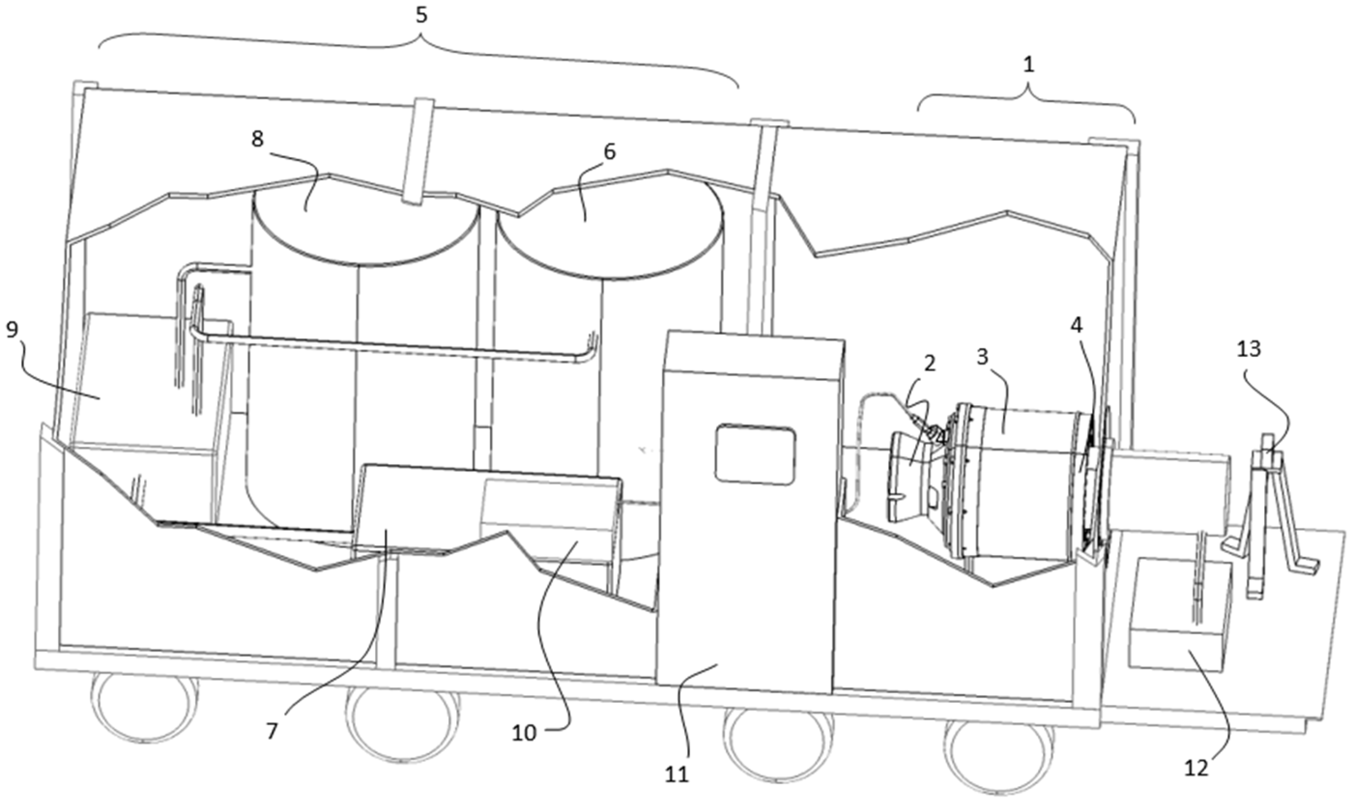
The installation (
Figure 1) is configured as a modular system integrating three main subsystems. The first subsystem is the micro gas turbine engine (1), which incorporates the compressor (2) responsible for compressing the air required for the combustion process. The second integrated element is the combustion chamber (3), where the air–fuel mixture is burned and chemical energy is converted into thermal energy. The final integrated element is the turbine (4), which converts the energy of the combustion gases into mechanical work and thrust.
An alternative fuel supply is provided through a dedicated fueling system (5), which includes a fuel tank (6), a Stirling engine (7) attached to the tank for temperature control of the alternative fuel, an additional tank (8) for the reference fuel, electronically controlled pumping components (9), and a lubricant additive for protecting the bearings of the common shaft. The start-up and ignition process is fully automated, using an initial electric drive system (10) to ensure stable combustion initiation.
Monitoring and operational control are achieved through a command and data acquisition system (11), which enables measurement and recording of key parameters such as temperatures, rotational speed, pressures, mass flow rates, and thrust, with real-time analysis capability. The combustion process is continuously evaluated using an exhaust gas analysis system (12), employed to determine the composition and combustion quality of the fuel mixtures. In addition, combustion stability during experiments is monitored with the aid of a high-speed camera (13), operating at 50,000 fps with a resolution of 1024 × 1024 pixels.
Subsystem 11 integrates the command and data acquisition functions of the installation into a single interface, allowing real-time monitoring and manual adjustment of all operational parameters during test runs. The panel displays live values for rotational speed (n), compressor inlet temperature (T
2), turbine outlet temperature (T
3), fuel volumetric flow rate (Qc), air mass flow rate (Qa), compressor pressure ratio (πc), and thrust (F), and logs all channels simultaneously via the integrated DAQ system. Target rotational speed and fuel flow setpoints are entered through the control interface, which also manages the automated ignition sequence (electric starter, butane pilot, glow plug). All data are exportable for post-processing and comparative analysis across test regimes. The key technical parameters and measurement channels of the ET 796 experimental module are presented in
Table 1.
The energy conversion module consists of a compressor, an annular-type combustion chamber, and a turbine mounted on a common shaft. This configuration enables controlled compression of intake air, combustion of air–fuel mixtures, and conversion of thermal energy into mechanical work and thrust. The modular design allows direct access to individual components, supporting systematic investigation of fuel-related effects while minimizing structural complexity.
To validate this concept, a model-scale gas turbine system, designated as the experimental module ET 796, was employed as a representative example of the proposed modular testing facility. The ET 796 module is a complete gas turbine system designed for the investigation of operating behavior and performance characteristics at model scale and is mounted on a mobile frame equipped with rollers. The assembly integrates all subsystems required for autonomous operation, including the turbine unit, fuel supply system, start-up and ignition system, and a control and data acquisition panel, thereby providing a suitable platform for validating the modular architecture and diagnostic capabilities of the testing facility [
17].
The core of the ET 796 module is a JetCat P80 reaction turbine (Ingenieurbüro CAT, M. Zipperer GmbH, Ballrechten-Dottingen, Germany), which integrates a radial compressor, an annular combustion chamber, and an axial turbine mounted on a common shaft. During operation, intake air is compressed, mixed with fuel, vaporized, and ignited within the combustion chamber, while the resulting combustion gases expand through the turbine to generate thrust. The turbine is capable of reaching rotational speeds of up to 116,000 rpm, allowing evaluation of the testing facility under high-speed operating conditions representative of small-scale aerospace propulsion systems.
Fuel delivery within the ET 796 module is provided by an electronically controlled electric pump connected to a dedicated fuel tank, along with a fast-acting safety valve and an auxiliary fuel valve. The fuel used consists of a kerosene–synthetic oil mixture in a 20:1 ratio, ensuring adequate lubrication of the shaft bearings during operation. This configuration supports stable fuel flow and safe operation while enabling assessment of the facility’s capability to handle liquid fuel mixtures under controlled conditions.
The start-up and ignition process is fully automated and is achieved using an electric starter motor equipped with a conical clutch, an auxiliary butane fuel supply controlled by a solenoid valve, and a glow plug for ignition. This automated sequence allows repeatable and reliable initiation of combustion, serving to validate the integration of the start-up and control subsystems within the modular testing facility.
Operational monitoring and data acquisition are performed through a control panel that integrates real-time displays for compressor, combustion chamber, and turbine temperatures; rotational speed; combustion chamber pressure; air and fuel mass flow rates; and generated thrust. The system also includes a computer interface port, enabling graphical visualization and recording of operating parameters in real time. All components are mounted on a dedicated test bench, with fuel lines and the auxiliary gas cylinder positioned beneath the structure, while built-in protection mechanisms against overspeed and overheating ensure safe operation throughout experimental validation [
17].
2.2. Fuel Handling and Conditioning Subsystem
The testing installation incorporates a dedicated fuel handling subsystem specifically engineered to support the safe, repeatable, and flexible evaluation of both alternative fuels derived from plastic waste pyrolysis and conventional reference fuels. The subsystem includes a primary fuel tank equipped with an attached Stirling engine for thermal conditioning of the alternative fuel mixture, ensuring stable temperature and flow properties during operation. A secondary tank is provided for reference fuel supply, enabling comparative testing without hardware reconfiguration. Fuel delivery is managed by electronically controlled pumping elements and safety devices, while a lubricant additive is mixed with the alternative fuel to protect the bearings of the common shaft and to enhance operational stability. Dedicated fuel supply architectures of this type are widely recognized as essential in experimental gas turbine test benches, where accurate control of fuel properties and delivery conditions is required to ensure reproducible combustion and performance assessment [
18]. The subsystem includes a primary fuel tank designed for alternative-fuel operation, equipped with an attached Stirling engine for thermal conditioning of the fuel mixture. Active thermal conditioning of alternative fuels is commonly employed to stabilize temperature-dependent properties such as viscosity and density, thereby ensuring consistent mass flow, improved atomization, and reduced variability in combustion behavior during experimental testing [
19].
To enable direct comparative investigations without mechanical reconfiguration of the installation, a secondary fuel tank is integrated for the supply of a reference fuel. Multi-branch and dual-fuel supply configurations are commonly implemented in gas turbine test systems to support different fuel pathways while maintaining stable fuel delivery and comparable operating conditions, thereby improving reliability in comparative analyses (e.g., fuel supply systems designed with multiple functional branches, flow circuits, and purge capabilities) [
20]. In such systems, independent fuel branches with valves and flow regulation components are used to control and switch between fuels, stabilizing delivery under varied operating parameters and enhancing overall test rig flexibility [
21]. Similarly, dual-fuel supply architectures incorporating buffer tanks, branch paths, and controlled interfaces demonstrate how multiple fuel types can be managed within a single turbine test context, supporting rapid fuel selection without hardware changes [
22]. Fuel delivery from both tanks is managed through electronically controlled pumping elements, which provide accurate regulation of fuel flow rate and pressure across the operating envelope. The fuel circuit further incorporates fast-acting safety and shut-off devices, consistent with established aerospace fuel supply engineering practices that emphasize controlled flow, modular design, and safety compliance under test conditions [
23].
To ensure mechanical reliability and stable long-duration operation of the rotating assembly, a lubricant additive is mixed with the alternative fuel prior to injection. The use of fuel–lubricant mixtures or fuel-borne lubrication systems has been documented for miniature and small gas turbine engines, where specific additives are introduced into the fuel stream to provide lubrication to high-speed bearings and reduce frictional wear, thereby enhancing bearing life and reducing maintenance intervals [
24]. Experimental operability studies of air–fuel lubrication systems demonstrate that fuel or air–fuel mixtures can be used to deliver lubricant to turbine rotor bearings, contributing to bearing function across a wide range of operating conditions [
25]. Similarly, research on small gas turbine test stands shows that liquid fuels blended with oil additives (e.g., Jet A-1 with an added lubricant) can be successfully employed to provide lubrication for bearing assemblies without adversely affecting overall engine operation or combustion parameters [
26]. The integration of fuel conditioning, controlled delivery, safety mechanisms, and lubrication within a single subsystem enhances operational stability, measurement repeatability, and experimental efficiency. Consequently, the fuel handling subsystem plays a key role in validating the testing facility as a reliable and versatile experimental platform for laboratory-scale evaluation of sustainable aerospace fuels under controlled conditions.
Table 2 summarizes the requirements that hydrocarbon fractions must satisfy in order to be evaluated within the modular facility, derived from the operational constraints of the JetCat P80 turbine [
17], the experimental observations of the present study, and the physicochemical characterization of polyethylene and polypropylene pyrolysis oils reported in [
9].
2.3. Start-Up, Ignition, and Control Strategy
Start-up and ignition are fully automated and implemented through an initial electric drive system, an auxiliary fuel source, and an ignition element, ensuring repeatable and safe initiation of combustion; similar structured automatic start sequences and control logic have been documented for turbine test benches, where automated control sequences advance the engine from motoring to stable combustion under monitored conditions (e.g., automated start process with prescribed fuel and air control phases) [
27]. Facility operation is supervised by an integrated command and data acquisition system that enables real-time monitoring and recording of characteristic parameters, including temperatures, pressures, rotational speed, mass flow rates, and thrust, which are essential components of automated gas turbine test control systems where measured operating parameters are continuously collected and managed to adjust control actions during engine start-up and transient regimes [
28,
29]. For example, automated gas turbine test systems integrate sequences and sensor feedback into a single control/data acquisition framework that logically executes test cycles and compares measured performance against predefined sequences, ensuring safe cutting-off of fuel or modulating ignition as needed [
28]. This architecture allows rapid adaptation to different fuel formulations while preserving experimental consistency and operational safety, aligning with established practices for test rigs where closed-loop control and real-time data acquisition are fundamental to reproducible and safe engine experimentation [
29].
2.4. Diagnostic and Monitoring Systems
Combustion diagnostics are integrated into the testing facility to enable continuous assessment of combustion quality and stability, a practice that aligns with advanced diagnostic methodologies used in modern combustion research rigs. Real-time monitoring of exhaust gas composition using dedicated analysis systems allows researchers to quantify reactant consumption, product formation, and emission trends during engine operation, including major species such as CO
2, CO, NOx, and unburned hydrocarbons, thereby providing a comprehensive overview of combustion efficiency and pollutant generation (e.g., FTIR gas analysis for combustion research) [
30].
Within the currently prototyped configuration of the installation, exhaust gas analysis is performed using the MRU NOVAplus EMI portable multifunction flue gas analyzer (MRU Instruments, Humble, TX, USA), a TUV-certified and MCERTS-certified instrument (Sira Certificate No. MC200366/00) designed for industrial combustion emission monitoring. The analyzer simultaneously measures up to eight exhaust gas components by combining two complementary measurement principles: non-dispersive infrared spectroscopy (NDIR) for CO
2 quantification, and electrochemical sensing (EC) for O
2, CO, NO, NO
2, and SO
2 detection. This dual-technology approach ensures reliable analysis across a wide concentration range, from trace-level emission species to major combustion products, and is well suited to the variable operating conditions encountered across the tested rotational regimes (35,000–90,000 rpm). The analyzer is equipped with an automatic zeroing function, enabling long-term measurement campaigns without manual recalibration drift, and integrates an internal data logger with SD card and USB output for synchronized recording of emission data alongside the thermodynamic parameters acquired by the command and data acquisition system (subsystem 11) [
31]. The measurement specifications of the MRU NOVAplus EMI exhaust gas analyzer for the species reported in this study are listed below, in
Table 3.
The measurement ranges and certified accuracy values listed in
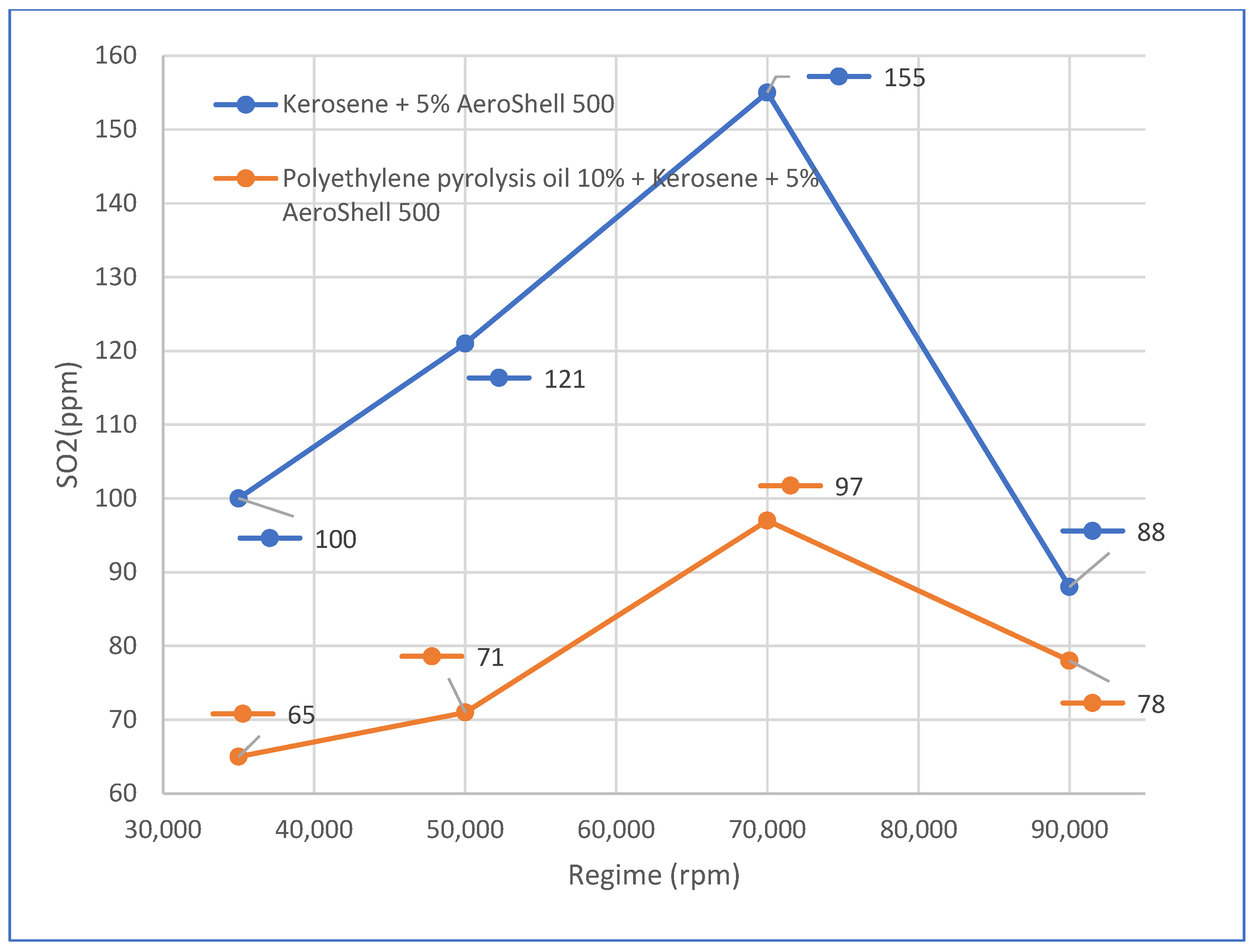
Table 1 confirm that the analyzer is suitable for the emission levels recorded in this study: CO values in the range 2139–4232 ppm (well within the 0–10,000 ppm EC range), SO
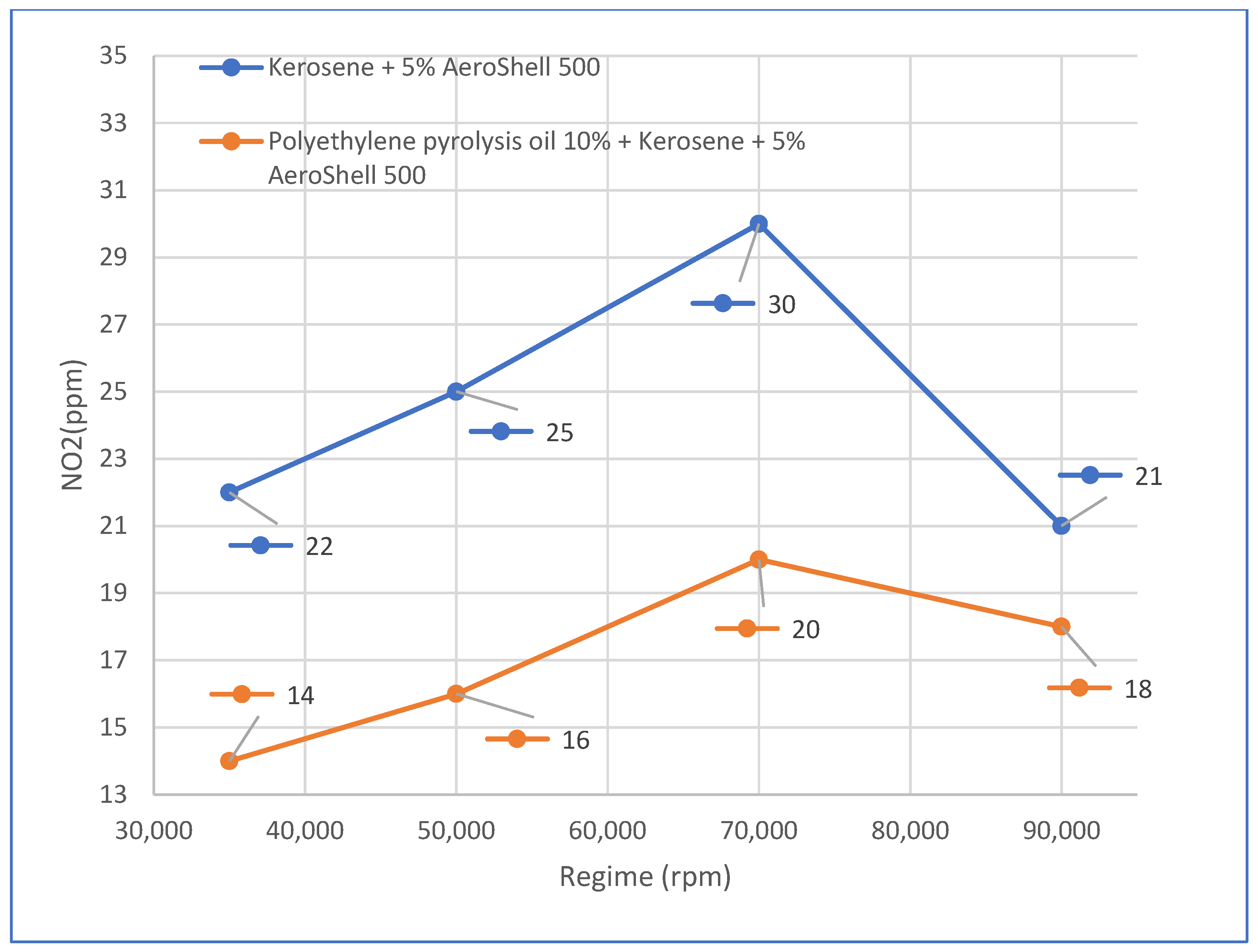
2 values of 51–155 ppm (within the 0–2000 ppm range), and NO
2 values of 14–30 ppm (within the 0–200 ppm range). The stated accuracy of ±5 ppm or 5% of reading for NO and NO
2 and ±10 ppm or 5% of reading for SO
2 is sufficient to resolve the fuel-dependent emission differences observed between the reference blend and the pyrolysis oil-containing mixtures. The CO
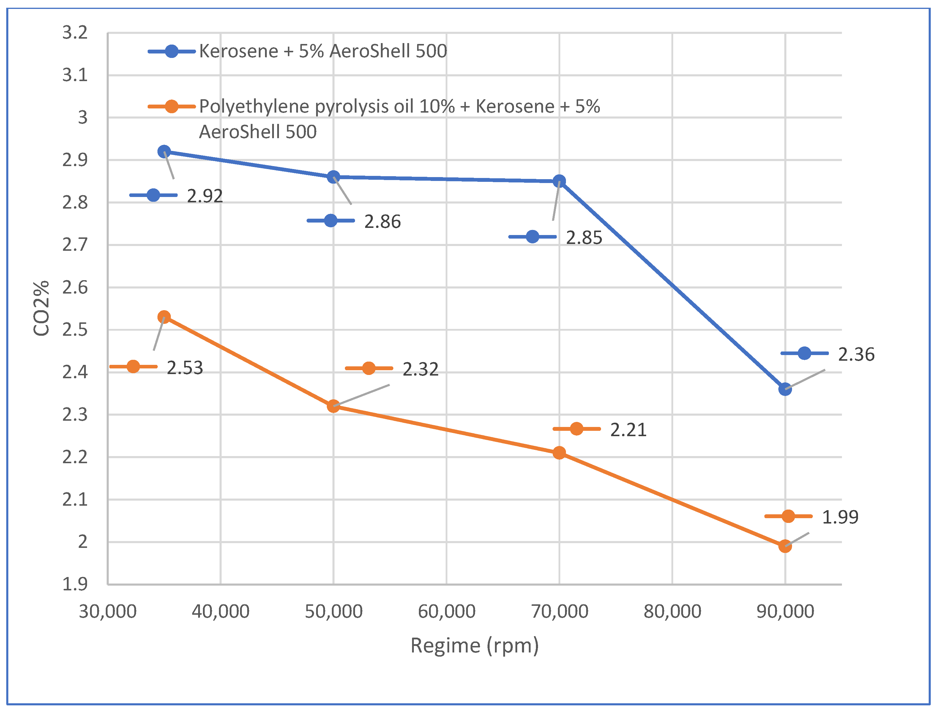
2 NDIR channel, with an accuracy of ±0.3 vol% or 5% of reading over a 0–40 vol% range, provides reliable quantification of the 1.99–2.92 vol% CO
2 concentrations recorded across all tested regimes [
31].
In addition to chemical diagnostics, flame stability and dynamic combustion behavior are investigated using high-speed optical imaging systems: advanced high-speed cameras and laser-based techniques are widely used to capture transient flame structures, propagation dynamics, and turbulent combustion phenomena at high temporal resolution, enabling correlated analysis of combustion events [
32,
33]. High-speed camera systems with frame rates comparable to those used in the present facility (tens of kHz to beyond) are routinely employed in combustion research to visualize flame fronts, detect instabilities, and support validation of combustion models, linking optical observations with measured gas species concentrations and thermal conditions [
33]. The combined diagnostic approach of real-time exhaust analysis and high-speed imaging supports a correlated analysis of fuel behavior and system response within a single experimental framework, enhancing both the understanding of combustion dynamics and the reliability of comparative evaluations of alternative fuels.
2.5. Experimental Validation and Data Availability
To validate the functionality and reliability of the proposed testing facility, experimental runs were conducted using alternative fuel mixtures derived from plastic waste pyrolysis and a reference fuel. These experiments were intended to demonstrate stable operation, effective subsystem integration, and the capability of the facility to support repeatable and comparative fuel evaluations, rather than to optimize engine performance.
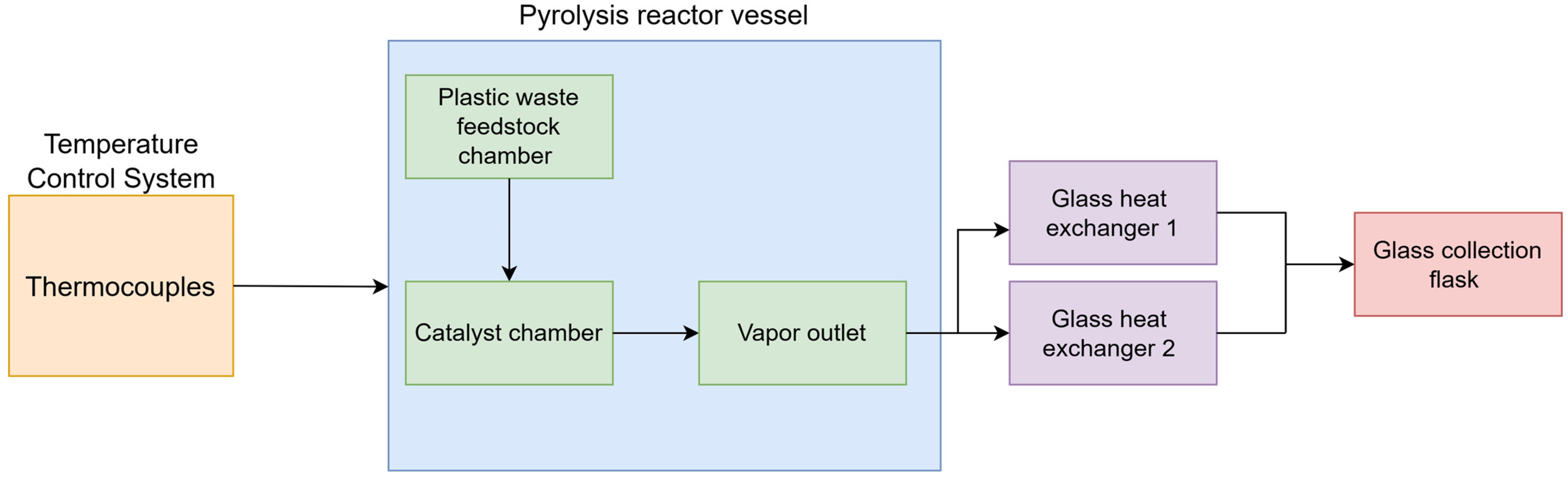
The pyrolysis oil used in the alternative fuel blends was produced using a dedicated pyrolysis installation specifically designed for the thermochemical conversion of plastic waste into high-energy-value products. The installation comprises four integrated functional subsystems. The temperature control panel enables real-time monitoring and precise regulation of temperatures across the installation, particularly within the pyrolysis reactor vessel, via thermocouples connected to the reactor body; rigorous temperature control is essential for maintaining the thermal regime required for polymer decomposition and for directing product formation. The reactor vessel itself features a compartmentalized internal structure: the first compartment accommodates the plastic waste feedstock subjected to thermal treatment, while the second compartment, the catalyst chamber, houses the catalyst used during the reaction, whose presence can significantly influence both the yield and the composition of the condensable liquid fraction. A condensation system, comprising two glass heat exchangers, ensures the transition of pyrolysis vapors from the gas phase to the liquid phase through controlled cooling; efficient operation of this subsystem is critical for the recovery of condensable fractions from the product gas stream. Finally, a glass collection flask, resistant to elevated temperatures and reactive chemical species, accumulates the liquid product obtained after condensation. The entire installation operates as an integrated system, enabling experiments to be conducted under controlled, reproducible conditions adaptable to different reaction parameters and plastic waste feedstock types. The process flow diagram of the prototype pyrolysis reactor system is illustrated in
Figure 2.
Fuel mixtures were prepared prior to testing using a high-precision analytical balance to ensure accurate dosing of each component, as well as a magnetic stirrer to achieve efficient homogenization of the involved phases. During the mixing process, each fuel blend was subjected to mild heating in order to facilitate the dissolution and dispersion of a solid suspension that formed within the alternative fuel. This suspension represented an undesirable effect associated with the absence of a distillation stage in the pyrolysis-derived-fuel production process, leading to the presence of residual solid fractions. The adopted preparation procedure ensured improved mixture uniformity and enhanced repeatability of the experimental conditions during subsequent combustion and performance evaluations within the modular testing installation.
Kerosene blends containing pyrolysis products obtained from polypropylene were considered suitable for experimental testing, as they did not exhibit solid suspension within the liquid phase, although their appearance remained slightly turbid. The adopted preparation procedure ensured improved mixture uniformity and enhanced repeatability of the experimental conditions during subsequent combustion and performance evaluations within the modular testing installation.
3. Results
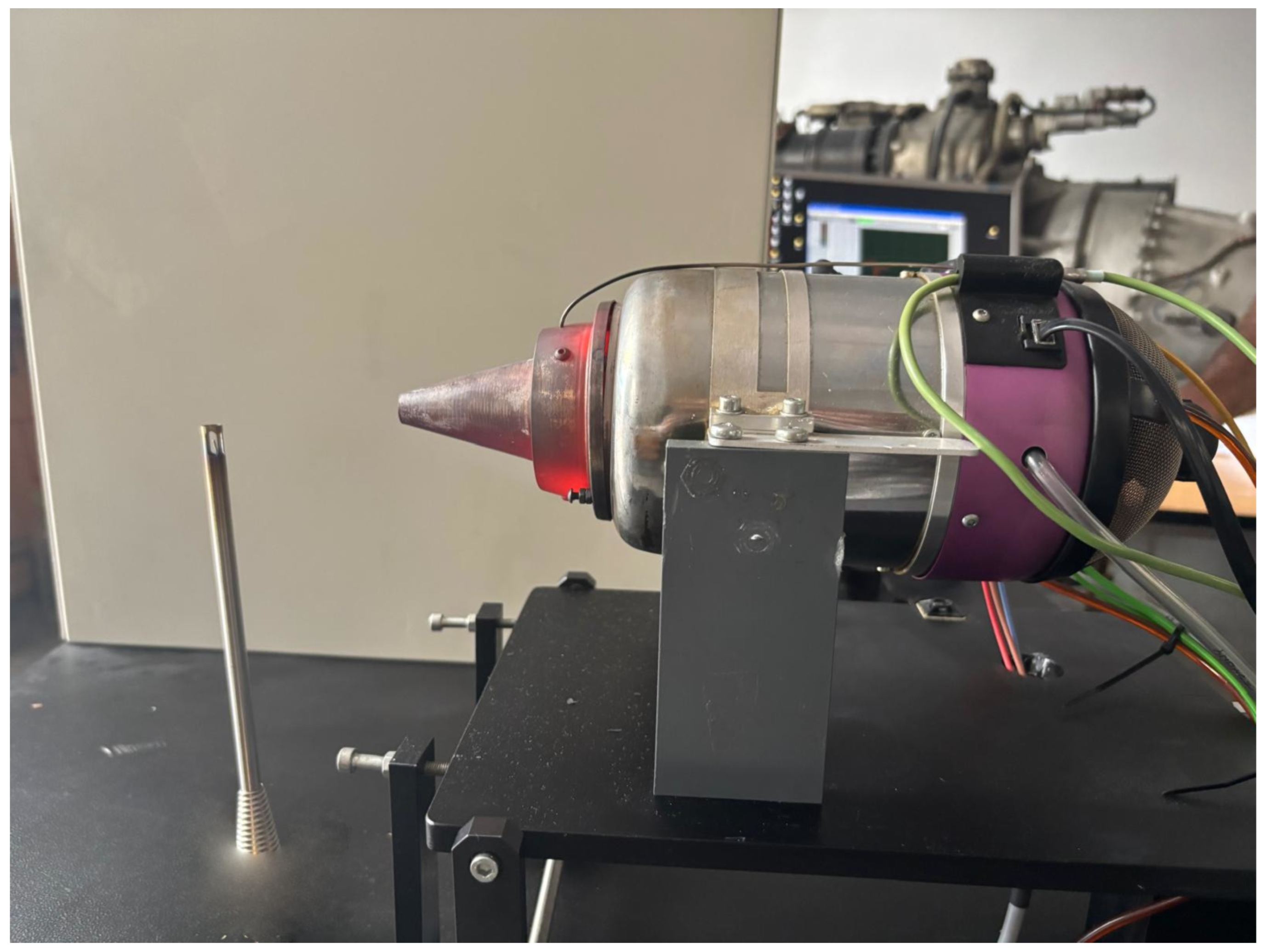
Experimental validation of the proposed modular testing facility was performed using three fuel formulations: an etalon reference blend consisting of kerosene with 5% AeroShell 500, and two alternative fuel mixtures containing polyethylene pyrolysis oil at 10% and 20% volumetric fraction, respectively, also blended with kerosene and 5% AeroShell 500. The experimental runs confirmed that the installation enabled stable start-up, continuous monitoring, and real-time acquisition of thermodynamic and mechanical parameters for all tested fuels. In
Figure 3 the micro gas turbine engine is illustrated during experimental operations. The
Table 4,
Table 5,
Table 6,
Table 7,
Table 8,
Table 9,
Table 10 and
Table 11, represented bellow, resume the experimental results procured during the experiments for each different regime.
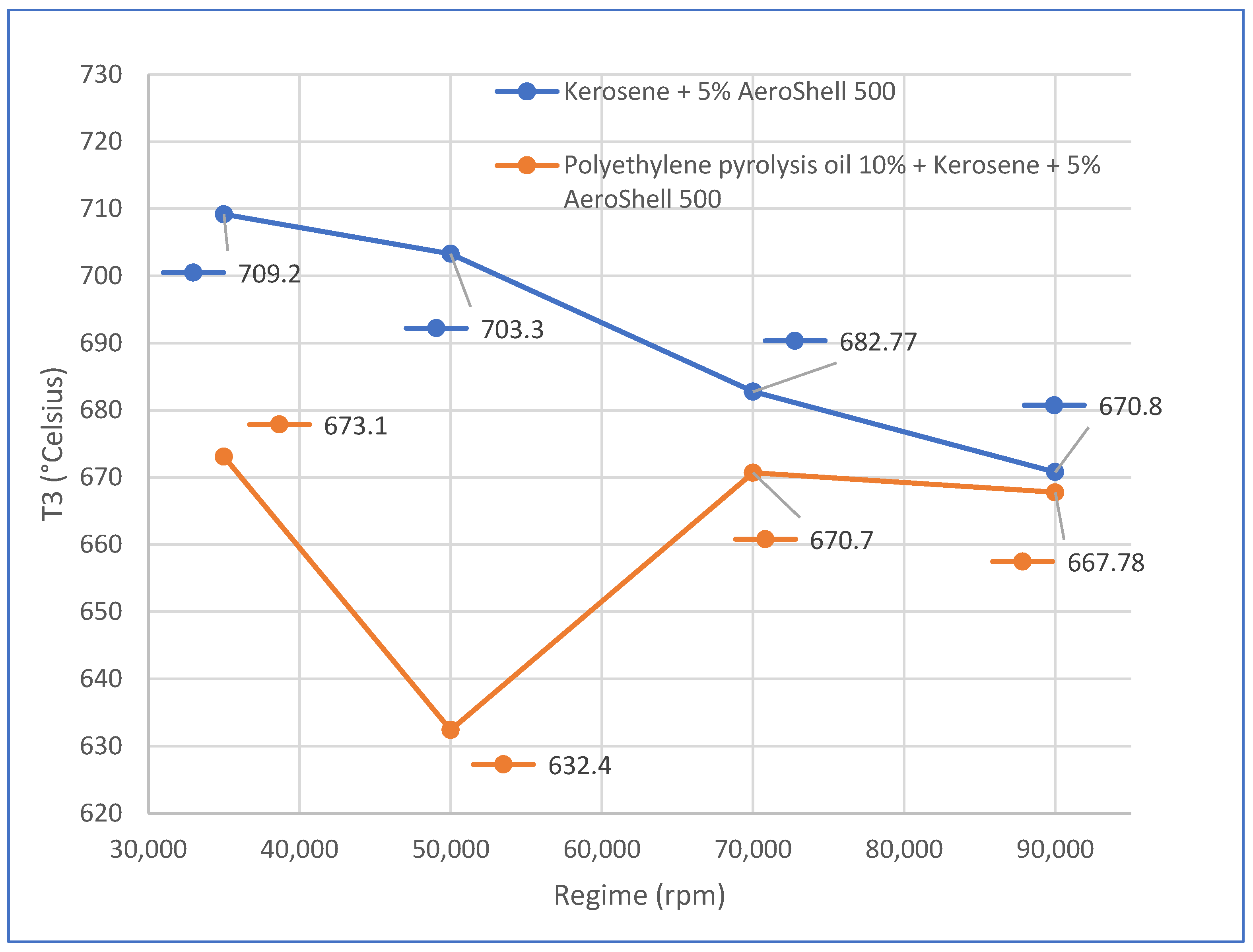
Significant differences were observed in the measured turbine inlet temperature (T3) when operating with pyrolysis-derived fuel blends. In particular, reduced T3 values were accompanied by lower mechanical work output compared with the reference fuel mixture. These results suggest either incomplete combustion of the alternative fuel blends or a lower effective heating value relative to standard kerosene–oil mixtures.
Additionally, the fuel mass flow rate was consistently higher for the blends containing polyethylene pyrolysis oil, while the air mass flow rate remained similar or slightly reduced. This imbalance between fuel and air supply indicates a less stable operating regime of the microturbine under alternative-fuel conditions. Ideally, air flow should increase proportionally with fuel flow; therefore, the observed discrepancy may be associated with partial clogging of the fuel filter or with increased viscosity of the blends caused by suspended particulate residues.
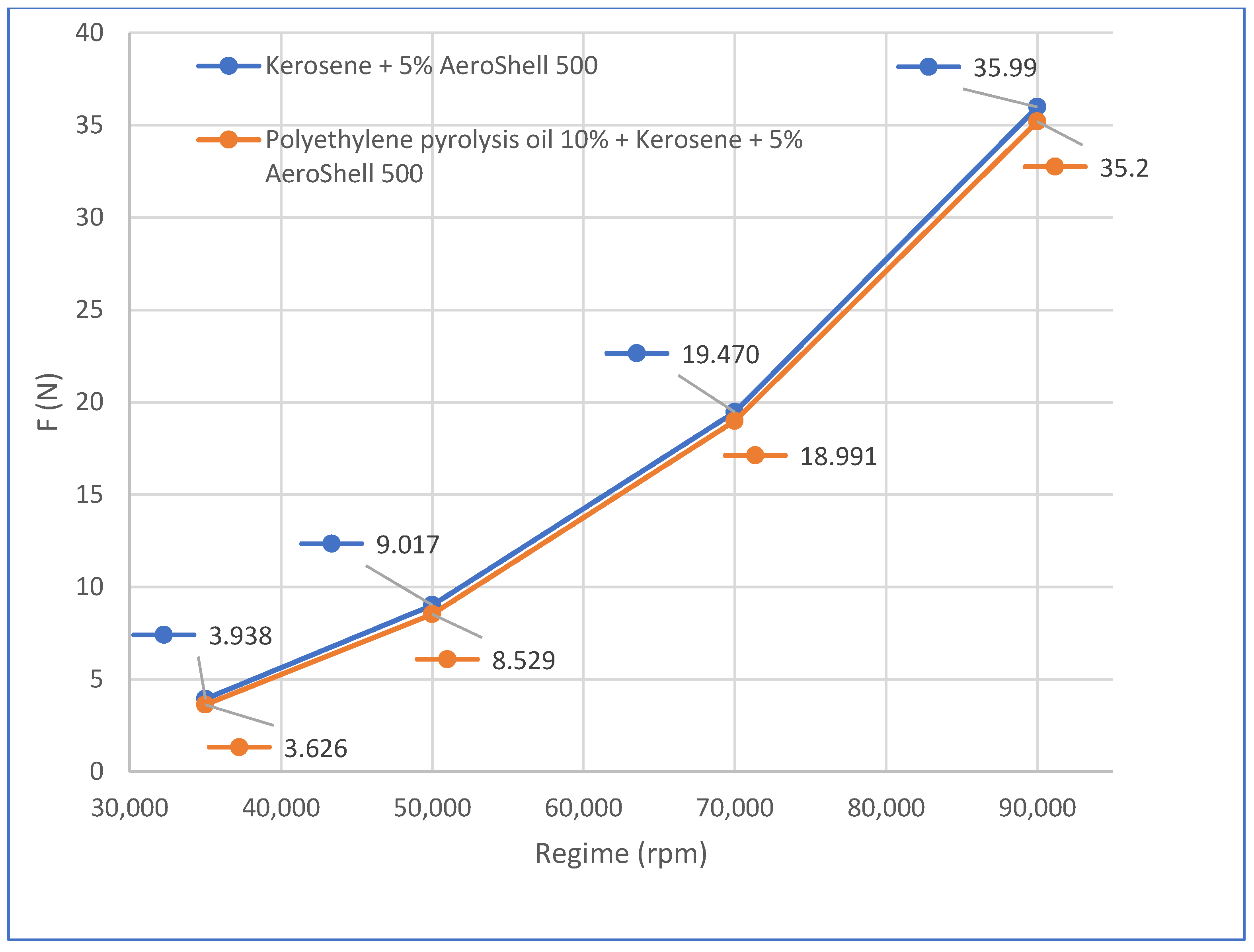
The measured thrust force was also lower for the pyrolysis-containing mixtures, confirming a reduction in propulsion efficiency when compared with the etalon fuel. Although no elemental CHNS analysis was performed, variations in elemental composition cannot be excluded and may significantly influence pollutant emission levels. Regarding sulfur dioxide (SO2) emissions, a decreasing trend was observed at high rotational speeds for pyrolysis-based mixtures, which may be explained by the absence of sulfur in the original polyethylene feedstock.
Overall, these experimental results demonstrate the capability of the modular testing installation to operate with both conventional and alternative fuel blends, while providing detailed diagnostic insight into combustion performance and emission behavior.
4. Discussion
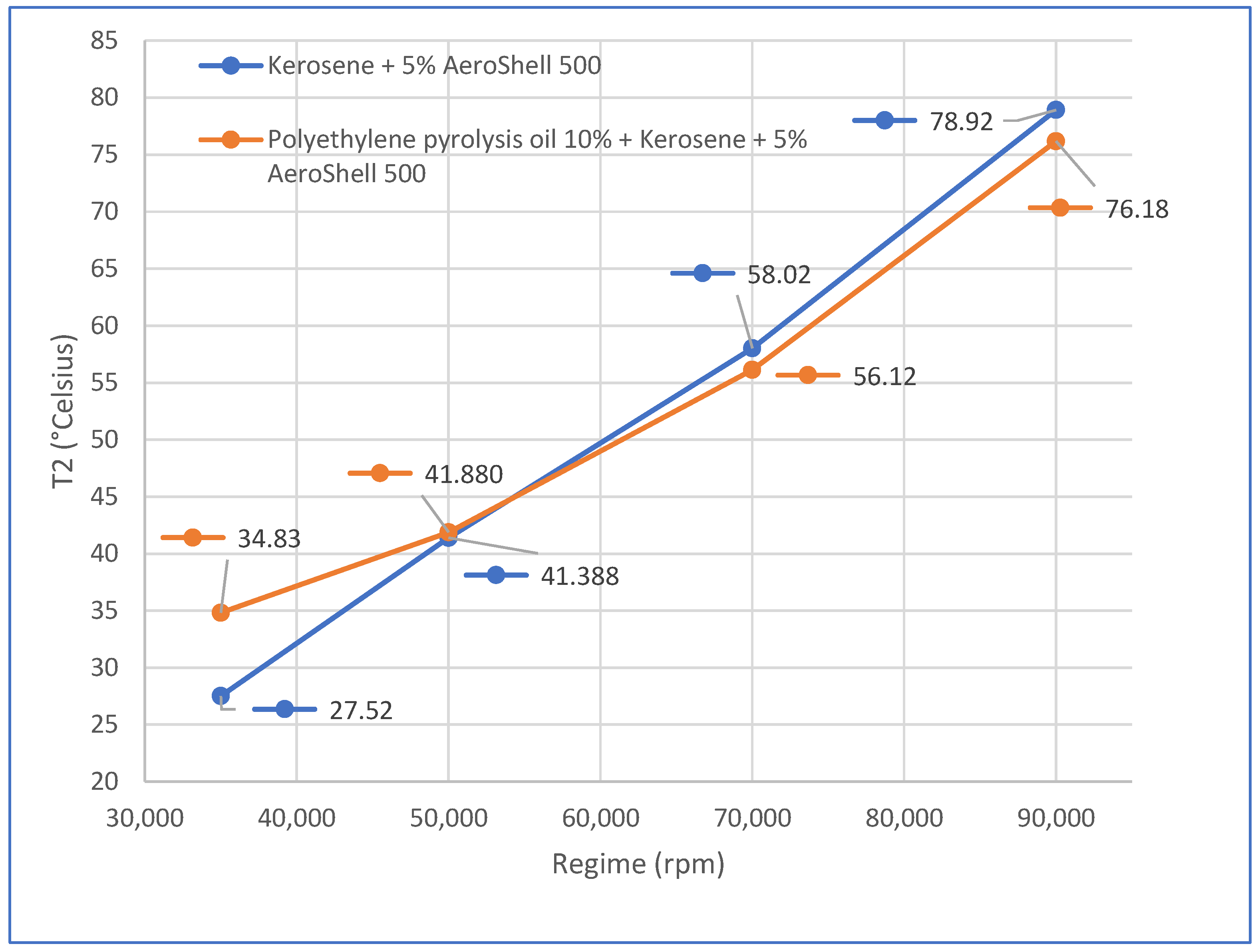
The experimental campaign was primarily intended to validate the functionality, reliability, and versatility of the proposed modular testing facility rather than to optimize the performance of pyrolysis-derived fuels. The results confirm that the installation provides an effective laboratory-scale platform for systematic evaluation of alternative aerospace fuel mixtures under controlled and repeatable conditions.
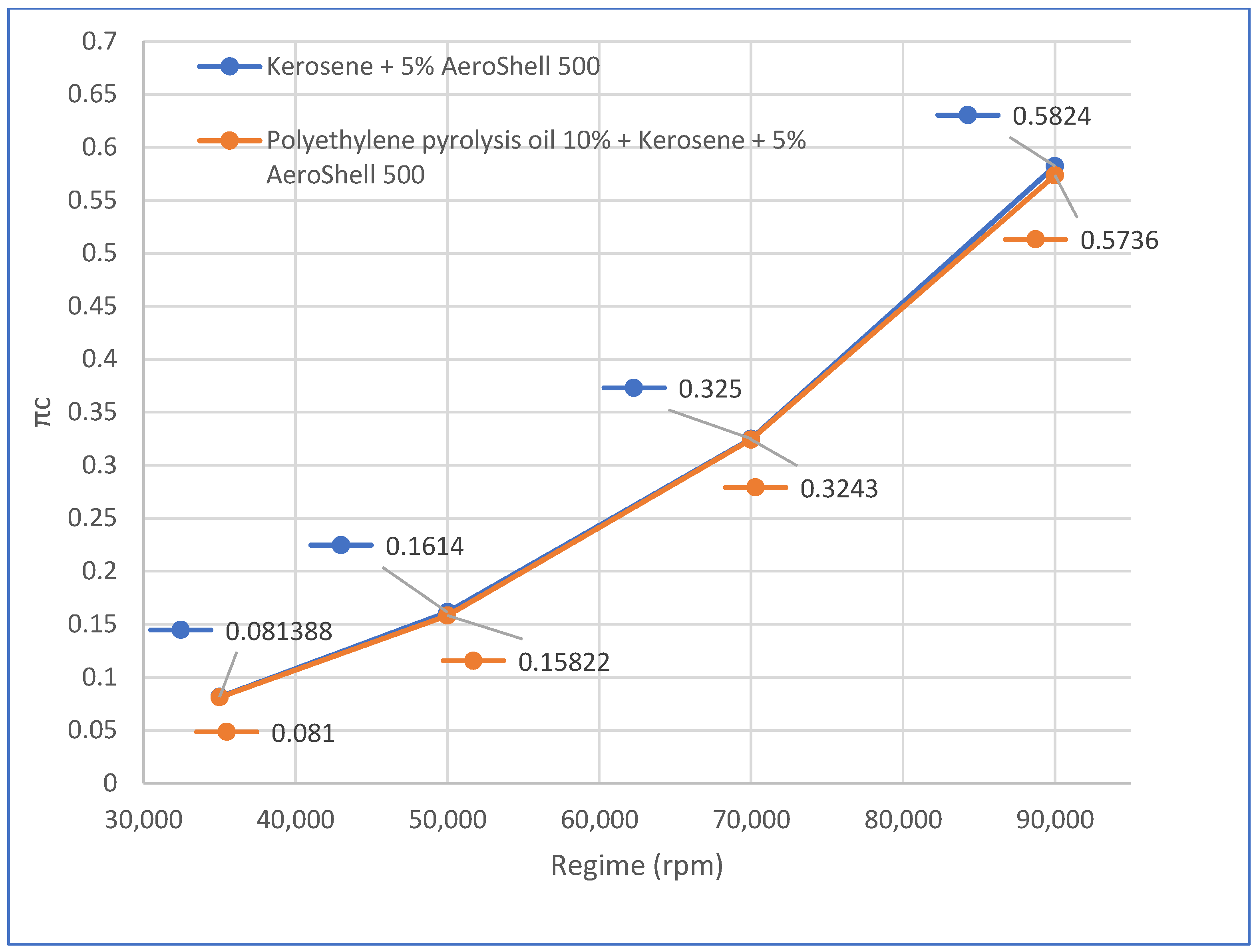
Figure 4,
Figure 5,
Figure 6 and
Figure 7, presented below, illustrate the variations of different important parameters to be inspected for these specific experiments in relation with the engine speed for kerosene and polyethylene pyrolysis oil blends.
The observed reductions in T3 temperature, thrust, and combustion stability when using polyethylene pyrolysis oil blends highlight the importance of dedicated testing infrastructures capable of identifying fuel-related limitations, such as incomplete combustion, viscosity effects, or particulate contamination. These findings demonstrate the facility’s capability to detect operational deviations through correlated measurement of fuel flow, air flow, thermodynamic parameters, and exhaust gas composition.
The variation in turbine outlet temperature T3 across the tested rotational regimes reveals two physically significant trends that further demonstrate the diagnostic capability of the installation. The monotonic decrease in T3 with increasing rotational speed observed for all fuel formulations is consistent with the progressive dilution of combustion exhaust gases by the growing air mass flow rate, a characteristic behavior of this class of micro gas turbine. More significantly, the gap between the T3 values of the reference fuel and the 10% polyethylene pyrolysis oil blend peaks at the 50,000 rpm regime and narrows substantially at higher speeds. This behavior reflects the sensitivity of the undistilled pyrolysis fraction to increased fuel flow demand at intermediate regimes, where viscosity and particulate content most acutely affect atomization quality and combustion completeness. At higher rotational regimes, elevated combustion chamber conditions promote more complete combustion of the blend, converging T3 values toward those of the reference, but at a consistently higher fuel consumption rate, as evidenced by the Qc data, confirming reduced combustion efficiency rather than equivalent thermodynamic performance. The facility’s ability to capture and resolve these regime-dependent phenomena through correlated T3, Qc, and emission measurements validates its suitability as a sensitive diagnostic platform for alternative fuel evaluation.
A key advantage of the proposed modular architecture is its applicability to a broad range of sustainable fuel candidates beyond the specific mixtures tested in this study. The facility can be adapted for comparative investigations of biofuels, synthetic aviation fuels, waste-derived fuels, and blended formulations, enabling accelerated qualification processes for future aerospace propulsion applications.
Furthermore, the integration of plastic waste pyrolysis fuels into aerospace research supports a broader industrial sustainability perspective. Pyrolysis oils can potentially be produced not only from municipal plastic waste but also from polymer-based waste streams generated within the aerospace industry itself, such as composite resins, packaging materials, and polymeric consumables. In this context, the proposed testing installation contributes to the development of a closed-loop industrial ecosystem, where aerospace waste is converted into alternative fuel resources and experimentally assessed within the same sector. This approach aligns with long-term decarbonization strategies and circular-economy objectives in aviation.
Future work should include detailed chemical characterization of pyrolysis-derived blends, including CHNS elemental analysis and heating value determination, as well as expanded emission measurements to further quantify environmental performance.
5. Conclusions
The present study detailed the design, integration, and experimental validation of a modular laboratory-scale gas turbine testing facility dedicated to the evaluation of sustainable fuels obtained from plastic waste pyrolysis for aerospace propulsion applications. The installation was conceived as a functionally representative micro gas turbine system, integrating a radial compressor, annular combustion chamber, and axial turbine mounted on a common shaft, complemented by a dual-branch fuel handling architecture, automated ignition system, real-time exhaust diagnostics, and synchronized data acquisition capabilities.
From a technical standpoint, the facility demonstrated full operational autonomy and controlled start-up under all tested conditions. The integrated fuel conditioning subsystem, including thermal stabilization via a Stirling-assisted tank and electronically controlled pumping, ensured reproducible fuel delivery and enabled comparative assessment between reference kerosene-based fuel and polyethylene pyrolysis oil blends.
The command and data acquisition system allowed continuous monitoring of turbine inlet temperature (T3), compressor outlet temperature (T2), rotational speed, compressor pressure ratio (πc), fuel consumption (Qc), airflow rate (Qa), and thrust (F), while correlated exhaust gas analysis (O
2, CO
2, CO, NO, NO
2, NOx, SO
2) and high-speed flame visualization supported detailed combustion diagnostics.
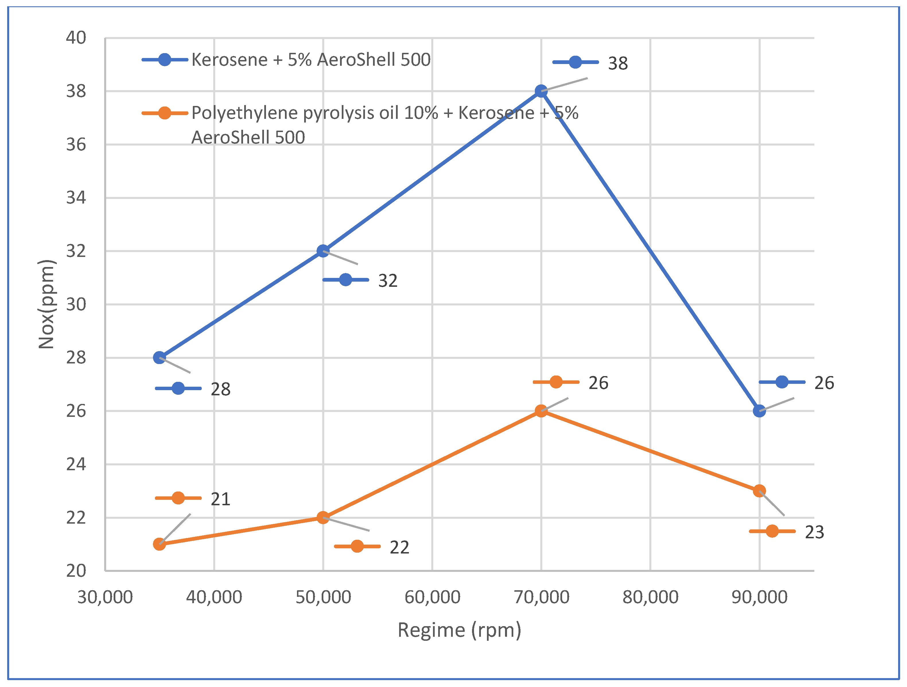
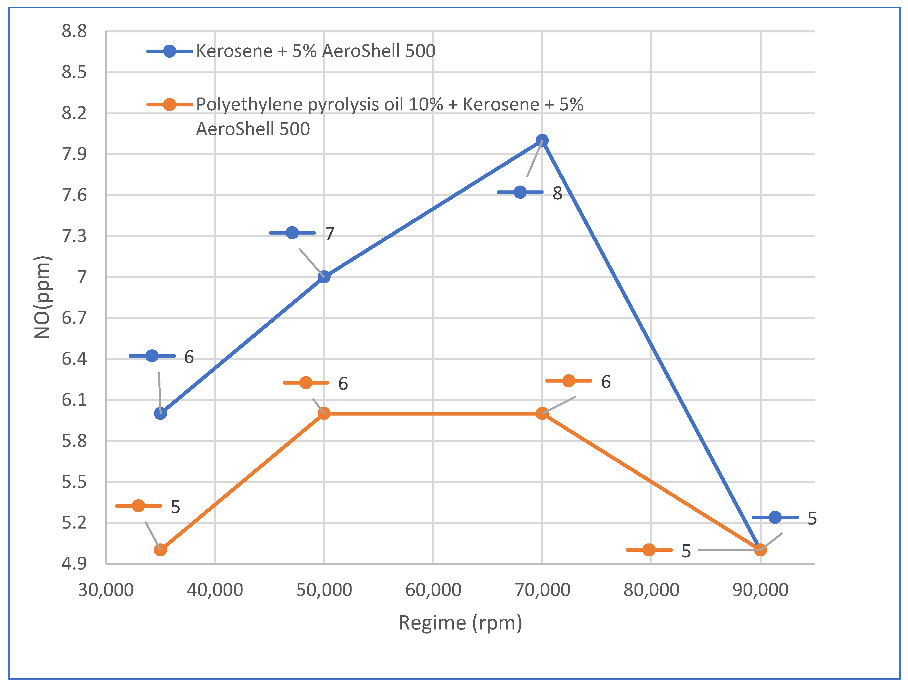
Figure 8,
Figure 9,
Figure 10,
Figure 11 and
Figure 12, presented below, illustrate the variations of different important exhaust gas emissions to be inspected for these specific experiments in relation with the engine speed for kerosene and polyethylene pyrolysis oil blends.
Experimental results obtained across rotational regimes from 35,000 rpm to 90,000 rpm confirm the robustness and sensitivity of the testing platform. When operating with the 10% polyethylene pyrolysis oil blend, the system maintained stable combustion at all regimes, although measurable performance deviations were observed. Specifically:
A consistent reduction in turbine inlet temperature (T3) was recorded relative to the reference fuel, indicating lower effective heating value and/or modified combustion kinetics.
Fuel consumption (Qc) increased at higher rotational speeds, particularly at 90,000 rpm, while airflow rate (Qa) remained approximately constant, suggesting altered air–fuel ratio conditions.
Thrust values were systematically lower for the pyrolysis blend, confirming reduced propulsion efficiency under identical compressor pressure ratios.
Emission measurements showed a clear reduction in SO2 and NOx levels compared to the reference fuel, particularly at medium and high rotational speeds, consistent with the sulfur-free nature of polyethylene feedstock.
The 20% polyethylene pyrolysis oil blend revealed the diagnostic strength of the facility. While operation at 35,000 rpm was achievable, it was characterized by increased fuel flow, reduced rotational stability, decreased compressor pressure ratio, and lower thrust. At rotational regimes ≥50,000 rpm, the engine exhibited operational instabilities due to the unrefined nature of the fuel mixture, and no reliable data could be acquired. This outcome demonstrates the facility’s capability to detect instability thresholds, fuel-related flow perturbations, and combustion irregularities under controlled conditions.
A major technical contribution of the proposed installation lies in its integrated, multi-parameter diagnostic architecture. The ability to correlate thermodynamic performance, mechanical output, fuel–air interaction, and emission formation within a single modular platform enables comprehensive fuel characterization beyond simple thrust measurements. The high-speed optical monitoring system further enhances diagnostic resolution by permitting visualization of flame stability and transient combustion phenomena, supporting interpretation of the measured T3 reductions and flow imbalances.
The results confirm that the modular testing facility is not merely a demonstrative microturbine setup but a structured experimental infrastructure capable of:
Quantifying performance degradation associated with alternative-fuel viscosity and particulate residues;
Detecting air–fuel imbalance effects through correlated Qc–Qa analysis;
Evaluating combustion efficiency through combined T3, thrust, and emission measurements;
Identifying instability regimes and safe operational envelopes for novel fuel blends.
Overall, the study validates the proposed modular installation as a technically robust, flexible, and scalable experimental research platform. The architecture supports systematic parametric studies, fuel qualification screening, and controlled comparative analyses of sustainable aviation fuels. Its modular design, autonomous operation, integrated diagnostics, and capability to operate up to 90,000 rpm position it as a valuable laboratory-scale infrastructure for advancing waste-to-fuel technologies and supporting the transition toward circular and low-carbon aerospace propulsion systems.
Future work should include detailed physicochemical characterization of the pyrolysis-derived fuel fractions, encompassing CHNS elemental analysis, calorific value determination, viscosity measurements, and GC-MS compositional characterization to establish a comprehensive fuel property database supporting rigorous combustion interpretation. Refinement of the pyrolysis fuel fractions through atmospheric distillation is planned to eliminate residual solid suspension and enable stable operation at blend ratios exceeding 20% v/v across all rotational regimes. Expanded transient regime investigations will further exploit the diagnostic capabilities of the testing installation, including detailed high-speed optical flame visualization campaigns for more compositionally divergent fuel formulations, where visual diagnostics will provide greater discriminatory value than was achievable in the present validation study. A rigorous uncertainty analysis with full propagation of measurement errors across all acquired parameters and graphical representation of error ranges will be conducted once replicate testing data are available. Triplicate experimental runs under identical fuel formulations and process conditions are planned as a priority item, providing the statistical basis required for reproducibility assessment and meaningful uncertainty quantification. Testing of higher pyrolysis oil substitution ratios, additive-free fuel fractions, and fuels derived from alternative feedstocks (including polypropylene, mixed plastic waste streams, and polymer-based aerospace industry waste) will broaden the comparative evaluation scope of the installation. Finally, the regime-dependent combustion efficiency phenomena identified in the present study, particularly the T3 convergence behavior at higher rotational speeds and its relationship to fuel atomization quality and combustion chamber conditions, will be systematically investigated through correlated fuel flow, thermal, and emission measurements across an extended operating envelope.
6. Patents
A national patent request was filed prior to the present work in relation to the new testing installation concept: Modular testing installation for sustainable fuels obtained from plastic waste pyrolysis products for aerospace engines, Alexa-Andreea Crisan, Radu Eugen Kuncser, Madalina Botu, reference no. A/00059-OSIM: 10.02.2026.