Article

Wire-Based Solid-State Propellant Management System for Small Form-Factor Space Propulsion

Department of Plasma Power Plants, Bauman Moscow State Technical University, 2-ya Baumanskaya Street, 5/1, 105005 Moscow, Russia
*
Author to whom correspondence should be addressed.
Inventions 2025, 10(5), 75; https://doi.org/10.3390/inventions10050075
Submission received: 16 July 2025 / Revised: 20 August 2025 / Accepted: 22 August 2025 / Published: 26 August 2025

Abstract

The development of dynamic missions of small satellites requires the development of efficient, compact, and reliable propulsion systems (PSs). This paper investigates a propellant storage and supply system (PSSS), utilizing alternative solid-state propellants in the form of wire. To establish the background to the suggested solutions implemented in the proposed system, two types of comparative analysis were performed. The first one compared different types of propellant management system designs while the second juxtaposes a variety of propellants. It is shown that the solid-state systems for small satellite operations are advantageous, while the selection of propellants should be focused on safe operations and operational requirements. The principle of operation and structural design of the proposed wire-based solid-state propellant management system are discussed, including the assessment of its engineering realization. The strategies to mitigate the potential problems with the system’s operations such as propellant unwanted deposition and corrosive effects are suggested. An example of using the proposed system is provided, which considers a deep space dynamic mission case. The proposed PSSS architecture is dedicated to increasing the energy efficiency, resilience to environmental factors, and suitability for small satellite platforms, including that of the CubeSat format.

1. Introduction

Over the last two decades, advancements in space technologies have revolutionized the landscape of small satellite systems, creating an urgent need in propulsion systems tailored specifically for small-scale platforms [1]. The demand for these systems is especially focused on those capable of delivering the high total impulse per unit of mass and volume, particularly for dynamic missions [2]. Given the constrained nature of small satellites, maximizing the efficiency of every component becomes imperative to achieve high maneuverability and long-term non-serviceable operations [3]. Central to this challenge is the selection of propellants that dictate the performance envelope of any propulsion system [4].
Traditional propellants, while adequate for routine space missions, fall short when faced with the rigors of dynamic operations. Small satellites undertaking exploratory, scientific, or commercial endeavors often operate in environments demanding flexible and adaptive propulsion solutions [5]. In such settings, propellants must balance high storage density, long-term stability, and ease of activation with minimal energy inputs [6].
Emerging trends suggest that integrated propulsion architectures, blending plasma thrusters with dedicated propellant storage and supply systems (PSSSs), hold immense potential. These hybrid arrangements allow for the seamless integration of alternative solid-state propellants, unlocking new frontiers in small satellite maneuverability and long-term operations [7,8]. Hall-effect (HET) and ion (IT) thrusters have historically dominated the scene due to their remarkable efficiency in accelerating single-component ions [9]. Nevertheless, as missions grow more ambitious, conventional technologies encounter limitations [10]. Dynamic space missions frequently call for denser propellants, stretching the boundaries of what these legacy systems can reliably accommodate [4]. Electrodeless plasma thrusters (EPTs) could potentially reshape the development trajectory of small satellite propulsion for deep space dynamic missions [11,12,13,14,15]. Unlike their predecessors, EPTs sidestep direct plasma–electrode interactions, relying instead on electrodeless plasma generation and acceleration mechanisms [16,17,18]. This paradigm shift brings numerous advantages such as the capability of handling multi-component plasmas and accommodating chemically reactive substances, the flexible tuning of thrust and specific impulses across broad operational modes, the absence of electrodes minimizing component erosion, extending lifespan, and lowering maintenance overheads [19,20,21].
This work presents a detailed investigation of a novel propellant storage and supply system implementing wire-shaped solid-state materials. Designed explicitly for small satellite applications, this system seeks to amplify performance, fortify safety, and bolster adaptability for dynamic space missions, overcoming such problems for small satellite propulsion due to the strict limits on the propellant stored onboard and the engineering obstacles related to the utilization of the conventional fluidic and solid-state propellants.
In the following, in Section 2, a comparative analysis of the propellant management systems based on gaseous and solid-state propellants and a comparative analysis of the use of gaseous and solid-state propellants are discussed to determine the most limiting factors in the development and operation of the small propulsion systems. In Section 3, the design and principles of the operations of the proposed propellant storage and supply system are presented. Section 4 presents the discussions on the advantages of the proposed propellant management system in comparison to the systems of the modern state-of-the-art and the prospective multimode propulsion system that can use this propellant management system. Section 5 presents the conclusion.

2. Materials and Methods

In order to propose an effective solution for tackling one of the most limiting factors for the development and operation of the small form-factor propulsion system for dynamic space missions, that is the propellant management, two types of comparative analyses are performed. In the first one, fluid- and solid-state propellant management systems are juxtaposed. In the second analysis, the physical properties of different propellants are considered in the context of their utilization for propulsion-intensive missions. For the investigation in Section 2, a theoretical discussion is performed.

2.1. Comparative Analysis of Propellant Management Systems

In conventional propellant storage and supply systems for electric propulsion systems including, for example, Hall-effect, ion, and electrodeless plasma thrusters, noble gases such as krypton, xenon, or argon are typically used as propellants. These systems include a tank where the propellant is stored in either liquid or gaseous form, a throttle system to reduce the pressure at the inlet of the electromagnetic or mechanical valves, and filters that are necessary to ensure gas purity injected into the gas discharge chamber and the cathode neutralizer [22]. The main drawback of such systems is the limited storage density of the propellant and the requirement for high-pressure sustained in the propellant storage tanks, with pressures reaching up to several dozen MPa, as well as high-pressure valves, which are characterized by significant mass and power consumption. Such PSSSs are used, for example, in a flight-tested bi-directional electrodeless plasma thruster [4].
PSSSs based on alternative solid-state propellants include a system of thermal throttles and heaters, which are necessary for the vaporization and throttling of the vapors, as well as for preventing condensation of the propellant on the system components [23]. The propellant is stored in a tank made of chemically and thermally resistant material [24]. Temperature control can be carried out by a set of temperature sensors. The valves enable flow shutoff. Such PSSSs in full or in that are part similar to this description can be found in thrusters like ThrustMe’s NPT-30 and Busek’s BIT-3 ion thrusters [25].
A comparative analysis of the fluid- and solid-state propellant systems for applications onboard small satellites is presented in Table 1.
It can be noted that the use of the propellant storage and supply system for alternative propellants eliminates the need for high-pressure propellant tanks and high-pressure valves and allows for the use of higher-density solid-state propellants that can provide the opportunity to increase the total impulse per unit of mass and volume. These advantages are especially important for small satellites, such as those of CubeSat format, where the mass and volume service system reduction and power requirement minimizations are critical. However, the main drawback of using solid-state propellant systems can be accounted to the potential for the propellant deposition inside PSSS components, which can lead to clogging and the interruption of propellant flow, as well as the propellant deposition on the surfaces of solar panels or service systems of the satellite. Therefore, when selecting a propellant, it is essential to consider the likelihood of propellant deposition on the satellite’s surfaces and ensure the appropriate conditions to prevent it. In addition, a PSSS based on solid-state propellants can also be applied for an advanced dual-mode rocket engine/plasma thruster that uses metal vapors as fuel/propellant and the atmosphere of other celestial bodies as the oxidizer. The implementation of such a system enables a compact propulsion unit due to the high storage density of metals that can assist interplanetary flights as the plasma thruster and the interorbital maneuvers of other planets as the rocket engine. For example, magnesium undergoes oxidation with significant heat and energy release in the Martian atmosphere and can be used as a propellant for the plasma thruster mode with the first ionization potential of 7.7 eV [28].

2.2. Comparative Analysis of Fluid- and Solid-State Propellants

The selection of the propellant is one of the key tasks in the design of a propulsion system. Thrusters with an electrostatic acceleration mechanism most efficiently accelerate heavy ions, and it is critically important that the ions have uniform mass and charge. In particular, failure to meet these conditions in the ion thruster may lead to degradation of the ion-optical system. In Hall-effect thrusters, the acceleration of ions with varying mass results in reduced ionization efficiency and rapid degradation of the acceleration channel. Interestingly, the EPTs that do not have electrode–plasma contact and utilize electromagnetic acceleration mechanisms do not have these problems.
For example, in HET, the ionization efficiency depends on the ionization cross-section, which is specific to a given ion species, as can be perceived from the following equations [29]:
m ˙ a S c h 3 M V a z V i z   σ i V e L c
L c = e · U m e ω e 2 · ν e ν 1
where V a z is the velocity of non-ionized particles; V i z is the ion velocity; σ i V e is the ionization rate coefficient; M is the mass of a propellant atom; m ˙ a is the mass flow rate; S c h is the channel cross-sectional area; L c is the axial extent of the ionization and acceleration layer in HET; m e is the electron mass; e is the elementary charge; U is the voltage drop across the accelerating layer in HET; ω e is the electron cyclotron frequency; ν e is the effective electron frequency; and ν 1 is the effective collision frequency.
From the condition based on Equation (2), it can be perceived that the use of ions of different masses and charge may lead to instabilities, reduced propulsion system efficiency, and rapid degradation of the gas discharge chamber walls or other plasma-contacted parts of the thruster for the electric propulsion systems with the prevailing electrostatic mechanism of ion acceleration. The use of noble gases is one of the most optimal solutions for these thrusters; however, due to the low storage density and the large mass and volume characteristics of valves, there is a growing need for alternative propellants.
One of promising option as a substitution for fluid-state propellants is iodine due to its compatibility with the electrostatic mechanism of charge particle acceleration, the relatively low ionization potential, and predominantly homogeneous plasma components after its ionization. Yet it has high vapor saturation pressure, allowing it to spend relatively low energy for its sublimation. However, iodine is a chemically active halogen and may cause extensive corrosion of thruster and satellite components. This effect is especially pronounced when iodine vapor is present in a humid environment, which destroys protective oxide layers. The use of metals can eliminate corrosion issues; however, due to the low vapor pressure of some metals, condensation may occur on cold surfaces with a high accommodation coefficient.
Certain metals, such as mercury, are extremely toxic and pose serious hazards during ground testing. Mercury can also form amalgams, dissolving other metals such as aluminum and copper that are extensively used in space propulsion systems. The use of cesium is highly dangerous due to its extreme reactivity; in the presence of oxygen or water vapor, it reacts instantly. One potential solution to this problem is the development of intermetallic materials in which cesium is embedded within a protective metal matrix and evaporated during thruster operation. This matrix, for example, can be made of gold. Such a capsule must be enclosed in a protective shell containing a passivating material, allowing cesium vapor to immediately react with it and form a safe compound.
The safest metals for using the propellant include zinc, magnesium, and bismuth. However, the use of bismuth requires maintaining a high operating temperature. Unfortunately, bismuth is a relatively expensive metal and its vapor is more toxic compared to that of zinc and magnesium. According to the study [30], zinc is identified as the most optimal propellant for Hall-effect thrusters, providing the highest specific impulse. Zinc vapor is relatively safe for ground testing, requires comparatively low temperatures to generate, has a high atomic mass, and can be effectively used in thrusters with electromagnetic or electrostatic acceleration mechanisms. However, its use is associated with the potential deposition of thin films on thruster and satellite components.
A comparative analysis of the saturated vapor pressures of various propellants is presented in Figure 1. The data for Figure 1 was obtained from reference [28].
The main parameters of the propellants for use in propulsion systems are presented in Table 2. The data for Table 2 were obtained from the following sources [31,32,33].
To mitigate the deposition of exhausted metal particles on the surfaces of the satellite, a secondary thruster could be employed, using a propellant that chemically reacts with the substance to be deactivated to form a safe and stable compound. Alternatively, the critical satellite components susceptible to reaction with the propellant substances can be coated with protective layers. Another approach is to heat these sensitive surfaces to prevent condensation and film formation.

3. Results

The objectives of the proposed wire-based solid-state propellant management system are a reduction in the volume occupied by the propulsion management system, an increase in the accuracy of regulating the flow rate of the propellant, an increase in the rate of change in the flow rate of the propellant in the solid-state-based PSSS, the capability of being used for multimode propulsion systems operating as the chemical rocket engine and the electric propulsion, and the overall enhancement of small satellites’ maneuverability. In the proposed propellant management system, special attention is given to energy efficiency, thermal stabilization, precise temperature control, and mass flow regulation. The magnetohydrodynamic (MHD) pump, thermal throttles, the spool with the spring mechanism, or the servo drive can be used to ensure the required feed accuracy with minimal thermal losses.
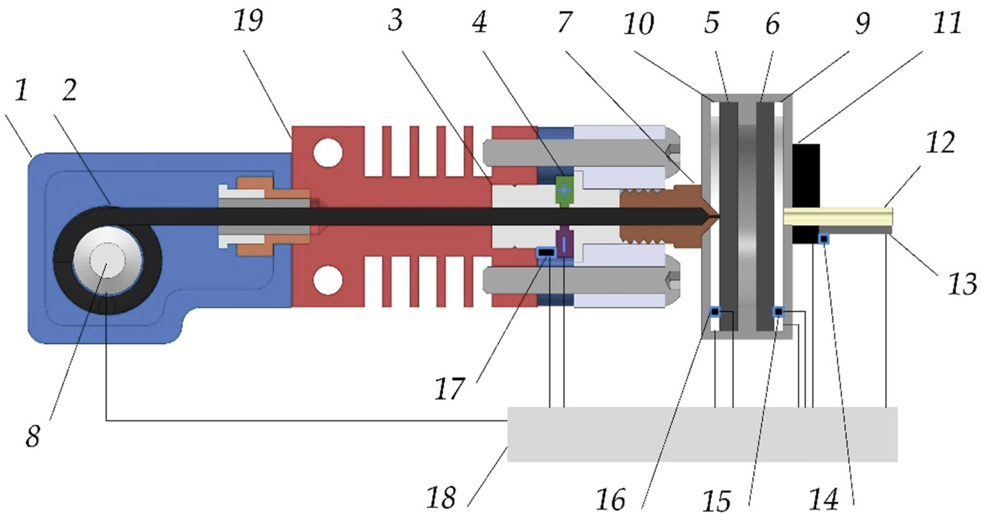
The proposed propellant management system scheme is presented in Figure 2.
The proposed system includes a sealed propellant storage tank (1) used to store the propellant (2) in solid rod form. Melting of the propellant is achieved by heat input from a tank heater (3). An MHD pump (4) transfers the molten propellant to the sublimation zone, where first and second thermal throttles in the form of porous filters (5,6) are installed. These filters may consist of a perforated plate, microchannel structures, or a set of plates arranged at specific intervals along the main axis of the tank in order to reduce the propellant flow pressure and ensure uniform distribution. The propellant storage tank (1) is hermetically connected to a nozzle fitting (7) of a specified diameter by means of a threaded joint, soldered joint, welded joint, adhesive joint, or various combinations thereof. This is performed to ensure necessary sealing and corrosion resistance under conditions of high and low temperatures, abrupt temperature fluctuations, high chemical reactivity of the propellant (2) in contact with the tank components, mechanical stresses, low- and high-frequency vibrations, and shock loads.
The precision of propellant (2) delivery is ensured by the primary feed system, which is equipped with a spring mechanism or a servo drive (8), an MHD pump (4), and first and second thermal throttles in the form of porous filters (5,6) that are in thermal contact with positive temperature coefficient (PTC) heaters (9,10). By varying the temperature of the propellant vapor, its viscosity and hydrodynamic resistance can be adjusted, enabling control over the vapor flow rate.
An electromagnetic valve (11) regulates the specified propellant (2) flow rate. The third thermal throttle (12) equipped with a heater (13) provides further delivery of propellant vapor into the GDC (gas discharge chamber) thruster, preventing condensation.
Temperature control is performed by a set of thermal sensors (14,15,16,17). The control unit (18) receives data from each of the temperature sensors (14,15,16,17) and manages the temperature of the thermal throttles (5,6,12), the MHD pump (4), and the primary feed system (8). A heat exchanger (19) is used to dissipate excess heat and prevent melting of the propellant (2) in the storage area (see Figure 2).
The proposed technology is intended to be used as part of the multimode propulsion system of the satellite of a small form-factor performing dynamic missions including interplanetary flights and interorbital maneuvers. The proposed propellant management system can utilize a wide range of metals to be used for the multimode propulsion system, which can be oxidized by CO2, SO2, F2, Cl2, NO2, and vapors of various acids.
The parts of the system, which are in contact with the propellant, must be made of chemically resistant materials. These parts have to withstand the effects of chemically active substances which can be in solid, liquid, or gaseous states in a temperature range of −60 to 1000 °C. These materials must also be resistant to vibrations and shocks that may occur when the satellite is launched into a given orbit using a launch vehicle. The materials that are least susceptible to corrosion and provide the required mechanical characteristics are, for example, pure molybdenum, pure tantalum, pure nickel, pure platinum, aluminum oxide (Al2O3), zirconium dioxide (ZrO2), silicon nitride (Si3N4), silicon carbide (SiC), aluminum nitride (AlN), titanium diboride (TiB2), and boron carbide (B4C). The use of pure aluminum, copper, tin, and iron can be unacceptable. The presence of water vapor can significantly increase the rate of corrosion of certain materials, as water contributes to the decomposition of the protective oxide film, so it is very important to remove water vapor from the tank for storing the solid-state propellant.
The proposed system can be realized in using a compact volume. Based on the preliminary engineering assessments, the length of the system can be 190 mm, with a maximum width and height of 56 mm. The wet mass of the system can be up to 1 kg depending on the length of the wire, the mass of the cooling system, and the mass of the MHD pump.
The flow rate of the propellant is determined by the combined influence of two factors: the rate of its condensation in a porous medium and the viscosity of the vapor phase. A decrease in the surface temperature of the porous element contributes to an increase in the intensity of the vapor condensation of the propellant, which leads to partial or complete clogging of the filter channels and, as a result, a decrease in total flow. At the same time, the vapor filtration process is influenced by its viscosity—as the temperature increases, the viscosity increases, which leads to an increase in the hydraulic resistance of the porous medium and, consequently, a decrease in the flow rate of the propellant. In such systems, the flow rate of the propellant can be determined by Darcy’s law [34]:
q = k S c h μ · p L = k S c h μ · ( p 1 p v a p o r ) L ,
where q is the volumetric flow rate; k is the coefficient of the medium permeability; μ is the dynamic viscosity; p is the pressure drop; L is the given distance over which the pressure drop is considered; p 1 is the pressure in the first thermal throttle; and p v a p o r is the saturated pressure of zinc.
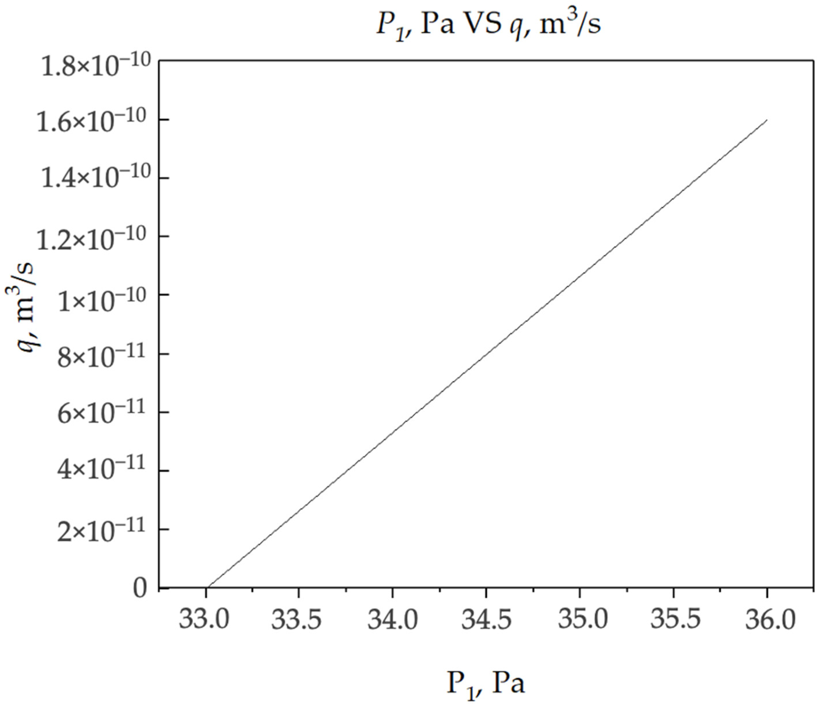
Considering the zinc storage and supply system based on the proposed technology, assuming the thickness of the first thermal throttle is 4 mm, the operational temperature is 700 K, and the nozzle cross-section is 0.5 mm2, using Equation (3), it is possible to obtain the dependance of the volumetric flow rate of liquid zinc, q , from the pressure in the first thermal throttle, p 1 . Meanwhile the second pressure required to calculate the pressure drop in Equation (3) is the saturated pressure of zinc, p v a p o r , at a temperature of 700 K. This dependence is shown in Figure 3.
For the gaseous propellants, if the filter surface temperature is higher than the condensation temperature of the propellant, a decrease in the flow rate will be achieved by increasing the vapor temperature of the working fluid—the viscosity will increase and the filtration rate will decrease.
If the surface temperature of the porous body is lower than the vapor condensation temperature of the propellant, condensation and flow locking will occur. The higher the vapor deposition rate of the propellant, the lower the surface temperature of the porous body.
The flow of particles sublimating from the surface of a solid-state body, Γ o u t , can be determined using the Hertz–Knudsen dependence [35]:
Γ o u t = α ( p v a p o r T p ) 2 π M k B T ,
where p v a p o r T is the saturated vapor pressure of the propellant; p is the pressure of the surroundings; α is the coefficient of adhesion of gas molecules to the surface; k B is the Boltzmann’s constant; and T is the vapor temperature of the propellant in the sublimation zone.
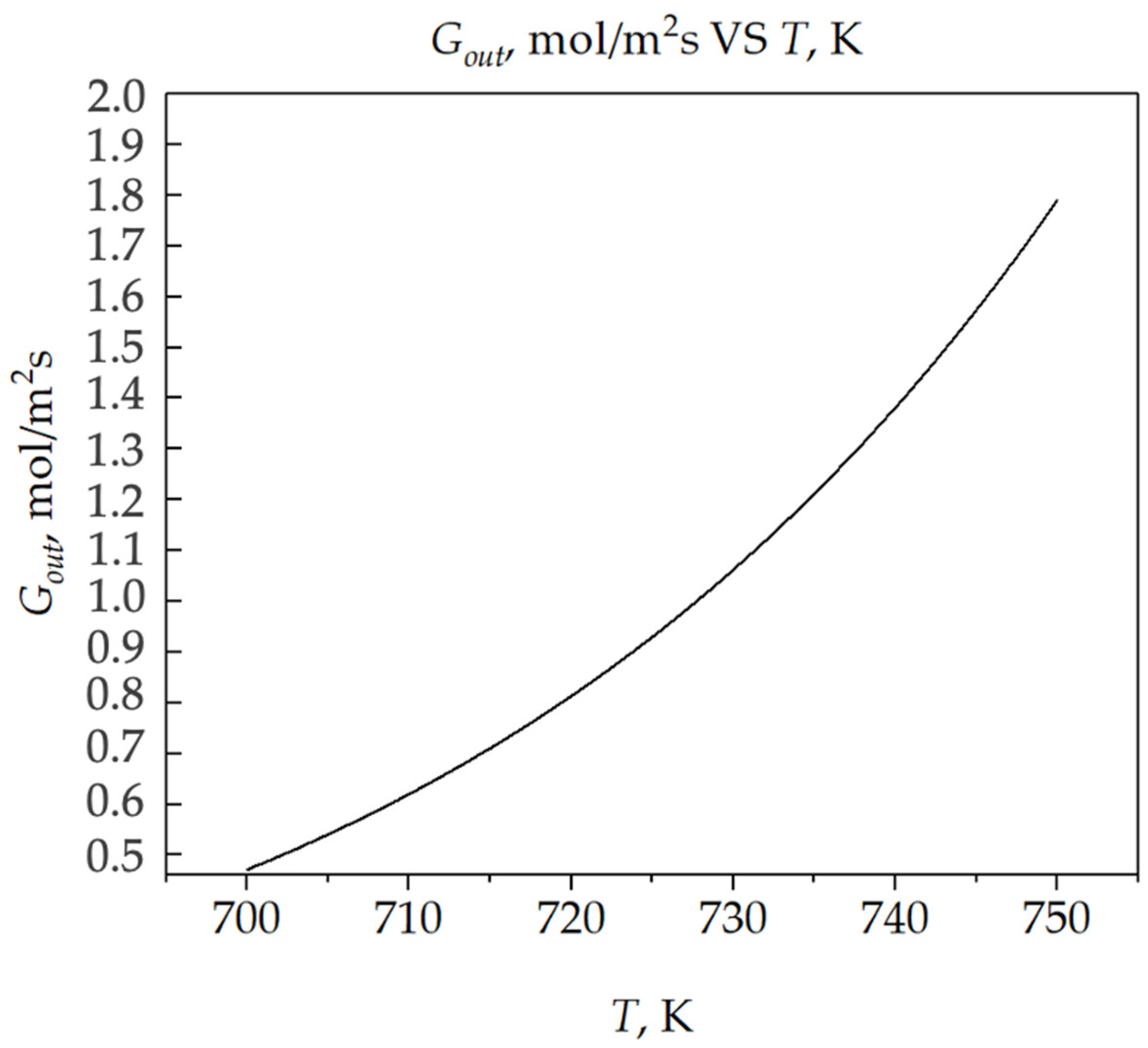
For the same system parameters discussed above, and assuming that the pressure of the surroundings is zero, it is possible to obtain the dependance of the zinc evaporation rate per unit of volume versus the temperature in the sublimation zone (see Figure 4).
It is hypothesized that a wire-form solid propellant feed, driven by an MHD mechanism and heated porous throttles, can outperform conventional solid-state PSSSs in terms of mass, volume, and dynamic flow control.
In a conventional solid-state PSSS, the propellant is sublimated from the surface that is in contact with the thermal throttle. The conventional systems have some operational drawbacks related to their design. First, the sublimating surface is maintained in contact with the thermal throttle by mechanically moving mechanisms that can generate unwanted moments onboard a satellite. Also, the processes of sublimation from the surface of relatively vast areas can be non-uniform, which can result in difficulty controlling the propellant flow rate.
In the proposed propellant management system, it is proposed to feed the propellant in the sublimation zone by means of an MHD pump. This technology can reduce the mechanical moments created by the moving solid parts onboard a satellite and increase the reliability of the system, preventing the solid body from getting stuck when it is fed to the sublimation zone. The use of the relatively small propellant sublimation zone in the proposed system can result in uniform flow from the surface and allow it to increase the precision of the propellant flow control.
The use of MHD technology for pumping substances with high conductivity is a relatively widespread technology for spaceborne systems. For example, MHD technology is used for pumping potassium–sodium eutectic as a coolant for space nuclear reactors. This technology can be used in the proposed system to feed the wire-based propellant into the sublimation zone. For example, assuming the diameter of the propellant wire is 10−2 m, the length of the MHD pump electrodes is 2·10−2 m, the required velocity of feeding the propellant into the sublimation zone is 10−6 m/s, the transversal magnetic field in the MHD pump channel is 0.004 T, and the propellant is Zn, which means the resistivity is 5.5·10−8 Ohm·m, the pressure drop within such a channel is 10−2 Pa, the required current applied to the electrodes is 1.4 mA, and the required power for pump operation is about 10−11 W. The magnetic field is selected to be low to avoid interference with other parts of the propulsion system and the satellite.
The proposed system operation can be started relatively fast. For example, the system includes three heat sources: source 1 (position (3) in Figure 2)—150 W, source 2 (position (6) in Figure 2)—50 W, and source 3 (position (9) in Figure 2)—50 W. The initial system temperature is assumed to be 293 K. In the conducted simulations, after 300 s, zinc reached a temperature of 506 °C in the extrusion zone and 423 °C in the MHD pump zone. That means, the heating rate coefficient of the propellant K T = 1.62   ° C /s. Thus, the proposed system operation can be started within 5 min after the heat sources are turned on.

4. Discussion

4.1. Advantages of Proposed System over Current Solutions

Based on the granted patent of Szabo et al. [36], an iodine-fueled plasma generator system was developed. This system is proposed to be used to store and supply the solid-state propellant for electric propulsion. The system includes a plasma generator, a heater, and a feedback system that receives data from sensors and regulates the supply of the propellant vapor. The design may contain single or multiple storage tanks. The feedback system can use a thermal throttle to regulate the flow rate of the propellant by changing its viscosity.
A significant disadvantage of this system over the proposed wire-based system is the need to reduce the temperature of the thermal throttle to increase the supply of the propellant. This is caused by restrictions on the cooling rate. To accelerate cooling, the use of active cooling systems is required, such as radiators with artificially circulating coolant and a pump. Another example of a requirement for active cooling is thermoelectric modules such as those that are based on Peltier elements. This leads to an increase in mass and an increase in power consumption, which is undesirable in space conditions, where the key parameters are the mass, volume, and power consumption, especially for systems of small form-factor. Another disadvantage is the presence of an excessive number of valves, the pressure sensor, and the intermediate reservoir with gaseous iodine. These components increase the mass and energy consumption of the system. Also, the use of a pump and an additional pressure sensor enhances these negative effects. In general, the use of this system leads to deterioration in mass and dimension characteristics and an increase in power consumption, which is critical for operations onboard small satellites, where it is necessary to ensure maximum efficiency with minimal resources.
Another system was developed based on the granted patent of Borisenko et al. [37], which is a device for storing and supplying iodine. This system is proposed to be used to store and supply the solid-state propellant for electric propulsion. The system includes a cylindrical container with iodine, which is connected to a gas discharge chamber of an electric propulsion by a duct with a valve, a heater, a spring that ensures the movement of iodine into the sublimation region, and a sublimator necessary to throttle the flow of iodine vapor.
The main disadvantage of the system over the proposed wire-based propellant management system is the presence of a spring, which occupies a significant amount of the volume. Another disadvantage is the need to heat and to control the temperature of the large volume where iodine is sublimated. In addition, the presence of only a single thermal throttle in the form of a sublimator may lead to the incapability of controlling the accuracy of the vapor supply of the propellant.
Another system was developed based on the granted patent of Savelev et al. [38], which is a system for storing and supplying a propellant with the capability of quick flow control. The system is proposed to be used to store and supply the solid-state propellant for electric propulsion. The system consists of a propellant storage tank, a thermal throttle, a heater, an electromagnetic valve, a set of thermal sensors, and a control unit.
The main disadvantage of this system is the need for the temperature control of the large sublimation zone of the propellant, which significantly increases both power consumption and the time required to change the flow rate. Additionally, this requires the use of thermal insulation of considerable mass and volume, which can negatively affect the mass and volume characteristics of the system. The second disadvantage of this system is the presence of three thermal throttles, which have significant mass and volume and also require an individual heating system. In addition, this system design includes a complex system of heaters and thermal throttles, which ensures the maintenance of a given accuracy of the propellant vapor supply, which increases the design complexity and the mass and power consumption of the system.
In contrast, the proposed wire-based propellant management system aims to address several key challenges associated with the previous designs of the solid-state propellant management system. Its primary goals include reducing the overall volume occupied by the system while simultaneously enhancing precision and responsiveness. The use of the propellant in the form of the wire allows for minimizing the physical dimensions of the system. Flow rate accuracy is achieved by improving the accuracy of controlling propellant flow rates using a magnetohydrodynamic pump. Energy efficiency is achieved by a decrease in the sublimation zone dimensions. The proposed system can provide improved reliability by eliminating complex mechanical linkages.

4.2. Prospective Use of Proposed System

In general, selecting a propellant that meets the wide range of requirements set for propulsion systems for dynamic, small form-factor satellite missions is a complex task. For dynamic missions of interplanetary satellites, the primary focus of research for the selection of the propellants should be given to identify alternative solutions. In particular, it is possible to consider compounds that remain stable and safe during long-term storage, while the required vapor phase propellant is easily generated through exposure to the catalysts that can be found in different natural space objects, the relatively low temperatures, the light and heat sources available throughout the space, or a combination thereof. A promising approach involves the use of intermetallic compounds, which can safely encapsulate reactive substances such as cesium, thereby preventing oxidation under Earth’s atmospheric conditions. An example of such a compound is CsAu. However, CsAu is challenging to synthesize, and even minor deviations from optimal synthesis conditions may lead to the oxidation of free cesium in the presence of oxygen.
Another viable strategy is the use of relatively safe metals such as magnesium, zinc, and bismuth. Magnesium, for example, could be a suitable substance for the multimode propulsion system that incorporates both a chemical rocket engine and an electrodeless plasma thruster. With a relatively low ionization potential of 7.7 eV, magnesium is a good choice for the propellant for the plasma thruster mode. Also, magnesium can be burnt in carbon dioxide, resulting in an exothermic reaction that can be favorable for being used in rocket engine mode:
2Mg + CO2 → 2MgO + C
For the acceleration of the ionized magnesium, for example, by electromagnetic waves, in plasma thruster mode, a magnetic nozzle can be used. For the chemical rocket engine mode, acceleration of the hot gaseous substance can be performed by using the nozzle with physical walls (see Figure 5).
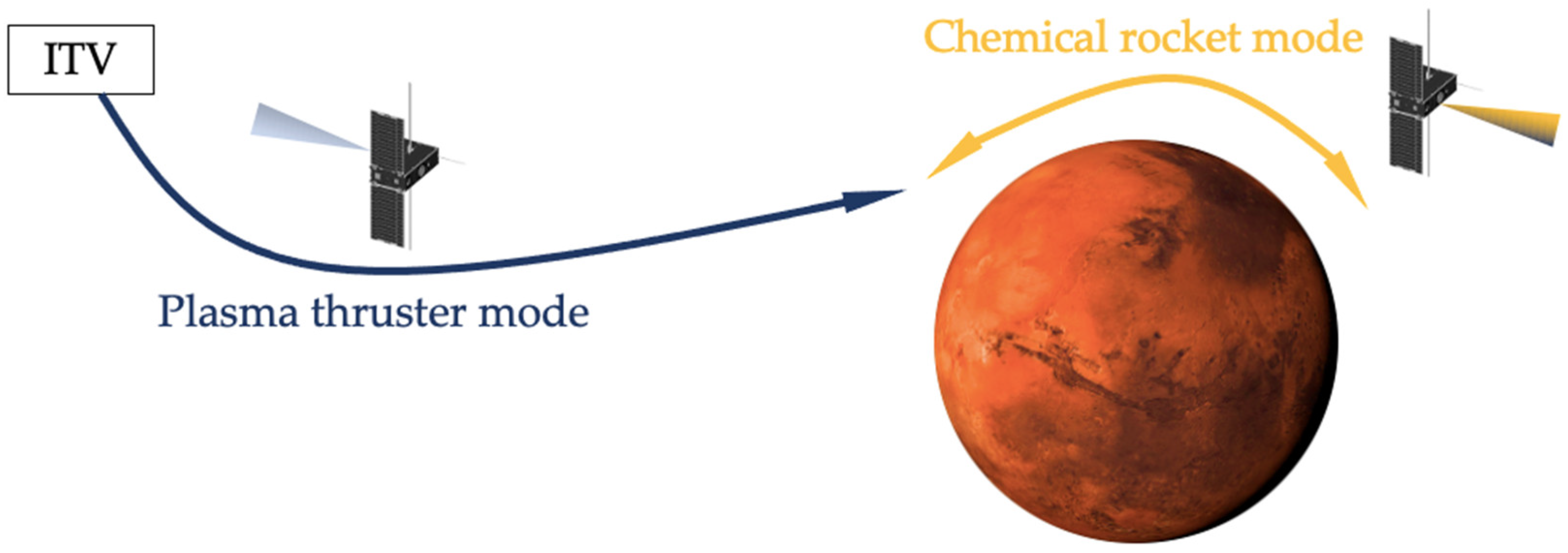
This multimode thruster utilizing magnesium as the propellant can be used onboard small satellites that, for example, provide intermittent communication services on the surface of Mars (see Figure 6).
The plasma thruster mode can be used for transferring the small satellite from the interplanetary transportation vehicle (ITV) to the target orbit of Mars. Also, the plasma thruster mode can be used for the altitude control of such spacecrafts at high altitude orbits, and then when signal provision is needed, the satellite can descend and ascend by using the chemical rocket engine mode utilizing the residual atmosphere of Mars as the oxidizer and the magnesium stored onboard as the fuel. For example, assuming the use of a 16U satellite where the propulsion system takes 4U volume with the capability of accelerating the propellant to the effective velocity of up to 10,000 m/s, it will be possible to store onboard 1 kg of the magnesium propellant using the electrodeless plasma thruster. The dry mass of the satellite is assumed to be 16 kg. Thus, the estimated characteristic velocity, Δ V , is 630 m/s.

5. Conclusions

The investigated propellants each possess specific advantages and drawbacks. For small satellite applications, it is optimal to use propellants with high storage density, while the energy required for their vaporization, including thermal stabilization, must be minimized due to the limited onboard power resources. It is also crucial that the vapor of the selected propellant does not pose hazards during ground testing and in-space operations. Failure to meet these requirements can significantly increase the mission costs and risks.
Another key criterion is the chemical inertness of the propellant in a solid state, as it must not react with spacecraft components, including after being deposited as films on the surfaces of spacecrafts. A comprehensive investigation has identified a set of propellants—iodine, magnesium, zinc, and bismuth—that are the most promising alternative propellants. The use of cesium is associated with elevated risks and technical challenges, particularly in the synthesis of intermetallic compounds.
For some near-term dynamic missions to be developed that include operations in the Mars orbit, magnesium demonstrates several favorable properties. It has relatively high storage density, elevated saturated vapor pressure, relatively low ionization potential, and is considered relatively safe for ground operations due to its low toxicity. The atomic mass of magnesium vapor is sufficiently high for efficient acceleration in thrusters with electrostatic and electromagnetic mechanisms of acceleration. The main drawback is the potential for thin film deposition, which must be mitigated through methods such as surface passivation or localized heating of critical components during thruster operations.
For deep space dynamic missions of small satellites, it is proposed to use the wire-based solid-state propellant system. In comparison to other solid-state propellant management systems, it has advantageous features such as a reduced overall volume occupied by the system and enhanced precision and responsiveness of flow rate control. The use of the propellant in the form of wire allows for minimizing the physical dimensions of the system. Flow rate accuracy is achieved by improving the accuracy of controlling propellant flow rates using a magnetohydrodynamic pump. Energy efficiency is achieved by a decrease in the sublimation zone dimensions.

Author Contributions

Conceptualization, P.O.S. and A.I.S.; methodology, P.O.S. and A.I.S.; software, P.O.S.; validation, P.O.S., A.I.S. and V.D.T.; formal analysis, P.O.S.; investigation, P.O.S. and A.I.S.; resources, A.I.S.; data curation, P.O.S. and A.I.S.; writing—original draft preparation, P.O.S. and A.I.S.; writing—review and editing, P.O.S. and A.I.S.; visualization, P.O.S. and A.I.S.; supervision, A.I.S.; project administration, A.I.S.; funding acquisition, A.I.S. All authors have read and agreed to the published version of the manuscript.

Funding

This work is funded by the government task by the Ministry of Science and Higher Education of the Russian Federation (FSFN-2024-0007).

Data Availability Statement

The data that support this study are available from the corresponding author upon reasonable request.

Conflicts of Interest

The authors declare no conflicts of interest.

References

  1. Alnaqbi, S.; Darfilal, D.; Swei, S.S.M. Propulsion Technologies for CubeSats. Aerospace 2024, 11, 502. [Google Scholar] [CrossRef]
  2. Ponti, F. Advancing Iodine Thruster Technology: Insights and Objectives of Project BOOST. J. Electr. Propuls. 2025, 4, 41. [Google Scholar] [CrossRef]
  3. Levchenko, I.; Baranov, O.; Keidar, M.; Riccardi, C.; Roman, H.E.; Xu, S.; Alexander, K. Additive Technologies and Materials for the Next-Generation CubeSats and Small Satellites. Adv. Funct. Mater. 2024, 34, 2407602. [Google Scholar] [CrossRef]
  4. Shumeiko, A.; Telekh, V.; Ryzhkov, S. Thrust-Vectoring Schemes for Electric Propulsion Systems: A Review. Chin. Chin. Chin. Chin. J. Aeronaut. 2025, 38, 103401. [Google Scholar] [CrossRef]
  5. O’Reilly, D.; Herdrich, G.; Kavanagh, D.F. Electric Propulsion Methods for Small Satellites: A Review. Aerospace 2021, 8, 22. [Google Scholar] [CrossRef]
  6. Savelev, P.O.; Pashaev, A.D.; Shumeiko, A.I. Modeling of Processes in Porous Thermal Throttles for Iodine Flow Control for Space Applications. Results Eng. 2024, 24, 103463. [Google Scholar] [CrossRef]
  7. Rafalskyi, D.; Martínez, J.M.; Habl, L.; Rossi, E.Z.; Proynov, P.; Boré, A.; Baret, T.; Poyet, A.; Lafleur, T.; Dudin, S.; et al. In-Orbit Demonstration of an Iodine Electric Propulsion System. Nature 2021, 599, 411–415. [Google Scholar] [CrossRef]
  8. Bellomo, N.; Magarotto, M.; Manente, M.; Trezzolani, F.; Mantellato, R.; Cappellini, L.; Paulon, D.; Selmo, A.; Scalzi, D.; Minute, M.; et al. Design and In-Orbit Demonstration of REGULUS, an Iodine Electric Propulsion System. CEAS Space J. 2022, 14, 79–90. [Google Scholar] [CrossRef]
  9. Levchenko, I.; Goebel, D.M.; Bazaka, K. Electric Propulsion of Spacecraft. Phys. Today 2022, 75, 38–44. [Google Scholar] [CrossRef]
  10. Levchenko, I.; Baranov, O.; Pedrini, D.; Riccardi, C.; Roman, H.E.; Xu, S.; Lev, D.; Bazaka, K. Diversity of Physical Processes: Challenges and Opportunities for Space Electric Propulsion. Appl. Sci. 2022, 12, 11143. [Google Scholar] [CrossRef]
  11. Shumeiko, A.I.; Telekh, V.D.; Ryzhkov, S.V. Probe Diagnostics and Optical Emission Spectroscopy of Wave Plasma Source Exhaust. Symmetry 2022, 14, 1983. [Google Scholar] [CrossRef]
  12. Shumeiko, A.I.; Telekh, V.D.; Mayorova, V.I. Development of a Novel Wave Plasma Propulsion Module with Six-Directional Thrust Vectoring Capability. Acta Astronaut. 2022, 191, 431–437. [Google Scholar] [CrossRef]
  13. Takahashi, K.; Charles, C.; Boswell, R.W. Detection of High Energy Electrons in a Cusp-Field Magnetic Nozzle Radio Frequency Plasma Thruster. AIP Adv. 2025, 15, 075203. [Google Scholar] [CrossRef]
  14. Andrews, S.; Andriulli, R.; Souhair, N.; Magarotto, M.; Ponti, F. Axial-Radial Plasma Transport and Performance of a Plasma Thruster Magnetic Nozzle under Bohm’s Anomalous Diffusion Scaling. Plasma Sources Sci. Technol. 2025, 30, 015013. [Google Scholar] [CrossRef]
  15. Andreescu, A.M.T.; Crunteanu, D.E.; Teodorescu, M.V.; Danescu, S.N.; Stoicescu, A.; Cancescu, A.; Paraschiv, A. Operating Characteristics of a Wave-Driven Plasma Thruster for Cutting-Edge Low Earth Orbit Constellations. Inventions 2024, 9, 107. [Google Scholar] [CrossRef]
  16. Shumeiko, A.I.; Telekh, V.D. Direct Thrust Measurements of 2U-Sized Bi-Directional Wave Plasma Thruster. AIP Adv. 2023, 13, 085113. [Google Scholar] [CrossRef]
  17. Shumeiko, A.I.; Telekh, V.D.; Ryzhkov, S.V. Starting Modes of Bi-Directional Plasma Thruster Utilizing Krypton. Symmetry 2023, 15, 1705. [Google Scholar] [CrossRef]
  18. Andronov, A.A.; Shumeiko, A.I.; Pashaev, A.D.; Tsygankov, P.A.; Kovalev, S.V.; Telekh, V.D. Plume Characterization of Electrodeless Plasma Thruster with Configurable Exhaust. Symmetry 2025, 17, 661. [Google Scholar] [CrossRef]
  19. Andrews, S.; Andriulli, R.; Souhair, N.; Magarotto, M.; Ponti, F. Cathode-Less RF Plasma Thruster Design and Optimisation for an Atmosphere-Breathing Electric Propulsion (ABEP) System. Acta Astronaut. 2024, 225, 833–844. [Google Scholar] [CrossRef]
  20. van Lynden, W.; Andriulli, R.; Souhair, N.; Ponti, F.; Magarotto, M. Coupling of Fluid and Particle-In-Cell Simulations of Ambipolar Plasma Thrusters. Aerospace 2024, 11, 880. [Google Scholar] [CrossRef]
  21. Shumeiko, A.I.; Telekh, V.D. Helicon Engine in Outboard Air as a Successful Solution for Maintaining Small Space Vehicle in Orbits Up to 200 km. In Proceedings of the AIP Conference, Moscow, Russia, 28 January–1 February 2019; AIP Publishing LLC.: Melville, NY, USA, 2019; p. 170019. [Google Scholar]
  22. Yamasaki, J.; Yokota, S.; Shimamura, K. Hall thruster performances using low cost propellant. In Proceedings of the AIAA Propulsion and Energy 2019 Forum, Indianapolis, IN, USA, 19–22 August 2019; p. 3999. [Google Scholar] [CrossRef]
  23. Martínez, J.; Rafalskyi, D. Design and development of iodine flow control systems for miniaturized propulsion systems. CEAS Space J. 2022, 14, 91–107. [Google Scholar] [CrossRef]
  24. Benavides, G.F.; Kamhawi, H.; Mackey, J.; Haag, T.; Costa, G. Iodine Hall-effect electric propulsion system research, development, and system durability demonstration. In Proceedings of the 2018 Joint Propulsion Conference, Cincinnati, OH, USA, 9–11 July 2018; p. 4422. [Google Scholar]
  25. Tsay, M.; Frongillo, J.; Zwahlen, J.; Paritsky, L. Maturation of iodine fueled BIT-3 RF ion thruster and RF neutralizer. In Proceedings of the 52nd AIAA/SAE/ASEE Joint Propulsion Conference, Salt Lake City, UT, USA, 25–27 July 2016; p. 4544. [Google Scholar] [CrossRef]
  26. Foust, J. Cubesat Launched on Artemis 1 Trying to Fix Propulsion System. SpaceNews.com. Available online: https://spacenews.com/cubesat-launched-on-artemis-1-trying-to-fix-propulsion-system/ (accessed on 16 August 2025).
  27. Yaginuma, K.; Asakawa, J.; Nakagawa, Y.; Tsuruda, Y.; Koizumi, H.; Kakihara, K.; Yanagida, K.; Murata, Y.; Ikura, M.; Matsushita, S.; et al. AQT-D: CubeSat demonstration of a water propulsion system deployed from ISS. Trans. Jpn. Soc. Aeronaut. Space Sci. Aerosp. Technol. Jpn. 2020, 18, 141–148. [Google Scholar] [CrossRef]
  28. Bruno, T.J.; Svoronos, P.D. CRC Handbook of Fundamental Spectroscopic Correlation Charts; CRC Press: Boca Raton, FL, USA, 2005. [Google Scholar]
  29. Grishin, S.D.; Leskov, L.V.; Kozlov, N.P. Electric Rocket Engines; Nauka: Moscow, Russia, 1975. [Google Scholar]
  30. Szabo, J.; Robin, M.; Paintal, S.; Pote, B.; Hruby, V. High density Hall thruster propellant investigations. In Proceedings of the 48th AIAA/ASME/SAE/ASEE Joint Propulsion Conference & Exhibit, Atlanta, GA, USA, 30 July–1 August; 2012. [Google Scholar] [CrossRef]
  31. Lide, D.R. CRC Handbook of Chemistry and Physics: A Ready-Reference Book of Chemical and Physical Data; CRC Press: Boca Raton, FL, USA, 2018. [Google Scholar]
  32. Younglove, B. Tables of Industrial Gas Container Contents and Density for Oxygen, Argon, Nitrogen, Helium, and Hydrogen; National Bureau of Standards: Washington, DC, USA, 1985. [Google Scholar]
  33. Stull, D.R. Vapor pressure of pure substances. Organic and inorganic compounds. Ind. Eng. Chem. 1947, 39, 517–540. [Google Scholar] [CrossRef]
  34. Teng, Y.; Li, Z.; Chen, C. Pre-Darcy Flows in Low-Permeability Porous Media. Hydrogeol. J. 2024, 32, 1957–1977. [Google Scholar] [CrossRef]
  35. Koutsoyiannis, D. Clausius–Clapeyron Equation and Saturation Vapour Pressure: Simple Theory Reconciled with Practice. Eur. J. Phys. 2012, 33, 295. [Google Scholar] [CrossRef]
  36. Szabo, J.J., Jr.; Pote, B.; Paintal, S.; Robin, M.; Hruby, V. Iodine Fueled Plasma Generator System. Patent No. US8610356B2, 17 December 2013. [Google Scholar]
  37. Alekseevich, B.A.; Aleksandrovich, K.S.; Georgievich, O.V.; Alekseevich, S.A.; Aleksandrovich, S.P. Iodine Storage and Supply System. Patent No. RU2557789C2, 27 July 2015. [Google Scholar]
  38. Olegovich, S.P.; Dzhamaldinovich, P.A.; Ivanovich, S.A. System for Storage and Supply of Working Medium with Possibility of Fast Flow Control. Patent No. RU2828141C1, 7 October 2024. [Google Scholar]
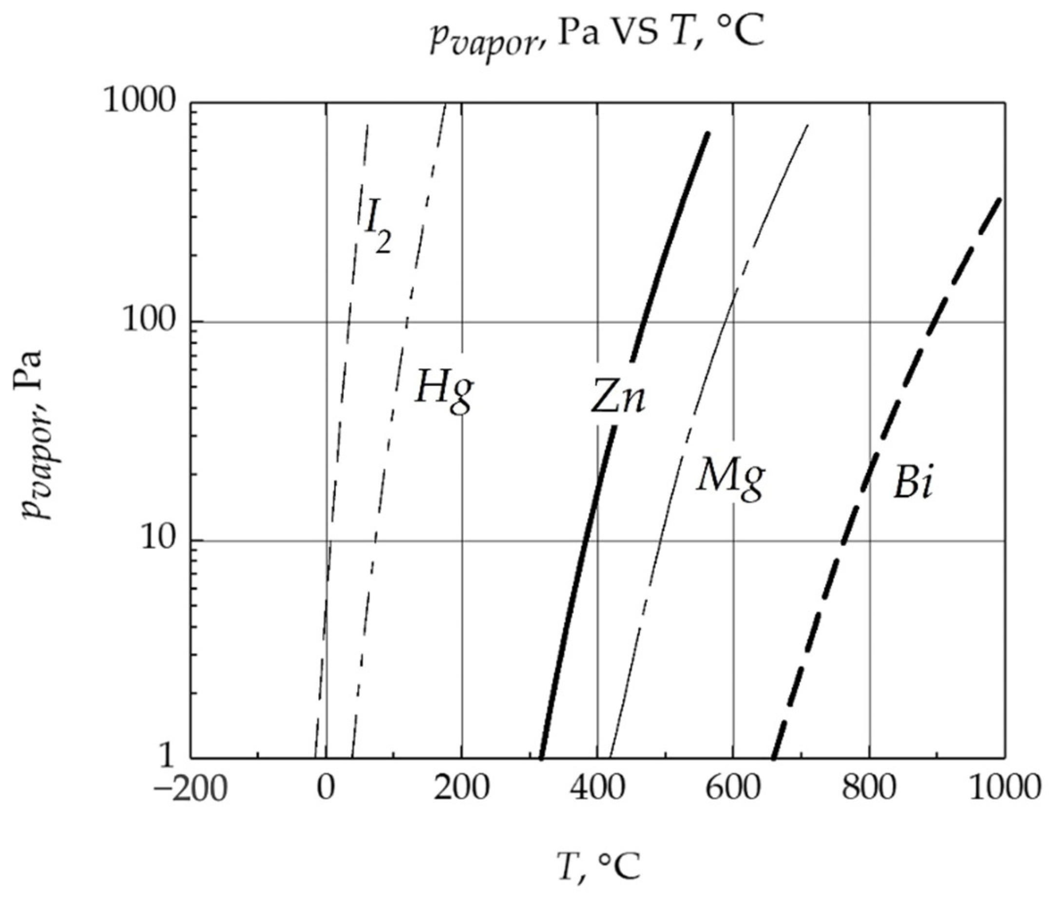
Figure 1. Saturated vapor pressure of alternative propellants.
Inventions 10 00075 g001
Figure 2. Scheme of proposed PSSS: 1—propellant storage tank; 2—propellant; 3—tank heater; 4—MHD pump; 5—first thermal throttle; 6—second thermal throttle; 7—nozzle fitting; 8—primary feed system; equipped with a spring mechanism or a servo drive; 9—second thermal throttle heater; 10—first thermal throttle heaters; 11—EMV; 12—third thermal throttle; 13—third thermal throttle heater; 14—third thermal throttle temperature sensor; 15—second thermal throttle temperature sensor; 16—first thermal throttle temperature sensor; 17—tank heater temperature sensor; 18—control unit; 19—heat exchanger.
Inventions 10 00075 g002
Figure 3. Dependence of volumetric flow rate of liquid zinc through first thermal throttle from pressure at temperature of 700 K.
Inventions 10 00075 g003
Figure 4. Zinc evaporation rate per unit volume versus temperature in sublimation zone.
Inventions 10 00075 g004
Figure 5. Scheme of multimode propulsion system using proposed propellant management system: (a)—chemical rocket engine mode; (b)—electrodeless plasma thruster mode. In figure, positions are as follows: 1—gas discharge chamber; 2—magnetic system; 3—inductor; 4—nozzle; 5—wire-based solid-state propellant management system.
Inventions 10 00075 g005
Figure 6. Concept of operation of small satellite equipped with propulsion system using wire-based solid-state propellant management system.
Inventions 10 00075 g006
Table 1. Comparative analysis of fluid- and solid-states propellant storage and supply systems for small satellites.
ParameterPressurized Fluid-State PSSSLiquid- and Solid-State PSSS
Propellant typeNoble gases (Kr, Xe, Ar)Solids (I2, Zn, Mg, Bi, Hg, Cs) or liquids (H2O, NH3)
Aggregation stateGaseous- or liquid-state substancesLiquid- and solid-state substances
Storage conditionsPressures in range from 100 kPa to dozens MPa, temperatures in range from −60 °C to 60 °CPressures in range of 1 to 100 kPa, temperatures in range of −60 °C to 103 °C
Mass flow and pressure management systemHigh-pressure valves and throttles with given flow areaLow-pressure valves, thermal throttles in form of porous filters and tubes with given flow cross-section that includes heating system
Storage density, (g/cm3)<2Up to 10
DimensionsDry mass and volume up to 90% of whole propulsion systemDry mass and volume no more than 50% of whole propulsion system
RisksPropellant tanksDepressurizationChemical destruction
Feedthrough linesDepressurization, clogging due to system or propellant impurities (metal swarf)Channel blockage due to deposited propellant accumulation [26]
Satellite systems and componentsNoneDeposition of propellant on systems and components of satellite
Applicability for CubeSatsLimited due to mass and volumeVersatile, depending on choice of propellant
Thermal controlPropellant preparationNot requiredRequired for sublimation
TanksNot required except for XeRequired during operations
LinesNor requiredRequired during operations
Some flight application examples on small satellites, thruster name (propellant)BDEPT (Kr) [4]NPT-30 (I2) [7]
Regulus (I2) [8]
BIT-3 (I2) [25]
AQT-D (H2O) [27]
Table 2. Propellant characteristics related to use in propulsion systems.
PropellantStorage Density, (g/cm3)Potential Ionization, (eV)Temperature, (K) at Which Pressure of 1000 (Pa) Is ReachedMolar Mass, (g/mol)Notes on Safety and Operating Conditions
I24.99.3341.681271
Zn7.19.4448652
Mg1.747.7698242
Bi9.787.310522092
Cs1.933.93501321,3
Kr0.514-83-
Xe1.612.1-1314
1 Iodine is a chemically aggressive substance that may induce corrosion, particularly in certain metals, and cause embrittlement of some polymers and elastomeric materials. Exposure to iodine vapor should be avoided when the thruster is not in operation. 2 Under specific conditions, the substance may condense and accumulate on satellite surfaces. 3 Cesium is an extremely reactive metal; its use requires strict safety precautions and specialized containment measures to ensure safe handling and operation. 4 Xenon undergoes a phase transition at a pressure of 10–12 atm near 4 °C; therefore, PSSSs utilizing xenon require integrated thermal control to ensure stable operation.
Disclaimer/Publisher’s Note: The statements, opinions and data contained in all publications are solely those of the individual author(s) and contributor(s) and not of MDPI and/or the editor(s). MDPI and/or the editor(s) disclaim responsibility for any injury to people or property resulting from any ideas, methods, instructions or products referred to in the content.