Implementation of an Academic Learning Module for CNC Manufacturing Technology of the Part ”Double Fixing Fork”
Abstract
1. Introduction
2. Materials and Methods
2.1. Part Analysis
- Operation 1. Roughing milling
- Phases:
- 1.1.
- Side face milling—3, 4, 30, 31
- 1.2.
- Face milling—7, 8, 29
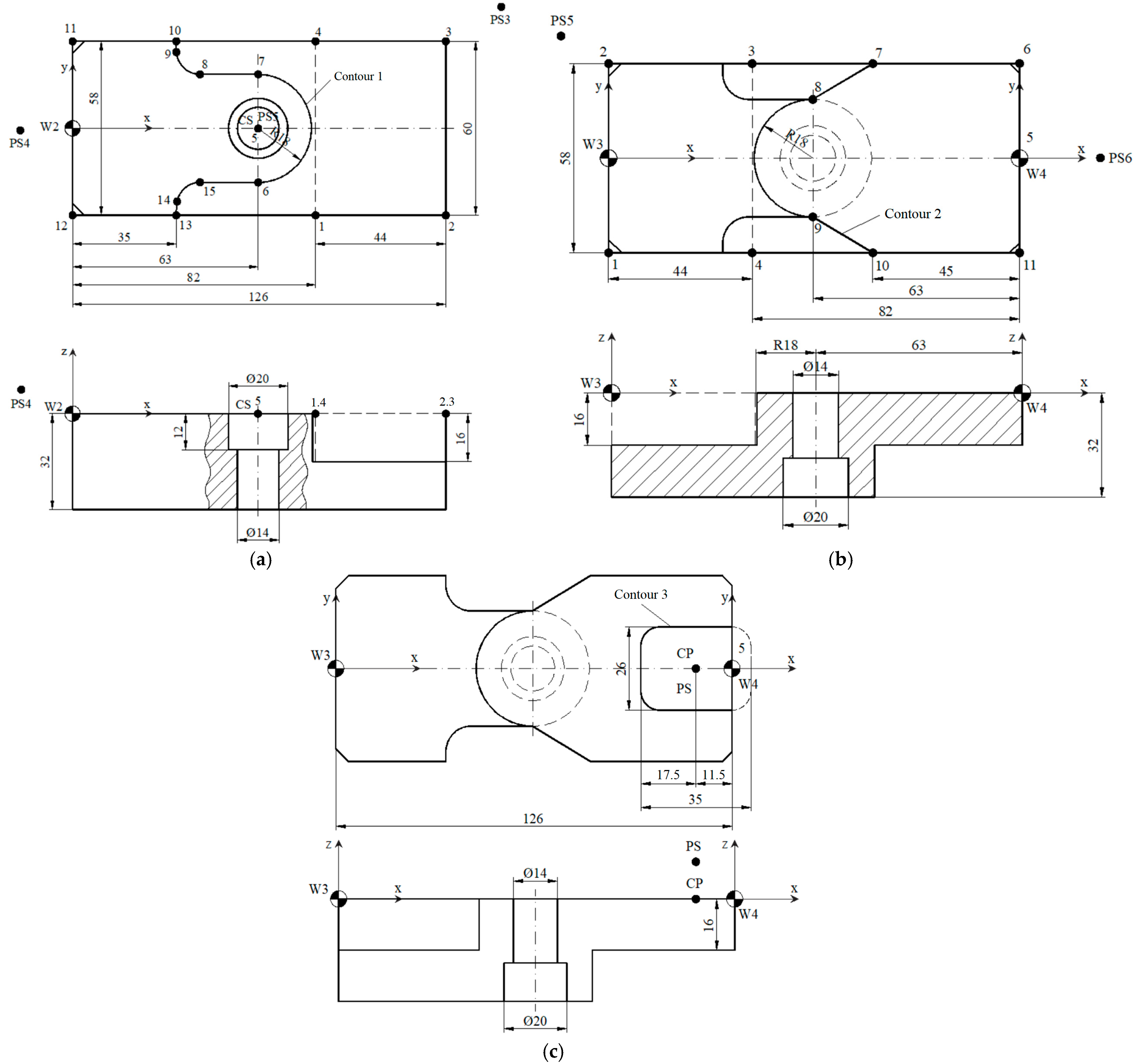
- Operation 2. Contour milling 1
- Phases:
- 2.1.
- Cylindrical face milling—2
- 2.2.
- Contour profile milling 1—27, 28, 29, 30, 31, 37
- 2.3.
- Center drilling—13
- 2.4.
- Drilling—13
- 2.5.
- Counterboring—13, 36
- Operation 3. Contour milling 2 and 3
- Phases:
- 3.1.
- Cylindrical face milling—25, 262
- 3.2.
- Contour milling 2—5, 6, 7, 8, 9, 10, 123
- 3.3.
- Contour milling 3—11
- Operation 4. Drilling
- Phases:
- 4.1.
- Center drilling—14, 15, 16, 17, 18, 19, 20
- 4.2.
- Drilling—14, 15, 16
- 4.3.
- Drilling—17, 18, 19, 20
- 4.4.
- Counterboring—17, 18, 19, 20
- 4.5.
- Threading—14, 15, 16
- Operation 5. Milling and drilling
- Phases:
- 5.1.
- Channel milling—34, 35
- 5.2.
- Center drilling—32, 33
- 5.3.
- Drilling—32, 33
2.2. Technological Regime Elements
- -
- In the case of milling and counterboring operations:
- -
- In the case of center drilling operations:
- -
- In the case of drilling operations:
- -
- In the case of threading operations:
2.3. Structure of CNC Technology
3. Results
4. Discussion
5. Conclusions
Author Contributions
Funding
Data Availability Statement
Acknowledgments
Conflicts of Interest
References
- Sandor, R.N.; Pop, A.B.; Titu, A.M. Design and validation of a fixture device for machining surfaces with barrel end-mill on a 3-axis CNC milling machine. Appl. Sci. 2025, 15, 7379. [Google Scholar]
- Yan, X. Research and application of CNC machining method based on CAD/CAM/robot integration. Adv. Multimed. 2022, 2022, 5397369. [Google Scholar] [CrossRef]
- Gołebski, R. Parametric programming of CNC machine tools. MATEC Web Conf. 2017, 94, 07004. [Google Scholar] [CrossRef]
- Bhattacharyya, B.; Doloi, B. Modern Machining Technology. Advanced, Hybrid, Micro Machining and Super Finishing Technology; Academic Press: Cambridge, MA, USA, 2019; pp. 1–780. ISBN 978-012-812-894-7. [Google Scholar]
- Nguyen, D.K.; Huang, H.C.; Feng, T.C. Prediction of thermal deformation and real-time error compensation of a CNC milling machine in cutting processes. Machines 2023, 11, 248. [Google Scholar] [CrossRef]
- José, M.I.K.; Óscar, H.U.; Leonor, A.C.R.; Ramón, A.L.M. Extended reality applications for CNC machine training: A systematic review. Multimodal Technol. Interac. 2024, 8, 80. [Google Scholar]
- Baroiu, N.; Moroșanu, G.A.; Teodor, V.G.; Nedelcu, D.; Tăbăcaru, V. Prediction of surface roughness in drilling of polymers using a geometrical model and artificial neural networks. Mat. Plast. 2020, 57, 160–173. [Google Scholar] [CrossRef]
- Roman, O.; Trae, S.; Santiago, G.; Stanton, M.; Clumpner, B.; Hoyer, B.; Nowicki, M. Computer numerical control integration into the undergraduate mechanical engineering curriculum. In Proceedings of the ASME 2024 International Mechanical Engineering Congress and Exposition—IMECE2024, Portland, OR, USA, 17–21 November 2024. [Google Scholar]
- Petru, C.D.; Morariu, F.; Breaz, R.E.; Crenganis, M.; Racz, S.G.; Gîrjob, C.E.; Bârsan, A.; Biris, C.M. Development of a small CNC machining center for physical implementation and a digital twin. Appl. Sci. 2025, 15, 5549. [Google Scholar] [CrossRef]
- Baroiu, N.; Novac, G.; Tăbăcaru, V.; Moroșanu, G.A. The development cycle of machining operations on an educational CNC machine. Int. J. Ed. Inf. Technol. 2024, 18, 44–54. [Google Scholar] [CrossRef]
- Zahid, M.N.O.; Case, K.; Watts, D. End mill tools integration in CNC machining for rapid manufacturing processes: Simulation studies. Prod. Manuf. Res. 2015, 3, 274–288. [Google Scholar][Green Version]
- Vishaldeep, S.; Hitesh, A.; Prashant, K.P.; Rahul, W. A methodology for simulation and verification of tool path data for 3-AXIS and 5-AXIS CNC machining. Int. J. Mech. Eng. Techn. (IJME) 2018, 9, 450–461. [Google Scholar][Green Version]
- Mishra, S.; Mondal, G.; Kumarasamy, M. Development of low-cost CNC-milled PMMA microfluidic chips as a prototype for organ-on-a-chip and neurospheroid applications. Organoids 2025, 4, 13. [Google Scholar] [CrossRef]
- Carta, M.; Loi, G.; Mehtedi, M.; Buonadonna, P.; Aymerich, F. Improving surface roughness of FDM-printed parts throughCNC machining: A brief review. J. Comp. Sc. 2025, 9, 296. [Google Scholar] [CrossRef]
- Fountas, N.; Manolakos, D.; Vaxevanidis, N. Machinability assessment and multi-objective optimization of graphene nanoplatelets-reinforced aluminum matrix composite in dry CNC turning. Metals 2025, 15, 584. [Google Scholar] [CrossRef]
- Szadkowska, K.; Kepczak, N.; Stachurski, W.; Pawłowski, W.; Rosik, R.; Bechcinski, G.; Sikora, M.; Witkowski, B.; Sikorski, J. Influence of machining parameters on the surface roughness and tool wear during slot milling of a polyurethane block. Materials 2025, 18, 193. [Google Scholar] [CrossRef] [PubMed]
- Shuling, Z.; Jie, B. Research on CNC programming and machining process based on CAD/CAM technology. App. Math. Non. Sci. 2024, 9, 1–18. [Google Scholar][Green Version]
- Martins, A.; Joao, L.; Costelha, H.; Neves, C. CNC machines integration in smart factories using OPC UA. J. Ind. Inf. Integr. 2023, 34, 100482. [Google Scholar] [CrossRef]
- Hongyi, W.; Xuanyi, W.; Xiaolei, D.; Hongyao, S.; Xinhua, Y. Review on design research in CNC machine tools based on energy consumption. Sustainability 2024, 16, 847. [Google Scholar]
- EMCO. Available online: https://www.emco-world.com/en/ (accessed on 15 June 2025).
- Siemens. Available online: https://cache.industry.siemens.com/dl/files/513/109481513/att_906053/v1/BHDsl_1015_ro-RO.pdf (accessed on 15 June 2025).
- Siemens. Available online: https://www.siemens.com/global/en/products.html (accessed on 16 June 2025).
- ICMIndustrie. Available online: https://www.icmindustrie.com/wp-content/uploads/2022/03/PEHD-1000-EN.pdf (accessed on 11 June 2025).
- Susac, F.; Tăbăcaru, V. Proiectarea dispozitivelor de prelucrare în construcţia de maşini. Bazele proiectării dispozitivelor de prelucrare. In Suport De Curs (Design of Machining Devices in Mechanical Engineering. Fundamentals of Machining Device Design. Course Material); Galati University Press: Galati, Romania, 2018; ISBN 978-606-696-127-1. [Google Scholar]
- Bučányová, M.; Riečičiarová, E. Specification of the component base for CNC processing centre EMCO Concept MILL 105. Appl. Mech. Mat. 2014, 693, 9–15. [Google Scholar]
- Wang, P.L.; Tsai, Y.T. Numerical analysis of CNC milling chatter using embedded miniature MEMS microphone array system. Inventions 2018, 3, 5. [Google Scholar] [CrossRef]
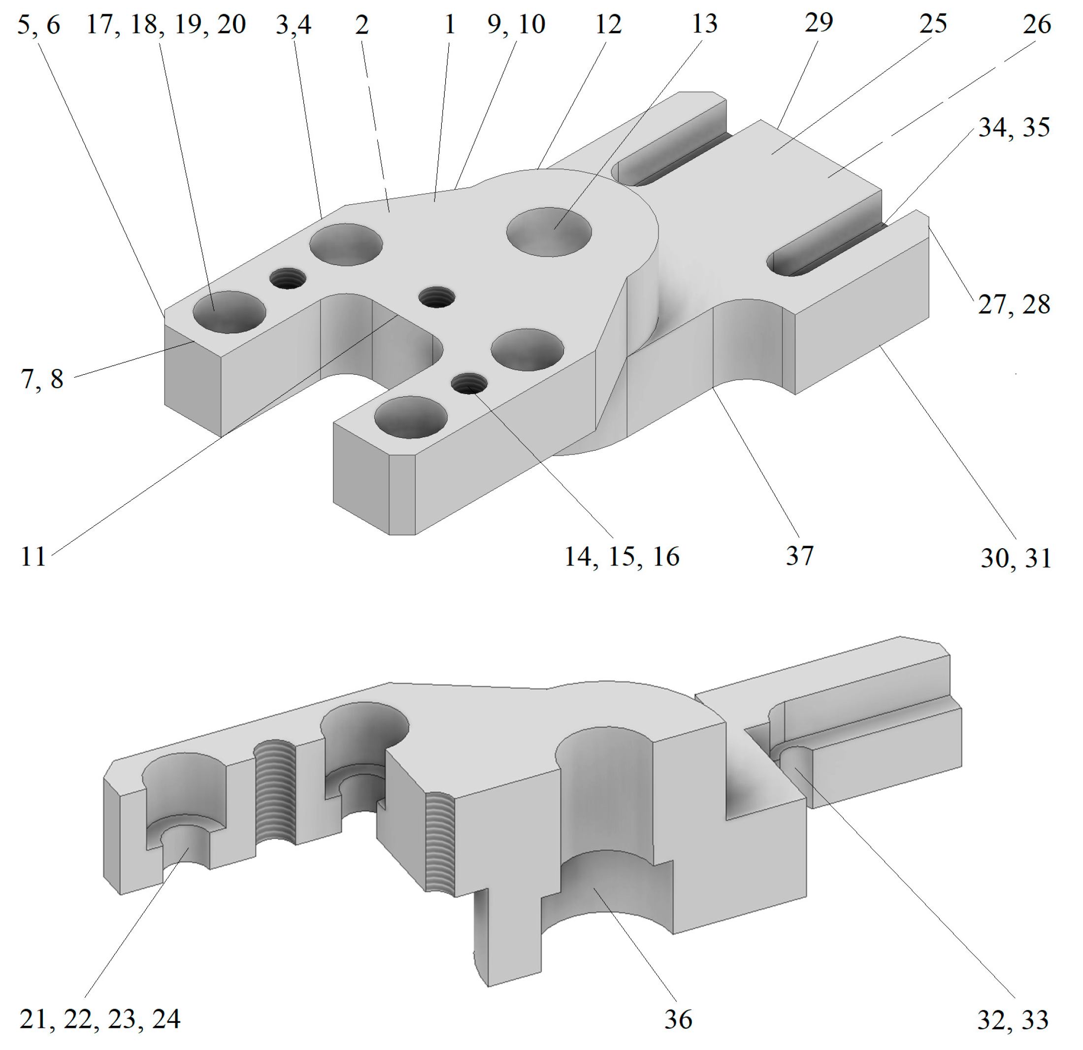


| Crt. no. | Surface Type | Code | Dimensions [mm] | Tolerances, TD [mm] | Roughness, Ra [μm] |
|---|---|---|---|---|---|
| 1. | Horizontal plane surface | SPO—01, 02 | 63 × 16 | - | 6.3 |
| 2. | Vertical plane surface | SPV—03, 04 | 45 × 16 | - | 3.2 |
| 3. | Vertical plane surface | SPV—05, 06 | 3 × 45° | - | - |
| 4. | Vertical plane surface | SPV—07, 08 | 16 × 16 | - | - |
| 5. | Inclined plane surface | SPΗ09, 10 | 21 × 16 | - | - |
| 6. | Vertical connected plane surface | SPRV—11 | 29 × 26 × 16/R6 | +0.11 0 | 3.2 |
| 7. | External cylindrical surface | SCE—12 | Ø36 × 16 | - | - |
| 8. | Inner cylindrical surface | SCI—13 | Ø14 × 20 | - | - |
| 9. | Inner helical cylindrical surface | SCEI—14, 15, 16 | 3 × M6 | - | - |
| 10. | Inner cylindrical surface | SCI—17, 18, 19, 20 | Ø11 × 10 | - | - |
| 11. | Inner cylindrical surface | SCI—21, 22, 23, 24 | Ø7 × 6 | - | - |
| 12. | Horizontal plane surface | SPO—25, 26 | 63 × 16 | - | 6.3 |
| 13. | Vertical plane surface | SPV—27, 28 | 4 × 45° | - | 6.3 |
| 14. | Vertical plane surface | SPV—29 | 58 × 16 | - | - |
| 15. | Vertical plane surface | SPV—30, 31 | 35 × 16 | - | 3.2 |
| 16. | Inner cylindrical surface | SCI—32, 33 | Ø5 × 9.5 | - | - |
| 17. | Horizontal plane surface | SPO—34, 35 | 25 × 6.5 | - | - |
| 18. | Inner cylindrical surface | SCI—36 | Ø20 × 12 | H8 | 3.2 |
| 19. | Connected profiled surface | SPR—37 | 28 × 16/R8/R18 | - | - |
| Phase | Processing Method | Workstation | Tool Type | Tool—Geometric Parameters [mm] | |||
|---|---|---|---|---|---|---|---|
| D | R | Lt | Ls | ||||
| 1.1 | Face milling | T7 | Cylindrical end mill | 14 | 7 | 20 | 70.98 |
| 1.2 | Face milling | T2 | Cylindrical end mill | 10 | 5 | 45 | 96.12 |
| 2.1 | Cylindrical face milling | T7 | Cylindrical end mill | 14 | 7 | 20 | 70.98 |
| 2.2 | Contour milling 1 CYCLE 72 | T7 | Cylindrical end mill | 14 | 7 | 20 | 70.98 |
| 2.3 | Center drilling CYCLE 81 | T8 | Center drill | 3 | - | 9 | 66.55 |
| 2.4 | Drilling | T7 | Helical drill | 10 | - | 38 | 84.83 |
| 2.5.a | Counterboring POCKET 2 | T2 | Cylindrical end mill | 10 | 5 | 45 | 96.12 |
| 2.5.b | Counterboring POCKET 2 | T2 | Cylindrical end mill | 10 | 5 | 45 | 96.12 |
| 3.1 | Cylindrical face milling | T7 | Cylindrical end mill | 14 | 7 | 20 | 70.98 |
| 3.2 | Contour milling 2 CYCLE 72 | T7 | Cylindrical end mill | 14 | 7 | 20 | 70.98 |
| 3.3 | Contour milling 3 POCKET 1 | T6 | Cylindrical end mill | 10 | 5 | 22 | - |
| 4.1 | Center drilling CYCLE 81 | T8 | Center drill | 3 | - | 9 | 66.55 |
| 4.2 | Drilling CYCLE 81 | T3 | Helical drill | 5 | - | 48 | - |
| 4.3 | Drilling CYCLE 81 | T2 | Helical drill | 7 | - | 31 | - |
| 4.4 | Counterboring CYCLE 89 | T4 | Counterbore | 12 | - | 26 | - |
| 4.5 | Threading CYCLE 840 | - | Metric tap | M6 | - | 40 | 85.30 |
| 5.1 | Channel milling | T5 | Channel mill | 8 | 4 | 13 | 90.15 |
| 5.2 | Center drilling | T8 | Center drill | 3 | - | 9 | 66.55 |
| 5.3 | Drilling | T3 | Helical drill | 5 | - | 48 | - |
| Yield Strength, σc [MPa] | Tensile Strength, σr [MPa] | Elongation at Break, ε [%] | Hardness HB | Elasticity Modulus, E [MPa] |
|---|---|---|---|---|
| 19 | 15 | >50 | 36 | 750 |
| Phase | Tool Type | Number of Teeth (z) | Basic Parameters | Programmable Parameters | ||||
|---|---|---|---|---|---|---|---|---|
| t [mm] | Sd [mm/rot] | Sb [mm/rot] | V [m/min] | S [rot/min] | F [mm/min] | |||
| 1.1 | Cylindrical end mill | 4 | 13 (32) | 0.06 | - | 25 | 568.69 | 136,48 |
| 1.2 | Cylindrical end mill | 4 | 13 (32) | 0.15 | - | 25 | 796.17 | 477,70 |
| 2.1 | Cylindrical end mill | 4 | 5 (16) | 0.15 | - | 25 | 568.69 | 314.21 |
| 2.2 | Cylindrical end mill | 4 | 4 (16) | 0.15 | - | 25 | 568.69 | 314.21 |
| 2.3 | Center drill | - | 2.5 | - | 0.30 | 25 | 2653.92 | 769.17 |
| 2.4 | Helical drill | - | 5 | - | 0.15 | 24 | 764.33 | 114.65 |
| 2.5.a | Cylindrical end mill | 4 | 4 (12) | 0.05 | - | 25 | 796.17 | 159.23 |
| 2.5.b | Cylindrical end mill | 4 | 2.5 (32) | 0.05 | - | 25 | 796.17 | 159.23 |
| 3.1 | Cylindrical end mill | 4 | 5 (16) | 0.15 | - | 25 | 568.69 | 314.21 |
| 3.2 | Cylindrical end mill | 4 | 4 (16) | 0.10 | - | 25 | 568.69 | 227.47 |
| 3.3 | Cylindrical end mill | 4 | 4 (16) | 0.10 | - | 25 | 568.69 | 227.47 |
| 4.1 | Center drill | - | 2.5 | - | 0.3 | 25 | 2653.92 | 769.17 |
| 4.2 | Helical drill | - | 3.5 | - | 0.1 | 25.28 | 1610.2 | 161.02 |
| 4.3 | Helical drill | - | 3.5 | - | 0.12 | 23.07 | 1049.59 | 125.95 |
| 4.4 | Counterbore | - | 6 | - | 0.16 | 24.39 | 647.29 | 103.56 |
| 4.5 | Metric tap | - | - | 0.75 | 4.48 | 238.29 | 178.72 | |
| 5.1 | Channel mill | 2 | 3 (6.5) | 0.013 | - | 25 | 995.22 | 25.87 |
| 5.2 | Center drill | - | 2.5 | - | 0.30 | 25 | 2653.92 | 769.17 |
| 5.3 | Helical drill | - | 2.5 | - | 0.10 | 25.28 | 1610.2 | 161.02 |
| W1 | Side Face Milling | PS1 | ||||
|---|---|---|---|---|---|---|
| 1 | 2 | 3 | 4 | |||
| X | 0 | 153 | 153 | 0 | −10 | |
| Y | 0 | 0 | 32 | 32 | 0 | |
| Z | −0.5 | −0.5 | −0.5 | −0.5 | 5 | |
| W1 | Face milling | PS2.1 | PS2.2 | |||
| 5 | 6 | 7 | 8 | |||
| X | 134 | 134 | 0 | 0 | −10 | 163 |
| Y | 0 | 60 | 0 | 60 | −10 | 70 |
| Z | −1 | −1 | −1 | −1 | 5 | 5 |
| W2 | Cylindrical Face Milling | Drilling—Counterboring | PS3 | PS4 | PS5 | CS | |||
|---|---|---|---|---|---|---|---|---|---|
| 1 | 2 | 3 | 4 | 5 | - | - | - | - | |
| X | 82 | 126 | 126 | 82 | 63 | 136 | −10 | 63 | 63 |
| Y | −29 | −29 | 29 | 29 | 0 | 40 | 0 | 0 | 0 |
| Z | −16 | −16 | −16 | −16 | −5—center drilling −35—drilling Ø10 (32 + 3) −33—counterboring Ø14 −12—counterboring Ø20 | 5 | 10 | 20 | - |
| W2 | Contour Milling 1 | |||||||||
|---|---|---|---|---|---|---|---|---|---|---|
| 6 | 7 | 8 | 9 | 10 | 11 | 12 | 13 | 14 | 15 | |
| X | 63 | 63 | 43 | 35 | 35 | 0 | 0 | 35 | 35 | 43 |
| Y | −18 | 18 | 18 | 26 | 29 | 29 | −29 | −29 | −26 | −18 |
| Z | −16 | −16 | −16 | −16 | −16 | −16 | −16 | −16 | −16 | −16 |
| W3 | Cylindrical Face Milling | PS5 | |||
|---|---|---|---|---|---|
| 1 | 2 | 3 | 4 | ||
| X | 0 | 0 | 44 | 44 | −10 |
| Y | −30 | 30 | −30 | 30 | 40 |
| Z | −15.8 | −15.8 | −15.8 | −15.8 | 5 |
| W4 | Contour Milling 2 | PS6 | ||||||
|---|---|---|---|---|---|---|---|---|
| 5 | 6 | 7 | 8 | 9 | 10 | 11 | ||
| X | 0 | 0 | −45 | −63 | −63 | −45 | 0 | 10 |
| Y | 0 | 29 | 29 | 18 | −18 | −29 | −29 | 0 |
| Z | −15.8 | −15.8 CHF=3 | −15.8 | −15.8 | −15.8 CR=18 | −15.8 | −15.8 CHF=3 | 5 |
| W4 | Contour Milling 3 | |
|---|---|---|
| PS | CP | |
| X | −11.5 | −11.5 |
| Y | 0 | 0 |
| Z | −18 | −18 |
| W4 | Drilling | |||||||
|---|---|---|---|---|---|---|---|---|
| PS7 | G1 | G2 | G3 | G4 | G5 | G6 | G7 | |
| X | 0 | −23.5 | −37 | −23.5 | −10 | −37 | −10 | −37 |
| Y | 0 | 21 | 0 | −21 | 21 | 21 | −21 | −21 |
| Z | 20 | −18.5 | −18.5 | −18.5 | −19/−10 | −19/−10 | −19/−10 | −19/−10 |
| W5 | Channel milling. Drilling | |||||||
| PS8 | CP1 | CP2 | G8 | G9 | ||||
| X | 0 | −6 | −6 | 21 | 21 | |||
| Y | 0 | 18 | −18 | 18 | −18 | |||
| Z | 20 | - | - | −8 −18.5 | −8 −18.5 | |||
| Program Block—BP | Tool | Workstation | Technological Phases |
|---|---|---|---|
| PROGRAM 1 | |||
| BP1 | Cylindrical end mill | D = 14 T7 | (a) Face milling, Phase 1.1 |
| BP2 | Cylindrical end mill | D = 10 T2 | (a) Face milling, Phase 1.2 |
| PROGRAM 2 | |||
| BP3 | Cylindrical end mill | D = 14 T7 | (a) Cylindrical face milling, Phase 2.1 (b) Contour milling 1, Phase 2.2 |
| BP4 | Center drill | D = 3 T8 | (a) Center drilling, Phase 2.3 |
| BP5 | Helical drill | D = 10 T7 | (a) Drilling, Phase 2.4 |
| BP6 | Cylindrical end mill | D = 10 T2 | (a) Counterboring, Phase 2.5.a |
| BP7 | Cylindrical end mill | D = 10 T2 | (a) Counterboring, Phase 2.5.b |
| PROGRAM 3 | |||
| BP8 | Cylindrical end mill | D = 14 T7 | (a) Cylindrical face milling, Phase 3.1 (b) Contour milling 2, Phase 3.2 |
| BP9 | Cylindrical end mill | D = 10 T6 | (a) Contour milling 3, Phase 3.3 |
| PROGRAM 4 | |||
| BP10 | Center drill | D = 3 T8 | (a) Center drilling, Phase 4.1 |
| BP11 | Helical drill | D = 5 T3 | (a) Drilling, Phase 4.2 |
| BP12 | Helical drill | D = 7 T2 | (a) Drilling, Phase 4.3 |
| BP13 | Counterbore | D = 12 T4 | (a) Counterboring, Phase 4.4 |
| BP14 | Metric tap | D = M6 T | (a) Threading, Phase 4.5 |
| PROGRAM 5 | |||
| BP15 | Channel mill | D = 8 T5 | (a) Channel milling, Phase 5.1 |
| BP16 | Center drill | D = 3 T8 | (a) Center drilling, Phase 5.2 |
| BP17 | Helical drill | D = 5 T3 | (a) Drilling, Phase 5.3 |
| Program Block | Technological Phase | Program Structure (Technological Lines) |
|---|---|---|
| BP1 | Face milling Phase 1.1 | G54 TRANS X-25 Y-32 Z40.5 T7 D1 M6 S568.69 M3 G0 Z-12 Y0 Z5 G1 X-10 Y0 Z0.5 F136.48 G1 X0 Y0 G1 X153 Y0 G1 X153 Y13 G1 X0 Y14 G1 X0 Y26 G1 X153 Y26 G1 X153 Y32 G1 X0 Y32 G0 X-10 Y0 Z5 G0 Z100 |
| …… | …… | …… |
| BP4 | Center drilling Phase 2.3 | T8 D1 M6 S2653.92 M3 F769.17 G0 X63 Y0 Z20 CYCLE81 (5, 0, 3, −7.5, 0) |
| …… | …… | …… |
| BP13 | Counterboring Phase 4.4 | T4 D1 M6 S647.29 M3 F103.56 G0 X0 Y0 Z20 MCALL CYCLE89 (5, 0, 3, −10, 0, 3) CYCLE801 (−37, −21, 0, 27, 42, 2, 2) MCALL Z100 |
| BP14 | Threading Phase 4.5 | T5 D1 M6 S238.29 M3 F178.72 G0 X0 Y0 Z20 MCALL CYCLE840 (5, 0, 3, −18.5, 0, 04, 3, 0, 0.75, 0, 3, 0, 0) CYCLE801 (−37, −21, 0, 27, 42, 2, 2) MCALL Z100 |
| …… | …… | …… |
| BP17 | Drilling Phase 5.3 | T3 D1 M6 S1610.2 M3 F161.02 G0 X0 Y0 Z20 CYCLE81 (5, 0, 3, −18.5, 0) G0 Y18 CYCLE81 (5, 0, 3, −18.5, 0) Z100 M30 |
| MOG C1 | MOG C2 |
|---|---|
| G1 X0 Y0 G1 X0 Y29 CHF=4 G1 X35 Y29 G1 X35 Y26 G3 X43 Y18 CR=8 G1 X63 Y18 G2 X63 Y-18 CR=18 G1 X43 Y-18 G3 X35 Y-26 CR=8 G1 X35 Y-29 G1 X0 Y-29 CHF=4 G1 X0 Y0 M17 | G1 X0 Y0 G1 X0 Y29 CHF=3 G1 X-45 Y29 G1 X-63 Y18 G3 X-63 Y-18 CR=18 G1 X-45 Y-29 G1 X0 Y-29 CHF=3 G1 X0 Y0 M17 |
Disclaimer/Publisher’s Note: The statements, opinions and data contained in all publications are solely those of the individual author(s) and contributor(s) and not of MDPI and/or the editor(s). MDPI and/or the editor(s) disclaim responsibility for any injury to people or property resulting from any ideas, methods, instructions or products referred to in the content. |
© 2025 by the authors. Licensee MDPI, Basel, Switzerland. This article is an open access article distributed under the terms and conditions of the Creative Commons Attribution (CC BY) license (https://creativecommons.org/licenses/by/4.0/).
Share and Cite
Moroşanu, G.-A.; Moroșanu, F.-I.; Susac, F.; Teodor, V.-G.; Păunoiu, V.; Baroiu, N. Implementation of an Academic Learning Module for CNC Manufacturing Technology of the Part ”Double Fixing Fork”. Inventions 2025, 10, 63. https://doi.org/10.3390/inventions10040063
Moroşanu G-A, Moroșanu F-I, Susac F, Teodor V-G, Păunoiu V, Baroiu N. Implementation of an Academic Learning Module for CNC Manufacturing Technology of the Part ”Double Fixing Fork”. Inventions. 2025; 10(4):63. https://doi.org/10.3390/inventions10040063
Chicago/Turabian StyleMoroşanu, Georgiana-Alexandra, Florin-Ioan Moroșanu, Florin Susac, Virgil-Gabriel Teodor, Viorel Păunoiu, and Nicuşor Baroiu. 2025. "Implementation of an Academic Learning Module for CNC Manufacturing Technology of the Part ”Double Fixing Fork”" Inventions 10, no. 4: 63. https://doi.org/10.3390/inventions10040063
APA StyleMoroşanu, G.-A., Moroșanu, F.-I., Susac, F., Teodor, V.-G., Păunoiu, V., & Baroiu, N. (2025). Implementation of an Academic Learning Module for CNC Manufacturing Technology of the Part ”Double Fixing Fork”. Inventions, 10(4), 63. https://doi.org/10.3390/inventions10040063


