Article

Implementation of an Academic Learning Module for CNC Manufacturing Technology of the Part ”Double Fixing Fork”

by
Georgiana-Alexandra Moroşanu
1,
Florin-Ioan Moroșanu
2,
Florin Susac
1,2,
Virgil-Gabriel Teodor
1,2,
Viorel Păunoiu
1,2 and
Nicuşor Baroiu
1,2,*
1
Research Center in Manufacturing Engineering Technology (ITCM), “Dunarea de Jos” University of Galati, 800201 Galati, Romania
2
Faculty of Engineering, ”Dunarea de Jos” University of Galati, 800008 Galati, Romania
*
Author to whom correspondence should be addressed.
Inventions 2025, 10(4), 63; https://doi.org/10.3390/inventions10040063
Submission received: 29 June 2025 / Revised: 22 July 2025 / Accepted: 28 July 2025 / Published: 29 July 2025
(This article belongs to the Section Inventions and Innovation in Advanced Manufacturing)

Abstract

The paper presents the CNC manufacturing technology of the ”Double fixing fork” part as a module with educational purpose, being designed as a training support for students and other parties, facilitating the practical learning of CNC processing technology. Its technological manufacturing process involved a careful analysis of the geometry, material, tolerances, as well as functional requirements to ensure precision and reliability in operation. The material from which the part was made is a polymer material (PEHD 1000) selected both for its mechanical characteristics and for its compatibility with processing technologies. The results demonstrated high precision and adaptability, reduced execution times and the possibility of achieving complex geometries in a relatively short time. The developed module supports skill development in CNC programming and operation and is suitable for replication in other academic environments. Programming allowed for more precise control of the cutting tool trajectory and processing parameters. The paper represents an important contribution to the training of future specialists, paying special attention to the growing interdisciplinarity in manufacturing technology and the development of technical skills necessary for future engineers in the numerically controlled machinery sector.

1. Introduction

In support of the fastest and most efficient processing of industrial products, numerous information storage systems in virtual environments have been developed. Coupled with the constant development of cutting tools and modern machine tools, they are capable of optimizing geometric and constructive parameters before the products are physically made. Computer numerical control—CNC machines—are those that streamline production processes through high precision, increased work capacity and shorter activity duration [1,2].
These require a high degree of operator expertise, but have a working interface that is easy to learn and use, offering the possibility to simulate the operation of the equipment. By automating the control of machine tool movements, CNC has revolutionized the machining processes, providing high precision, repeatability and efficiency in production. From milling and turning, to drilling or laser cutting, CNC is used in a variety of industries—from machine construction to the medical or aeronautical industry. One of its main advantages is the ability to produce complex geometries with minimal human intervention, thus reducing errors and increasing the quality of the finished product [3,4].
In recent years, with the evolution of materials, the use of polymers in CNC processes has become increasingly common. Polymeric materials, such as HDPE, POM, PVC or PMMA, are chosen for their high machinability, low weight and wear resistance. They offer the advantage of operational safety and are ideal for laboratory exercises, allowing the rapid production of parts, with minimal risk to operators and equipment. Compared to metallic materials, polymers exhibit different behavior during processing—they have a greater tendency for thermal deformation and require adapted cutting regimes. Therefore, the choice of appropriate technological parameters is important for obtaining quality parts [5,6,7].
In the specialized literature, more and more studies emphasize the importance of practical components in the training of engineers. The authors Roman O. et al. [8] addressed the issue of integrating CNC systems into the university curriculum, showing that access to such equipment allows students to better understand the CAD–CAM–CNC chain and promotes active learning. Petru C.D. et al. [9] developed a small-sized CNC machining center, using accessible controllers (Arduino, Pololu) and advanced simulations for calibrating axis movements. The proposed solution allows not only physical machining, but also digital replication, ideal for modern educational environments. Baroiu et al. [10], presented a machining cycle on an educational CNC machine, emphasizing the importance of going through all technological stages, from 3D modeling to programming and execution, offering students the complete experience in machining a reference with complex geometries.
On the simulation and optimization side, Zahid M.N.O. et al. [11] propose a methodology for integrating end mill tools into fast CNC processes, highlighting the benefits of simulation on part quality and reducing the volume of unprocessed material. Also, Vishaldeep S. et al. [12] propose a tool path verification and simulation system for three and five-axis CNC machining, using APIs in SolidWorks 2018 version 26 and ray tracing verification, which supports the idea of using simulation for CNC program validation, including for didactic purposes. Mishra S. [13] shows that CNC machining has been successfully adapted for medical applications (PMMA bio-chips), and Carta M. et al. [14] have demonstrated that CNC machining can improve the surface of parts obtained by FDM (fused deposition modeling).
Fountas N. et al. [15] explore the evaluation of machinability of graphene composite materials, while Szadkowska K. et al. [16] analyze the influence of machining regime on tool wear in polyurethane milling. Both studies provide useful insights for understanding the effects of materials and parameters on the CNC process.
Shuling Z. and Jie B. [17] proposed an approach to CNC programming using CAD/CAM integration, and Xiangsong Y. [2] extended this integration to include industrial robots. Martins A. et al. [18] presented the integration of CNC machines in smart factories using industrial protocols (OPC UA), highlighting the direction in which advanced technological training is heading. Hongyi W. et al. [19] conducted an analysis of CNC design from the perspective of energy consumption, and Gołebski R. [3] presented the advantages of CNC parametric programming for flexibility and efficiency.
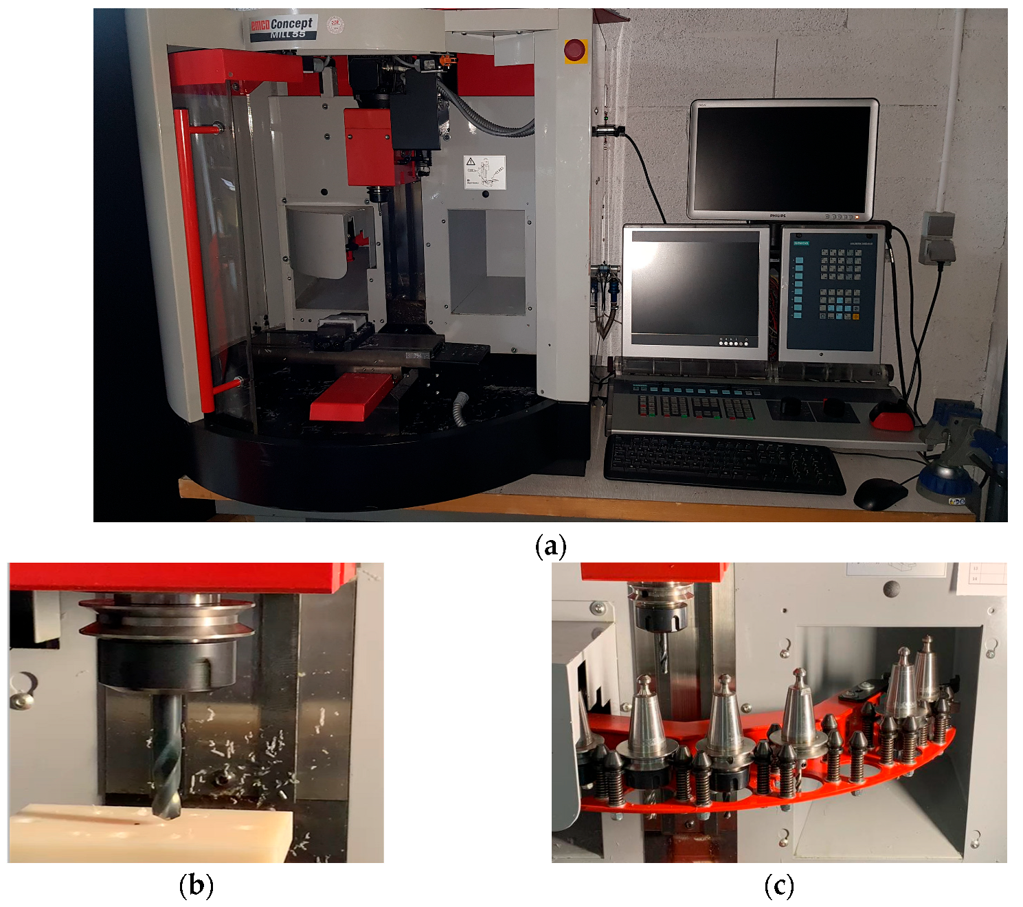
In this context, the paper proposes a practical application involving the use of a didactic CNC equipment, EMCO MILL 55 CNC, to create the ”Double fixing fork” reference, representative both in its geometry and in the chosen material. EMCO MILL 55 CNC is a three-axis numerical controlled machine, which allows the execution of small-sized parts (maximum 180 mm × 120 mm × 70 mm). It consists of three slides, the tool holder and the tool changer, Figure 1.
The slides allow movement on the x, y and z axes (x—worktable, y—worktable movement, z—main axis that allows tool change). The part is fixed on the tool holder, and depending on the difficulty of the part, it is chosen to be positioned directly on the flat bench vise or to be fixed. In order to fix the parts, rulers with seating surfaces larger than 60 × 60 mm are used directly on the machine’s worktable [1]. The tool clamping system of EMCO MILL 55 CNC equipment uses an SK30 cone clamping system, according to the DIN 2079 standard [20]. This system allows the mounting of various types of tools through dedicated tool holders, ensuring precise and secure fixation during the machining process.
For the control and operation of the EMCO Concept MILL 55 machine, an advanced CNC system, developed by Siemens—SINUMERIK 840 (Munich, Germany) [21]—is used. This is a high-performance CNC system, recognized for its flexibility and advanced capabilities in machine tool control. It also offers a robust hardware architecture and intelligent control algorithms, ensuring high dynamics and precision in machining. For the programming and operation of the machines, SINUMERIK 840 includes various technological functions such as advanced work cycles and transformations that simplify complex machining. At the same time, it supports programming in an advanced level language and according to DIN-ISO standard, offers flexibility in creating CNC programs [21,22].
The paper is part of the current efforts to integrate CNC technologies into the engineering educational process. Created for educational purposes, in the Research Center in Manufacturing Engineering Technology (ITCM), ”Dunarea de Jos” University of Galati, it aims to familiarize students with real manufacturing processes by developing a CNC machining technology of a part with relatively complex shape. This study also reflects a contribution to the formation of students’ applicative and analytical skills, emphasizing the technological understanding of the entire manufacturing process.

2. Materials and Methods

2.1. Part Analysis

The part from Figure 2 is called a ”Double fixing fork”.
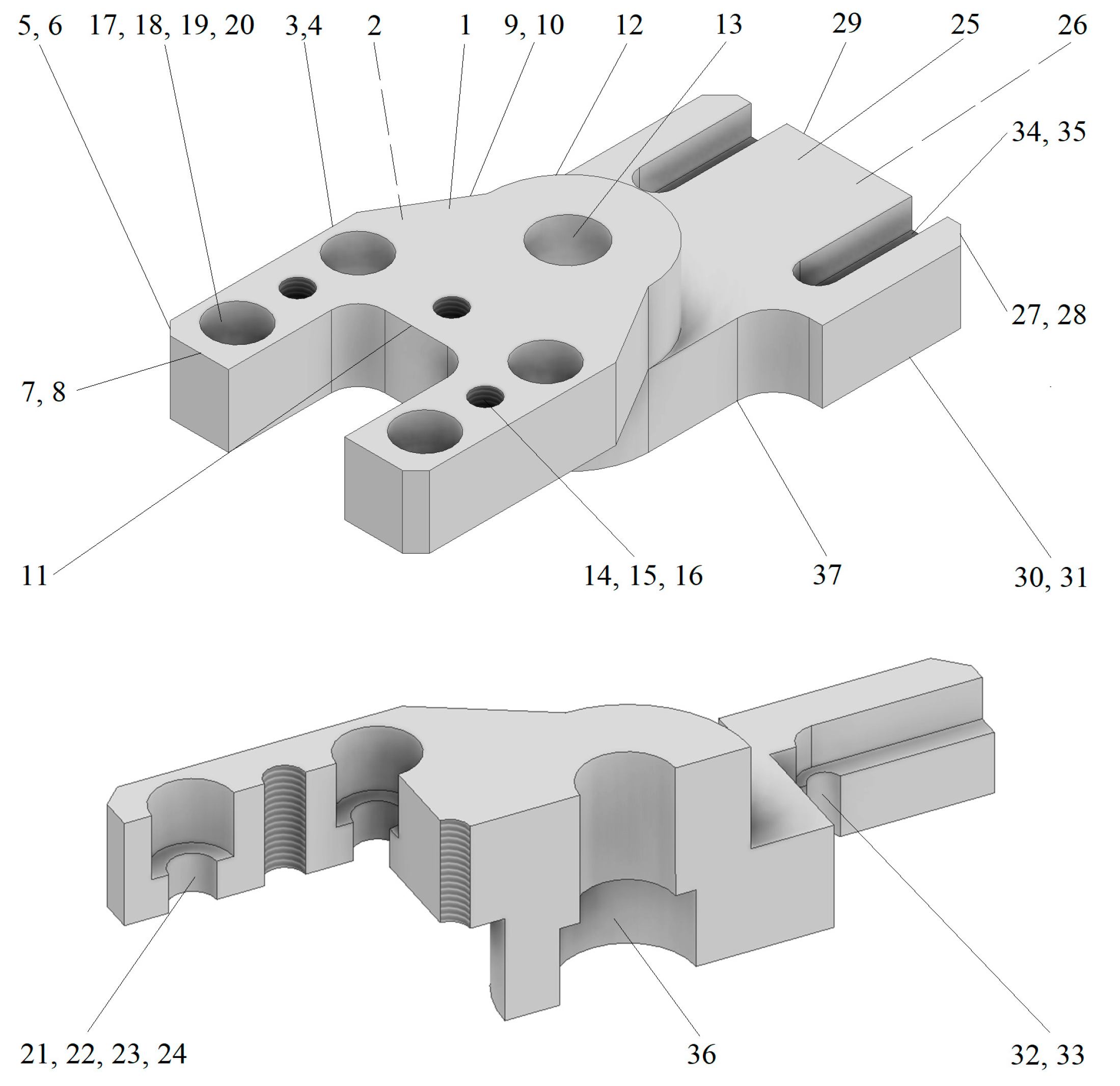
The types of surfaces of the part are presented in Figure 3 and Table 1. The part can be used in industrial machinery, clamping mechanisms or fixtures, both to clamp and guide components in a mechanism, ensuring their correct alignment and positioning.
The list of processing operations is as follows:
  • Operation 1. Roughing milling
  • Phases:
    1.1.
    Side face milling—3, 4, 30, 31
    1.2.
    Face milling—7, 8, 29
  • Operation 2. Contour milling 1
  • Phases:
    2.1.
    Cylindrical face milling—2
    2.2.
    Contour profile milling 1—27, 28, 29, 30, 31, 37
    2.3.
    Center drilling—13
    2.4.
    Drilling—13
    2.5.
    Counterboring—13, 36
  • Operation 3. Contour milling 2 and 3
  • Phases:
    3.1.
    Cylindrical face milling—25, 262
    3.2.
    Contour milling 2—5, 6, 7, 8, 9, 10, 123
    3.3.
    Contour milling 3—11
  • Operation 4. Drilling
  • Phases:
    4.1.
    Center drilling—14, 15, 16, 17, 18, 19, 20
    4.2.
    Drilling—14, 15, 16
    4.3.
    Drilling—17, 18, 19, 20
    4.4.
    Counterboring—17, 18, 19, 20
    4.5.
    Threading—14, 15, 16
  • Operation 5. Milling and drilling
  • Phases:
    5.1.
    Channel milling—34, 35
    5.2.
    Center drilling—32, 33
    5.3.
    Drilling—32, 33

2.2. Technological Regime Elements

Phases and processing methods of the part are presented in Table 2.
The part is made of a polymeric material—PEHD 1000 (high-density polyethylene (Ensinger GmbH, Nufringen, Germany) [23]), having the mechanical properties presented in Table 3. Also, the geometric parameters are presented in Table 4.
The cutting regime parameters—F, S, Sb, V—related to each machining phase are calculated with the following relationships:
-
In the case of milling and counterboring operations:
F = S d z S mm / min . ;
S = 1000 V π D rot / min . ,
-
In the case of center drilling operations:
S b = C s D mm / rot . ,
where Cs = 0.1 [24] and D = 3 mm.
F = S b S mm / min . .
-
In the case of drilling operations:
S b = K s C s D 0 , 6 mm / rot . ,
where the coefficients Ks = 1 and Cs = 0.038 are taken from [24].
V = K V K M D 0 , 4 S b 0 , 5 m / min . ,
where the coefficients KV = 3.7 and KM = 1 are taken from [24].
-
In the case of threading operations:
S b = p mm / rot . ,
where p represents the thread pitch.
V = K V M M 1 , 2 p 0 , 5 m / min . ,
where the coefficients KVM = 0.45 and M = 6 are taken from [24].

2.3. Structure of CNC Technology

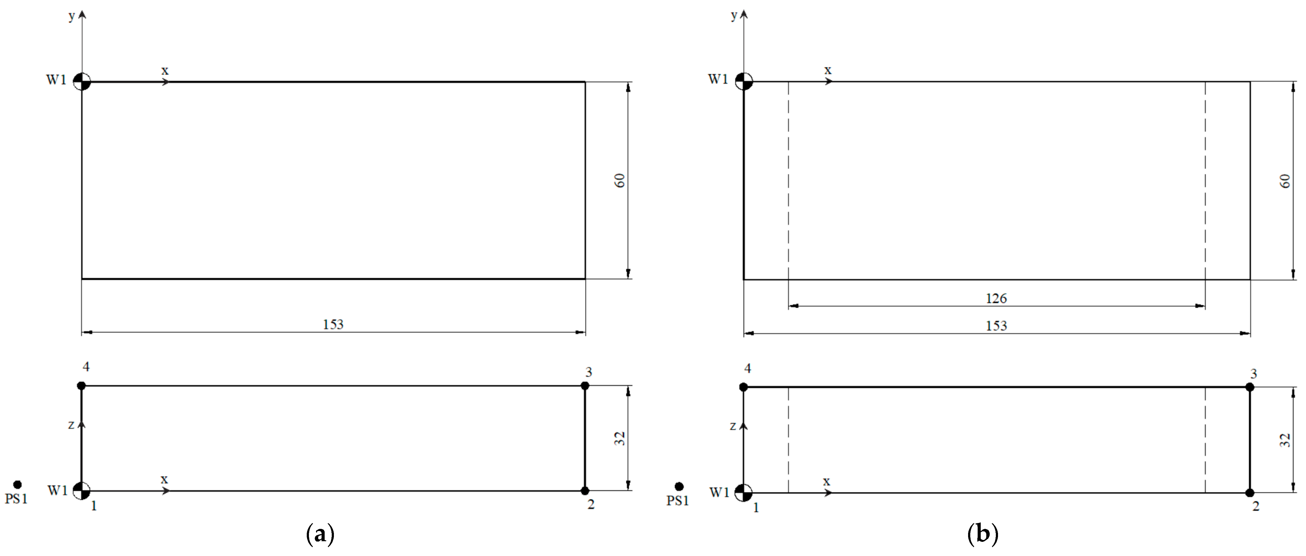
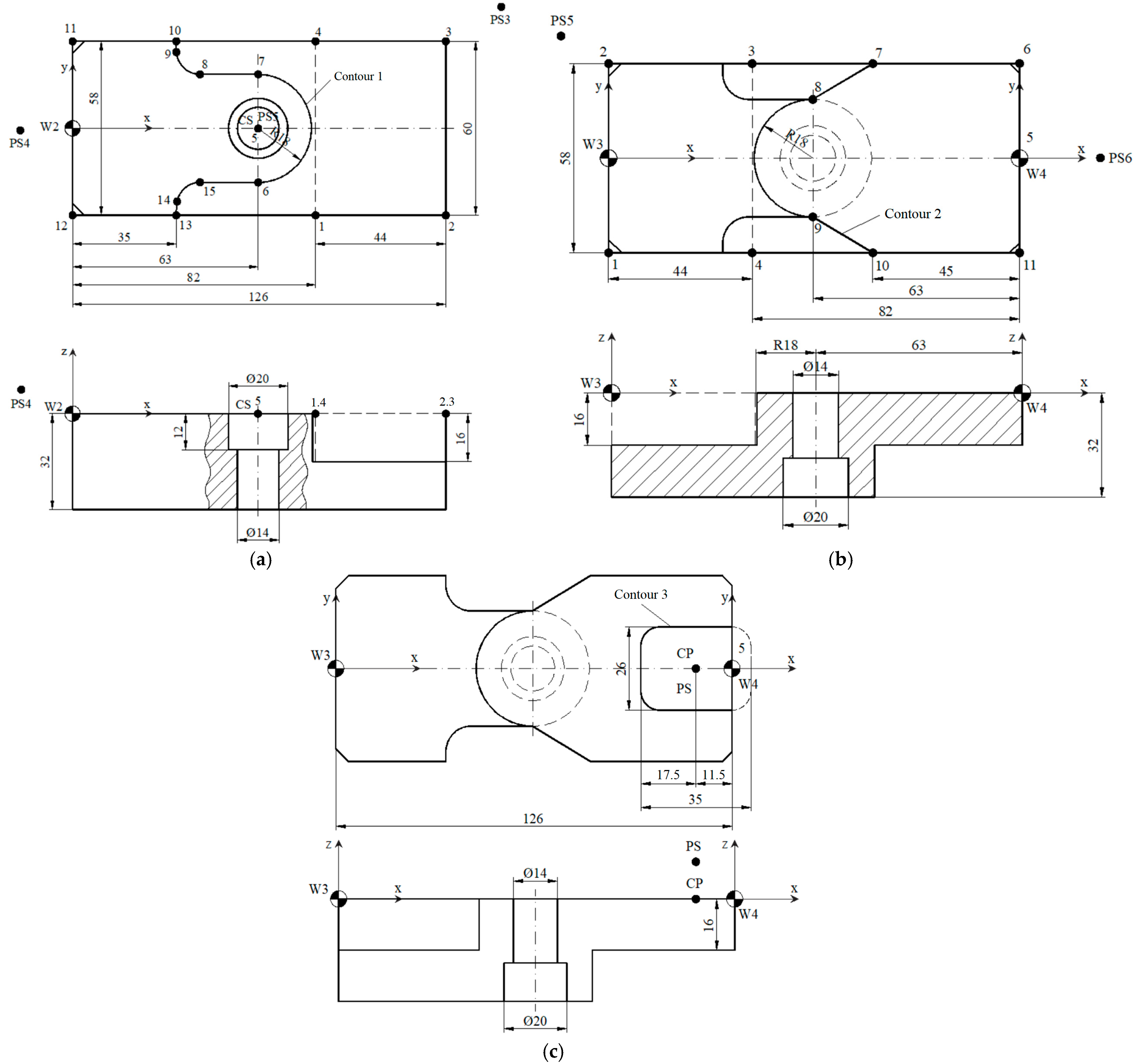
The part ”Double fixing fork” was created using the EMCO CONCEPT MILL 55 CNC system [20,25,26]. The CNC technological sketches are presented in Figure 4, Figure 5 and Figure 6 and the coordinates of the characteristic points (CPs) are in Table 5, Table 6, Table 7, Table 8, Table 9, Table 10 and Table 11.
The program blocks and technological phases are presented in Table 12.

3. Results

Several sequences from the main programs for obtaining the ”Double fixing fork” part, using the Siemens SINUMERIK 840D program [21,22], as well as the subprograms, are presented in Table 13 and Table 14.
Figure 7 shows the part ”Double fixing fork”, obtained using the EMCO CONCEPT MILL 55/TURN 55 CNC system.
This paper is not limited to an academic approach for purely didactic purposes, but proposes an applied research in the field of industry, with a potential for technological transfer in industrial production processes. Although the activities were carried out in an educational environment, the developed methodology faithfully reproduces the essential stages of an industrial CNC machining process, respecting the principles of design, simulation, programming, selection of working regimes, choice of technical materials and actual manufacturing of a functional part.
The analyzed part is a real component used in mechanical assemblies. Its design, the choice of material (PEHD 1000—a technical polymer frequently used in industrial applications) and the applied machining strategy were carried out according to industrial technological standards. The program used (Siemens SINUMERIK 840D), as well as the structure of the generated CNC program, are in line with modern factory practices, which proves that the process can also be implemented in real production contexts. This paper fits within the area of applied scientific research because it is not limited to a simple demonstration of educational skills, but offers a fully documented and experimentally validated solution for the manufacture of a real part, with applicability in prototyping, small series production and industrial training. In addition, the proposed flow can be transferred within a small- and medium-sized enterprise (SME) or production workshop to be tested under concrete working conditions, which would allow its integration into a functional technological system.
In terms of Technology Readiness Level (TRL), the paper can be classified as TRL 3, as it has been experimentally validated in a controlled laboratory environment, using real equipment and respecting industrial technological constraints, as seen in Figure 8. This can progress to TRL 4, as it is necessary to validate the method in a relevant industrial environment by testing the part under production conditions and evaluating the performances obtained in terms of quality, productivity and reliability. The paper provides the concrete foundations for this step and the methodology can be scaled and replicated for industrial purposes without major modifications.
Therefore, the paper is scientific in nature and aligns with modern directions in the field of applied engineering, contributing both to the practical training of future specialists and to the development of reproducible solutions for digitally assisted manufacturing. The potential for transfer to industry is real and well supported by the methodological structure and experimentally obtained data.

4. Discussion

Numerical control (NC) machine tools allow complex machining processes to be carried out with minimal human intervention, thus increasing the efficiency and productivity of a company. Their continuous modernization has led to the emergence and evolution of compact and intelligent systems, integrated with online diagnostic functions and automatic corrections. Future engineers also need a broad understanding of information technology and, above all, of the interrelationships between current technologies. For this reason, it is necessary to implement modules that facilitate the acquisition by future experts of the basic interdisciplinary skills addressed and thus prepare them for future professional challenges. The integration of CNC equipment into teaching activities allows not only a theoretical understanding of manufacturing processes, but also the development of skills related to programming, the choice of machining modes and the interpretation of technological parameters.
The paper contributes to the field of technical education, by implementing a didactic model that emphasizes learning through practice and solving real problems. The modular structure of the proposed technology, the adaptation of the processing sequences to the complexity of the part and the final evaluation of the quality of the part constitute an example of good practice for laboratory activity. This methodology can be easily replicated in other university centers, providing a clear framework for training in the field of CNC, including in the context of limited technical resources.
Based on the results obtained, directions for expanding the research can be outlined. The study can be continued by evaluating the behavior of other polymeric or composite materials in CNC processing, by developing advanced digital simulation modules (example: digital twin) or by integrating modern technologies such as augmented reality for operator guidance. Also, program optimization through evolutionary algorithms, testing different tools and applying automatic quality control methods can transform a didactic exercise into an applied research base.

5. Conclusions

The paper presented the manufacturing technology of the ”Double fixing fork” part using the EMCO CONCEPT MILL 55/TURN 55 CNC system. The use of the CNC system in the manufacturing of this part brought multiple advantages over traditional machining, such as the following: reduced execution times, high adaptability, but also the possibility of achieving complex geometries in a relatively short time.
The programming of the part allowed for more precise control of the cutting tool trajectory and machining parameters. EMCO numerical controlled machines have an intuitive interface, with the possibility of testing various machining scenarios. The process was scalable and precise, providing a solid technical basis for the training of future engineers in the numerical controlled machine sector.
The paper proved to be an effective framework for learning through practice, offering students the opportunity to go through a complete manufacturing process—from the design of the part to its physical realization in the laboratory, thus contributing to a solid and industry-oriented technological training. The ”Double fixing fork” part proved suitable for an educational study, both due to its complex geometric shape and the functional requirements it implies. This part allowed the application of a wide range of CNC operations (face milling, contour milling, drilling, counterboring, threading).
The use of high-density polyethylene (PEHD 1000) required the adjustment of technological parameters in order to avoid common defects associated with the processing of plastic materials, such as local melting, burr formation or loss of tolerances. It was thus demonstrated that a correct understanding of the material properties (strength, hardness, coefficient of thermal expansion) is important for the correct choice of tools, cutting speeds and feeds. EMCO Mill 55 CNC equipment, together with the SINUMERIK 840D control system, provided the ideal framework for carrying out a modern and efficient didactic activity. The intuitive interface, simulation capability and compatibility with the ISO standard language allowed the creation of precise and reproducible machining sequences. At the same time, it is possible to intervene in a controlled manner on the programs, observe the impact of changes on the tool path and evaluate the quality of the results obtained.
In relation to the current literature, the paper confirms the importance of integrating CNC machining methods in the industrial field, reinforcing the need to correlate theoretical training with practical experience in a context where digital and interdisciplinary skills are becoming important in modern production. Unlike other approaches focused exclusively on virtual simulations or simplified theoretical processing, this paper validates a complete manufacturing process—from 3D modeling to the physical realization of the part. Thus, the gap between academic learning and real industry requirements is reduced.
The equipment used, EMCO MILL 55, is a three-axis CNC machining center, which allows the execution of small-sized parts (maximum 180 mm × 120 mm × 70 mm). This limitation requires working with small-sized parts and excludes complex machining requiring five axes or advanced interpolations. Also, the technical characteristics of the machine—such as the maximum speed of the main spindle, engine power and rigidity—impose constraints on the regime parameters. In the case of polymeric materials, such as PEHD 1000, it was necessary to adjust the cutting speeds and feeds to avoid defects such as local melting, the appearance of burrs or the loss of tolerances, a task achieved through tests that allowed the selection of optimal parameters of the processing regime (Table 4 and Equations (1)–(8)). These adjustments, although adequate for didactic purposes, may limit the immediate applicability of the method in industrial processes of high productivity or high precision. Despite these constraints, the proposed methodology provides a solid, reproducible and scalable technological foundation, which can be extended to industrial environments by using higher-capacity CNC equipment.

Author Contributions

Conceptualization, N.B. and G.-A.M.; methodology, F.S. and V.P.; software, F.-I.M.; validation, N.B., V.-G.T. and V.P.; formal analysis, G.-A.M.; investigation, F.-I.M.; resources, F.S.; data curation, F.S. and V.-G.T.; writing—original draft preparation, G.-A.M. and F.-I.M.; writing—review and editing, N.B. and V.P.; visualization, V.-G.T. and V.P.; supervision, V.-G.T.; project administration, F.S.; funding acquisition, N.B. All authors have read and agreed to the published version of the manuscript.

Funding

This research received no external funding.

Data Availability Statement

Data are contained within the article.

Acknowledgments

The authors thank Engineer Tăbăcaru Valentin for his support and guidance in development of the CNC program for the part.

Conflicts of Interest

The authors declare no conflicts of interest.

References

  1. Sandor, R.N.; Pop, A.B.; Titu, A.M. Design and validation of a fixture device for machining surfaces with barrel end-mill on a 3-axis CNC milling machine. Appl. Sci. 2025, 15, 7379. [Google Scholar]
  2. Yan, X. Research and application of CNC machining method based on CAD/CAM/robot integration. Adv. Multimed. 2022, 2022, 5397369. [Google Scholar] [CrossRef]
  3. Gołebski, R. Parametric programming of CNC machine tools. MATEC Web Conf. 2017, 94, 07004. [Google Scholar] [CrossRef]
  4. Bhattacharyya, B.; Doloi, B. Modern Machining Technology. Advanced, Hybrid, Micro Machining and Super Finishing Technology; Academic Press: Cambridge, MA, USA, 2019; pp. 1–780. ISBN 978-012-812-894-7. [Google Scholar]
  5. Nguyen, D.K.; Huang, H.C.; Feng, T.C. Prediction of thermal deformation and real-time error compensation of a CNC milling machine in cutting processes. Machines 2023, 11, 248. [Google Scholar] [CrossRef]
  6. José, M.I.K.; Óscar, H.U.; Leonor, A.C.R.; Ramón, A.L.M. Extended reality applications for CNC machine training: A systematic review. Multimodal Technol. Interac. 2024, 8, 80. [Google Scholar]
  7. Baroiu, N.; Moroșanu, G.A.; Teodor, V.G.; Nedelcu, D.; Tăbăcaru, V. Prediction of surface roughness in drilling of polymers using a geometrical model and artificial neural networks. Mat. Plast. 2020, 57, 160–173. [Google Scholar] [CrossRef]
  8. Roman, O.; Trae, S.; Santiago, G.; Stanton, M.; Clumpner, B.; Hoyer, B.; Nowicki, M. Computer numerical control integration into the undergraduate mechanical engineering curriculum. In Proceedings of the ASME 2024 International Mechanical Engineering Congress and Exposition—IMECE2024, Portland, OR, USA, 17–21 November 2024. [Google Scholar]
  9. Petru, C.D.; Morariu, F.; Breaz, R.E.; Crenganis, M.; Racz, S.G.; Gîrjob, C.E.; Bârsan, A.; Biris, C.M. Development of a small CNC machining center for physical implementation and a digital twin. Appl. Sci. 2025, 15, 5549. [Google Scholar] [CrossRef]
  10. Baroiu, N.; Novac, G.; Tăbăcaru, V.; Moroșanu, G.A. The development cycle of machining operations on an educational CNC machine. Int. J. Ed. Inf. Technol. 2024, 18, 44–54. [Google Scholar] [CrossRef]
  11. Zahid, M.N.O.; Case, K.; Watts, D. End mill tools integration in CNC machining for rapid manufacturing processes: Simulation studies. Prod. Manuf. Res. 2015, 3, 274–288. [Google Scholar]
  12. Vishaldeep, S.; Hitesh, A.; Prashant, K.P.; Rahul, W. A methodology for simulation and verification of tool path data for 3-AXIS and 5-AXIS CNC machining. Int. J. Mech. Eng. Techn. (IJME) 2018, 9, 450–461. [Google Scholar]
  13. Mishra, S.; Mondal, G.; Kumarasamy, M. Development of low-cost CNC-milled PMMA microfluidic chips as a prototype for organ-on-a-chip and neurospheroid applications. Organoids 2025, 4, 13. [Google Scholar] [CrossRef]
  14. Carta, M.; Loi, G.; Mehtedi, M.; Buonadonna, P.; Aymerich, F. Improving surface roughness of FDM-printed parts throughCNC machining: A brief review. J. Comp. Sc. 2025, 9, 296. [Google Scholar] [CrossRef]
  15. Fountas, N.; Manolakos, D.; Vaxevanidis, N. Machinability assessment and multi-objective optimization of graphene nanoplatelets-reinforced aluminum matrix composite in dry CNC turning. Metals 2025, 15, 584. [Google Scholar] [CrossRef]
  16. Szadkowska, K.; Kepczak, N.; Stachurski, W.; Pawłowski, W.; Rosik, R.; Bechcinski, G.; Sikora, M.; Witkowski, B.; Sikorski, J. Influence of machining parameters on the surface roughness and tool wear during slot milling of a polyurethane block. Materials 2025, 18, 193. [Google Scholar] [CrossRef] [PubMed]
  17. Shuling, Z.; Jie, B. Research on CNC programming and machining process based on CAD/CAM technology. App. Math. Non. Sci. 2024, 9, 1–18. [Google Scholar]
  18. Martins, A.; Joao, L.; Costelha, H.; Neves, C. CNC machines integration in smart factories using OPC UA. J. Ind. Inf. Integr. 2023, 34, 100482. [Google Scholar] [CrossRef]
  19. Hongyi, W.; Xuanyi, W.; Xiaolei, D.; Hongyao, S.; Xinhua, Y. Review on design research in CNC machine tools based on energy consumption. Sustainability 2024, 16, 847. [Google Scholar]
  20. EMCO. Available online: https://www.emco-world.com/en/ (accessed on 15 June 2025).
  21. Siemens. Available online: https://cache.industry.siemens.com/dl/files/513/109481513/att_906053/v1/BHDsl_1015_ro-RO.pdf (accessed on 15 June 2025).
  22. Siemens. Available online: https://www.siemens.com/global/en/products.html (accessed on 16 June 2025).
  23. ICMIndustrie. Available online: https://www.icmindustrie.com/wp-content/uploads/2022/03/PEHD-1000-EN.pdf (accessed on 11 June 2025).
  24. Susac, F.; Tăbăcaru, V. Proiectarea dispozitivelor de prelucrare în construcţia de maşini. Bazele proiectării dispozitivelor de prelucrare. In Suport De Curs (Design of Machining Devices in Mechanical Engineering. Fundamentals of Machining Device Design. Course Material); Galati University Press: Galati, Romania, 2018; ISBN 978-606-696-127-1. [Google Scholar]
  25. Bučányová, M.; Riečičiarová, E. Specification of the component base for CNC processing centre EMCO Concept MILL 105. Appl. Mech. Mat. 2014, 693, 9–15. [Google Scholar]
  26. Wang, P.L.; Tsai, Y.T. Numerical analysis of CNC milling chatter using embedded miniature MEMS microphone array system. Inventions 2018, 3, 5. [Google Scholar] [CrossRef]
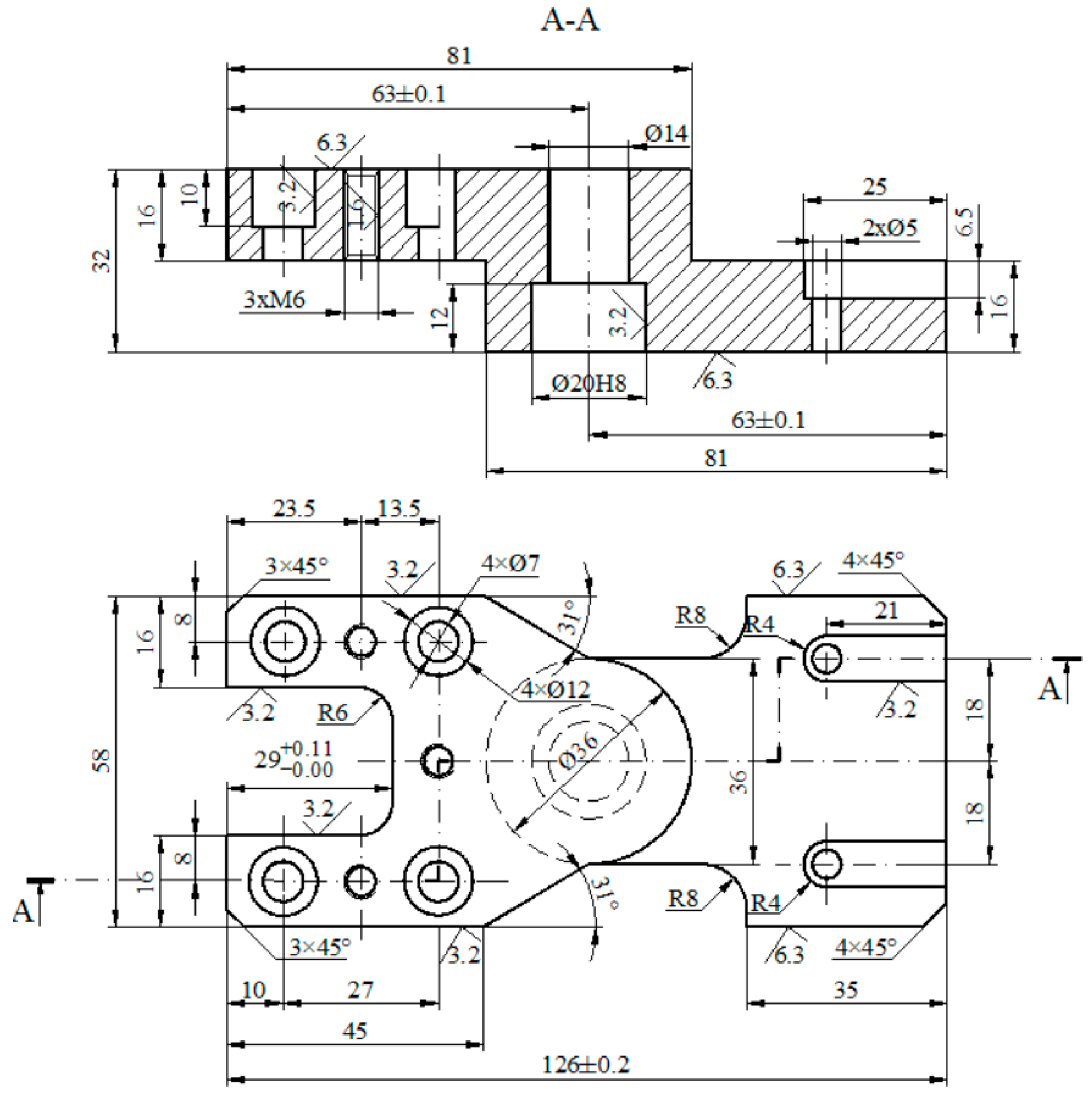
Figure 1. EMCO MILL 55 CNC: (a) CNC machine; (b) tool holder; (c) tool changer [1,10].
Inventions 10 00063 g001
Figure 2. Execution drawing of the ”Double fixing fork”.
Inventions 10 00063 g002
Figure 3. Numbering of the surfaces of the part “Double fixing fork”.
Inventions 10 00063 g003
Figure 4. CNC sketches at (a) side face milling, (b) face milling.
Inventions 10 00063 g004
Figure 5. CNC sketches at (a) contour milling 1, (b) contour milling 2, (c) contour milling 3.
Inventions 10 00063 g005
Figure 6. CNC sketches at (a) drilling, (b) channel milling and drilling.
Inventions 10 00063 g006
Figure 7. ”Double fixing fork” part.
Inventions 10 00063 g007
Figure 8. Technology Readiness Levels of the paper.
Inventions 10 00063 g008
Table 1. Types of surfaces.
Crt. no.Surface TypeCodeDimensions [mm]Tolerances,
TD [mm]
Roughness,
Ra [μm]
1.Horizontal
plane surface
SPO—01, 0263 × 16-6.3
2.Vertical
plane surface
SPV—03, 0445 × 16-3.2
3.Vertical
plane surface
SPV—05, 063 × 45°--
4.Vertical
plane surface
SPV—07, 0816 × 16--
5.Inclined
plane surface
SPΗ09, 1021 × 16--
6.Vertical connected plane surfaceSPRV—1129 × 26 × 16/R6+0.11
0
3.2
7.External cylindrical surfaceSCE—12Ø36 × 16--
8.Inner cylindrical surfaceSCI—13Ø14 × 20--
9.Inner helical cylindrical surfaceSCEI—14, 15, 163 × M6--
10.Inner cylindrical surfaceSCI—17, 18, 19, 20Ø11 × 10--
11.Inner cylindrical surfaceSCI—21, 22, 23, 24Ø7 × 6--
12.Horizontal plane surfaceSPO—25, 2663 × 16-6.3
13.Vertical plane surfaceSPV—27, 284 × 45°-6.3
14.Vertical plane surfaceSPV—2958 × 16--
15.Vertical plane surfaceSPV—30, 3135 × 16-3.2
16.Inner cylindrical surfaceSCI—32, 33Ø5 × 9.5--
17.Horizontal plane surfaceSPO—34, 3525 × 6.5--
18.Inner cylindrical surfaceSCI—36Ø20 × 12H83.2
19.Connected profiled surfaceSPR—3728 × 16/R8/R18--
Table 2. Processing methods.
PhaseProcessing MethodWorkstationTool TypeTool—Geometric Parameters [mm]
DRLtLs
1.1Face millingT7Cylindrical end mill1472070.98
1.2Face millingT2Cylindrical end mill1054596.12
2.1Cylindrical face millingT7Cylindrical end mill1472070.98
2.2Contour milling 1
CYCLE 72
T7Cylindrical end mill1472070.98
2.3Center drilling
CYCLE 81
T8Center drill3-966.55
2.4DrillingT7Helical drill10-3884.83
2.5.aCounterboring
POCKET 2
T2Cylindrical end mill1054596.12
2.5.bCounterboring
POCKET 2
T2Cylindrical end mill1054596.12
3.1Cylindrical face millingT7Cylindrical end mill1472070.98
3.2Contour milling 2
CYCLE 72
T7Cylindrical end mill1472070.98
3.3Contour milling 3
POCKET 1
T6Cylindrical end mill10522-
4.1Center drilling
CYCLE 81
T8Center drill3-966.55
4.2Drilling
CYCLE 81
T3Helical drill5-48-
4.3Drilling
CYCLE 81
T2Helical drill7-31-
4.4Counterboring
CYCLE 89
T4Counterbore12-26-
4.5Threading
CYCLE 840
-Metric tapM6-4085.30
5.1Channel millingT5Channel mill841390.15
5.2Center drillingT8Center drill3-966.55
5.3DrillingT3Helical drill5-48-
2.5.a and 2.5.b are the phases corresponding to the processing of surfaces 13 and 36; the D is the diameter of the cutting tool; R is the radius of the cutting tool; Lt is the length of the cutting tool edge; Ls is the length of the cutting tool.
Table 3. Mechanical properties of PEHD 1000 [23].
Yield Strength,
σc [MPa]
Tensile Strength,
σr [MPa]
Elongation at Break,
ε [%]
Hardness
HB
Elasticity Modulus,
E [MPa]
1915>5036750
Table 4. Geometric parameters.
PhaseTool TypeNumber of Teeth (z)Basic ParametersProgrammable
Parameters
t
[mm]
Sd
[mm/rot]
Sb
[mm/rot]
V
[m/min]
S
[rot/min]
F
[mm/min]
1.1Cylindrical end mill413 (32)0.06-25568.69136,48
1.2Cylindrical end mill413 (32)0.15-25796.17477,70
2.1Cylindrical end mill45 (16)0.15-25568.69314.21
2.2Cylindrical end mill44 (16)0.15-25568.69314.21
2.3Center drill-2.5-0.30252653.92769.17
2.4Helical drill-5-0.1524764.33114.65
2.5.aCylindrical end mill44 (12)0.05-25796.17159.23
2.5.bCylindrical end mill42.5 (32)0.05-25796.17159.23
3.1Cylindrical end mill45 (16)0.15-25568.69314.21
3.2Cylindrical end mill44 (16)0.10-25568.69227.47
3.3Cylindrical end mill44 (16)0.10-25568.69227.47
4.1Center drill-2.5-0.3252653.92769.17
4.2Helical drill-3.5-0.125.281610.2161.02
4.3Helical drill-3.5-0.1223.071049.59125.95
4.4Counterbore-6-0.1624.39647.29103.56
4.5Metric tap- -0.754.48238.29178.72
5.1Channel mill23 (6.5)0.013-25995.2225.87
5.2Center drill-2.5-0.30252653.92769.17
5.3Helical drill-2.5-0.1025.281610.2161.02
t represents the cutting depth, in [mm]; Sd —milling feed (on one tooth of the tool), in [mm/rot]; Sb —drilling feed, in [mm/rot]; V—cutting speed, in [m/min]; S—tool speed, in [rot/min]; F—feed rate, in [mm/min].
Table 5. Coordinates of characteristic points at side face milling and face milling—Figure 4.
W1Side Face MillingPS1
1234
X01531530−10
Y0032320
Z−0.5−0.5−0.5−0.55
W1Face millingPS2.1PS2.2
5678
X13413400−10163
Y060060−1070
Z−1−1−1−155
Table 6. Coordinates of characteristic points at face milling, drilling and counterboring.
W2Cylindrical Face MillingDrilling—CounterboringPS3PS4PS5CS
12345----
X821261268263136−106363
Y−29−292929040000
Z−16−16−16−16−5—center drilling
−35—drilling Ø10 (32 + 3)
−33—counterboring Ø14
−12—counterboring Ø20
51020-
Table 7. Coordinates of characteristic points at contour milling 1—Figure 5a.
W2Contour Milling 1
6789101112131415
X636343353500353543
Y−181818262929−29−29−26−18
Z−16−16−16−16−16−16−16−16−16−16
Table 8. Coordinates of characteristic points at cylindrical face milling.
W3Cylindrical Face MillingPS5
1234
X004444−10
Y−3030−303040
Z−15.8−15.8−15.8−15.85
Table 9. Coordinates of characteristic points at contour milling 2—Figure 5b.
W4Contour Milling 2PS6
567891011
X00−45−63−63−45010
Y0292918−18−29−290
Z−15.8−15.8
CHF=3
−15.8−15.8−15.8
CR=18
−15.8−15.8
CHF=3
5
Table 10. Coordinates of characteristic points at contour milling 3—Figure 5c.
W4Contour Milling 3
PSCP
X−11.5−11.5
Y00
Z−18−18
Table 11. Coordinates of characteristic points at drilling and channel milling—Figure 6.
W4Drilling
PS7G1G2G3G4G5G6G7
X0−23.5−37−23.5−10−37−10−37
Y0210−212121−21−21
Z20−18.5−18.5−18.5−19/−10−19/−10−19/−10−19/−10
W5Channel milling. Drilling
PS8CP1CP2G8G9
X0−6−62121
Y018−1818−18
Z20--−8
−18.5
−8
−18.5
Table 12. Program blocks and technological phases.
Program Block—BPToolWorkstationTechnological Phases
PROGRAM 1
BP1Cylindrical end millD = 14
T7
(a) Face milling, Phase 1.1
BP2Cylindrical end millD = 10
T2
(a) Face milling, Phase 1.2
PROGRAM 2
BP3Cylindrical end millD = 14
T7
(a) Cylindrical face milling, Phase 2.1
(b) Contour milling 1, Phase 2.2
BP4Center drillD = 3
T8
(a) Center drilling, Phase 2.3
BP5Helical drillD = 10
T7
(a) Drilling, Phase 2.4
BP6Cylindrical end millD = 10
T2
(a) Counterboring, Phase 2.5.a
BP7Cylindrical end millD = 10
T2
(a) Counterboring, Phase 2.5.b
PROGRAM 3
BP8Cylindrical end millD = 14
T7
(a) Cylindrical face milling, Phase 3.1
(b) Contour milling 2, Phase 3.2
BP9Cylindrical end millD = 10
T6
(a) Contour milling 3, Phase 3.3
PROGRAM 4
BP10Center drillD = 3
T8
(a) Center drilling, Phase 4.1
BP11Helical drillD = 5
T3
(a) Drilling, Phase 4.2
BP12Helical drillD = 7
T2
(a) Drilling, Phase 4.3
BP13CounterboreD = 12
T4
(a) Counterboring, Phase 4.4
BP14Metric tapD = M6
T
(a) Threading, Phase 4.5
PROGRAM 5
BP15Channel millD = 8
T5
(a) Channel milling, Phase 5.1
BP16Center drillD = 3
T8
(a) Center drilling, Phase 5.2
BP17Helical drillD = 5
T3
(a) Drilling, Phase 5.3
Table 13. The main programs.
Program BlockTechnological PhaseProgram Structure (Technological Lines)
BP1Face milling
Phase 1.1
G54
TRANS X-25 Y-32 Z40.5
T7 D1 M6
S568.69 M3
G0 Z-12 Y0 Z5
G1 X-10 Y0 Z0.5 F136.48
G1 X0 Y0
G1 X153 Y0
G1 X153 Y13
G1 X0 Y14
G1 X0 Y26
G1 X153 Y26
G1 X153 Y32
G1 X0 Y32
G0 X-10 Y0 Z5
G0 Z100
………………
BP4Center drilling
Phase 2.3
T8 D1 M6
S2653.92 M3 F769.17
G0 X63 Y0 Z20
CYCLE81 (5, 0, 3, −7.5, 0)
………………
BP13Counterboring
Phase 4.4
T4 D1 M6
S647.29 M3 F103.56
G0 X0 Y0 Z20
MCALL CYCLE89 (5, 0, 3, −10, 0, 3)
CYCLE801 (−37, −21, 0, 27, 42, 2, 2)
MCALL
Z100
BP14Threading
Phase 4.5
T5 D1 M6
S238.29 M3 F178.72
G0 X0 Y0 Z20
MCALL CYCLE840 (5, 0, 3, −18.5, 0, 04, 3, 0, 0.75, 0, 3, 0, 0)
CYCLE801 (−37, −21, 0, 27, 42, 2, 2)
MCALL
Z100
………………
BP17Drilling
Phase 5.3
T3 D1 M6
S1610.2 M3 F161.02
G0 X0 Y0 Z20
CYCLE81 (5, 0, 3, −18.5, 0)
G0 Y18
CYCLE81 (5, 0, 3, −18.5, 0)
Z100
M30
Table 14. Subprograms.
MOG C1MOG C2
G1 X0 Y0
G1 X0 Y29 CHF=4
G1 X35 Y29
G1 X35 Y26
G3 X43 Y18 CR=8
G1 X63 Y18
G2 X63 Y-18 CR=18
G1 X43 Y-18
G3 X35 Y-26 CR=8
G1 X35 Y-29
G1 X0 Y-29 CHF=4
G1 X0 Y0
M17
G1 X0 Y0
G1 X0 Y29 CHF=3
G1 X-45 Y29
G1 X-63 Y18
G3 X-63 Y-18 CR=18
G1 X-45 Y-29
G1 X0 Y-29 CHF=3
G1 X0 Y0
M17
Disclaimer/Publisher’s Note: The statements, opinions and data contained in all publications are solely those of the individual author(s) and contributor(s) and not of MDPI and/or the editor(s). MDPI and/or the editor(s) disclaim responsibility for any injury to people or property resulting from any ideas, methods, instructions or products referred to in the content.