1. Introduction
A trolley is an object with wheels for moving or transporting items from one location to another. The device is a useful mechanism in factories, shops, supermarkets, homes, office complexes [
1], warehouses, and marketplaces [
2], and its primary aim is carrying items that are difficult to carry due to their weight [
2]. When it comes to moving products higher or lower than ground level, there are situations in which a conventional trolley cannot be used, such as when there is uneven terrain or when one is going up to any level above ground level. This task is not simple, especially if there are no lifting facilities, such as elevators or conveyers [
3].
In the Regional Regulation Bandung, Indonesia, concerning the reliability requirements of buildings, it was stated that every building with a height above four floors must have an elevator [
4]. In developing countries like Pakistan, many buildings do not possess elevators and the primary mode of access between different floors is stairs [
5]. In Malaysia, for all non-residential buildings more than four stories above or below the main access level, at least one lift is required [
6]. This means that for buildings that have two to four floors, moving goods from the bottom to the top floor would be an issue. For example, several university dormitories located in Bandung have three levels or more with no escalators or elevators. Students come and go every year, forcing them to transport their goods to and from their dormitories via the stairs. If a suitable trolley is available, it would definitely make it easier for students to carry their items [
4].
Walking up and down stairs is among the most challenging and hazardous activities of daily living for older individuals. This is evidenced by the reports that stair falls account for more than 10% of fatal fall accidents. The circumstances of stairway falls often include engagement in risky behaviors, such as using stairs laden with objects, using the stairs while wearing socks, not using the handrail, and carrying items when walking up or down stairs [
3]. In a study conducted on the safety of older people on stairs, it was found that when needing to move an object up or down the stairs that may cause them a problem, 29% of 157 participants would not ask for help but ‘have a go anyway’ [
7].
In a report published by the Bureau of Labor Statistics, over 57% of injuries among laborers and freight, stock, and material movers were to the back and shoulders. Musculoskeletal disorders are injuries or illnesses that result from overexertion or repetitive motion [
8]. Bending, twisting, and turning are commonly cited movements that cause back injuries. Strains and sprains from lifting loads improperly or from carrying loads that are either too large or too heavy are common hazards associated with manually moving materials. When employees used smart lifting practices such as using hand trolleys and pushcarts, they are less likely to suffer from back sprains, muscle pulls, wrist injuries, elbow injuries, spinal injuries, or other injuries caused by lifting heavy objects [
9]. However, when moving objects between floors, in most cases, specialized mechanical lifting equipment needs to be used to reduce manual handling risks. Thus, the lack of elevators in many facilities, the risky behaviors among older individuals when carrying items on stairs, and the risk of injuries among workers carrying goods in warehouses have driven the need to develop a specialized trolley for stair climbing.
A stair-climbing trolley is a type of trolley that can be pushed, pulled up or down, and stand on a stairway. Stair-climbing trolleys can be manual or battery-powered and, when used properly, can protect people from back injuries and other health problems that can result from lifting heavy loads [
10].
A two-wheel (one on each side) trolley was designed by Chhabra et al. (2022) [
11] for staircase climbing. The trolley was designed such that its handle extends to an arm that holds a 60 cm diameter wheel. At the same time, the arm is also connected to the base that holds the load for the trolley. The design allows for the base to be lifted when the handle is pulled. When the loaded trolley comes near a step, the wheels stop rotating. By pulling the handle more, the base of the trolley is lifted, shifting the center of gravity towards the next stair step. This causes the wheel to rotate, leading to the trolley being lifted to the next stair step [
11]. However, there is no mention of foldability or space-saving features, which may be an issue in areas with limited space. Additionally, its large wheels may add weight to the product, which could burden users during its operation. Nevertheless, this staircase-climbing trolley could be useful for strong workers in large warehouses.
Hasan and Rashid (2019) [
12] designed an eight-wheel stair-climbing cart, with four wheels on each side. The four wheels were fastened to connecting sheets with nuts and bolts such that they could rotate about their axis to climb stairs. According to the authors, the unique feature of this design enables users to rest when the cart is placed on two stairs. This is especially important since, when pulling the load and cart upstairs, the tensile stress upon the hand increases a lot. This may result in pain as well as fatigue while carrying loads [
12]. Such design is useful for users who may need short breaks while climbing. However, assuming this design uses wheels of a similar size, integrating eight units of wheels instead of four or six definitely would increase the weight of the trolley, thus requiring a greater tensile stress. On top of that, despite the eight-wheel cart design having the added convenience of being able to pause, it may be inefficient and lead to fatigue as users need to exert extra tensile stress to restart the movement. Nevertheless, such design definitely appeals to a specific group of users who require pauses during the cart’s operation. For the rest, a motorized design may offer a less physically demanding alternative.
A six-wheel trolley, which is more commonly known as tri-wheel due to the three wheels used for each side of the product, is the preferred design for many researchers and engineers in the development of staircase-climbing trolleys [
13,
14,
15,
16,
17,
18,
19,
20,
21,
22,
23]. This is because tri-wheel trolleys work on the principle that when one wheel touches the step, the frame holding the three wheels starts to rotate, landing the next wheel on the next step. As the wheel rotates and touches the step, the frame rotates again, landing the next wheel onto the next step [
24]. This process sums up the climbing process of the tri-wheel trolley.
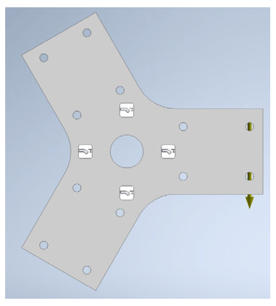
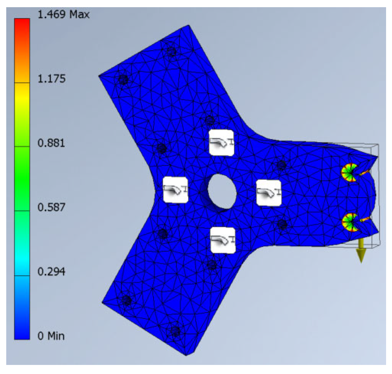
Muhammad and Wan Mohd (2023) [
25] designed a tri-wheel stair-climbing trolley following a thorough procedure which included a literature review of previous research, a finite element analysis (FEA) of the trolley structure, material selection, design sketches, a structural analysis using FEA, and a simulation of the motion of the trolley. The final design of the trolley, tested under a 40 kg load, was further improved with an adjustable height feature, which provides added value for various users [
25]. However, the absence of an extendable wheel frame may lead it to be unsuitable for different staircase profiles.
Olodu et al. (2022) [
26] designed and fabricated an electric-powered, tri-wheel, stair-climbing trolley that has the ability to climb a 45-degree stairwell while carrying a 50 kg load. The success of the trolley can be contributed to the meticulous design of the tri-wheel, which incorporates five crucial factors, of which two are the height and the width of the stairs. Additionally, when compared to a conventional hand trolley, the electrically powered stair-climbing trolley displayed an enhanced performance efficiency (87%). Nevertheless, the authors admitted that 45 degrees was the maximum gradient the trolley could climb [
26].
While the tri-wheel seems like an ideal design for stair-climbing trolleys, it is limited to a narrow range of stair heights due to its fixed frame size. Thus, users struggle to operate the trolley on stairs that are too short or tall relative to the wheel frame. In contrast, trolleys designed with an extendable frame can accommodate a wider range of stair heights, allowing for better adaptability across different stair profiles, as suggested by previously published works [
27,
28].
Ishak and Pailin (2023) [
29] designed and fabricated a prototype of a staircase-climbing trolley, which they coined a hand truck. Prior to its design, the authors first determined the essential needs of trolley users through observations and interviews with students staying in a seven-story hostel, specifically regarding the transportation of goods using a staircase. The students complained that, among other factors, the conventional trolley provided was inadequate to carry goods up the staircase due to its inflexible wheel structure. As a result, the students had to increase their efforts to lift the trolley for staircases with a larger width and height. Then, the authors sketched several concept designs, conducted concept screening, selected the final design, conducted a linear static FEA, and conducted usability testing. The final design consists of an adjustable frame, an adjustable handle length, and foldability, among other features. The usability testing results showed flexibility in extending the wheel frame by 2 cm, 4 cm, and 6 cm, which is advantageous for applications across different staircase sizes [
29].
A foldable stair-climbing trolley offers practical advantages by saving space and being easy to store. This design is particularly significant for users working in confined spaces or urban environments where space is limited. Shiau et al. (2015) [
30] utilized a mutual pivot junction with supporting frames and a handrail in their development of an innovative foldable trolley. The design not only allowed for changing the folding angle and folding method, but it also allowed it to be easily carried by pulling the handrail on roller wheels after folding it. Through a static analysis, it was found that the safety coefficient was always greater than 1.5; thus, the safety of the entire structure was only impacted to an extremely low extent [
30]. Aside from the work by Shiau et al. (2015), the design features of other foldable products, such as multifunctional stretchers, may offer valuable insights for improving portability and storage efficiency [
31].
Table 1 displays the summary of stair-climbing trolley designs and key features from the selected studies reviewed above, as well as other relevant works [
32,
33,
34,
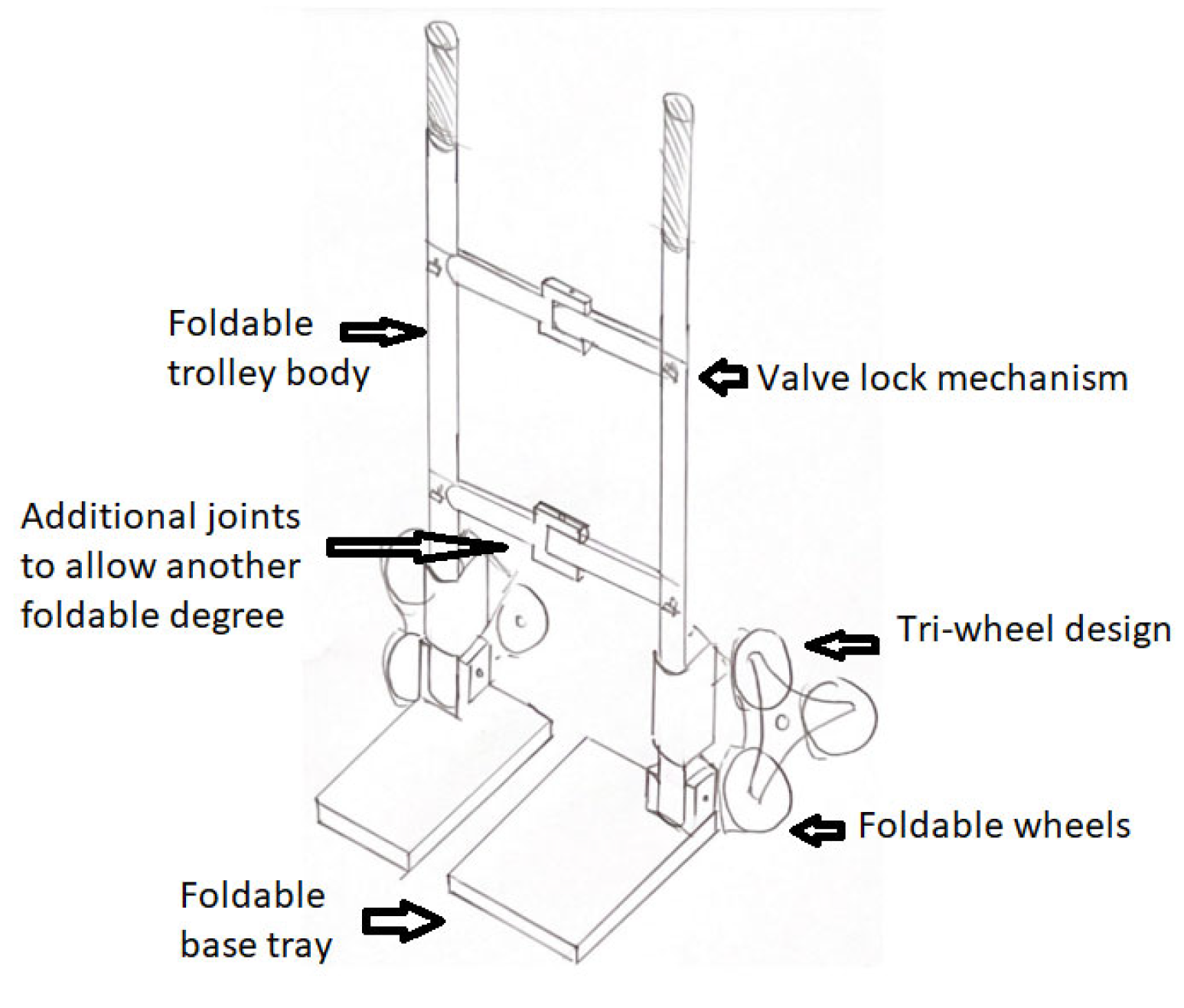
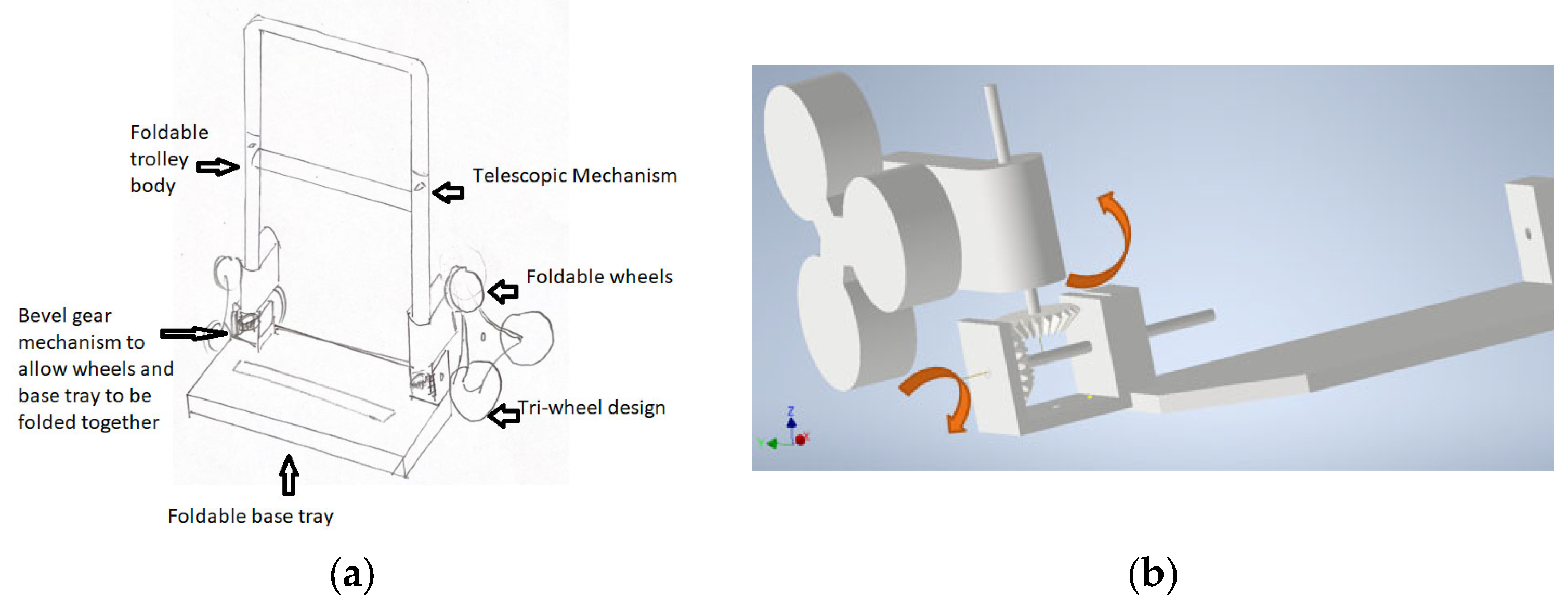
35]. To the best of the authors’ knowledge, there are no reports of a stair-climbing trolley that incorporates a tri-wheel with an extendable and foldable body frame to save space, adjustable tri-wheel radii, and a motorized design for reduced physical effort while transporting goods up and down staircases. Thus, this project aims to design, develop, and analyze a tri-wheel trolley with motorized, adjustable, and foldable features. The development of this trolley may help reduce physical strain when carrying heavy loads up staircases, especially for workers and residents. Additionally, this trolley may assist elderly people who live alone, giving them the ability to carry out tasks independently.


 ,
, 


