1. Introduction
The advancement of wireless communication technology, exemplified by the Global System for Mobile (GSM), has significantly revolutionized the manner in which individuals engage and exchange information. GSM, as a highly prevalent cellular communication standard, provides a robust and dependable means of transmitting data with enhanced security measures [
1]. Ensuring data security is crucial in such systems to safeguard sensitive user information against unauthorized access and interception. The A5/1 encryption technique, which is a fundamental component of GSM security, functions by partitioning a 64-bit session key (Kc) into three linear feedback shift registers (LFSRs). The Linear Feedback Shift Registers (LFSRs) are subsequently merged in accordance with predetermined algorithms in order to produce encrypted data [
2].
Nevertheless, despite the established and effective nature of the A5/1 encryption process, there exists a dearth of a complete probabilistic model that assesses the likelihood of compromising or intercepting the session key (Kc). The present study aims to fill a significant need in the literature by proposing an innovative probabilistic model for evaluating the security of encrypted data within the GSM environment. Effective communication plays a key role in our everyday existence. The ability to effectively communicate one’s message at any time and in any location is heavily dependent on the level of connection established with the recipient. During ancient times, individuals employed various methods, such as fire, smoke, and carrier pigeons, to transmit their messages. Over time, it has been recognized that the need for a rapid carrier is essential in order to minimize the time required for message delivery and reduce the loss of crucial information. The radio was created in the 1880s by Guglielmo Marconi [
3]. Compared to other methods, the radio is an invention that provides a noticeably faster mode of message transmission. The chosen medium’s intrinsic properties will determine whether data can be successfully sent from one place to another. In 1946, the mobile telephone service (MTS) was first created [
4]. Only one party could send a speech at any given time when the radio link was in simplex mode, which it was.
This method’s significant power requirement forced the use of sizeable batteries in the instruments, which was one of its limitations. The Advance Mobile Phone System (AMPS) was introduced to solve this restriction [
5]. The AMPS used analog frequency-based modulation and had 666 pairs of speech channels. Narrowband AMPS was developed in 1991 by making changes to the architecture of the Advanced Mobile Phone System (AMPS). The NAMPS is based on the use of time-division multiple access (TDMA), digital modulation, and voice compression techniques [
6,
7]. However, the introduction of the Mobile Communication System was prompted by the need for greater capacity. Digital Cellular Network is recognized as the initial system that enables a cellular user located in one European country to function seamlessly in another [
8]. GSM has seen rapid growth and has emerged as the most widely adopted communications system. The initial implementation of GSM was in the form of a second generation (2G) network, which was first established in Finland. The steady expansion of 2G was a result of technological advancements [
9].
Currently, there is a global deployment of 3G cellular systems. The International Telecommunication Union (ITU) established the 3G standards, known as Universal Mobile Telecommunication Systems (UMTS) [
10]. Subsequently, the communications industry’s most significant companies became affiliated with the 3rd Generation Partnership Project (3GPP) initiative. The primary objective of this program was to generate the technical requirements for a third generation (3G) telecommunications system. The 3GPP organization is the sole entity entrusted with the job of overseeing the 3G system. The allocation of the radio spectrum for UMTS is consistent between Europe and Japan, although it differs in the United States, where IMT-2000 is dedicated to 2G [
11]. The 3G concept demonstrated compatibility with IS-95B systems, enabling their coexistence within the same spectrum concurrently. Subsequently, these allocations were expanded. There exist numerous approaches to improve the infrastructure. Additional specifications for GSM have been transmitted by the 3rd Generation Partnership Project (3GPP) working groups.
With the continuous advancement of technologies [
12], it is imperative to enhance the encryption and decryption mechanisms to ensure heightened security for our data. Numerous encryption and decryption mechanisms have been developed and proven to be valuable in the context of wireless mobile communication systems. The A5/1 stream cipher is a modified cryptographic algorithm that is widely employed by GSM. The study proposed the implementation of two novel combinational designs with respective total bit lengths of 64 and 128 bits, which are subsequently realized in hardware [
13]. The use of area, efficiency, and power in hardware-level implementation is influenced by the substitution of the XOR function with a multiplexer. This leads to the conclusion that the user has provided a numerical sequence consisting of the numbers [
14,
15,
16]. In another study, the authors made alterations to two hardware-implemented designs and subsequently conducted a comparison of their power consumption with that of the usual design of the A5/1 stream cipher [
17]. The abbreviations used in this article are detailed in
Table 1.
The findings indicate that there is an inverse relationship between the rate of hardware power consumption and the number of tapping bits utilized in the design. The literature acknowledges that the influence of tapping bits on the security strength of a design, particularly in generating random binary sequences, is minimal. However, it is worth noting that tapping bits do have a positive effect on the performance of the hardware, as evidenced by several studies [
18,
19,
20,
21]. The administration of information security is a crucial matter that necessitates efficient handling. In order to protect privacy during the exchange of information, the original data is subjected to encryption. In the GSM (Global System for Mobile) standard, encryption is implemented subsequent to Authentication in order to safeguard the privacy of callers during voice transmission subsequent to signaling [
22]. The encryption process in GSM involves utilization of the A5 algorithm family and Linear Feedback Shift Registers (LFSRs). The cryptographic algorithm under consideration exhibits multiple vulnerabilities, hence compromising the assurance of privacy. This study proposes several strategies for enhancing the security of the generated bit stream employed in encryption. The literature has suggested a number of methods to improve the functionality of fingerprint recognition systems (FSRs). These techniques encompass the transformation of linear FSRs into non-linear FSRs, the integration of the user’s present geographical coordinates, and the utilization of pre-existing 32-bit SRES in the authentication process [
23,
24,
25,
26]. Moreover, in [
27] the authors proposed an end-to-end AES-based encryption approach for smartphones, while the authors in [
28] provided a comprehensive survey of encryption algorithms and network vulnerabilities. Additional efforts, including the use of AES-256 [
29], reverse engineering techniques [
30], and quantum-enhanced authentication protocols [
31], highlight the ongoing interest in securing mobile communication systems. For a more in-depth exploration of these techniques, the reader is referred to the detailed discussions in [
32,
33,
34,
35,
36]. Although the encryption mechanism of GSM is secure, no probabilistic model has yet been formulated to analyze the probability of breaking or the interception of Kc. Therefore, it is required to develop an expression to analyze and enhance the security of the encrypted data. This paper makes the following key contributions:
A novel probabilistic model is proposed to assess the vulnerability of GSM A5/1 encryption and it is tested in three encryption scenarios using 5, 7, and 9 LFSRs to evaluate performance and security implications.
A closed-form expression is developed to calculate the number of possible key combinations as the number of registers increases.
GSM encryption is enhanced by increasing the number of LFSRs (5, 7, and 9) without altering the 64-bit session key length.
A majority function-based perturbation is introduced to improve key complexity and resist attacks.
Simulations were performed to investigate the impact of increasing LFSRs on data interception risk.
Data security is improved for context-aware intelligent visual analytics in real-time environmental monitoring systems.
The rest of the paper is organized as follows: In
Section 2, various algorithms used to secure communication are discussed.
Section 3 reviews the related work, followed by a discussion of the materials and methods in
Section 4.
Section 5 presents the simulation results, while
Section 6 concludes the study and outlines future research directions.
Table 1.
Comparative summary of selected notable studies and their limitations.
Table 1.
Comparative summary of selected notable studies and their limitations.
| References | Techniques | Outcome | Limitations | Key Findings |
|---|
| [16] | Hardware implementation of modified A5/1 stream cipher | Improved hardware design for A5/1 modification | Lack of detailed dataset or specific performance metrics | Hardware implementation enhances A5/1 security |
| [18] | Modified A5/1 stream cipher for secured GSM communication | Enhanced A5/1 encryption mechanism for improved security | Limited discussion on potential vulnerabilities of the new algorithm | Modifications address A5/1 weaknesses |
| [21] | LFSR-based stream cipher (enhanced A5/1) | Introduction of enhanced A5/1 variant based on LFSRs | No detailed comparison with the original A5/1 security | LFSR-based variant improves A5/1 security |
| [25] | A5/1 stream cipher modified for secured GSM communication | Proposal of modified A5/1 algorithm for GSM security | Lack of comprehensive Evaluation against attacks | Modifications strengthen A5/1 against attacks |
| [27] | Cryptanalysis of alleged A5 stream cipher | Detailed analysis of A5 stream cipher vulnerabilities | Limited discussion on countermeasures or improvements | Reveals vulnerabilities and potential attacks on A5/1 |
| [30] | Improved guess-and-determine attack on A5/1 | Introduction of improved attack technique against A5/1 | Focus primarily on attacking rather than improving A5/1 | Highlights potential weaknesses in A5/1’s security |
| [32] | Enhancement in feedback polynomials of LFSR | Proposal of enhancements to A5/1’s LFSR feedback polynomials | Limited Evaluation of proposed enhancements’ effectiveness | Suggests modifications to improve A5/1’s cryptographic properties |
2. Security Mechanism of GSM
In the field of mobile communications, the transmission of data occurs between a mobile endpoint and either another mobile endpoint or a fixed endpoint. The information provided is of a personal and confidential nature. The transmission should be executed in a manner that significantly mitigates the likelihood of data breaches through hacking. In this context, it is imperative for GSM to function as a secure network in order to uphold the confidentiality of data transmission between the sender and the recipient. Due to the wireless nature of communication between the transmitter and receiver in GSM, an unauthorized individual can exploit the air interface in order to gain unauthorized access to the data of a valid user within the network. Therefore, it is imperative to implement measures to ensure the security of GSM networks by validating the legitimacy of its users. Many cryptographic algorithms are used to secure the data. GSM has a special way to secure data:
The three major algorithms used in GSM are A3, A5, and A8. These are introduced by the Security Algorithms Group of Experts (SAGE). The three algorithms mentioned earlier explained as follows:
- i.
A3 Algorithm This algorithm is used to authenticate the user by authenticating their SIM card in the GSM network.
- ii.
A5 Algorithm After authentication of the user, this algorithm is used to encrypt voice and data. This algorithm has four versions. A5/0 is a dummy cipher, and it is a weak algorithm; A5/1 is used in some parts of the world. The newest version is A5/3, which is based on the KGCORE function for 3GPP mobile communications [
37].
- iii.
A8 Algorithm This algorithm is used for generating symmetric encryption keys that are used in A5/1 or A5/2 [
38]. There are three main components related to GSM Security:
- (i)
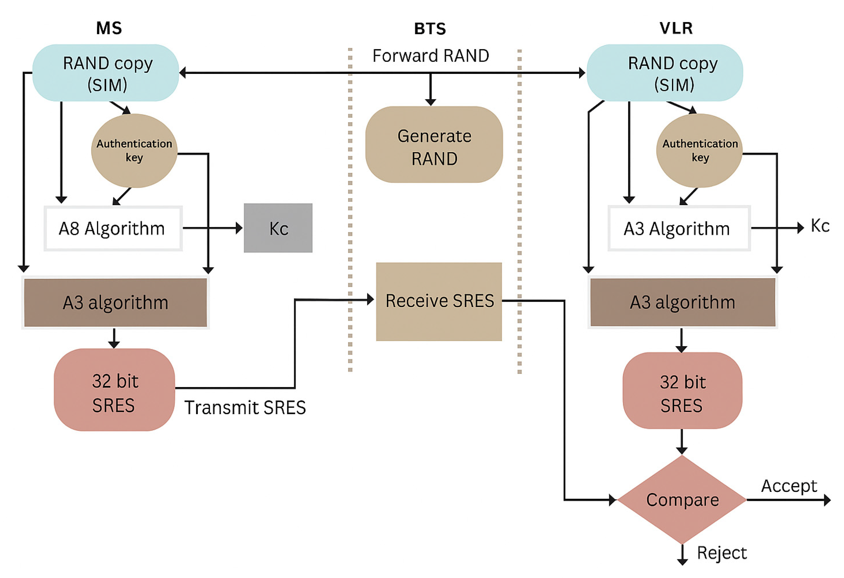
Base Transceiver Station (BTS) The main function is to generate a random number (RAND) of 128 bits and transfer it to the Mobile station. Its work also includes receiving the SRES and transmitting it to the VLR.
- (ii)
Mobile Station (MS) The MS uses A3 and A8 algorithms. Both algorithms use a 128-bit random number (RAND), and the authentication key (Ki) is stored in a SIM. The A8 algorithm produces a 64-bit session key, which is used in encryption, and the A3 algorithm is used to obtain SRES of 32 bits.
- (iii)
Visitor Location Register (VLR) The working of VLR is the same as MS; it contains A3 and A8 algorithms. It produces 32-bit SRES, and the received SRES form BTS produced by MS matches its own signed response with the received SRES if they are the same, so authentication is possible [
39,
40,
41]. This is shown in
Figure 1 below:
- (i)
Authentication Center
Authentication is the first and most important step in GSM security. The GSM authentication center is used to check the authenticity of every SIM card available to users. If authentication fails, then the user is blocked from using the network. On the other hand, when authentication is achieved, the user is allowed to communicate with the network. In the early 1990s, the initial security key of 64 bits seemed to be reasonable, but due to rapid improvements in computing power and successful attacks of brute forces (programs that decode keys or passwords) the length or size of the authentication key was made to be 128 bits. As is common knowledge, the most important aspect of the authentication procedure is the authentication key, which is denoted by the symbol Ki. Therefore, it cannot be transmitted over the air without any protection. It is recommended that it must be placed in a SIM card in MS. [
42].
- (ii)
Authentication Process
The A3 algorithm is used to authenticate the user; either it is legal to communicate with the network, or the user is blocked. The signed response (SRES) of 32-bit from MS is formed by using the steps so that the subscriber is allowed to communicate with the GSM network:
Firstly, the BTS generates a 128-bit random number and then transmits it to the mobile station.
Using the A3 algorithm, the cell phone encrypts a random number (RAND), and as a result, a 32-bit signed response is generated. This is shown in
Figure 2.
In parallel, the VLR can calculate SRES at the same time because it has a copy of the A3 algorithm.
The VLR matches the value of receiving SRES with its own calculated SRES value.
In the event that the two figures are comparable, the authentication will be approved, and the subscriber will be permitted to use the GSM [
43].
- A.
Encryption in GSM
The second important step in GSM security is encryption. For this purpose, the session key, denoted by Kc plays a vital role in securing the data. Both parties, i.e., the BTS and MS, must have similar Kc in order to encrypt or decrypt the data. The MS generates the session key (Kc) with the help of the A8 algorithm by taking its authentication key Ki, and the random number (RAND) sent by the BTS. Then, the process of encrypting the data through the session key is carried out using the A5 algorithm.
- B.
A5/1 Algorithm
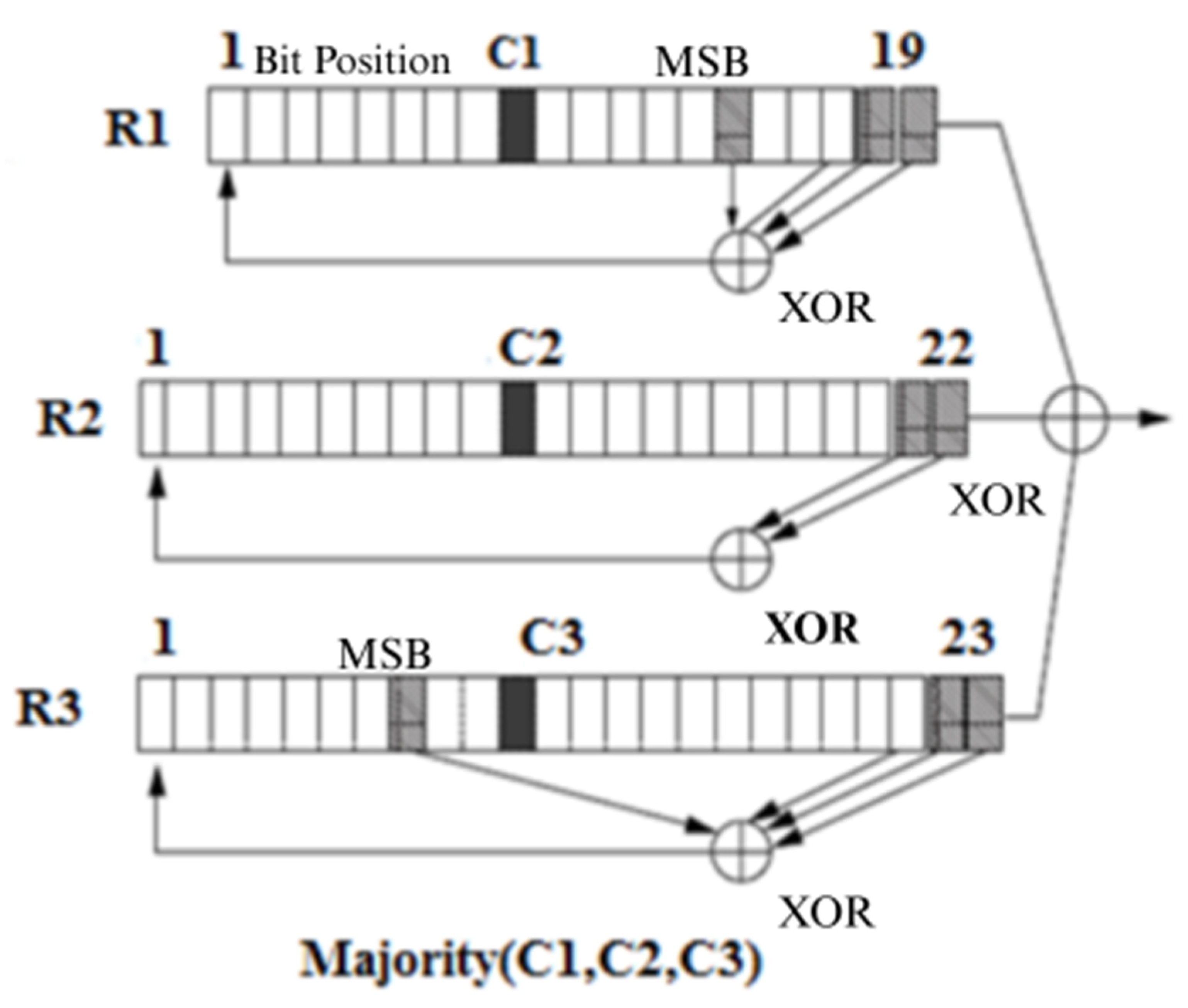
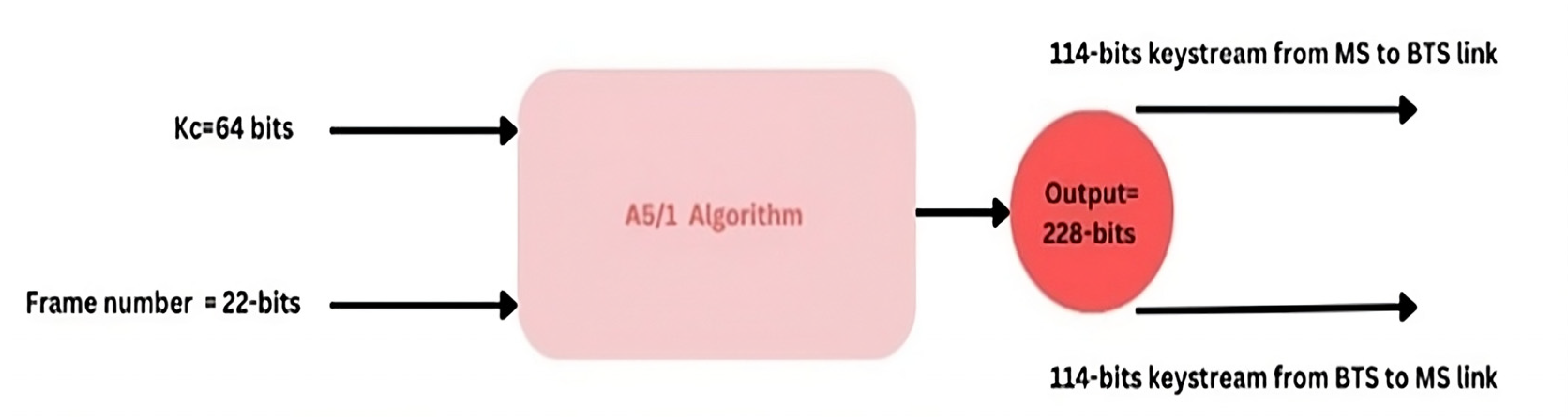
The A5/1 algorithm is utilized for the encryption of data in GSM. For this purpose, 64 bits Kc generated by A8 algorithm are used with a 22-bit frame number denoted as Fn. During the call, the frame number changes, but the session key (Kc) remains the same. Using Kc and the 22-bit frame number, the A5/1 algorithm outputs a 228-bit key stream for the duplex link. A total of 114 bits of this 228-bit keystream are used for MS to BTS link while the rest of 114 bits are used for the BTS to MS link [
44,
45]. In order to perturb the position of bits, the A5/1 algorithm uses three registers called linear feedback shift registers (LFSR) of lengths of 19, 22, 23 bits. These registers are denoted by R1, R2, and R3 as illustrated in
Figure 3.
When the bits are moved to three shift registers, a majority function is applied to select two registers as successors. The step-by-step process of shift register utilization, majority function application and successor selection is shown in
Figure 3. After the bits are shifted to the respective registers, a majority rule is applied to elect the successor [
46,
47,
48].
For this purpose, bits from position C1, C2, and C3 are picked from R1, R2, and R3 registers, respectively. The majority rule picks two successors based on bit one or bit zero. The position, with maximum numbers of 1s or 0s will become the successor, like in our example the register R1 and register R3 are the successors as there are two 1s and one 0. In the next step, the two registers R1 and R3 are stepped forward. In register R1, bits are at the position 13th, 16th, 17th, and 18th are taken and XORed with each other. The result is saved at LSB by shifting the register values to the right side. Similarly, from the register R3, the bits from position 7th, 20th, 21st, and 22nd are picked and XORed with each other, saving the result at LSB.
The following steps are used to generate keystream bits from frame counter Fn and session key Kc.
Step 1: The three registers are first initialized as zeroed; the clock will continue till 64 cycles are completed. In this step, each bit of session key (Kc) is XORed in parallel with the MSB’s (Most significant bits) of each register.
Step 2: Now the three registers are clocked for additional cycles with a stop or go clock control. In the second step, 22-bits of frame number Fn are again XORed in parallel with the MSB’s of the three registers, respectively.
Step 3: In this step, the three registers are clocked for 100 additional cycles with a stop or go control. Clocking follows the majority rule. Majority bit is determined based on clocking bit of registers (LFSR1 clocking bit: C1 = 8th bit, LFSR2 clocking bit: C2 = 10th and LFSR3 clocking bit: 10th bit). If the clocking bit of any register is the same as the majority bit, the register is clocked. This process is performed just to mix the frame number (Fn) and session key (Kc) together.
Step 4: In step 4, the three registers are clocked 288 times with stop or go control so that two 114-bit sequences of the output keystream are produced. As shown in
Figure 4. The output keystream bits of each register at every cycle are XORed with 114-bits of the plaintext [
41].
4. Materials and Methods
Within Cellular Technology, the safeguarding of user data is achieved through the utilization of the A5/1 method. This technique operates by partitioning a 64-bit session key into three distinct registers, namely R1, R2, and R3. The registers are subsequently integrated with a predetermined algorithm to produce encrypted data. According to reference [
49]. While the encryption process employed by GSM is considered to be secure, it is worth noting that there is currently no established probabilistic model available for analyzing the likelihood of breaking or intercepting the Kc key. Hence, it is vital to formulate a term that can be utilized for the evaluation of the security of the encrypted data. Moreover, the security of the A5/1 algorithm can be strengthened by utilizing a greater number of registers in accordance with a predetermined norm. The resolution to the issue posited in this scholarly article entails the culmination of comprehensive literature reviews encompassing books, conference proceedings, and journal articles. A probabilistic model was constructed and subsequently implemented in MATLAB
® R2020b for the purpose of conducting simulations. The model underwent refinement through the process of variable tuning and parameter narrowing to achieve optimal outcomes.
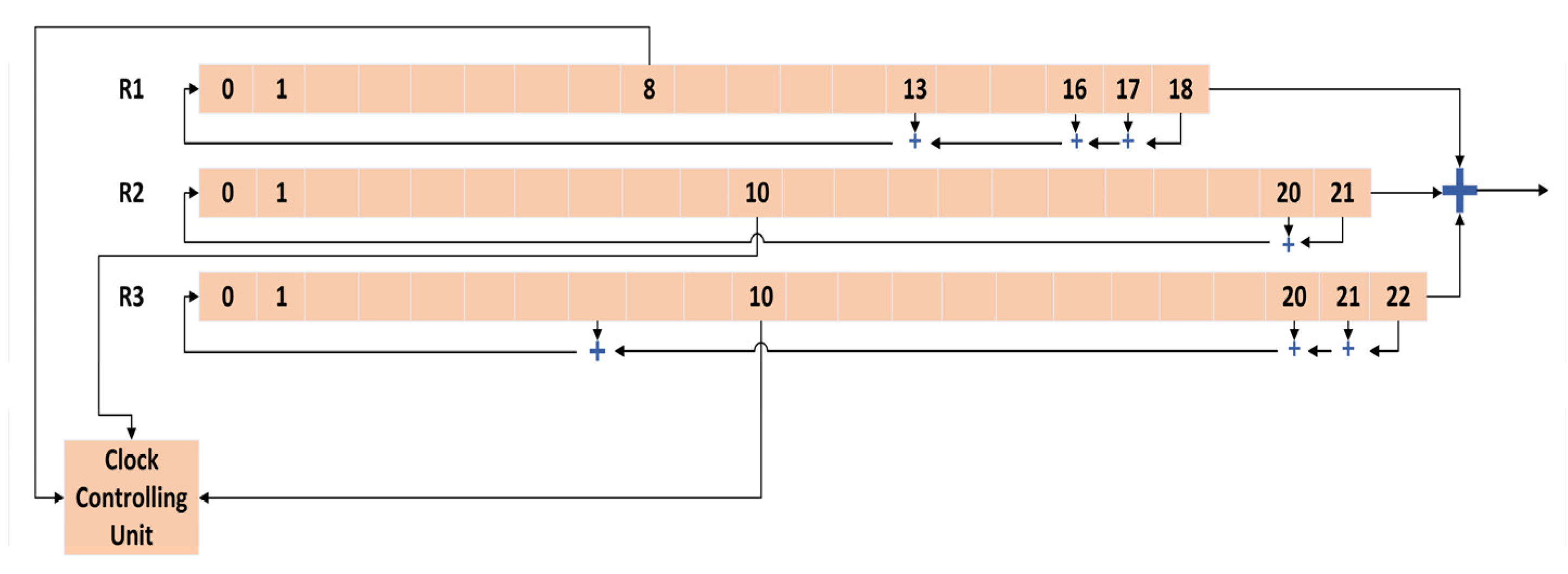
Furthermore, the reported results were derived using comprehensive simulations that involved the establishment of various security environments. This was performed to assess and confirm the efficacy of the suggested method. The A5/1 encryption algorithm is widely recognized and is used for encryption in Mobile Communication Systems. During the decryption process, the A5/1 algorithm uses a session key, also known as Kc, together with a frame number that is 22 bits long. The A5/1 method makes use of three linear feedback shift registers (LFSRs), each of which has a length of 19, 22, and 23 bits, respectively. These registers are indicated by the letters R1, R2, and R3. The individual segments of each register are subjected to an XOR operation, resulting in the combination of their values. This combined value is then subjected to another XOR operation, representing a single bit of the keystream. The predetermined tap positions of each register are established in advance. The bit positions of register R1 are located at places 13, 16, 17, and 18. The tap positions of register R2 are situated at positions 20 and 21.
Similarly, the bit positions of register R3 may be found at positions 20, 21, and 22, as depicted in
Figure 5. The registers are sequentially timed using a majority rule mechanism. Every register in the system is equipped with a clocking bit, denoted as bit 8 for register R1, bit 10 for register R2, and bit 10 for register R3. During each iteration, the majority function is implemented on the clocking bits. Following the application of the majority function, the subsequent registers are chosen for further processing. The generation of keystream bits is facilitated through the utilization of a session key (Kc) and a frame counter (Fn). The three linear feedback shift registers are initialized with a value of zero. These registers undergo 64 clock cycles, during which each bit of Kc is simultaneously XORed with the preceding XORed bits of each register.
Subsequently, the 22-bit frame number undergoes an XOR operation with the feedback of each register. The procedure, as mentioned above, persists for a total of 22 cycles. Subsequently, the registers undergo a clocking process spanning 100 extra cycles, after which the majority rule is applied. The registers are timed for a total of 228 cycles, resulting in the generation of two 114-bit sequences known as keystream bits, which are obtained by XORing the output of each register. This technique is performed utilizing three registers; nevertheless, it is possible to augment the number of registers to bolster security. To enhance data protection, it is possible to augment the number of registers. However, it is crucial to ensure that the number of registers is odd, such as 5, 7, or 9, in order to maintain the functionality of the majority function. If an even number of registers is employed, the majority function may fail to operate effectively, resulting in a tie scenario.
- (A)
Proposed GSM Encryption Mechanism
As previously said, the protection of data consistently remains a significant priority throughout the research community. The dynamic nature of methods and system manipulation poses a significant problem for GSM technology. In the context of data encryption, the conventional GSM technology employs a trio of linear feedback shift registers as an initial stage. Therefore, it is imperative to enhance encryption methodologies in order to seamlessly integrate a secure mechanism with GSM without any detrimental consequences. The provided text consists of a series of numbers [
50,
51,
52]. In order to fulfill this objective, a novel data security architecture is presented, which leverages a greater number of shift registers.
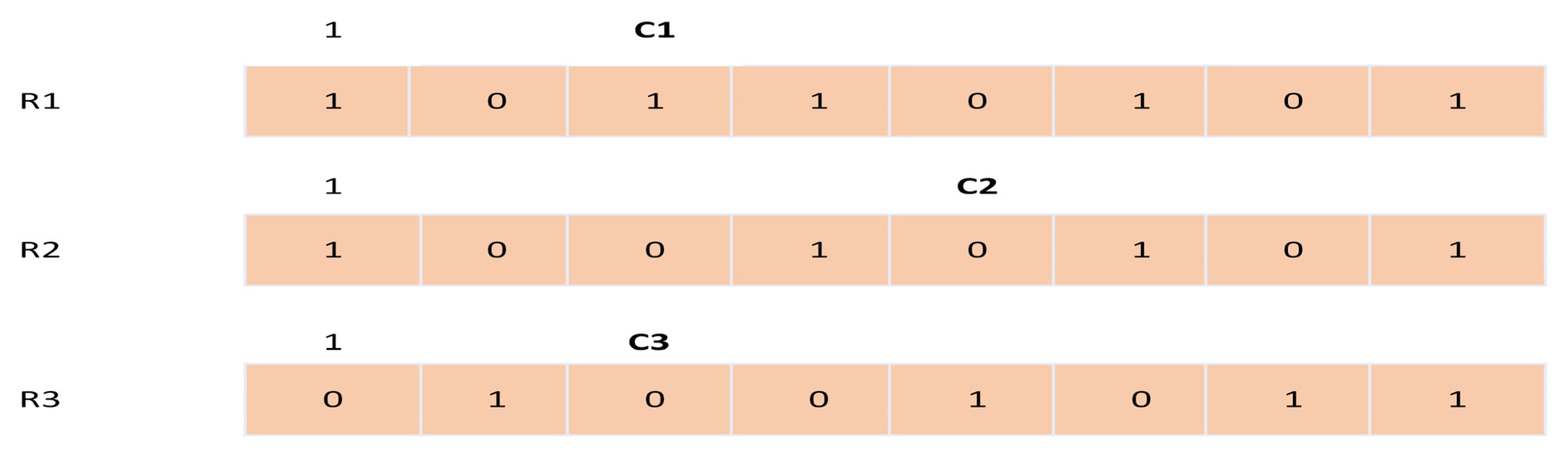
Additionally, a computational model has been formulated to determine the maximum number of registers required to store the 64-bit key. This section presents three scenarios: encryption utilizing five registers, encryption employing seven linear feedback shift registers, and encryption utilizing nine registers. The majority function is employed to determine the registers that will undergo subsequent perturbation, hence increasing the difficulty for potential attackers in discerning the bit arrangement within a register. The operational dynamics of the majority function can be observed in
Figure 6, where three Linear Feedback Shift Registers (LFSRs) are utilized, with each register possessing a length of 8 bits.
R2 and R3 linear feedback shift registers are successors. Other steps are almost the same to make a keystream bit for each direction for BTS to MS and for MS to BTS.
This study is primarily theoretical and relies on simulation-based analysis without implementation in real GSM hardware or networks. The increased number of LFSRs, while improving security, may introduce additional computational complexity, which has not been fully evaluated in terms of processing time, power consumption, or resource constraints in mobile devices. Moreover, the impact of the proposed modifications on GSM protocol compatibility and interoperability with existing infrastructure has not been assessed.
- (B)
Example Scenario
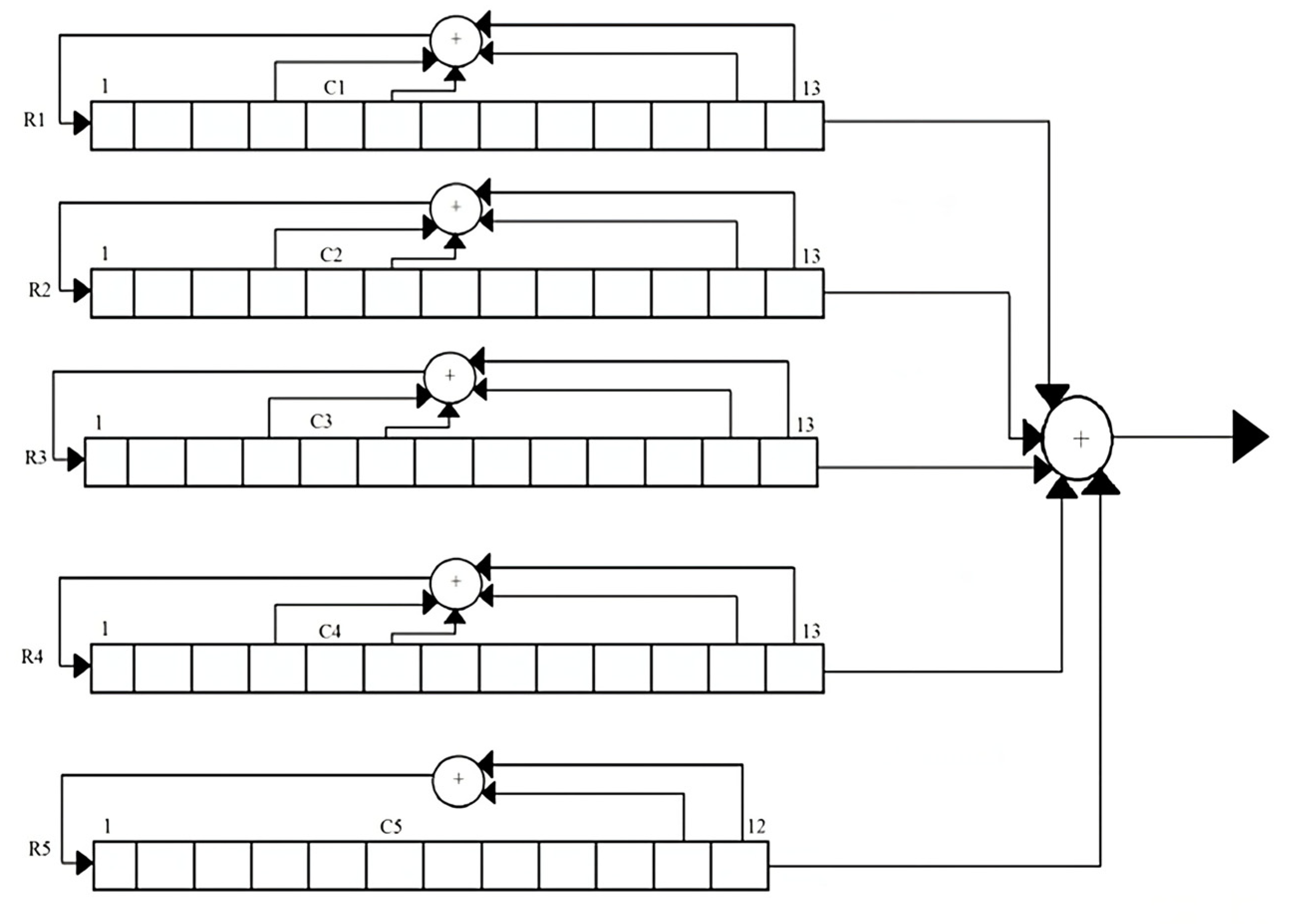
In the given illustration, we augment the register count from 3 to 5, 7, and 9 in order to enhance the security and protection of our data. By maintaining a consistent length of Kc and increasing the number of registers, the likelihood of data loss can be minimized.
When considering the expansion of the register count, it is important to note that the minimum number of bits required should not be less than 2 bits. Each register comprises a minimum of two bits, allowing for the application of the XOR operation. As an illustration, when the bits of Kc are partitioned into five registers, the initial four registers encompass 13 bits apiece, while the fifth register comprises 12 bits.
The registers are denoted as R1, R2, R3, and R4, each possessing a length of 13 bits. Additionally, there is a register named R5, which has a length of 12 bits. The resulting keystream is obtained by performing an XOR operation on the output values of all registers. The XOR operation is applied to the predetermined bits of each register, and the resulting values are then inputted to the left side of each register. The taps of registers R1, R2, R3, and R4, which are subjected to the XOR operation, are located at the 4th, 6th, 12th, and 13th places inside the bit sequence.
The XOR operation is used for the taps of R5, specifically at bit positions 11 and 12. The implementation of a majority rule mechanism synchronizes the registers. The registers R1, R2, R3, and R4 each possess a clocking bit located at position 5. The fifth register in the system is equipped with a clocking bit located at position six, as illustrated in
Figure 7. The state of the clocking bit in each of the five registers is recorded, and the majority bit is determined during each cycle. The sole registers that are timed are those that align with the majority bit. When a register is subjected to a clock signal, the taps within the register are subjected to an XOR operation, and the resulting output is then stored in the leftmost position of the register. The keystream is generated by performing an XOR operation on the outputs of each register. The identical process is employed on each register in the A5/1 algorithm for GSM in order to obtain the keystream at the conclusion.
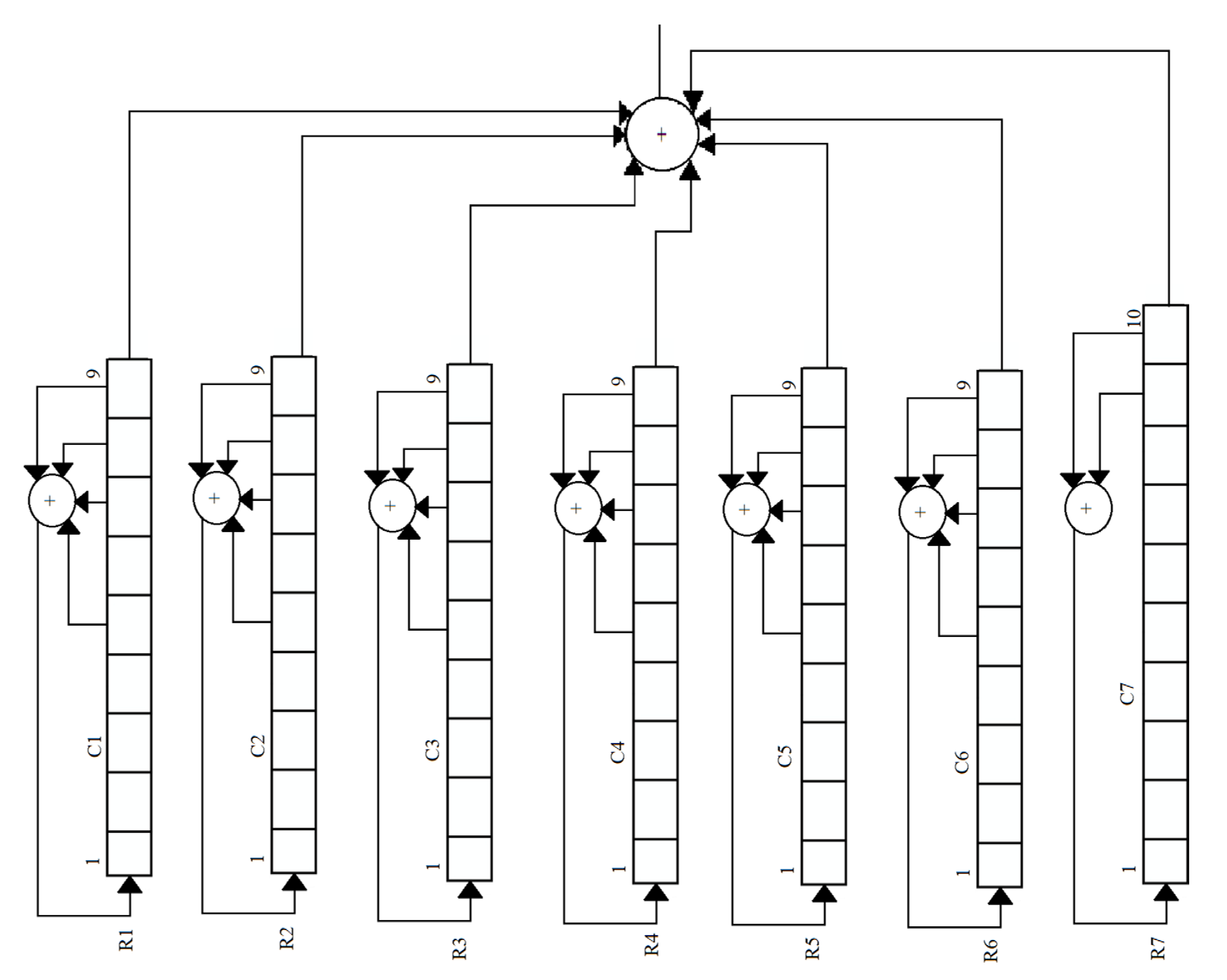
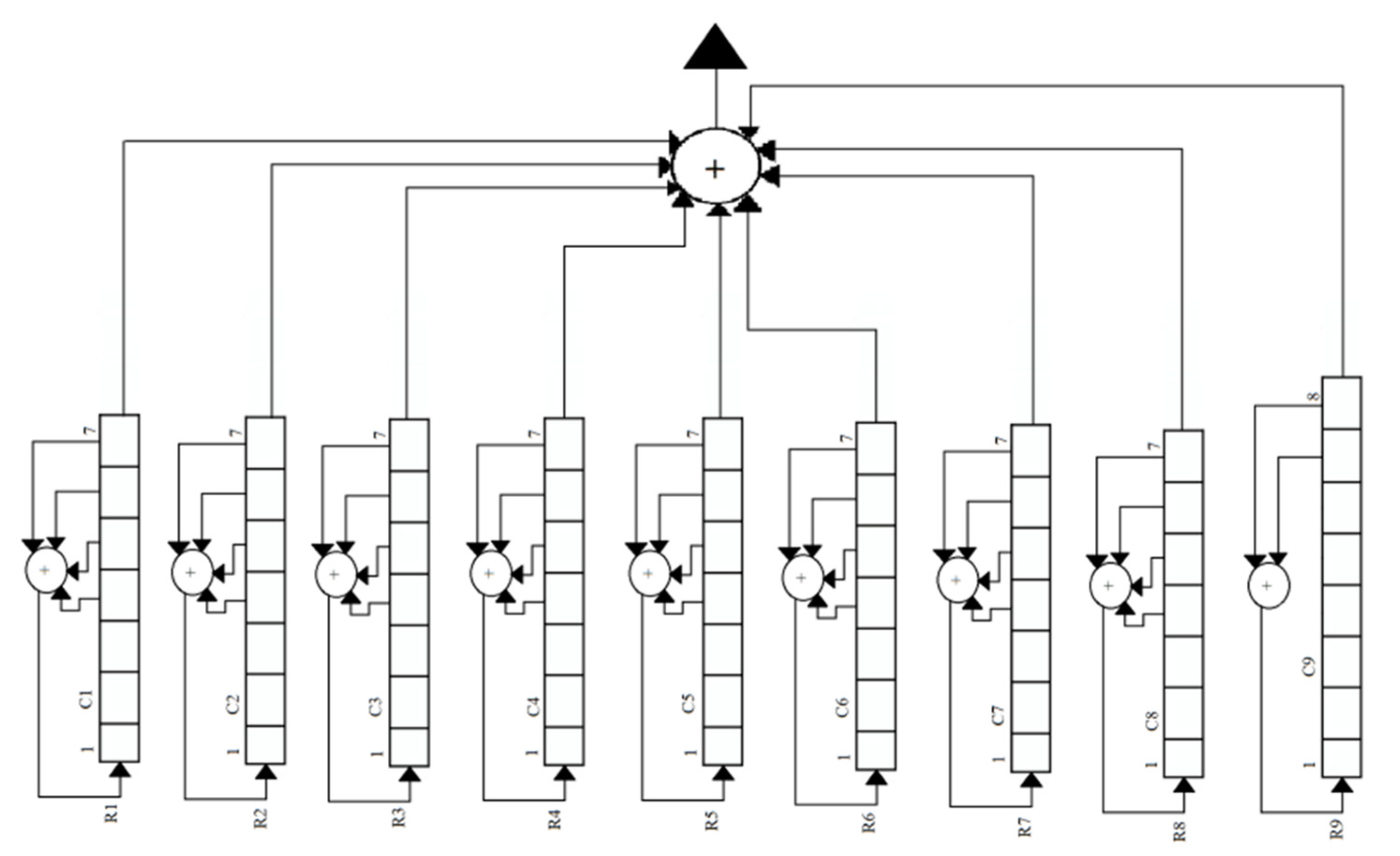
Increasing the length of registers from 3 to their maximum capacity enhances the security and protection of personal or confidential data through encryption mechanisms. The registers are partitioned in a manner that ensures each register has a length greater than or equal to 2 bits as shown in
Figure 8. This is necessary in the A5/1 method to ensure effective application of the XOR operation. Additionally, it is important to consider that the quantity of registers should be odd, such as 3, 5, 7, 9, etc. This is because an even number of registers would not allow for the application of the majority rule, as there is a possibility of a tie in certain situations. Increasing the number of registers irregularly enhances the security of data. The vulnerability level of the interception method may substantiate this assertion.
Additionally, it is discussed how to determine the interception risk level of various registers and demonstrated that when the number of registers rises to a certain point, the interception vulnerability level declines.
- (C)
The Proposed Probabilistic Model for Interception in GSM:
In GSM, each user’s data is protected via the A5/1 algorithm, which divides a 64-bit session key into three registers: R1, R2, and R3. As a result, an expression must be created to assess the encrypted data’s security. Furthermore, by using more than three registers with a preset rule, the security of the A5/1 method can be improved.
By increasing the number of shift registers, it is possible to increase data encryption. The proposed system handles the additional number of registers in such a way that the length of the session key Kc is unaffected and remains the same as specified by the GSM standard, given in Algorithm 1 as follow.
| Algorithm 1: Algorithmic Enhancements for Secure A5/1 Stream Cipher Implementation with Increased Registers: |
- -
n: the session key Kc’s number of bits - -
D: distinct registers (values 3, 5, 7, 9, …) - -
C6: All possible combinations of bits
- 2.
Compute Cb using the formula
Cb = (if [Kc * (n − 2D + d)/d]x ∑ [from f = 0 to (*)]) (3)- 3.
Compute the probability of interception, pb:
Pb = function (cb)
Note: the function is not provided in the content, but pb is inversely related to Cb.
- 4.
Check the vulnerability:
If Cb increases, then- -
The probability of interception (Pb) decreased - -
Data becomes more secure
- 5.
Increase D (number of registers) to enhance security:
While (desired security is not achieved)- -
Increase D by 2 (since D can take values 3, 5, 7, 9) - -
Compute Cb using step 2 - -
Compute Pb using step 3
- 6.
End
|
It is possible to write the produced calculation for how many different ways an n-bit encryption key may be used in D different registers as
where
is the sum of all possible bit combinations. P
1 represents the product of combinations based on the register configuration, while P
2 models a binomial mutation process.
P
1 and P
2 can be given as follows:
where n is the session key
bits. There are D separate registers that can accept the numbers 3, 5, 7, and 9. d is the index that starts from 1 and goes up to D-1 value. Each register can take any length, with a minimum of two bits. C
b can be written as
The probability of interception for the proposed scheme is given below:
where P
b is the probability of interception.
is the total number of bit combinations in the participating shift registers. This implies that if the number of combinations of
is increased, the probability of interception of the data will be decreased and vice versa.
According to the link between the number of registers and the susceptibility level of interception, when registers are added, more bit combinations are possible, but the vulnerability degree of interception lowers. In other words, as the number of choices grows, the risk of eavesdropping lowers, and the security and protection of our data improve.
5. Results
In the coming subsections, we provide graphs showing the total number of options and the degree of interception vulnerability when registers are increased. The graphs demonstrate that as the number of registers rises, so does the number of possible bit combinations, but the susceptibility to intercepting the session key (Kc) falls.
Figure 9 depicts the link between the number of registers and the number of combinations. The graph demonstrates that as the number of registers rises, so does the total number of bit combinations.
After a specific point, while increasing the number of registers, the combinations of bits start decreasing. Keeping the length of the session key constant, all possible registers versus combinations are shown in
Figure 10. There are a maximum number of combinations at a specific number of registers, i.e., 19. The total number of combinations decreases even if the number of registers is increased beyond the number 19.
Figure 11 illustrates a correlation between the number of registers and the vulnerability level of interception. As the number of registers increases, there is a decrease in vulnerability, resulting in enhanced security and protection of data and personal information. This implies that by increasing the registries, the protection of personal or confidential data is enhanced, hence reducing the vulnerability to data breaches.
As the amount of vulnerability in interception diminishes, the susceptibility of the data to compromise is correspondingly reduced. Therefore, it can be demonstrated that when the number of registers in GSM is raised, the number of possible bit combinations also increases, resulting in a decrease in the vulnerability level of interception. The personal data is protected in a manner that reduces its vulnerability to hacking or theft of information.
According to the findings presented in
Figure 12, there is a clear correlation between the rise in session key size and the subsequent increase in the number of possible combinations. This increase in combinations directly contributes to a decrease in the vulnerability level of interception. The graph depicted below exhibits a non-linear relationship, although, when plotted on a logarithmic scale, it appears to be linear.
The mathematical formulation for the number of combinations created with an arbitrary key size n and segmentation group registers D was derived using the method of mathematical induction, as depicted in
Figure 13. In order to achieve this objective, a distinct sequence of combinations was generated by utilizing different odd values for the segmentation group registers D while maintaining a fixed key size of n = 8 and n = 16, respectively as shown in
Table 2.
In
Figure 14, subplot (a) illustrates the correlation between the quantity of registers (D) and the potential number of combinations (combinations). Every individual bar depicted in the plot represents a distinct value of ‘n,’ which corresponds to the size of the cryptographic key. As an illustration, the initial bar represents the values D = 3 and n = 8, indicating that in this particular situation, there exists a total of six potential arrangements of bits within the registers. Likewise, the remaining bars depict various permutations of the letters ‘D’ and ‘n’ together with their respective potential arrangements.
Subplot (b): The relationship between vulnerability level and registers the subplot labeled as (b) serves to demonstrate the correlation between the number of registers (D) and the susceptibility to interception. The vulnerability level exhibits an inverse relationship with the number of combinations, whereby an increase in the number of combinations results in a drop in the vulnerability level. The plot illustrates a negative correlation between the vulnerability level and number of registers, demonstrating that the risk level decreases as the number of registers grows and there are more registers.
Figure 15’s subplot (a) depicts a graphical depiction of the distribution of feasible combinations over many registers (D). The data indicated the occurrence of several conceivable combinations by varying the value of “D”. The histogram illustrates the distribution of combinations and their variations across various registers count effectively.
Using a histogram, subplot (b) investigates the link between vulnerability level and registers. The distribution of vulnerability levels across various numbers of registers (D) is shown in the histogram subplot (b). The data shows how different levels of vulnerability arise at different rates for different values of ‘D.’ The plot makes it simpler to comprehend the link between the vulnerability level and the number of registers. As well as the frequency with which certain vulnerability levels occur.
Figure 15’s subplot (a) depicts a graphical depiction of the distribution of feasible combinations over many registers (D). The data indicated the occurrence of several conceivable combinations by varying the value of “D”. The histogram illustrates the distribution of combinations and their variations across various registers count effectively. The association between the number of registers, possible combinations, and degrees of vulnerability in the suggested encryption method may be understood with the use of both datasets. This study shows how increasing the number of registers can improve data security and reduce risks.


