Article

Mechatronic and Robotic Systems Utilizing Pneumatic Artificial Muscles as Actuators

1
Department of Robotics and Production System Automation, Faculty of Mechanical Engineering and Naval Architecture, University of Zagreb, I. Lučića 5, 10000 Zagreb, Croatia
2
Computer Science and Machine Learning Research Group, School of Applied Mathematics and Computer Science, University of Osijek, Trg Ljudevita Gaja 6, 31000 Osijek, Croatia
*
Author to whom correspondence should be addressed.
Inventions 2025, 10(4), 44; https://doi.org/10.3390/inventions10040044
Submission received: 1 May 2025 / Revised: 13 June 2025 / Accepted: 17 June 2025 / Published: 23 June 2025
(This article belongs to the Section Inventions and Innovation in Advanced Manufacturing)

Abstract

This article presents a series of innovative systems developed through student laboratory projects, comprising two autonomous vehicles, a quadrupedal walking robot, an active ankle-foot orthosis, a ball-on-beam balancing mechanism, a ball-on-plate system, and a manipulator arm, all actuated by pneumatic artificial muscles (PAMs). Due to their flexibility, low weight, and compliance, fluidic muscles demonstrate substantial potential for integration into various mechatronic systems, robotic platforms, and manipulators. Their capacity to generate smooth and adaptive motion is particularly advantageous in applications requiring natural and human-like movements, such as rehabilitation technologies and assistive devices. Despite the inherent challenges associated with nonlinear behavior in PAM-actuated control systems, their biologically inspired design remains promising for a wide range of future applications. Potential domains include industrial automation, the automotive and aerospace sectors, as well as sports equipment, medical assistive devices, entertainment systems, and animatronics. The integration of self-constructed laboratory systems powered by PAMs into control systems education provides a comprehensive pedagogical framework that merges theoretical instruction with practical implementation. This methodology enhances the skillset of future engineers by deepening their understanding of core technical principles and equipping them to address emerging challenges in engineering practice.

1. Introduction

In the advancing field of mechatronics and robotics, the demand for actuators that exhibit adaptability, lightweight construction, and safe human interaction is steadily increasing. Pneumatic artificial muscles (PAMs), originally inspired by the structure and function of human skeletal muscles, have emerged as a promising alternative to conventional actuators. They offer inherent compliance, energy efficiency, and silent operation [1]. These soft, contractile actuators are particularly advantageous in applications where safety and physical interaction with humans are essential, such as in wearable assistive devices, robotic limbs, and collaborative robotic systems [2,3,4,5]. Recent developments in PAM research have progressed beyond fundamental actuation, encompassing advanced modeling techniques and control strategies tailored to the muscles’ highly nonlinear and time-varying dynamics. To address these complexities, several approaches have been proposed, including adaptive backstepping sliding-mode control frameworks [6], dynamic models for bidirectional PAM actuators [7], and neural network-based control schemes that enhance system adaptability and robustness under uncertainty [8,9]. Furthermore, self-organizing fuzzy logic controllers [10], operator-based phenomenological scalar hysteresis models [11], and model predictive control algorithms [12] have contributed to improved controllability, responsiveness, and safety of PAM-driven systems. Despite these advantages, including compliance, low weight, and bioinspired motion, PAMs remain challenging to control due to their intrinsic nonlinearities, sensitivity to environmental variations, and inconsistent performance under dynamic loading conditions. These limitations have led to a growing interest in hybrid control strategies that combine model-based and data-driven methods. Such strategies increasingly incorporate real-time feedback, machine learning, and predictive algorithms to address system uncertainties and enhance performance. PAMs have been successfully implemented in a wide range of applications, including orthotic devices, rehabilitation robotics, legged robots, and soft manipulators. Wearable robotic systems such as active ankle-foot orthoses benefit from PAMs’ ability to deliver biomechanically inspired assistance that closely replicates natural human movement. Moreover, their integration into fully soft robotic platforms has enabled the development of autonomous systems capable of adaptive locomotion over unstructured terrain.
This article presents a series of experimental mechatronic and robotic systems that employ PAMs in practical, application-oriented contexts. These include a quadrupedal walking robot, an active ankle-foot orthosis, and several functional and educational robotic platforms. While the primary focus is on the application-level integration of PAMs, the discussion also addresses key aspects of system design, control architecture, and mechanical implementation. By showcasing real-world PAM-powered systems, this work aims to bridge the gap between biologically inspired actuation technologies and their practical deployment in educational, medical, and service robotics. Simultaneously, it emphasizes the ongoing need for advancement in modeling techniques and control theory to fully realize the potential of soft actuators.

2. Materials and Methods

This section presents a series of distinctive demonstrative systems actuated by PAMs, developed as test platforms within the domains of pneumatic systems and automatic control. The discussion begins with robotic systems, including the design and construction of a quadrupedal walking robot and a planar manipulator arm with one degree of freedom (1DOF), both actuated by PAMs. Subsequently, two autonomous vehicles powered by PAMs are introduced. Following the robotic systems, two unique mechatronic platforms are described: a ball-on-beam system and a ball-on-plate system. These configurations are representative examples of unstable, underactuated, multivariable systems characterized by highly nonlinear dynamics. Finally, the design and construction of a prototype of an actively powered ankle-foot orthosis is presented. This device is intended to restore functional mobility, providing targeted assistance for rehabilitation in individuals experiencing reduced or lost lower limb function.

2.1. Robotic Systems

Inspired by human musculature, pneumatic artificial muscles (PAMs) are transforming the field of robotics by enabling lifelike, biologically inspired movements. These actuators closely replicate the contraction and flexion mechanisms of human muscles, making them highly suitable for applications that require realistic and sensitive robotic motion. Their distinctive advantages, including lightweight construction, high power-to-weight ratio, and compliance with environmental interactions, enable PAMs to deliver smooth, precise, and responsive actuation. These characteristics significantly enhance robotic agility and adaptability, particularly in legged robots operating in complex or unstructured environments. By enabling robots to exhibit more natural and human-like movements, PAMs are facilitating advancements across diverse applications and ushering in a new era of innovation in robotic systems.
Mobile robotics, a dynamic and rapidly advancing field, encompasses various research areas, including the development of biologically inspired systems that emulate the locomotion of humans and animals. As a multidisciplinary domain, it integrates principles from mechanical, electrical, and software engineering. A notable subfield within this area is legged robotics, which offers distinct advantages over traditional wheeled or tracked platforms. Unlike wheeled robots, which are limited in their ability to navigate uneven terrain, legged robots can dynamically adjust their gait and step length to adapt to complex environments. This capability makes them highly versatile and effective in scenarios that demand robust locomotion and terrain adaptability. The pursuit of robotic systems that emulate natural organisms has led to the development of a wide range of walking robots, drawing inspiration from the biomechanics of humans, quadrupeds (e.g., dogs and horses), insects, and even centipedes. Resulting designs include monopods, bipeds, quadrupeds, hexapods, and octopods [13,14,15,16,17,18]. These biomimetic systems frequently incorporate pneumatic muscle actuators due to their mechanical similarity to biological muscles, making them a natural choice for actuation in such applications. While wheeled robots offer advantages in speed and mechanical simplicity on flat surfaces, they are less effective in uneven or dynamically changing environments. In contrast, walking robots exhibit superior mobility, stability, and environmental adaptability, achieved using PAMs that mimic the efficiency and dynamics of biological muscle systems.
As a testament to their potential, autonomous quadrupedal robots actuated by PAMs have been successfully implemented, demonstrating their applicability in real-world conditions, including harsh and unstructured environments. An example of such a robot is presented in the following section.

2.1.1. Four-Legged Walking Robot Actuated by PAMs

In response to the growing interest in mobile robotics, a project was initiated to develop WRAPAM (Walking Robot Actuated by Pneumatic Artificial Muscles), a quadrupedal walking robot inspired by the biomechanics of horses and dogs. The system integrates four primary components: an energy subsystem for supplying compressed air, pneumatic actuators for joint articulation, a control unit for information processing and coordination, and a sensor suite for environmental perception. The custom-designed robot features two degrees of freedom (2DOF) per leg, with actuation provided by eight Festo pneumatic muscles (model DMSP-20-150N-AM-CM). A modular valve terminal system equipped with eight solenoid coils is employed to control the movement of the robot. Each leg consists of two actuated rotational joints and incorporates a torsional spring to enhance joint agility and mechanical compliance. The robot’s compact electronics module houses an Arduino Mega (ATmega2560 microcontroller) (Microchip Technology Inc., Chandler, AZ, USA), selected for its affordability, widespread availability, and extensive set of input/output ports, which facilitate future system expansions. Signal amplification for driving the pneumatic valves is achieved using an integrated ULN2803A chip. Wireless communication is enabled via a Bluetooth module, allowing for remote interaction between the robot and its operator. All components of the compressed air supply system and control unit are precisely arranged on a custom-built aluminum frame to ensure optimal weight distribution and balance. The fully autonomous quadrupedal robot, depicted in Figure 1, supports both Bluetooth and USB interfaces for computer-based configuration and control.
The control strategy for the WRAPAM robot is based on biologically inspired locomotion, specifically emulating the natural gait of quadrupeds such as horses. A trot gait pattern is implemented, in which diagonal leg pairs move simultaneously while the remaining two legs remain grounded to maintain static stability. Each pneumatic muscle is actuated using pre-programmed timing sequences, without closed-loop feedback. The actuation timing is finely regulated through flow control valves, which adjust the filling and venting durations of the muscles. These timings were determined experimentally to achieve consistent and repeatable gait cycles. The robot’s locomotion is governed by a program executed on the onboard ATmega2560 microcontroller. The control logic manages sequential leg movements and precisely timed muscle actuation to enable bidirectional motion. While programming and monitoring can be performed via USB, Bluetooth communication is utilized in autonomous mode to interface with a mobile application, available online, which serves as the user interface for motion control.
Operational testing confirmed that the robot is capable of walking continuously for approximately 20 min at an average speed of 0.15 m/s. The gait exhibited stability during both forward and reverse motion. Repeatability was verified across multiple trials, with minimal variation in step timing. Each leg joint achieved a functional range of motion sufficient for effective gait, driven by pneumatic muscle actuation. The robot’s resilience to minor disturbances was also validated. In the event of communication failure, the robot automatically ceases movement and remains stationary until the Bluetooth connection is reestablished, thereby enhancing operational safety and reliability in mobile robotic applications (see attached video S1 in Supplementary Materials).
Although the WRAPAM system was introduced primarily as a hardware demonstration platform, particular emphasis was placed on achieving coordinated locomotion using a biologically inspired gait. The selected trot pattern ensures that diagonal leg pairs move simultaneously, which allows the robot to maintain static stability while walking. This approach simplifies the control requirements while preserving a realistic and repeatable gait sequence. The gait cycle was designed through iterative testing, in which activation timings for each pneumatic muscle were manually tuned to achieve smooth transitions between stance and swing phases. Even though the control is open-loop and does not include real-time feedback, the timing parameters were adjusted to synchronize joint motions across all four legs, ensuring that the robot can move in a stable and balanced manner. Initial tests on flat indoor surfaces demonstrated that the robot could maintain continuous locomotion without loss of balance or irregular gait patterns. The robot’s ability to recover from small disturbances and to stop safely in case of communication loss further supports the robustness of the implemented strategy. These results serve as a preliminary validation of both the mechanical design and the control approach, and form the basis for future work focused on integrating sensors and developing adaptive, closed-loop gait control.

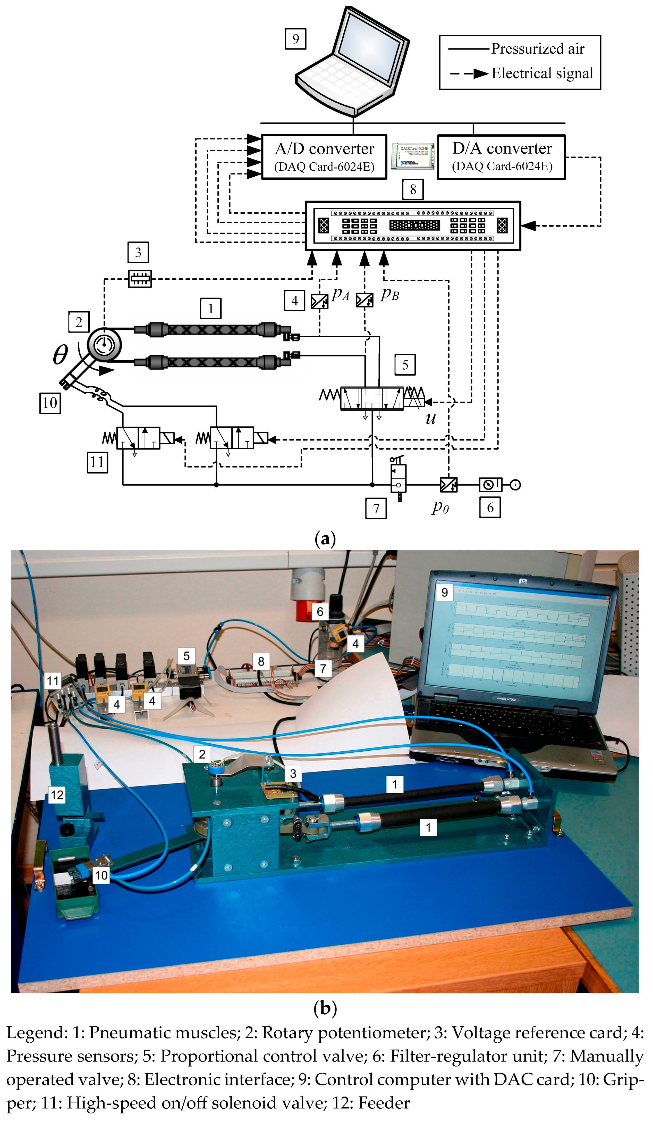
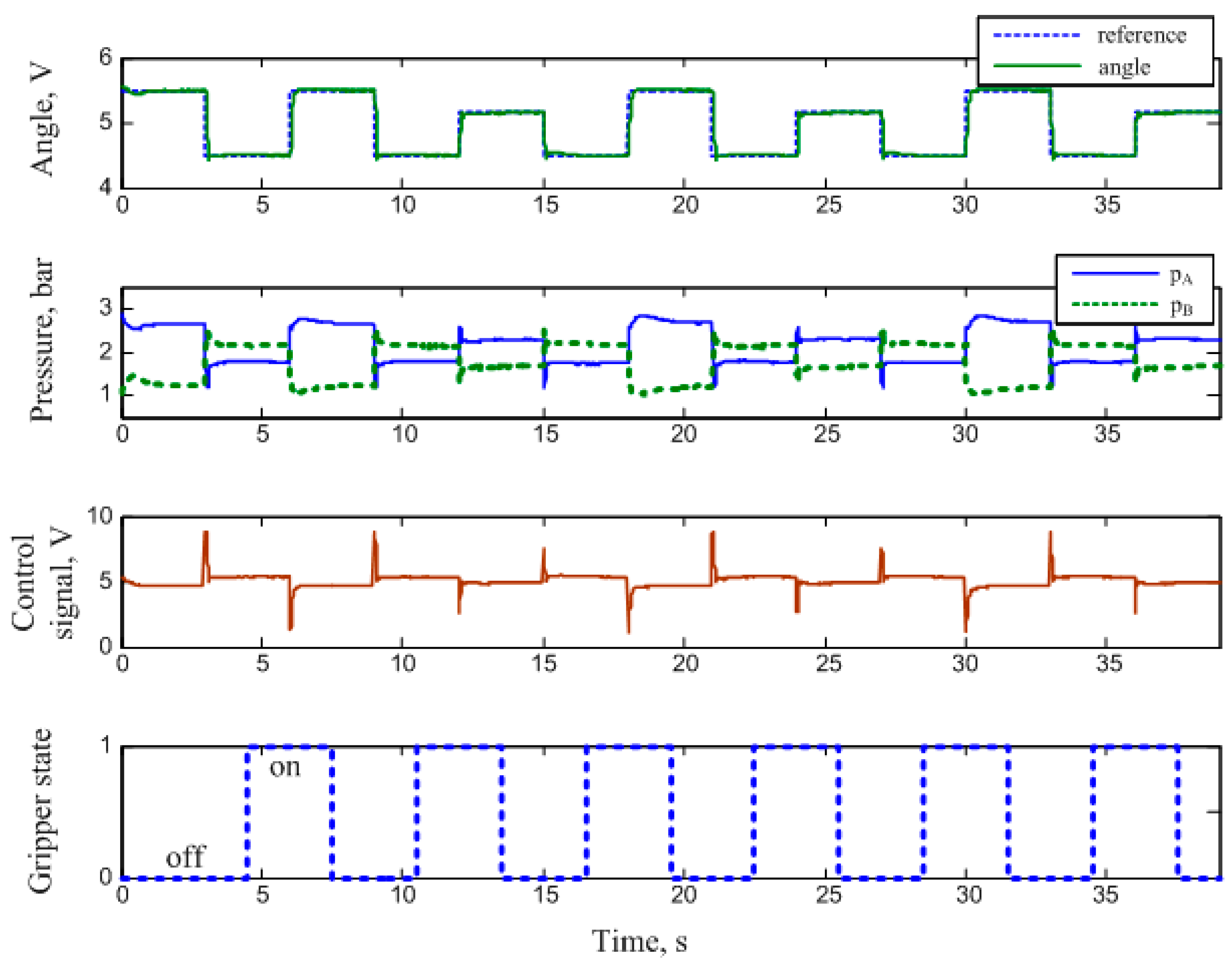
2.1.2. Manipulator Arm Actuated by PAMs

PAMs exhibit substantial potential for industrial applications, particularly in the field of assembly automation. Their compact form factor, high strength-to-weight ratio, intrinsic safety, and mechanical simplicity render them highly suitable for advanced robotic manipulation systems. The antagonistic configuration of PAM actuators, illustrated in Figure 2, mimics the biological biceps-triceps arrangement, highlighting the functional similarity between PAMs and human skeletal muscles. These actuators, powered by compressed air, contract along their longitudinal axis as they expand radially, thereby transforming radial expansion into axial contraction. Typically, PAMs can achieve a maximum contraction of approximately 25% of their nominal length. To enable bidirectional motion, actuators must be arranged in an antagonistic configuration. In this arrangement, two PAMs emulate the function of a human elbow joint, acting as an antagonistic pair (analogous to the biceps and triceps) to produce joint rotation. As pressure increases in one muscle, it is simultaneously reduced in the opposing one, generating torque through differential contraction, like biological muscle operation. The control signal directed to each valve regulates the internal pressure of the muscles, resulting in coordinated antagonistic actuation that drives the rotation of the manipulator arm. The experimental setup comprises two primary subsystems: a pneumatic system responsible for actuation and a control system that manages signal processing and valve regulation.
The pneumatic system consists of an air supply unit (SMC EAW 2000-F01)(SMC, Sotokanda, Chiyoda-ku, Tokyo, Japan), a proportional directional control valve (Festo MPYE-5-1/8 HF-010B)(Festo, Esslingen, Germany), and two opposing PAMs (Festo MAS-10-220N-AA-MC-K)(Festo, Esslingen, Germany) arranged in an antagonistic configuration to generate joint rotation. Torque is produced by the pressure differential between the antagonistic muscles, which actuate a lever connected to a pneumatic gripper (Festo HGP-06-A) (Festo, Esslingen, Germany). Internal pressure within each muscle and the system’s overall supply pressure are continuously monitored using pressure transducers (SMC ISE4-01-26) (SMC, Sotokanda, Chiyoda-ku, Tokyo, Japan). Joint angular displacement (θ) is measured using a single-turn potentiometer, which provides real-time feedback to the control system. Signal processing is carried out by a control computer equipped with a data acquisition card (NI DAQCard 6024E for PCMCIA), featuring a 12-bit analog-to-digital and 12-bit digital-to-analog converter. This closed-loop configuration enables the manipulator arm to execute precise pneumatic-driven motion. The control algorithm computes appropriate valve control signals to regulate airflow, thereby adjusting the arm’s position. Sensor feedback ensures accurate arm tracking, while a high-speed valve is used to actuate the gripper at the desired location. An example of the manipulator arm transferring roller workpieces from a feeder to a collection box is depicted in Figure 3 [19]. The system demonstrates significant compliance due to the inherent elasticity of PAMs, which enhances safety during human–robot interaction but introduces control complexity. Hysteresis effects were observed during repeated actuation cycles, manifesting as positional lag that varied with the actuation pressure range. Nonetheless, consistent joint positioning during workpiece pickup was achieved through a feeder design that employed a mechanical limiter, ensuring the workpieces fell precisely between the gripper fingers. To compensate for hysteresis, careful tuning of the proportional control valve and the incorporation of potentiometer-based feedback were essential. These adjustments improved the repeatability and reliability of joint angle positioning during cyclic operation (see attached video S2 in Supplementary Materials).

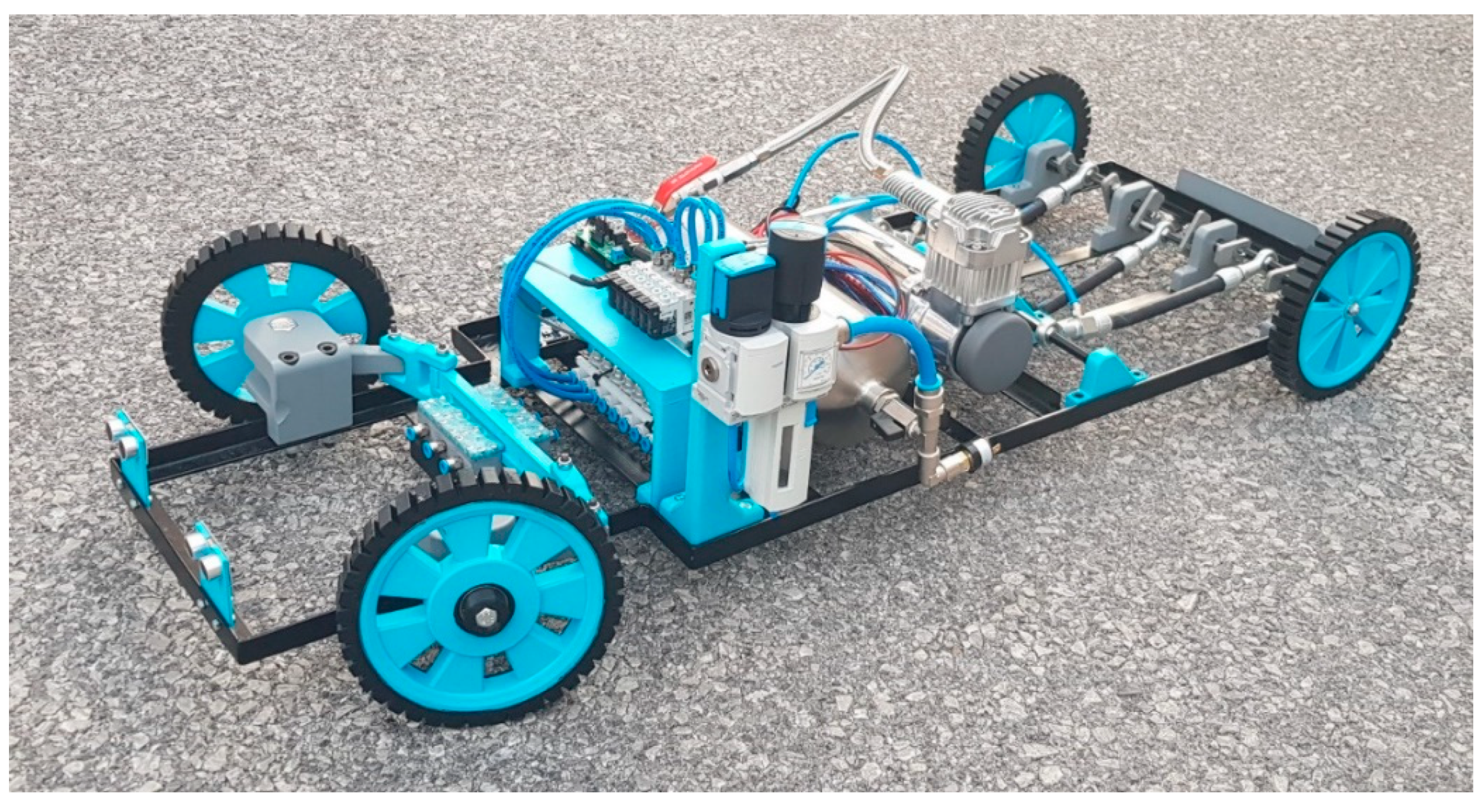
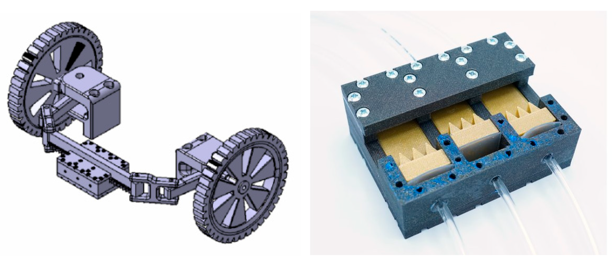
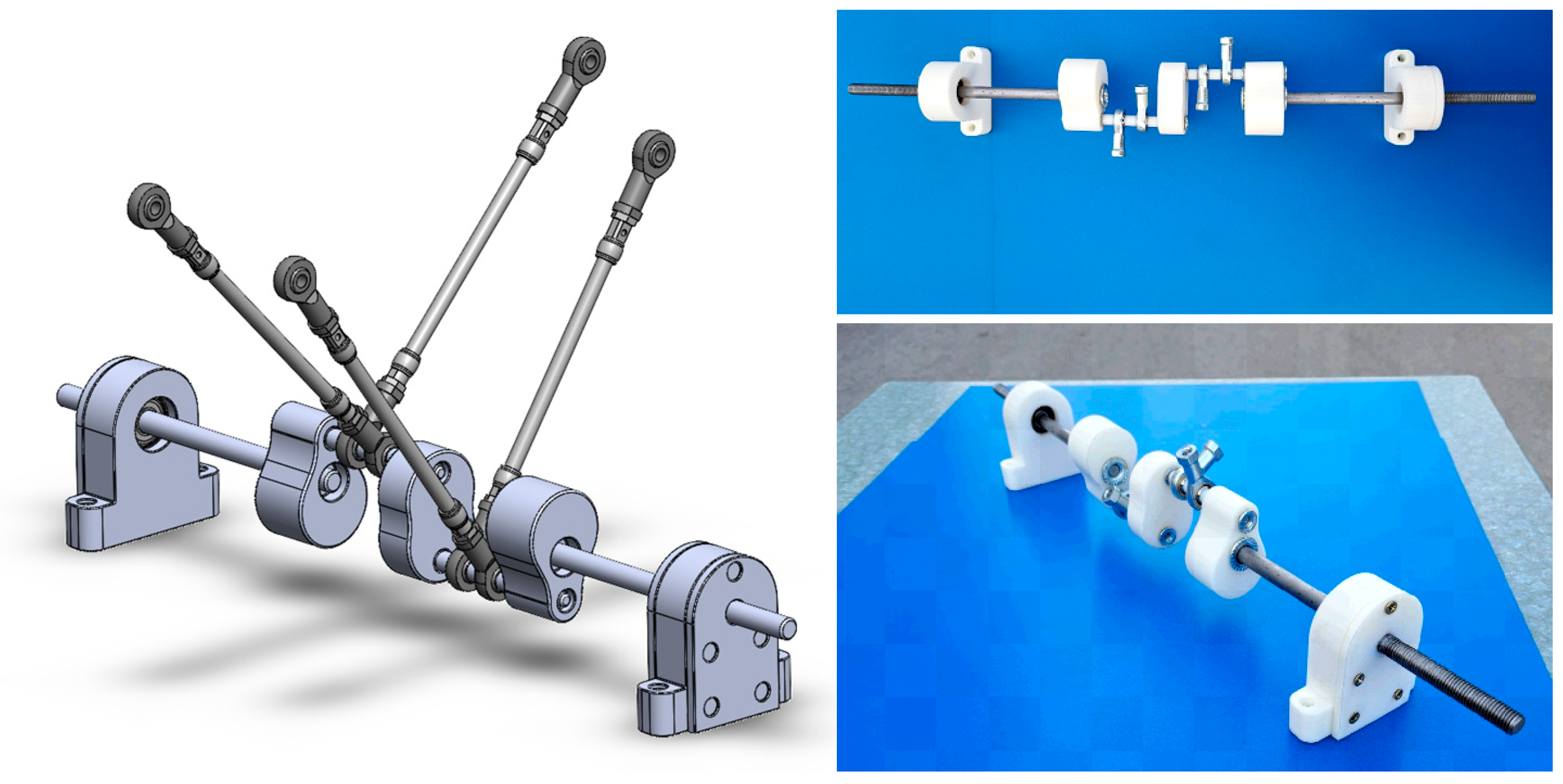
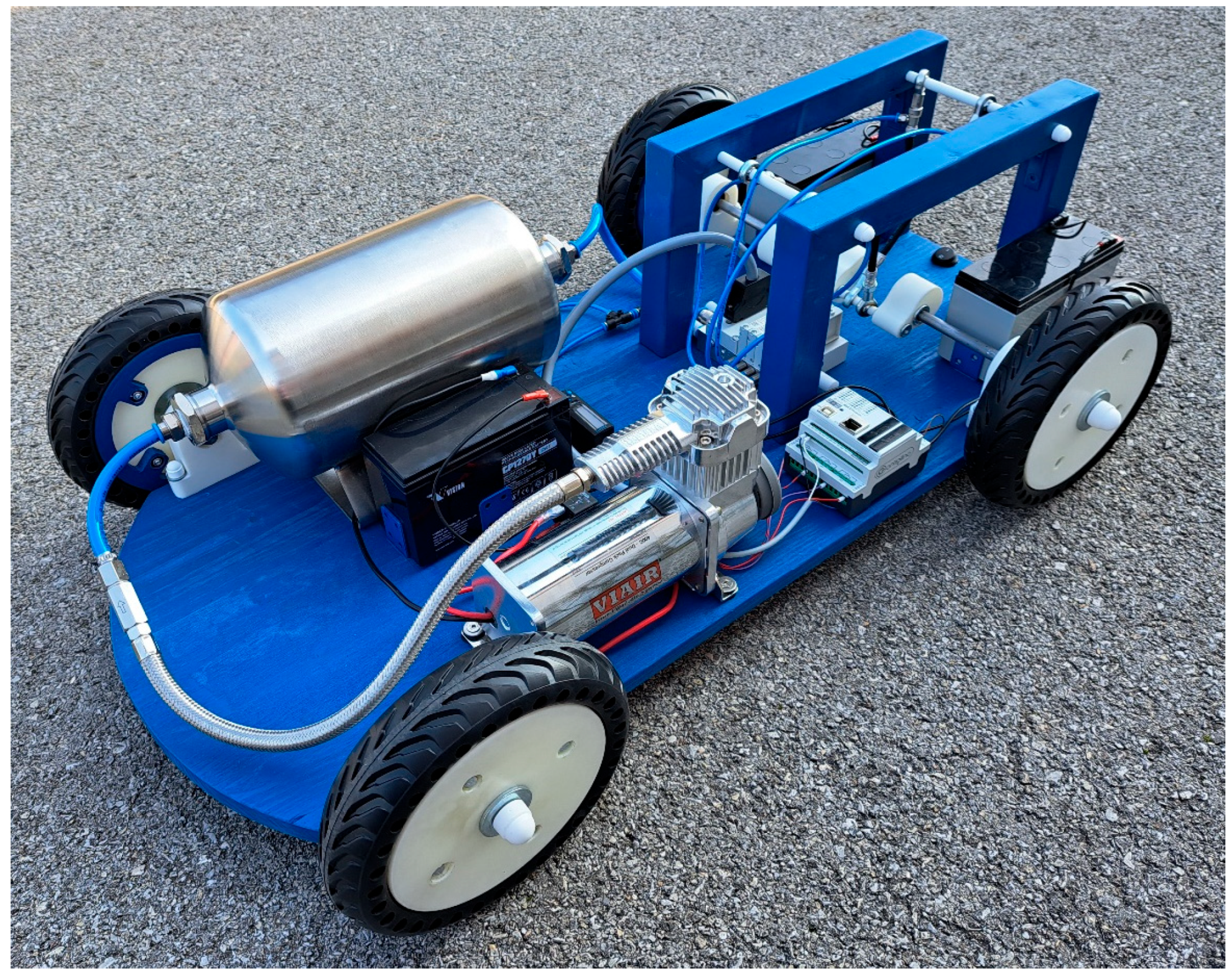
2.2. Autonomous Vehicles

Autonomous Vehicles Driven by PAMs

The integration of electronic devices has enabled the application of modern control techniques to pneumatic drive systems, thereby expanding their utility in robotics and mobile platforms. The development of autonomous mobile robots capable of operating in unstructured environments poses a significant engineering challenge, requiring advanced solutions in navigation, control, and propulsion. While electrification is commonly preferred due to its environmental advantages, alternative actuation methods such as PAMs present promising opportunities for the next generation of mobile robotic systems. A prototype of an autonomous vehicle actuated by PAMs is shown in Figure 4. The propulsion system employs a crankshaft mechanism that converts the linear pulling force generated by three pneumatic muscles into continuous rotational motion for the drive wheels. Each segment of the crankshaft is offset by 120° relative to the adjacent segment, thereby enabling complete rotation. The crankshaft is supported by four precision bearings to accommodate the unbalanced bending loads experienced during operation. The vehicle chassis and mechanical components are fabricated from stainless steel, machined using turning and milling processes to ensure structural integrity and mechanical precision [20]. This design exemplifies the feasibility of using fluidic muscles as an alternative propulsion method for autonomous mobile systems operating in demanding environments.
The chassis design prioritized structural strength and simplicity, employing an L-profile as the primary structural element. Fixing points were integrated at locations subjected to dynamic loads to ensure mechanical stability. The chassis dimensions are 1100 × 360 mm, and the frame was fabricated through welding. The mechanical subsystems, including the drive shaft and steering mechanism, were carefully engineered for robustness and functionality. Steering is accomplished using a pneumatic linear stepper motor controlled by a microcontroller.
The mechanism employs a rack-and-pinion configuration to achieve differential rotation between the inner and outer wheels, as illustrated in Figure 5. The linear stepper motor, fabricated using 3D printing technology, features a metal-free design. It utilizes a toothed rack actuated by three-phase pneumatic pistons, allowing for 1/3-step incremental movements to control wheel orientation with high precision.
The vehicle is powered by two independent electrical sources. The first power source, dedicated to operating the air compressor, delivers 12 V with a maximum current capacity of 300 A. The second source, a 22.2 V rechargeable battery with a capacity of 3000 mAh, supplies the valve block. An Arduino-based microcontroller governs the vehicle’s control logic and autonomous driving functionality. Airflow into the pneumatic drive system is regulated via MOSFET transistors, and power status is visually indicated using LED indicators. Compressed air is stored in a reservoir, and pressure levels are continuously monitored. When the tank pressure falls below 5 bar, a pressure switch is triggered. The microcontroller then activates the solenoid valves, allowing compressed air to flow into the pneumatic muscles and drive the vehicle (see attached video S3).
This section also presents an alternative model of an autonomous vehicle powered by pneumatic artificial muscles (PAMs). The vehicle employs a crankshaft-based drive system actuated by four PAMs arranged in a V-shaped configuration. The system was initially designed with three actuators; however, this configuration was unable to achieve a complete crankshaft rotation due to insufficient contraction force. To resolve this limitation, a fourth actuator was incorporated into the design. The revised configuration places two PAMs on each side of the V-shape, mounted with a 180° phase offset on the crankshaft. This arrangement corresponds to the angular spacing between the eccentrics of the first and second hinges, ensuring balanced force transmission and continuous crankshaft motion. The overall crankshaft design resembles those commonly employed in conventional motorcycle engines, offering mechanical robustness and efficient energy transfer through cyclic motion.
The pneumatic muscles are mounted at an angle of 45° relative to the vertical (radial) axis of the crankshaft, as illustrated in Figure 6. The muscles are arranged in a 1–4–3–2 sequence, oriented perpendicularly to the shaft axis. This configuration, combined with a 180° phase offset between opposing actuators, enables sequential activation for each 90° rotation of the crankshaft, thereby ensuring continuous and smooth rotational motion. The fully assembled autonomous vehicle, equipped with the pneumatic muscle-based engine, is depicted in Figure 7.

2.3. Mechatronic Systems

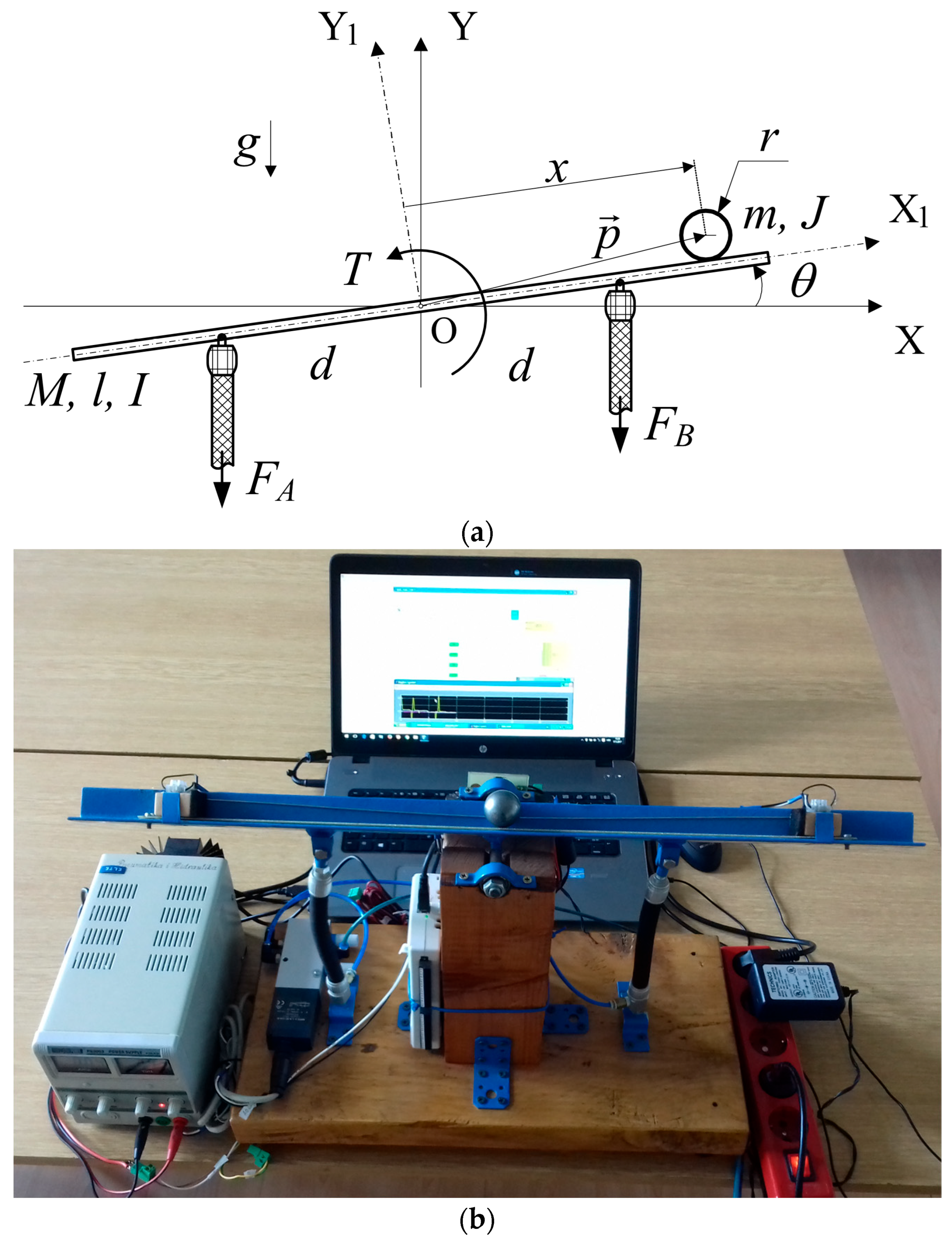
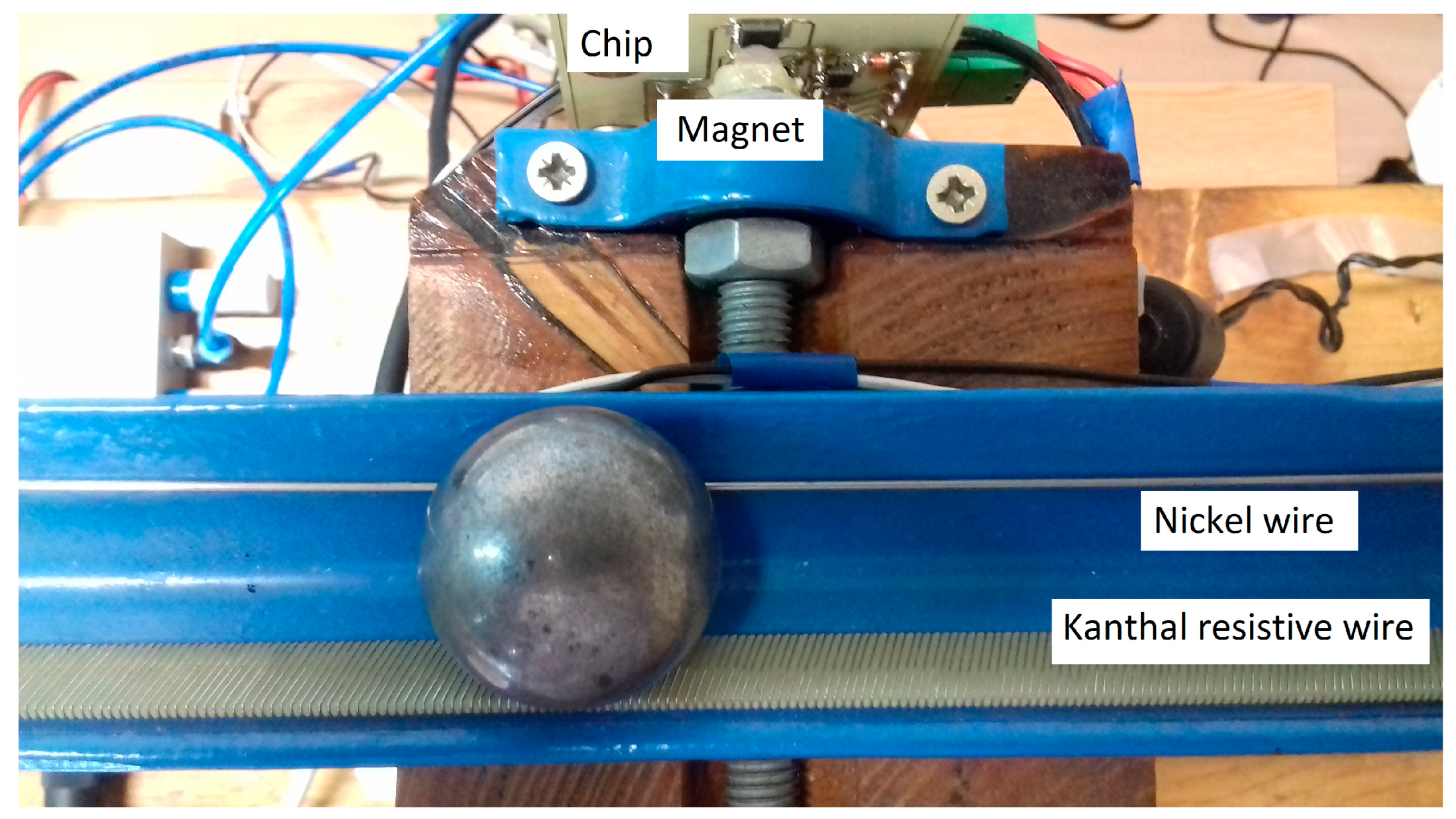
2.3.1. Ball on Beam Balancing Mechanism Actuated by PAMs

The ball-and-beam system is a well-established benchmark for evaluating advanced control strategies, owing to the complexity of its design and dynamic behavior. Like inverted pendulum or inverted wedge systems, it serves as a platform for implementing and testing a variety of nonlinear control techniques, including feedback stabilization, variable structure control, passivity-based control, backstepping and forwarding methods, nonlinear observers, friction compensation, and others [21,22,23]. This system provides a representative model for addressing the stabilization challenges inherent to dynamically unstable systems in control engineering. In the experimental configuration described here, PAMs are employed to actuate the beam rotation required for balancing. However, the compressibility of air and the nonlinear relationship between force and contraction in PAMs introduce additional complexity to the control task. The experimental setup is composed of two main subsystems: a mechanical section that includes the ball-and-beam mechanism, pneumatic valves, and sensors; and a control section that incorporates a computer and data acquisition system for signal processing and control computation. Figure 8 illustrates the ball-and-beam apparatus actuated by PAMs.
Antagonistic pneumatic muscles (Festo DMSP-10-150N-RM-CM) (Festo, Esslingen, Germany) are employed to actuate a revolute joint, enabling vertical rotation of a V-shaped steel beam mounted on bearings fixed to a wooden support structure. The rotational motion is controlled by modulating the pressure differential between the two opposing muscles. A proportional control valve regulates the flow of pressurized air to the muscles, with a control signal operating in the voltage range of 0 to 10 V. At 5 V, the valve remains closed, preventing airflow into the PAMs and resulting in zero pulling force. Stabilization of the ball is achieved through a digital control algorithm implemented on a dedicated control computer. Process signals are transmitted via a data acquisition card (NI USB-6212) (National Instruments, Austin, TX, USA), featuring 16-bit analog-to-digital and digital-to-analog converters. The control software is developed within the MATLAB/Simulink (version R2018b) environment and compiled into ANSI C code using the Real-Time Workshop (RTW) tool, allowing real-time execution. The ball position is measured using a custom sliding potentiometer system, in which a metal ball serves as the moving contact. The position sensor consists of a canthal resistive wire (a ferritic iron-chromium-aluminum alloy) wound around a vitroplast board. As the beam tilts, gravitational force causes the ball to roll along its surface, contacting the resistive wire and thereby closing the electrical circuit at varying positions along the track (see attached video S4). The beam angle is measured using a 12-bit contactless magnetic rotary position sensor (AMS AS5045) (AMS, Knoxville, TN, USA). This sensor integrates Hall-effect elements, an analog front end, and digital signal processing into a single system-on-chip (SoC). A neodymium magnet is affixed to the beam shaft and positioned directly above the sensor to enable precise angle measurement. Figure 9 illustrates the measuring systems for both ball position and beam angle [24].

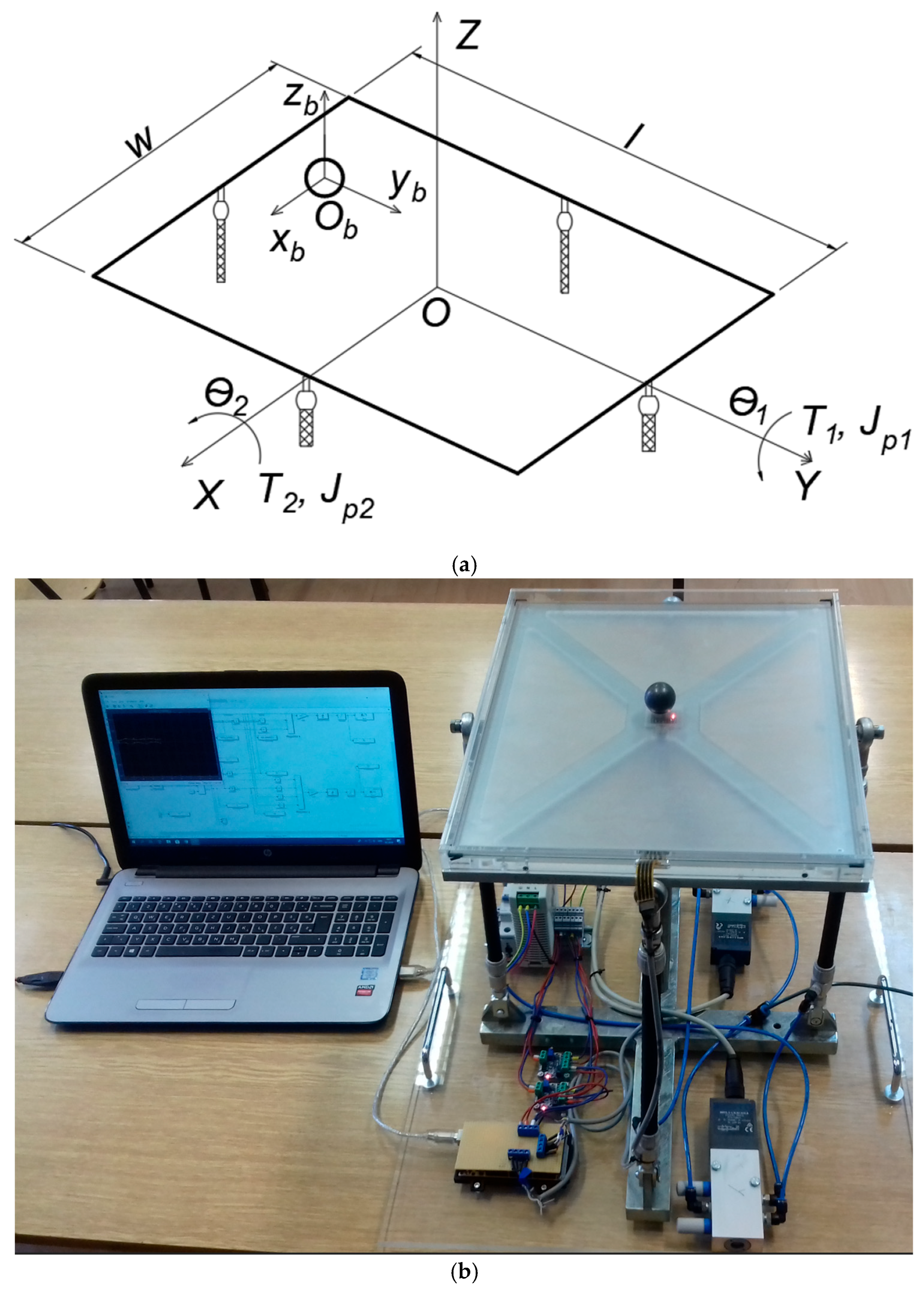
2.3.2. Ball on Plate Balancing Mechanism Actuated by PAMs

The ball-and-plate system extends the classical two-degree-of-freedom (2DOF) ball-and-beam configuration to a four-degree-of-freedom (4DOF) system. It serves as a standard benchmark in control theory due to its nonlinear, multivariable, underactuated, and open-loop unstable dynamics. The control objectives for this system include both point stabilization and trajectory tracking. The experimental platform, shown in Figure 10, is designed to investigate advanced control methodologies in the context of pneumatic actuation systems. In the experimental setup, a steel ball is placed on a 17-inch resistive touchscreen panel equipped with a four-wire analog input interface. The ball’s position is determined by measuring voltage drops (0–5 V) along the X and Y axes. These measurements are processed by an Arduino Mega 2560 microcontroller (Microchip Technology Inc., Chandler, AZ, USA). A key limitation of the resistive touchscreen is its inability to simultaneously detect both coordinates. The X and Y positions are sampled sequentially with a 1-microsecond delay to address this constraint, allowing sufficient time for voltage stabilization along the alternate axis. The touchscreen is mounted on a transparent plexiglass plate, which is securely fastened to a precision-machined aluminum frame. Angular velocity measurements are obtained using an MPU-6050 inertial measurement unit (IMU), which is centrally mounted within the aluminum frame. This IMU integrates a three-axis gyroscope and a three-axis accelerometer into a single chip and offers four programmable measurement ranges for angular velocity in degrees per second. It also includes a configurable digital low-pass filter. Communication between the IMU and the microcontroller is achieved using the I²C protocol. To enable actuation, two pairs of antagonistically arranged PAMs (Festo DMSP-10-200N-RM-CM) (Festo, Esslingen, Germany) are employed to rotate the platform about a central spherical joint. This configuration allows precise control of the platform’s inclination in both axes, enabling real-time stabilization and trajectory tracking of the ball (see attached video S5).
The torque required to rotate the plate along the X and Y axes is generated through the contraction of PAMs. Muscle contraction is regulated using two proportional 5/3-way control valves (Festo MPYE-5-1/8 HF-010B) (Festo, Esslingen, Germany), each controlled by a voltage signal ranging from 0 to 10 V. The applied control signal adjusts the airflow rate, thereby inducing a pressure differential across the antagonistically arranged PAMs and resulting in controlled contraction. An Arduino microcontroller is used to generate the control signals in the form of pulse-width modulation (PWM) within a 0 to 5 VDC range. Two voltage converters are employed to match the 0–10 V input requirement of the proportional valves. The initial PWM signal is set to 2.5 V, which, after conversion, corresponds to 5 V at the valve input, centering the valve spool and ensuring equal flow to both muscles, thus maintaining a neutral position. The controller is developed in the MATLAB/Simulink environment on a personal computer. It utilizes custom-built Simulink blocks for touchscreen data acquisition, a dedicated library for sensor integration, and the Simulink Support Package for Arduino hardware interfacing. Controller performance is evaluated under three distinct test scenarios: (1) stabilization of the ball at the center of the plate, (2) tracking of a circular trajectory, and (3) tracking of a square trajectory. These tests are designed to assess the system’s stability, responsiveness, and precision in executing complex motion profiles.

2.4. Orthopaedic Devices

PAMs are increasingly utilized in musculoskeletal rehabilitation, particularly for elderly individuals or patients recovering from injury. These actuators are commonly integrated into powered orthotic devices to assist and restore functional movement. Ankle-foot orthoses (AFOs) are typically classified as either passive or active. Passive AFOs rely on spring-based mechanisms fabricated from various materials to support the patient’s gait. In contrast, active AFOs employ powered actuators to generate the necessary force for lifting the foot into the correct position, thereby facilitating a more natural walking pattern [25,26,27]. The following section describes a prototype of an active ankle-foot orthosis developed in our laboratory.

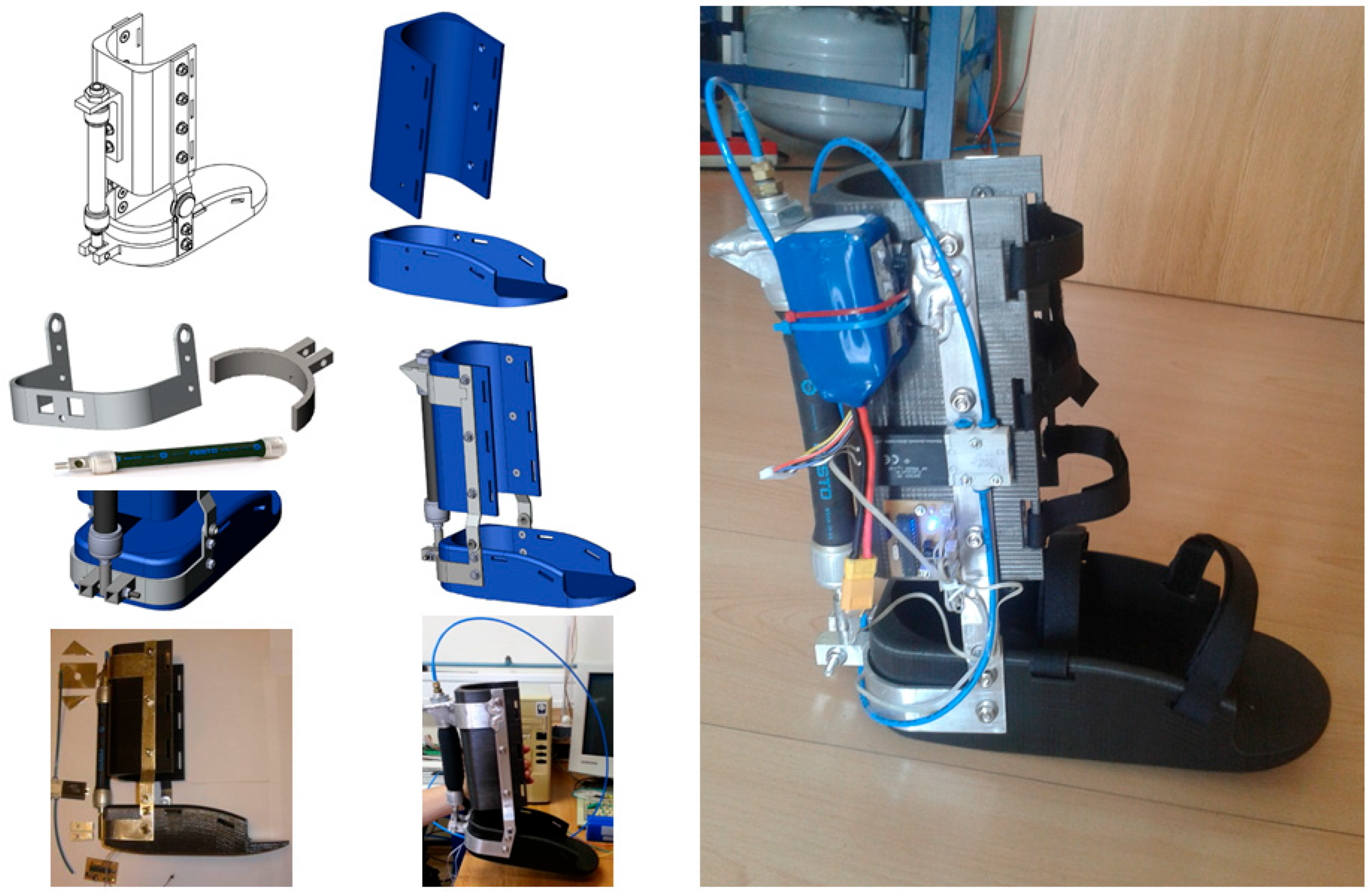
Active Ankle-Foot Orthotic Device Actuated by PAM

Figure 11 illustrates an active ankle-foot orthosis powered by pneumatic actuation, designed to assist individuals affected by foot drop, a condition characterized by the inability to lift the forefoot independently while walking. This orthosis aids in restoring the foot to its natural position, thereby improving the user’s gait and overall walking stability. Actuation is achieved using a pneumatic muscle (Festo DMSP-20-150N-AM-CM) (Festo, Esslingen, Germany), which is controlled by a solenoid valve (Festo MHE2-MS1H-3/2G-QS-4-K). A preliminary design of the orthosis was created in SolidWorks (SOLIDWORKS Dassault Systemes, Paris, France, ver. 2018), followed by fabrication using PLA plastic via 3D printing to minimize weight. Hollow sections were integrated into the printed components to further reduce mass, while connecting elements were constructed from aluminum. The device is designed to be securely fastened to the patient’s lower leg using adjustable strap belts. The control system is based on an ATmega328 microcontroller (Microchip Technology Inc., Chandler, AZ, USA). Two micro-switches are installed beneath the heel and toes, respectively. When the first switch (under the heel) is activated, a timing sequence begins. Upon receiving a subsequent signal from the second switch (under the toes), the microcontroller stops the timer and activates the solenoid valve after a delay equal to the interval between the two signals. This approach allows the user to control walking rhythm, thereby enhancing balance and facilitating adaptation to the orthosis. Valve activation requires a 24 V signal, which is supplied via a voltage regulator implemented with a ULN2803A Darlington driver (STMicroelectronics, Geneva, Switzerland). This configuration regulates air pressure in the PAM to produce the necessary contraction force for dorsiflexion, lifting the foot for the subsequent step (see attached video S6). For portability, the system is supplied by an external compressed air source carried by the user in a backpack. The orthosis is designed for ease of use, comfort, and safety. It is lightweight, combining PLA plastic and aluminum components for structural strength, durability, and low mass. Plastic parts were manufactured additively with internal cavities, while metal elements were fabricated mechanically. The complete system weighs 1.45 kg and includes all essential subsystems. The device provides effective assistance during gait by supporting foot dorsiflexion, thereby improving stability for individuals with foot drop. However, it is intended solely as a mobility aid rather than a rehabilitation device. A notable limitation is its reliance on a backpack-mounted compressed air source, which constrains usage time depending on the available pressure and energy reserves.
To further confirm the effectiveness of the active ankle-foot orthosis, we conducted preliminary experiments with healthy users simulating foot drop gait patterns. These tests evaluated the device’s responsiveness during different gait phases, focusing on the timing accuracy of pneumatic muscle actuation and its effect on walking stability and foot clearance during the swing phase. Qualitative observations indicated improved dorsiflexion support, contributing to a smoother and more stable gait cycle. Although these initial trials were limited in scope, they demonstrated the orthosis’s ability to assist dorsiflexion effectively and enhance gait stability. This preliminary validation supports the practical functionality of the device in aiding foot drop gait.

3. Discussion and Results

The rapid advancement of digital technologies, including the Internet of Things (IoT), visual systems, 5G networks, and artificial intelligence, has revitalized interest in pneumatic systems. Although often perceived as traditional, PAMs present several advantages, such as a high power-to-weight ratio, inherent mechanical compliance, and structurally simple construction. However, practical limitations remain, including nonlinear behavior, delayed response due to air compressibility, and dependence on external compressed air sources [28,29]. The experimental systems presented in this study, comprising mobile robots, robotic manipulators, balance platforms, and orthotic devices, demonstrate the flexibility and viability of PAM-based actuation in both research and educational contexts. A variety of sensors and control strategies were employed, including PID control, proportional valves, and implementations developed in the MATLAB/Simulink environment. Systems such as the ball-on-beam and ball-on-plate platforms exemplify complex nonlinear dynamics and offer robust platforms for evaluating advanced control algorithms. In an educational setting, PAM-driven systems support project-based learning by bridging theoretical knowledge with practical application. This hands-on methodology fosters critical thinking and helps students understand system dynamics, control modeling, and the discrepancies between simulated models and real-world physical systems. Feedback from participants consistently emphasizes the pedagogical value of direct engagement with core concepts such as force, motion, and feedback control. Nonetheless, several challenges persist, particularly in mobile applications, such as ensuring a stable compressed air supply and maintaining reliable operation under varying environmental conditions. Despite these challenges, the systems developed in this work are modular, user-friendly, and easily upgradeable, making them suitable for ongoing research and educational development.
Contemporary educational methodologies increasingly emphasize experiential learning and interdisciplinary integration to enhance student engagement and conceptual understanding. Globally, educators recognize the importance of integrating classical and modern control theory with practical implementation and comparative analysis of various control strategies [30]. In the context of pneumatic muscle-powered systems, research demonstrates that incorporating project-based learning enables students to apply theoretical concepts to real-world problems, thereby enhancing problem-solving skills and fostering critical thinking. Such approaches can facilitate the development of educational kits that utilize PAMs in robotic arms or assistive devices, providing a tangible means for students to explore the principles of force, motion, and closed-loop control. Student feedback highlights the benefits of laboratory-oriented instruction, which includes hands-on interaction with electrical and pneumatic components, practical demonstrations of control systems, exploration of system modeling, and recognition of the deviations between theoretical predictions and physical system behavior. However, educational implementations of pneumatic systems face certain constraints, including the complexity of nonlinear control algorithms and the requirement for a consistent air supply in mobile configurations. The systems developed in this study address many of these issues by incorporating intuitive user interfaces and offering the potential for further improvement through component upgrades and sensor integration. Access to real-time feedback from integrated sensors enhances students’ understanding of dynamic system behavior. Prior to practical implementation, the development process includes a comprehensive literature review that surveys the current state of pneumatic muscle applications and their pedagogical utility. A detailed account of the design, construction, and evaluation methodology of each system is essential, along with a thorough analysis of encountered challenges and proposed directions for future research, particularly at the intersection of pneumatic technology and its broader industrial applicability.

4. Conclusions

This article presented a series of custom-built experimental systems powered by PAMs, developed as instructional platforms for teaching pneumatic actuation and feedback control within mechanical engineering curricula. PAMs have proven to be highly suitable actuators for innovative industrial applications, legged robotic systems, mechatronic devices, and biologically inspired assistive technologies. Using these pneumatically actuated experimental models, each exhibiting unique and intuitively understandable operating principles, students are introduced to essential engineering concepts, including mechanical system design, mathematical modeling of physical processes, parameter identification, simulation of nonlinear and linearized models, and the application of various control strategies. Experimental validation of these models further reinforces theoretical knowledge. This educational approach fosters a deeper understanding of fluid power systems and automatic control theory, highlighting their relevance and applicability across a broad range of engineering disciplines.

Supplementary Materials

The following supporting information can be downloaded at: https://www.mdpi.com/article/10.3390/inventions10040044/s1, Video S1: Walking robot actuated by PAMs; Video S2: Manipulator driven by PAMs; Video S3: Autonomous vehicle driven by PAMs; Video S4: Ball on beam system actuated by PAMs; Video S5: Ball on plate system actuated by PAMs; Video S6: Active ankle foot orthosis actuated by PAM.

Author Contributions

Conceptualization, Ž.Š. and J.B.; methodology, Ž.Š., M.C. and J.B.; software, Ž.Š. and J.B.; validation, Ž.Š. and J.B.; formal analysis, Ž.Š. and M.C.; investigation, Ž.Š., M.C. and J.B.; resources, Ž.Š.; data curation, J.B.; writing—original draft preparation, Ž.Š. and J.B.; writing—review and editing, Ž.Š. and M.C.; supervision, Ž.Š. and M.C.; project administration, J.B.; funding acquisition, Ž.Š. All authors have read and agreed to the published version of the manuscript.

Funding

This research was funded by the University of Zagreb, through tenders for short-term annual financial support for scientific research in the period 2018–2023.

Data Availability Statement

The data presented in this study are openly available in https://www.fsb.unizg.hr/?fsbonline&departments&library&lang=en (accessed on 10 June 2025); Repository of The Faculty of Mechanical Engineering and Naval Architecture University of Zagreb, https://repozitorij.fsb.unizg.hr/en (accessed on 10 June 2025).

Acknowledgments

We thank the companies Festo Croatia and SMC Croatia for the cooperation and sponsorship of pneumatic equipment necessary for the realization of experimental systems. We are most grateful to the students of the Faculty of Mechanical Engineering and Naval Architecture (Dominik Sremić, Hrvoje Brezak, Valentino Štahan, Vedran Tatalović, Viktor Mandić, Srečko Herceg, Šime Grbić, Filip Čavić, Petar Trslić, Tomislav Hodja, Marin Miletić, Hrvoje Selak, Andreas Šantek, and Denis Trivić) who participated in the creation of experimental systems during their graduation theses.

Conflicts of Interest

The authors acknowledge the companies Festo Croatia and SMC Croatia for the cooperation and sponsorship of pneumatic equipment necessary for the realization of experimental systems. The authors declare no conflicts of interest related to this acknowledgement or otherwise. The funders had no role in the design of the study; in the collection, analyses, or interpretation of data; in the writing of the manuscript; or in the decision to publish the results.

References

  1. Kalita, B.; Leonessa, A.; Dwivedy, S.K. A Review on the Development of Pneumatic Artificial Muscle Actuators: Force Model and Application. Actuators 2022, 11, 288. [Google Scholar] [CrossRef]
  2. Daerden, F.; Lefeber, D. Pneumatic Artificial Muscles: Actuators for robotics and automation. Eur. J. Mech. Environ. Eng. 2002, 47, 11–21. [Google Scholar]
  3. Jamil, B.; Oh, N.; Lee, J.-G.; Lee, H. A Review and Comparison of Linear Pneumatic Artificial Muscles. Int. J. Precis. Eng. Manuf.-Green Technol. 2024, 11, 277–289. [Google Scholar] [CrossRef]
  4. Palko, A.; Smrček, J. The use of pneumatic artificial muscles in robot construction. Ind. Robot 2011, 38, 11–19. [Google Scholar] [CrossRef]
  5. Caldwell, D.G.; Tsagarakis, N.; Medrano-Cerda, G.A. Bio-mimetic actuators: Polymeric pseudo muscular actuators and pneumatic muscle actuators for biological emulation. Mechatronics 2000, 10, 499–530. [Google Scholar] [CrossRef]
  6. Saito, M.; Miyazaki, Y.; Kato, Y.; Ohnishi, K. Position Control of a Double Air Chamber PAM Actuator Using a Sliding Mode Control with a Disturbance Observer. J. Robot. Mechatron. 2025, 37, 114–123. Available online: https://www.fujipress.jp/jrm/rb/robot003700010114/ (accessed on 15 May 2025). [CrossRef]
  7. Shen, Y.; Li, Y.; Zhang, T.; Zhu, J. Adaptive Control of Dual PAM Soft Actuators with Hysteresis Compensation Using Neural Networks. arXiv 2023, arXiv:2308.12088. [Google Scholar] [CrossRef]
  8. Hammond, F.L.; Shepherd, R.F.; Majidi, C. Trends in Bioinspired Soft Robotics: Advances in Actuation, Modeling, and Control. arXiv 2023, arXiv:2312.12312. [Google Scholar] [CrossRef]
  9. Ahn, K.K.; Nguyen, H.T.C. Intelligent switching control of a pneumatic muscle robot arm using learning vector quantization neural network. Mechatronics 2007, 17, 255–262. [Google Scholar] [CrossRef]
  10. Chang, M.-K.; Yen, P.-L.; Yuan, T.-H. Angle Control of a one-Dimension Pneumatic Muscle Arm using Self-Organizing Fuzzy Control. In Proceedings of the 2006 IEEE International Conference on Systems, Man and Cybernetics, Taipei, Taiwan, 8–11 October 2006. [Google Scholar]
  11. Xie, S.; Mei, J.; Liu, H.; Wang, Y. Hysteresis modeling and trajectory tracking control of the pneumatic muscle actuator using modified Prandtl–Ishlinskii model. Mech. Mach. Theory 2018, 120, 213–224. [Google Scholar] [CrossRef]
  12. Mhd Yusoff, M.A.; Mohd Faudzi, A.A.; Hassan Basri, M.S.; Rahmat, M.F.; Shapiai, M.I.; Mohamaddan, S. Switching Model Predictive Control for Thin McKibben Muscle Servo Actuator. Actuators 2022, 11, 233. [Google Scholar] [CrossRef]
  13. Hosoda, K.; Sakaguchi, Y.; Takayama, H.; Takuma, T. Pneumatic-driven jumping robot with anthropomorphic muscular skeleton structure. Auton. Robot. 2010, 28, 307–316. [Google Scholar] [CrossRef]
  14. Verrelst, B.; Vermeulen, J.; van Ham, R.; Lefeber, D. Control Architecture for the Pneumatically Actuated Dynamic Walking Biped ‘Lucy’. Mechatronics 2005, 15, 703–729. [Google Scholar] [CrossRef]
  15. Aschenbeck, K.S.; Kern, N.I.; Bachmann, R.J.; Quinn, R.D. Design of a Quadruped Robot Driven by Air Muscles. In Proceedings of the First IEEE/RAS-EMBS International Conference on Biomedical Robotics and Biomechatronics, Pisa, Italy, 20–22 February 2006; pp. 875–880. [Google Scholar]
  16. Li, Q.; Cicirelli, F.; Vinci, A.; Guerrieri, A.; Qi, W.; Fortino, G. Quadruped Robots: Bridging Mechanical Design, Control, and Applications. Robotics 2025, 14, 57. [Google Scholar] [CrossRef]
  17. Chen, X.; Wang, L.Q.; Ye, X.F.; Wang, G.; Wang, H.L. Prototype development and gait planning of biologically inspired multi-legged crablike robot. Mechatronics 2013, 23, 429–444. [Google Scholar] [CrossRef]
  18. Shao, Q.; Dong, X.; Lin, Z.; Tang, C.; Sun, H.; Liu, X.-J. Untethered Robotic Millipede Driven by Low-Pressure Microfluidic Actuators for Multi-Terrain Exploration. IEEE Robot. Autom. Lett. 2022, 7, 12142–12149. [Google Scholar] [CrossRef]
  19. Šitum, Ž.; Herceg, S.; Bolf, N.; Ujević Andrijić, Ž. Design, Construction and Control of a Manipulator Driven by Pneumatic Artificial Muscles. Sensors 2023, 23, 776. [Google Scholar] [CrossRef]
  20. Šitum, Ž.; Benić, J.; Grbić, Š.; Vlahović, F.; Jelenić, D.; Kosor, T. Mechatronic systems with pneumatic drive. In Proceedings of the International Conference Fluid Power 2019, Maribor, Slovenia, 19–20 September 2019. [Google Scholar]
  21. Almutairi, N.B.; Zribi, M. On the sliding mode control of a ball on a beam system. Nonlinear Dyn. 2010, 59, 221–238. [Google Scholar] [CrossRef]
  22. Keshmiri, M.; Jahromi, A.F.; Mohebbi, A.; Amoozgar, M.H.; Xie, W.F. Modeling and control of ball and beam system using model based and non-model based control approaches. Int. J. Smart Sens. Intell. Syst. 2012, 5, 14–35. [Google Scholar] [CrossRef]
  23. Chang, Y.H.; Chan, W.S.; Chang, C.W. TS fuzzy model-based adaptive dynamic surface control for ball and beam system. IEEE Trans. Ind. Electron. 2013, 60, 2251–2263. [Google Scholar] [CrossRef]
  24. Šitum, Ž.; Trslić, P. Ball and Beam Balancing Mechanism Actuated With Pneumatic Artificial Muscles. ASME J. Mech. Robot. 2018, 10, 055001. [Google Scholar] [CrossRef]
  25. Alam, M.; Choudhury, I.A.; Mamat, A.B. Mechanism and Design Analysis of Articulated Ankle Foot Orthoses for Drop-Foot. Sci. World J. 2014, 2014, 867869. [Google Scholar] [CrossRef]
  26. Gordon, K.E.; Sawicki, G.S.; Ferris, D.P. Mechanical performance of artificial pneumatic muscles to power an ankle–foot orthosis. J. Biomech. 2006, 39, 1832–1841. [Google Scholar] [CrossRef] [PubMed]
  27. Shorter, K.A.; Xia, J.; Hsiao-Wecksler, E.T.; Durfee, W.K.; Kogler, G.F. Technologies for Powered Ankle-Foot Orthotic Systems: Possibilities and Challenges. IEEE/ASME Trans. Mechatron. 2013, 18, 337–347. [Google Scholar] [CrossRef]
  28. Scheidl, R.; Linjama, M.; Schmidt, S. Discussion: Is the future of fluid power digital? Proc. Inst. Mech. Eng. Part I J. Syst. Control. Eng. 2012, 226, 721–723. [Google Scholar] [CrossRef]
  29. Alt, R.; Malzahn, J.; Murrenhoff, H.; Schmitz, K. A Survey of Industrial Internet of Things in the Field of Fluid Power: Basic Concept and Requirements for Plug-and-Produce. Fluid Power Syst. Technol. 2018, 51968, V001T01A015. [Google Scholar] [CrossRef]
  30. Cox, D.J. Hands-on experiments in dynamic systems and control for applied education in robotics and automation. In Proceedings of the World Automation Congress, Waikoloa, HI, USA, 12–16 May 2008; pp. 1–6. [Google Scholar]
Figure 1. The construction process of WRAPAM and its final form.
Inventions 10 00044 g001
Figure 2. Manipulator arm actuated by PAMs, (a) schematic diagram, (b) photo.
Inventions 10 00044 g002
Figure 3. Measured signals during the manipulation of work items.
Inventions 10 00044 g003
Figure 4. Autonomous vehicle actuated by PAMs.
Inventions 10 00044 g004
Figure 5. Vehicle steering mechanism employing a pneumatic linear stepper motor.
Inventions 10 00044 g005
Figure 6. CAD model and assembly of the crankshaft.
Inventions 10 00044 g006
Figure 7. A vehicle with a pneumatic muscle engine.
Inventions 10 00044 g007
Figure 8. Ball on beam system actuated by PAMs, (a) schematic diagram, (b) photo.
Inventions 10 00044 g008
Figure 9. Ball position and beam angle measuring system.
Inventions 10 00044 g009
Figure 10. Ball on plate system actuated by PAMs, (a) schematic diagram, (b) photo.
Inventions 10 00044 g010
Figure 11. Active ankle foot orthosis actuated by PAM.
Inventions 10 00044 g011
Disclaimer/Publisher’s Note: The statements, opinions and data contained in all publications are solely those of the individual author(s) and contributor(s) and not of MDPI and/or the editor(s). MDPI and/or the editor(s) disclaim responsibility for any injury to people or property resulting from any ideas, methods, instructions or products referred to in the content.

