1. Introduction
Geotechnical engineering stands as a critical discipline at the intersection of construction, civil engineering, and earth sciences, addressing the challenges inherent in the interaction between soil and man-made structures [
1]. As urbanization continues to expand, so does the demand for infrastructure, driving the need for complex solutions to ensure the stability and safety of excavations, foundations, and slopes [
2,
3]. The foundation of any structure is only as strong as the ground upon which it rests. Geotechnical engineering plays a key role in assessing soil properties, understanding ground behavior, and devising strategies to mitigate risks associated with construction activities. Without a solid understanding of geotechnical principles, projects are vulnerable to many difficulties, including settlement, slope instability, and foundation failure, all of which can have catastrophic consequences on both human life and economic investments. Excavations, in particular, present unique challenges due to their intrusive nature and the potential impact on surrounding structures and the environment [
4,
5,
6,
7,
8,
9,
10,
11]. To address these challenges and ensure safe and cost-effective construction, the application of ground stabilization techniques has become increasingly essential.
Among these methods, soil nailing has gained prominence as an effective and versatile technique for addressing the stability of excavations. This technique involves reinforcing the ground by installing slender elements, typically steel bars or grouted rods, into the soil mass to improve its stability and resistance to deformation. Soil nailing offers several advantages over traditional support methods, including its versatility, cost effectiveness, and minimal disruption to adjacent properties [
12,
13]. By strategically placing soil nails along the excavation perimeter, engineers can effectively control ground movements, reduce excavation depths, and enhance overall stability. However, the success of soil nailing relies heavily on the proper design and placement of these reinforcement elements, taking into account factors such as soil properties, excavation geometry, and loading conditions.
The mechanical relationships at the soil–nail interface are established through the interaction of forces between the nails, grout, and surrounding soil. The primary mechanism is the shear resistance developed along the grout–soil interface, which is critical for maintaining stability and preventing soil deformation. The embedded steel nails transfer tensile forces from unstable soil layers to more stable ones, utilizing their axial stiffness and strength. The grout not only provides corrosion protection but also ensures effective load distribution from the soil to the nails through a strong bond. Optimized nail inclination, length, and spacing—together with their interaction with a shotcrete layer—are essential for ensuring stability and resistance to soil movement. This interdependence of material properties and geometric configuration underscores the importance of sound design in soil nailing applications.
It is crucial to prioritize the stability of the excavation wall and nearby buildings during the excavation process to mitigate potential financial and safety hazards. Various methods, including compaction, jet grouting, and soil mixing, can be employed based on project conditions such as land width, access, soil type, pit depth, and the significance of nearby structures. As explained, nailing is a commonly used method for stabilizing pits due to its fast execution and cost effectiveness [
14]. An optimal layout for this method should be determined to minimize costs while meeting design requirements, including permissible deformation and reliability factor. For the best layout, it is important to consider variables such as the angle of the nails in relation to the horizon, nail length, horizontal and vertical nail distances, and nail diameter [
15].
The soil nailing technique, developed approximately three decades ago, has become a reliable and widely used method for stabilizing earthen trenches and protecting pit walls. Its high flexibility and adaptability make it a preferred choice in geotechnical engineering. Soil nailing involves reinforcing the existing soil mass by installing threaded steel bars (nails) at close intervals along sloping or vertical excavation surfaces. The execution process typically proceeds from top to bottom, ensuring progressive stabilization.
Steel rebars are installed within boreholes drilled into the soil wall and grouted with cement slurry. The cement slurry not only facilitates efficient stress transfer between the soil and the nails but also protects the rebars from corrosion. This method offers several advantages, summarized as follows [
16]:
Enhances the shear strength of the soil mass.
Controls and limits horizontal displacement of the wall.
Reduces sliding forces on rupture and sliding surfaces.
Utilizes the existing soil for pit wall restraint, minimizing material usage.
Allows for additional nails if unexpected displacements occur.
Requires simple tools and materials, reducing complexity and costs.
Is suitable for retrofitting retaining structures.
Performs well against seismic forces due to its flexibility.
Is ideal for urban excavations, provided no heavy buildings are located near the pit.
Soil nailing can be implemented using one of the following two methods:
The wall or trench surface is first protected with mesh and shotcrete, followed by the installation of nails.
Nails are installed first, and the mesh and shotcrete are applied afterward to the wall or trench surface.
This technique offers a reliable and efficient approach to excavation stability, particularly in urban settings, where it ensures flexibility and adaptability under dynamic conditions such as seismic activity. However, it is less suitable for locations where heavy structures are adjacent to the excavation site due to potential displacements.
Numerous studies have been conducted on the topic of soil nailing. RJ Bridle [
17] explored the analysis and design of soil nailing structures, examining the methods used to analyze soil nailing, the implications of different design parameters, and the effects of various soil types on soil nail performance. Phear et al. [
18] provided guidance on best practices for soil nailing. Sharma and Ramkrishnan [
19] presented a parametric optimization and multi-regression analysis using numerical approaches. Moradi et al. [
20] investigated the effects of nail arrangement on the behavior of soil-nailed walls with convex corners through numerical analysis. Nowroozi et al. [
21] presented an optimum design approach using FLAC3D and demonstrated the behavior of nailed walls using finite difference methods. Bathini and Krishna [
13] provided an overview of various design aspects and examined influencing factors and limitations. Mohamed et al. [
22] examined finite element modeling parameters such as nail geometry, soil properties, and the interface between them.
Wei Xu et al. [
23] introduced an improved hybrid genetic algorithm to optimize soil nail parameters, addressing limitations of traditional methods such as local optima and slow convergence. Fadila Benayoun et al. [
24] used response surface methodology (RSM) to study the impact of nail length, inclination, and vertical spacing, identifying length and spacing as critical factors. Patra et al. [
25] applied nonlinear programming to optimize nail slope configurations, while Arvin et al. [
26] used the FHWA manual with numerical optimization to explore the effects of soil friction and slope geometry. Ramteke et al. [
27] found that a 15° inclination yielded the highest factor of safety. Kushwaha et al. [
28] highlighted the accuracy of numerical methods over conventional designs using Plaxis 2D, and Meen-Wah et al. [
29] simulated full-scale conditions, emphasizing nail depth and configuration effects.
Collectively, these studies reveal a trend toward advanced modeling and optimization approaches that focus primarily on individual design parameters. Yet, a common limitation lies in the lack of integrated analysis of multiple interacting variables and the limited exploration of economic or sustainability-related considerations.
To optimize the design and configuration of soil nails, engineers often turn to numerical modeling such as finite element analysis (FEA) for better understanding of ground behavior and structural response [
30,
31,
32,
33]. FEA allows for a detailed examination of complex interactions between soil, structure, and reinforcement elements, and it offers valuable information to guide design decisions and mitigate risks. In the context of excavation stability, FEA enables engineers to simulate various scenarios, assess the effectiveness of different reinforcement strategies, and evaluate the impact of key parameters such as nail length, orientation, and spacing [
34]. Plaxis software, which is based on numerical and finite element methods, is used in this study. Plaxis is employed by geotechnical engineers for most excavation analysis and design because it is user friendly and yields accurate results [
35,
36].
While all above-mentioned studies have advanced the understanding of soil nailing, several gaps remain. Much of the existing research focuses on isolated parameters such as nail length or angle without analyzing the combined influence of multiple variables on excavation stability. Additionally, limited attention has been paid to the role of soil properties, the economic and environmental sustainability of nail designs, or the evaluation of diminishing returns associated with increased nail length.
This study addresses these research gaps by performing a comprehensive parametric analysis using finite element modeling in Plaxis, considering nail length, inclination angle, spacing, and soil type simultaneously. A key contribution is the identification of interactions among these parameters and their collective impact on deformation control and factor of safety. Moreover, by incorporating the concept of sustainable infrastructure, the study aligns its optimization framework with the Sustainable Development Goals (SDGs), particularly focusing on efficient resource use and long-term ground stability.
The main objective of this study is to develop and validate an optimized soil nail design framework using finite element modeling (Plaxis) that integrates multiple parameters—nail length, inclination, spacing, diameter, and soil type—with the aim of enhancing excavation stability while minimizing material use and supporting sustainability goals.
The remainder of this paper is structured as follows.
Section 2 outlines the materials and methodologies employed, detailing the model geometry, meshing procedures, nail modeling techniques, shotcrete modeling approach, and the validation of model behavior.
Section 3 presents a comprehensive discussion and analysis of the principal findings. Subsequently,
Section 4 offers managerial implications derived from the study. Finally,
Section 5 concludes the paper by synthesizing the key insights and proposing potential avenues for future research.
4. Results and Discussion
This study proposes a parametric analysis approach to systematically evaluate and identify optimal configurations based on deformation and safety performance. So, it does not define a formal optimization problem with objective functions and constraints. Instead, future work may formulate the problem as a multi-objective optimization task.
In order to achieve results that are comparable with each other, one parameter should be considered as a variable in each of the analyses so that an accurate opinion can be expressed in that case. For a better understanding of the graphs,
Lavg and
Dn parameters are defined as follows:
where
Lavg is the total length of all nails divided by the number of nails (
n) used on the surface of the wall.
where
Dn represents the special density of nails on the surface of the wall and
Lh is the retaining wall width (length).
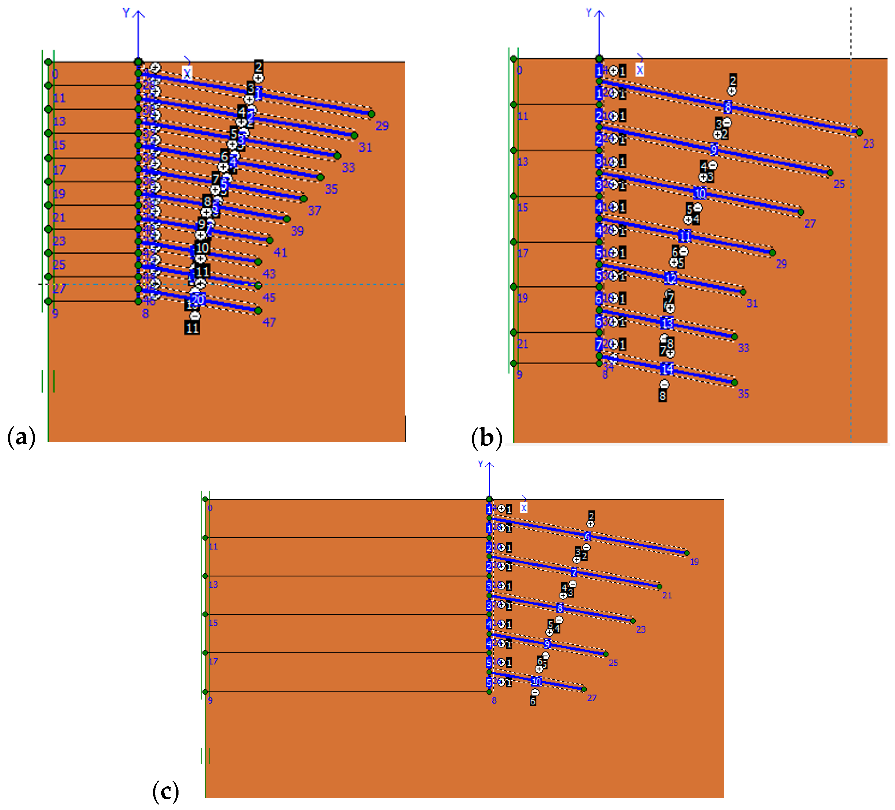
Changing the nailing arrangement.
The impact area of the nailing is the product of the horizontal distance multiplied by the vertical distance. FHWA regulations limit this area to four square meters (
Sv × Sh ≤ 4 m
2). Therefore, to check the accuracy of this issue, more distances have been tested, which have been examined quantitatively and qualitatively in
Figure 7 and
Figure 8 in terms of
Lavg and in
Figure 9 and
Figure 10 in terms of
Dn.
At first, the graphs are shown quantitatively in terms of L
avg and then analyzed qualitatively.
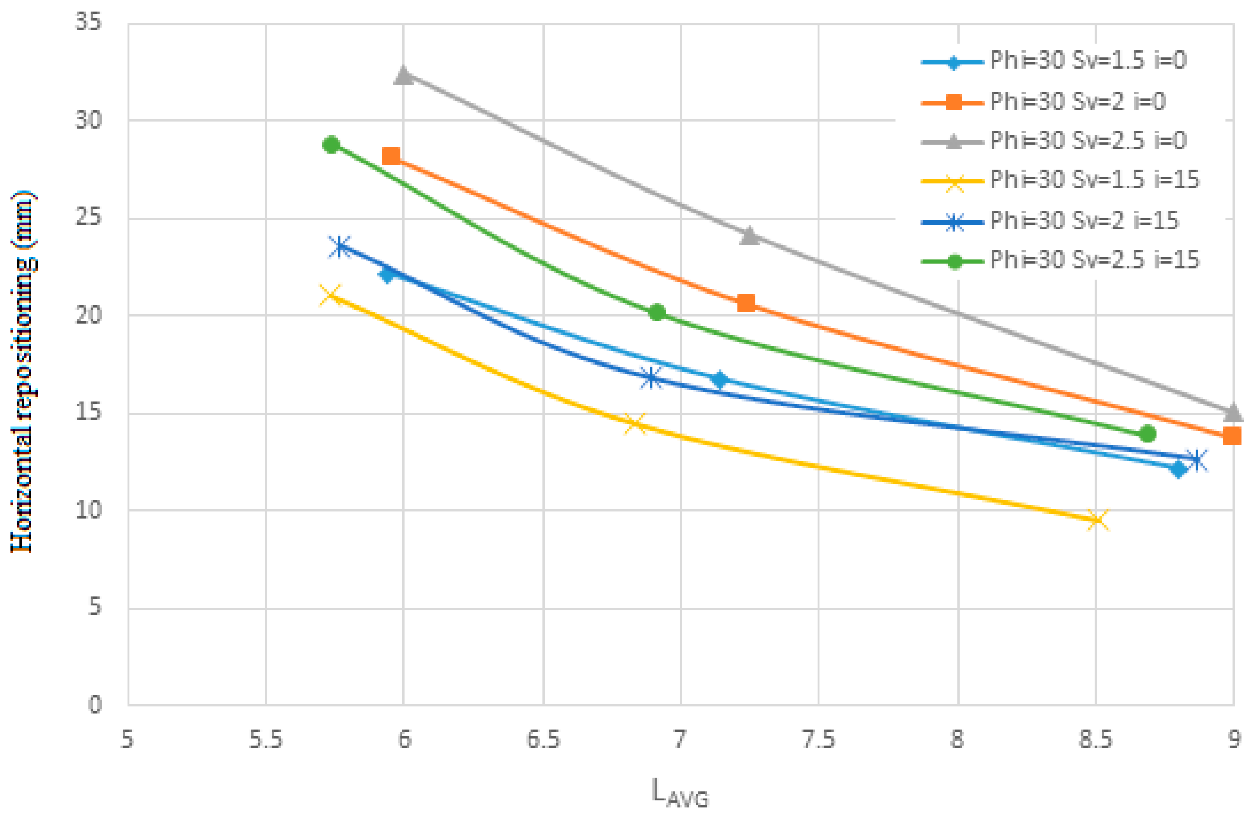
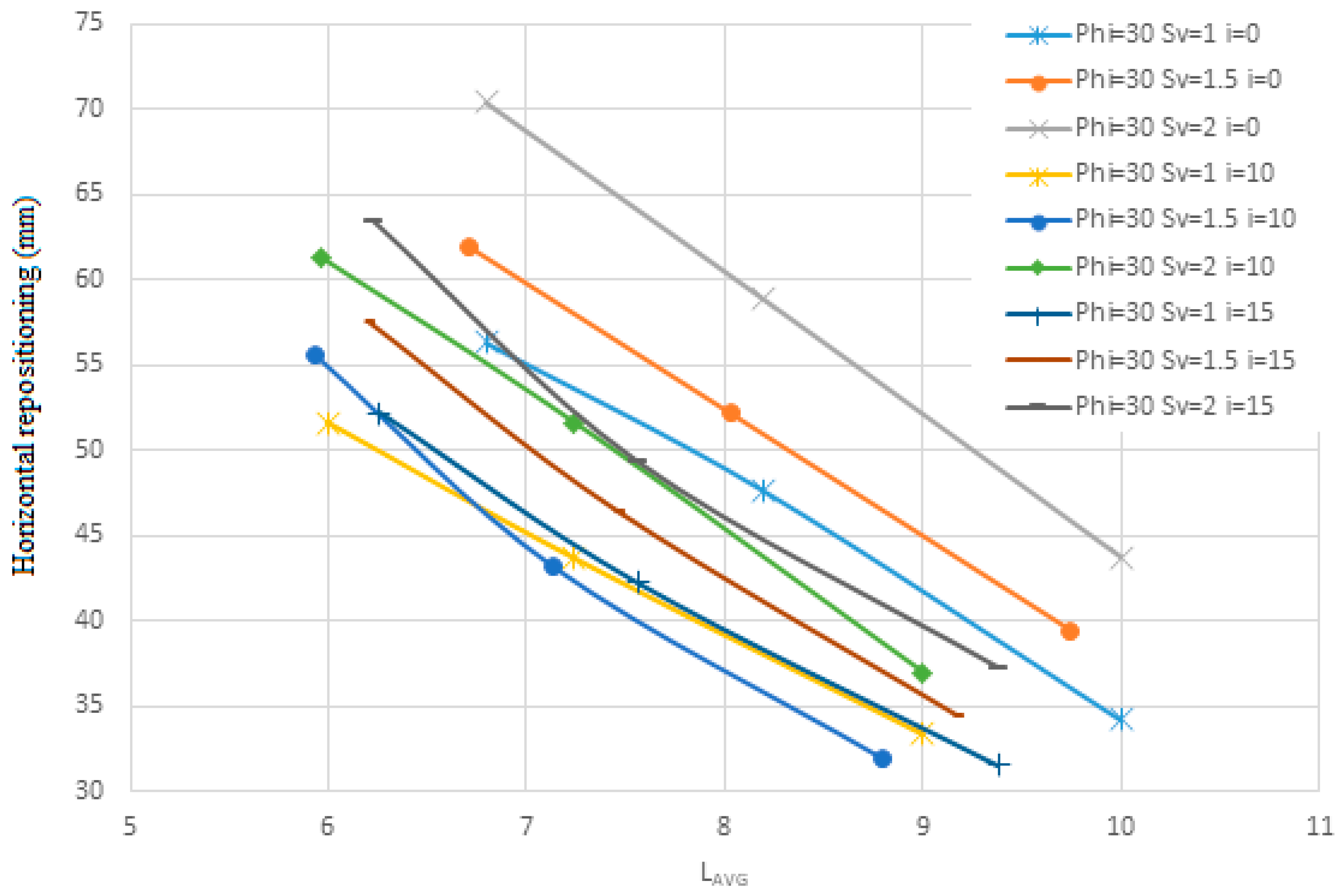
Figure 7 and
Figure 8 are drawn for the soil with an internal friction angle of 30 degrees and cohesion of 5 KN/m
2, and S
v changes from 1.5 to 2.5 m and the angle of the nails is 0 and 15 degrees and the diameter of the nails is 30 mm.
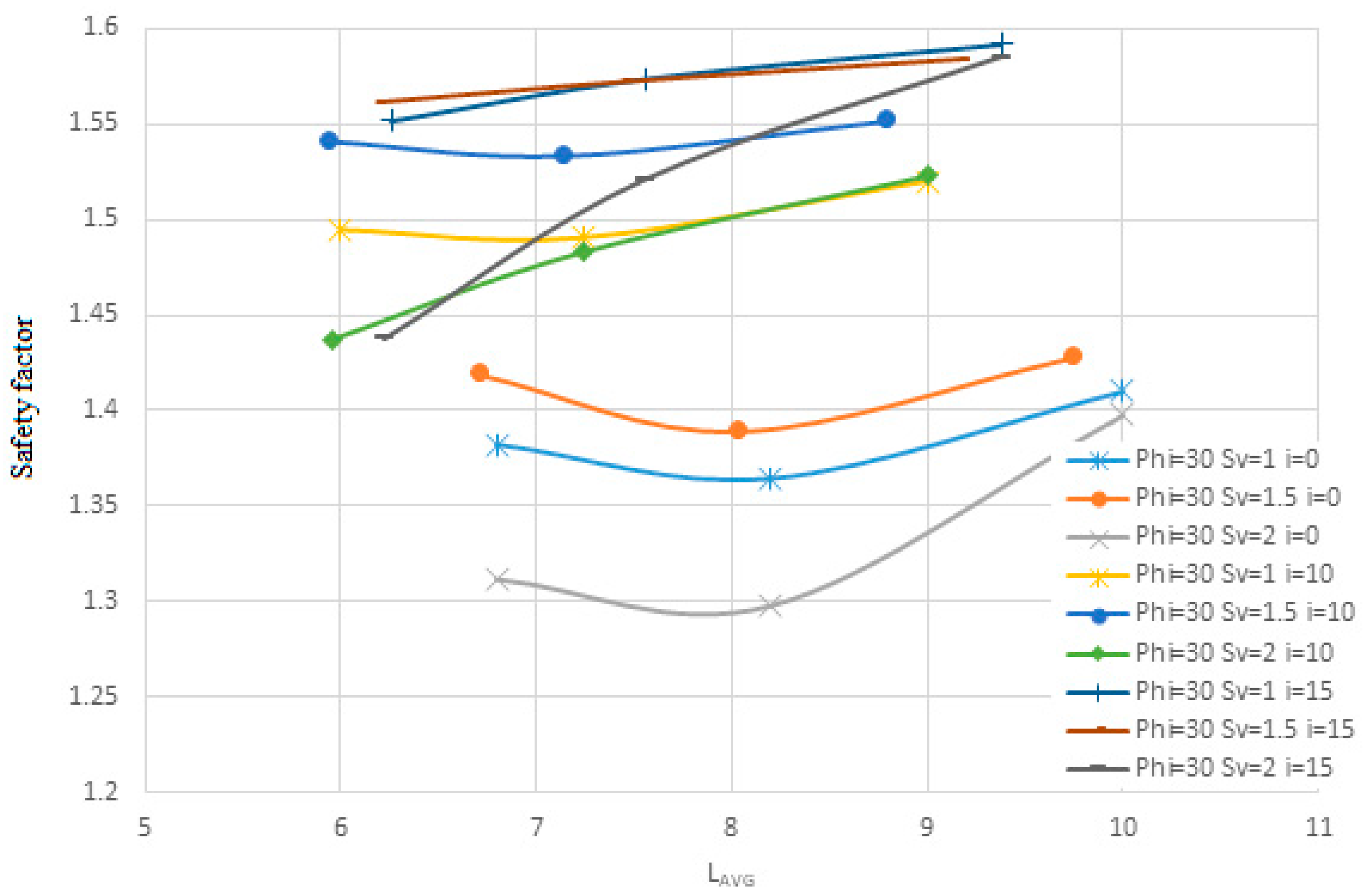
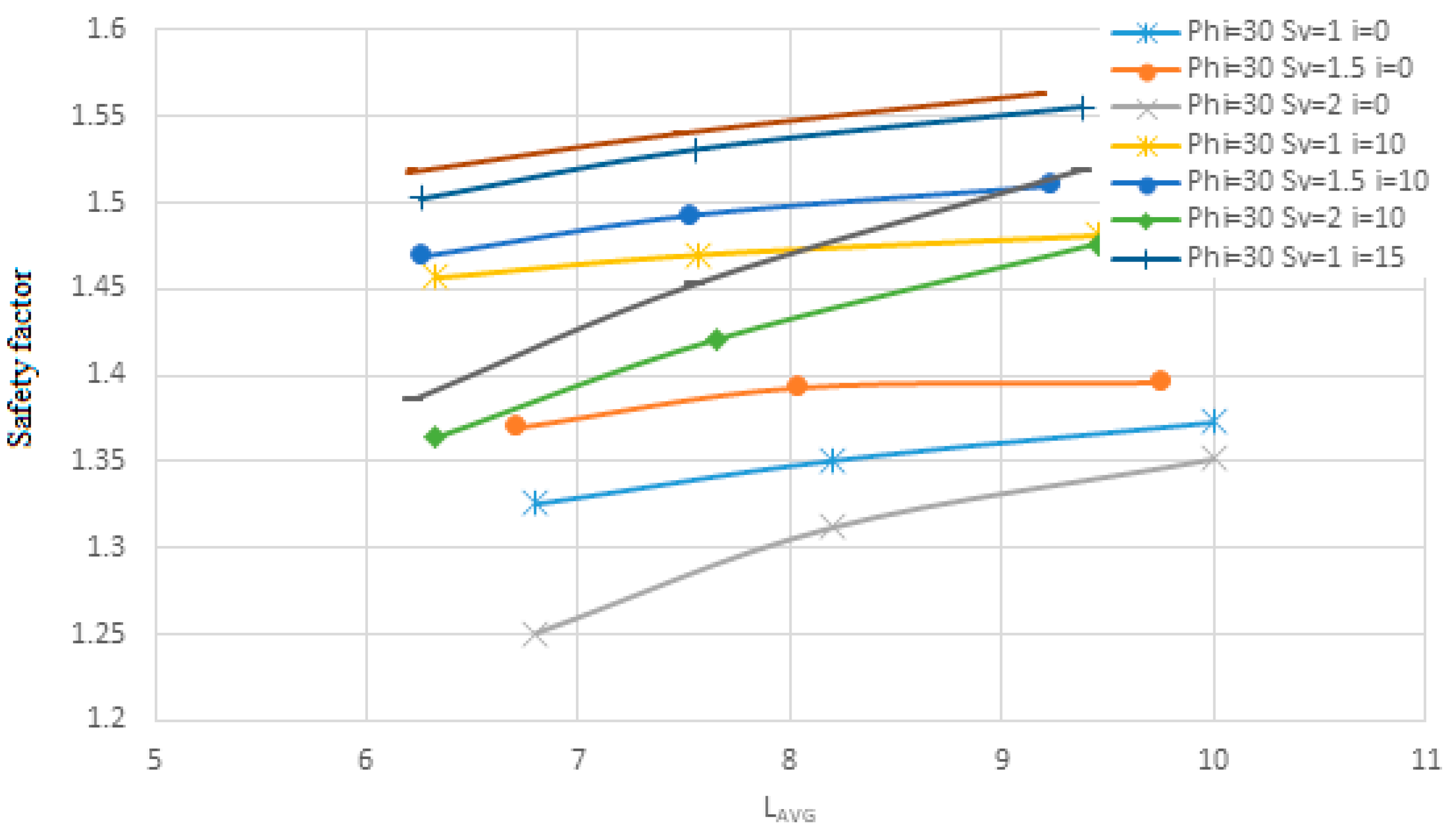
As shown in
Figure 7 and
Figure 8, as the average spacing between the piles (
Lavg) increases, the horizontal displacement decreases. This reduction follows a diminishing slope until the displacements between the piles converge and nearly stabilize at a constant value. Similarly, the allowable safety factor initially increases steeply with increasing pile spacing but eventually reaches a plateau where further changes become negligible.
Notably, when the pile spacing is 2.67 m, the pile angle is 0°, and the pile length is short, the allowable safety factor cannot be reliably estimated. This suggests that small pile lengths combined with low angles and large spacing, even if capable of predicting horizontal displacement, fail to estimate the allowable safety factor accurately.
Additionally, the results indicate that increasing pile length reduces horizontal displacement and enhances the allowable safety factor. However, this trend exhibits diminishing returns, with both displacement and safety factor stabilizing beyond a certain pile length. Therefore, it can be concluded that increasing pile length is effective only up to a specific threshold, beyond which further increases do not significantly impact the safety factor.
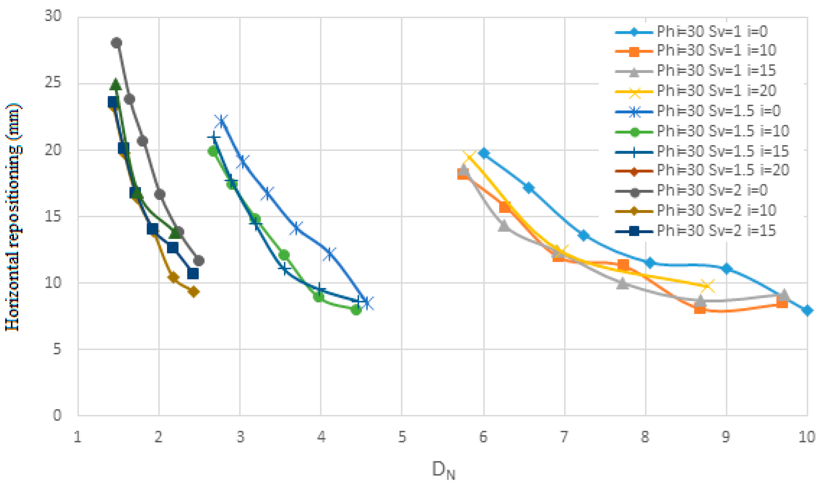
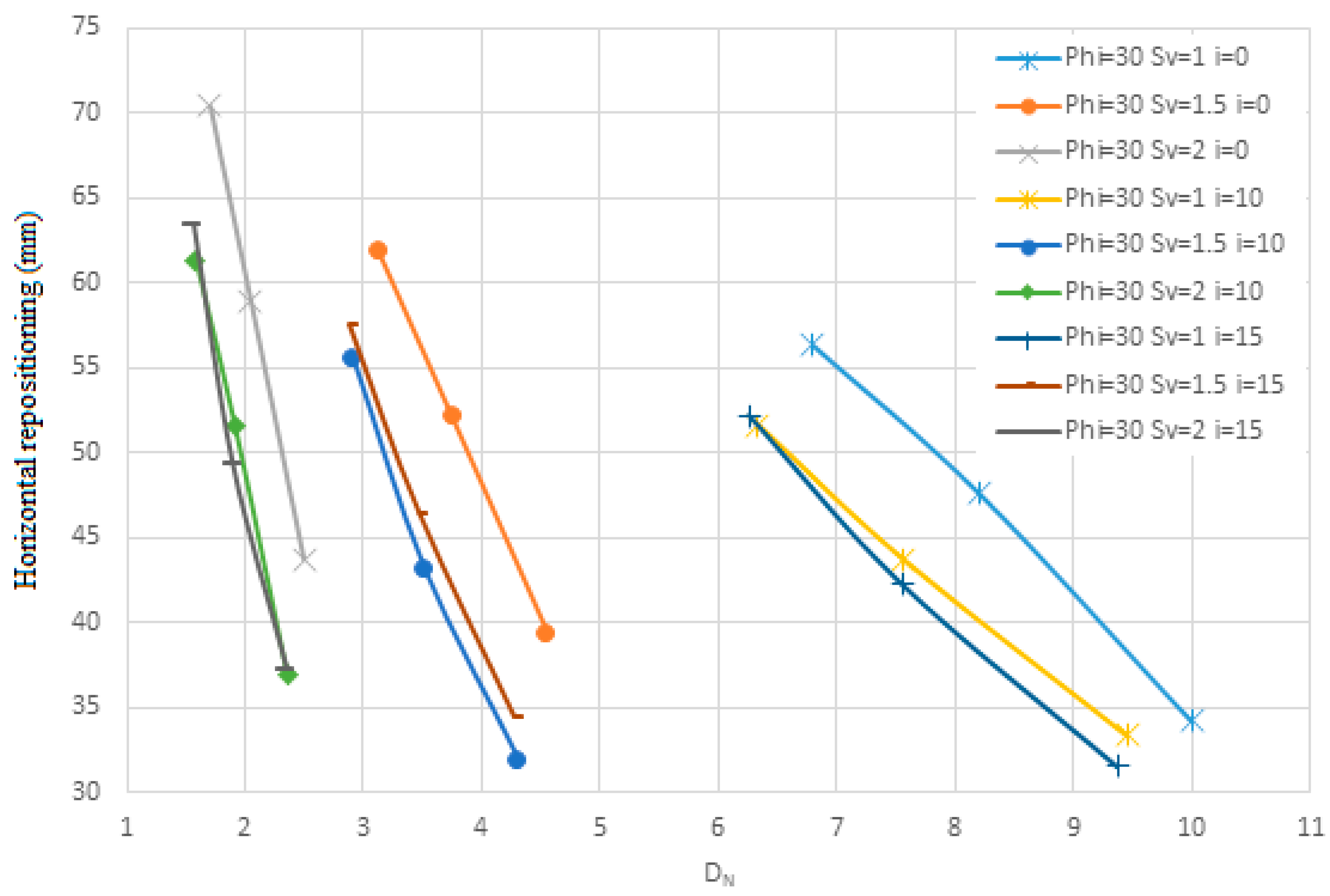
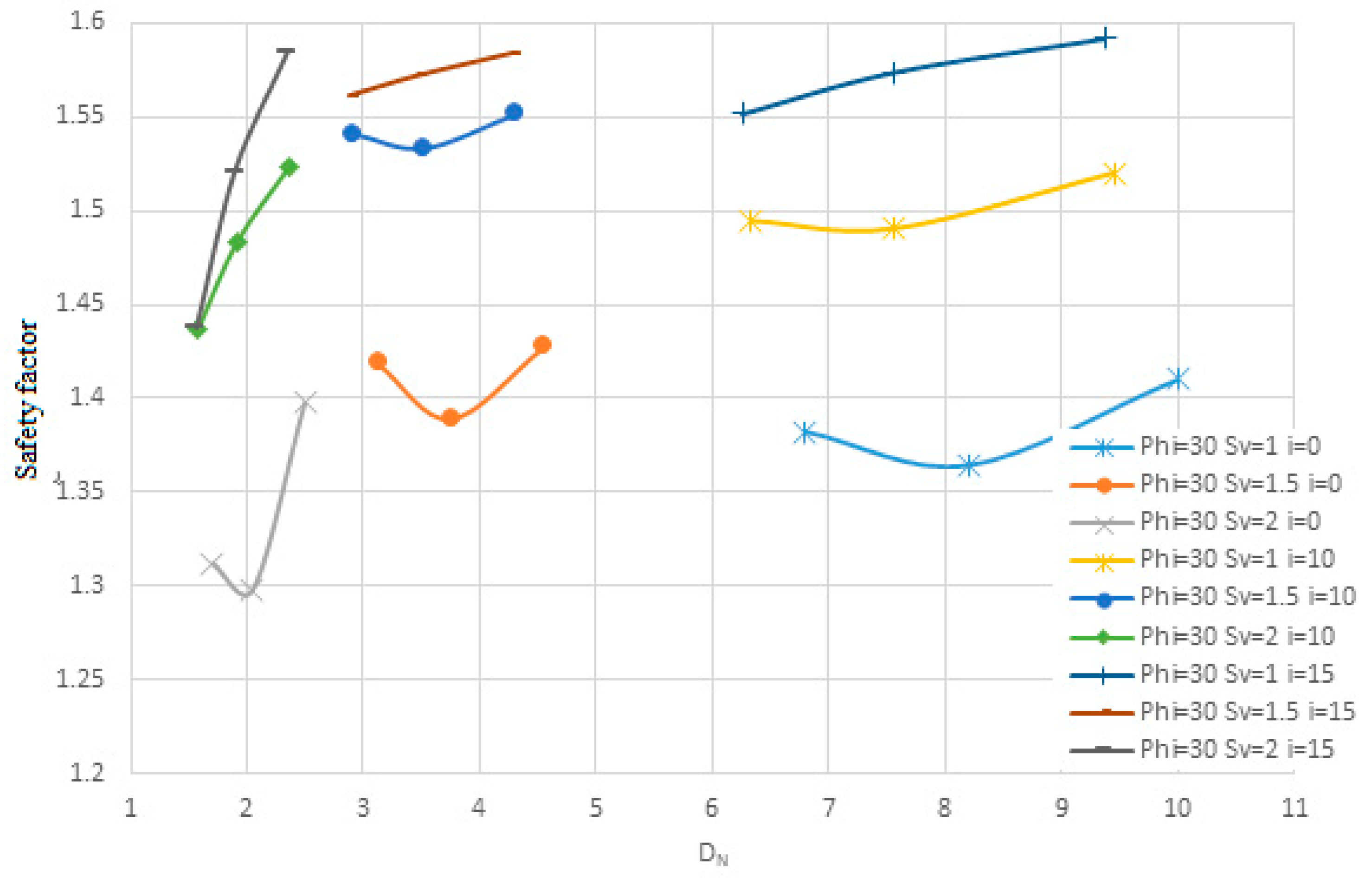
Figure 9 and
Figure 10 illustrate the shear strength parameters (
Dn), cohesion, and safety factor for soil with an internal friction angle of 35 degrees and a unit weight of 5 kN/m
3. The analysis considers a range of friction angles from 5.1 to 5.2, slopes varying from 0 to 15 degrees, and a pile diameter of 30 m.
Figure 9 and
Figure 10 analyze the relationship between nail density and wall stability metrics, such as displacement and safety factors. Increasing nail density shows a clear trend of reducing displacement and improving safety factors, particularly at lower densities. However, as density increases, the rate of improvement diminishes, eventually plateauing at higher values. This plateau indicates that over-concentrating nails yields diminishing returns in terms of stabilization. These results are crucial for balancing material costs and structural performance. Also, it was observed that configurations with nail spacing greater than 2.5 m (S
v × S
h > 6.25 m
2) failed to achieve a safety factor of 1.5, especially in fine-grained soils. Thus, an area of influence above 4 m
2 may compromise safety margins unless compensated by increased nail length or reduced angle. This supports FHWA guidelines limiting the influence area to 4 m
2.
Figure 7,
Figure 8,
Figure 9 and
Figure 10 illustrate the relationship between nail density on the wall surface and the changes in displacement and safety factor. As nail density decreases, the slope of displacement changes becomes steeper, indicating more significant variations. Conversely, higher nail densities result in gentler slopes, with displacement changes stabilizing more quickly.
For example, in the case of nails with a diameter of 30 mm and an angle of 0° to the horizontal plane, as the area of influence increases, the slope of displacement changes becomes more pronounced with increasing nail density. However, these changes eventually converge toward a constant value. It is worth noting that when the nail length is short, displacement changes exhibit greater variability. Similarly, for the allowable safety factor, lower nail densities correspond to steeper slopes in the safety factor graph, while higher densities produce gentler slopes, with changes in the safety factor becoming less significant. From
Figure 7,
Figure 8,
Figure 9 and
Figure 10, it can be concluded that as the area of influence increases, both the safety factor and permissible displacement decrease. Although this study demonstrates that increasing the area of influence can ensure control over permissible displacements, it does not guarantee that the allowable safety factor will be achieved.
4.1. Effect of Nailing Diameter
The results of examining the changes in the diameter of the nails are shown in
Figure 11,
Figure 12,
Figure 13,
Figure 14,
Figure 15,
Figure 16,
Figure 17 and
Figure 18, which show the change in the horizontal lateral location and the safety factor.
Figure 11 and
Figure 12 are shown for soil with an internal friction angle of 35 degrees, and cohesion of 5 KN/m
2, and
Sv from 1 to 2 m with the slope of the nails being 0 degrees, and the diameter of the nails is from 10 to 30 mm in terms of
Lavg.
Figure 13 and
Figure 14 are shown for soil with an internal friction angle of 23 degrees and cohesion of 22 KN/m
2 and
Sv from 1 to 2 m with the slope of the nails being 0 degrees and the diameter of the nails is 10 and 30 mm in terms of
Lavg.
Also,
Figure 15 and
Figure 16 are shown for soil with an internal friction angle of 35 degrees and cohesion of 5 KN/m
2 and
Sv from 1 to 2 m with the slope of the nails being 0 degrees and the diameter of the nails is from 10 to 30 mm in terms of
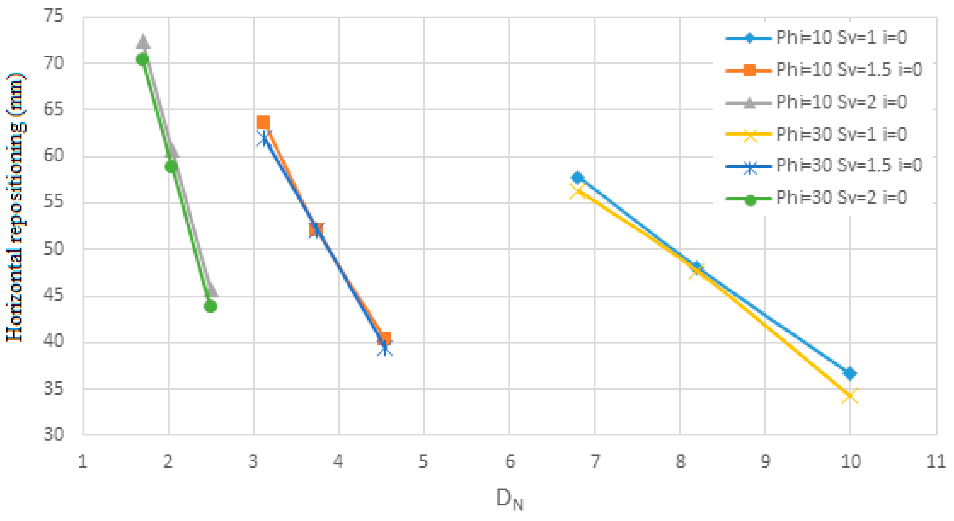
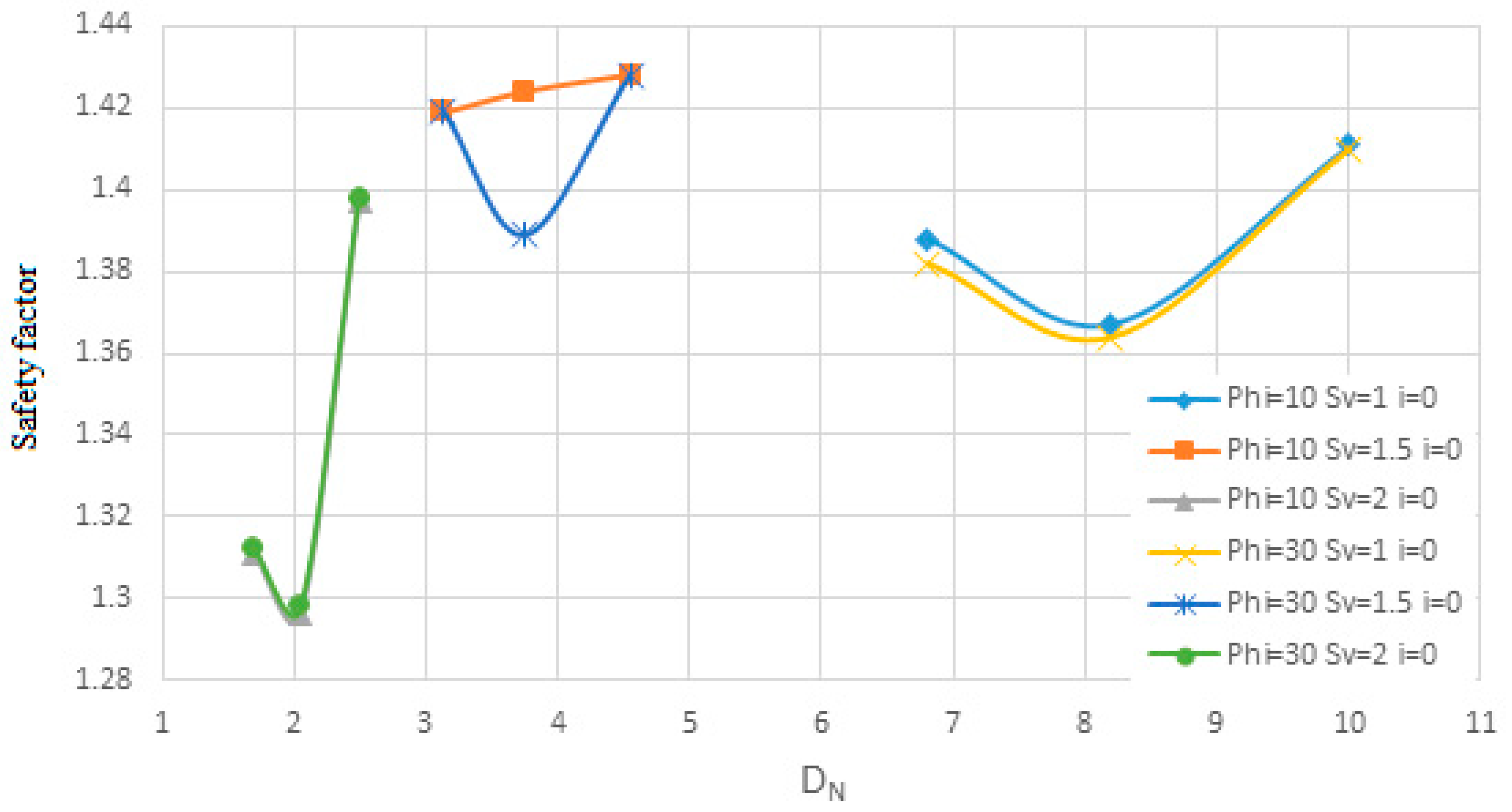
Dn.
Figure 17 and
Figure 18 are shown for soil with an internal friction angle of 23 degrees and cohesion of 22 KN/m
2 and
Sv from 1 to 2 m with the slope of the nails being zero degrees and the diameter of the nails is 10 and 30 mm according to
Dn. At first, the diagrams are shown quantitatively in terms of
Lavg for soil with an internal friction angle of 35 degrees and then for soil with an internal friction angle of 23 degrees and then qualitatively analyzed.
The results from
Figure 11,
Figure 12,
Figure 13 and
Figure 14 indicate that changes in the diameter of rebars used in the nailed wall—specifically diameters of 10, 20, and 30 mm—do not significantly impact horizontal displacement or the safety factor. This suggests that rebar diameter is not a critical determinant in the effectiveness of the nailing arrangement for wall stability.
Furthermore, for the second soil type, it is observed that when nail lengths are short, the horizontal displacement of the wall exceeds permissible limits, even though the safety factor remains within an acceptable range. For instance, in the second soil, with an internal friction angle of 23° and cohesion of 22 kPa, using nails with a diameter of 30 mm and a vertical spacing (Sv) of 1.5 m results in a safety factor of approximately 1.42. However, the horizontal displacement reaches approximately 62 mm, which exceeds acceptable thresholds. Similar trends are observed across most charts for configurations with short nail lengths.
To analyze the influence of nail diameter (Dn), graphs are first presented quantitatively for soil with an internal friction angle of 35°, followed by soil with an internal friction angle of 23°. These results are then qualitatively evaluated to assess the relationship between nail diameter, horizontal displacement, and safety factor.
Figure 15,
Figure 16,
Figure 17 and
Figure 18 investigate the effect of nail diameter on wall displacement and safety factors across varying soil conditions. The findings reveal negligible variations in displacement and safety factor when the nail diameter changes. This suggests that nail diameter plays a limited role under these conditions, possibly due to the overwhelming influence of other parameters like nail length, spacing, and angle. However, it is implied that under certain scenarios—such as soils with lower cohesion or higher plasticity—diameter might have a greater impact.
Based on the results of
Figure 11,
Figure 12,
Figure 13,
Figure 14,
Figure 15,
Figure 16,
Figure 17 and
Figure 18, it can be seen that according to the density of nails on the surface of the wall, the permissible displacement decreases with the increase in the density of nails. The lower the nail density, the steeper the slope of the displacement graph changes, and the higher the nail density, the slower the slope of the displacement graph changes. Similarly, for the allowed safety factor, it can be seen that with a decrease in the density of nails, the slope of the changes in the safety factor graph is faster, and with an increase in the density of nails, the slope of the changes in the safety factor graph is slower. This means that when the area of influence is large, there are many significant changes. For example, for the first soil sample and a nail with a diameter of 30 mm with a zero-degree angle to the horizon and a horizontal and vertical distance of 2 m, the safety factor is 1.258 for the nail density of 1.49 and 1.436 for the nail density of 2.25. Likewise, when the density of nails increases, the slope of the safety factor decreases. For example, for a nail with a diameter of 30 mm, with an angle of 0 degrees to the horizon and a horizontal and vertical distance of 1 m, the safety factor for the density of nail 6 is 1.389 and for the density of nail 9, the safety factor is 1.468.
4.2. The Angle of the Nails Relative to the Horizon (i)
The results of examining the angle of the nails with respect to the horizon for a nail with a diameter of 30 mm are shown in
Figure 19,
Figure 20,
Figure 21,
Figure 22,
Figure 23,
Figure 24,
Figure 25,
Figure 26,
Figure 27,
Figure 28,
Figure 29 and
Figure 30, which show the change in the horizontal lateral location and the safety factor.
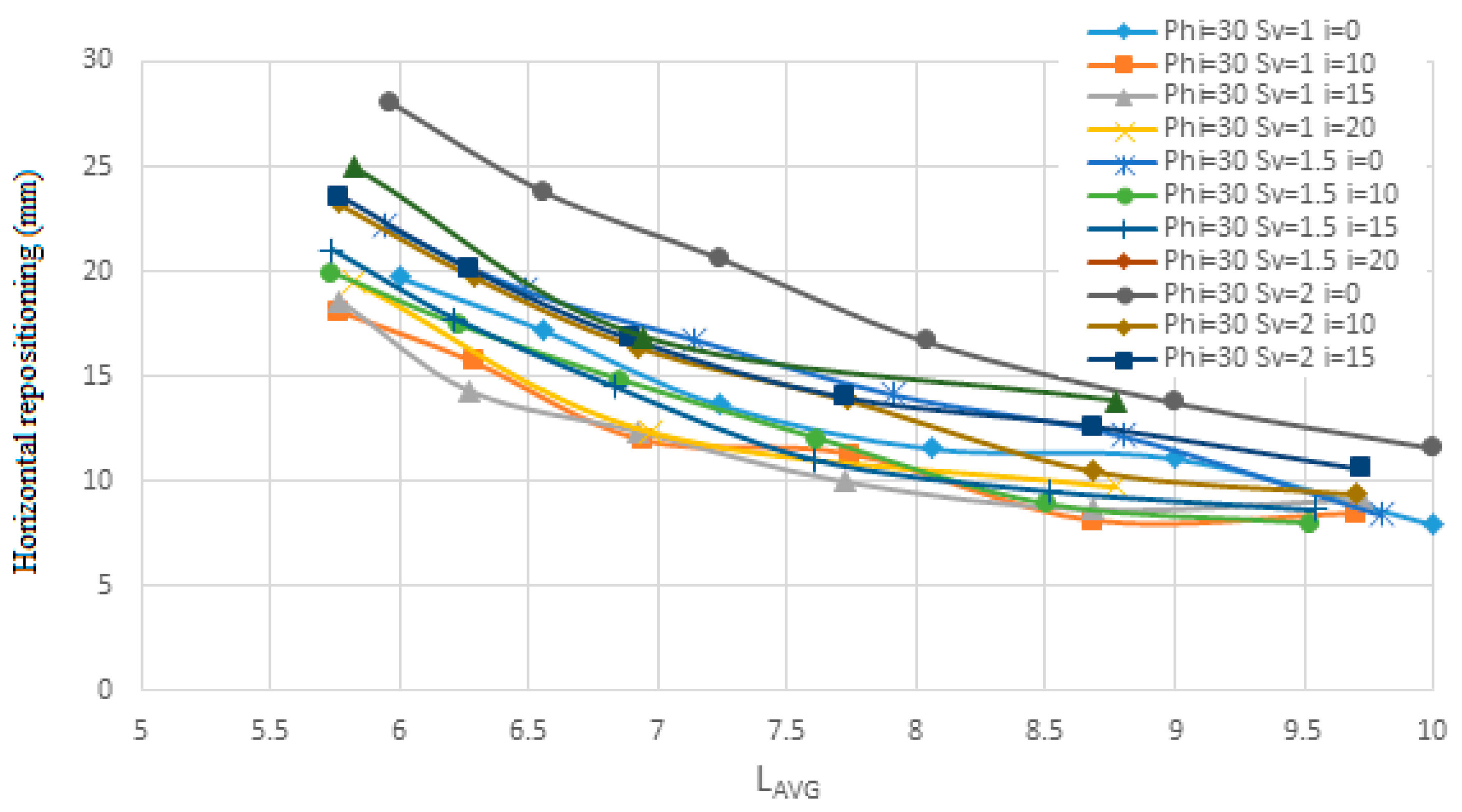
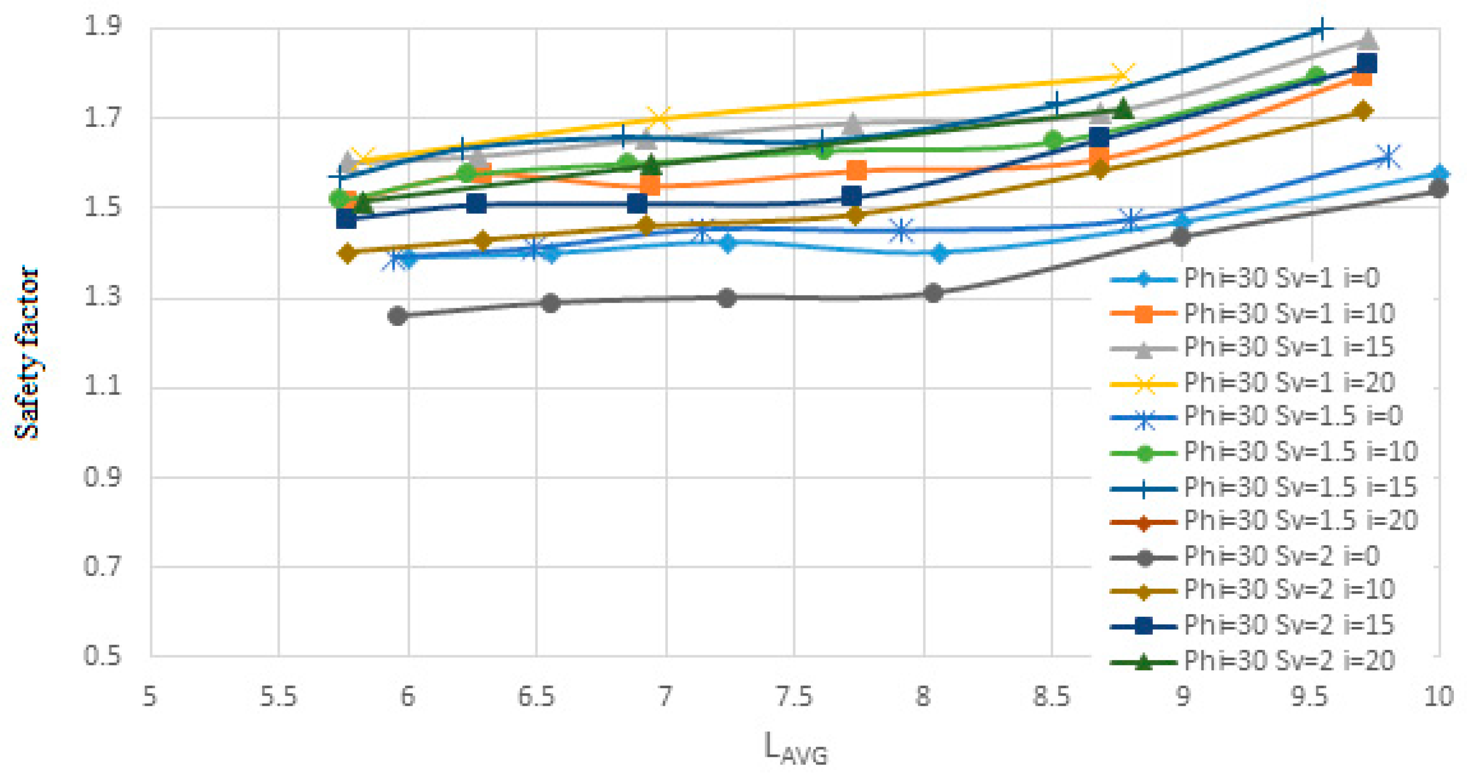
Figure 19 and
Figure 20 are shown in terms of
Lavg for soil with an internal friction angle of 35 degrees and cohesion of 5 KN/m
2 and
Sv from one to two meters and a nail diameter of 30 mm and the angle of the nails with respect to the horizon from zero to twenty degrees.
Figure 21 and
Figure 22 are shown for soil with an internal friction angle of 23 degrees and cohesion of 22 KN/m
2 and
Sv from one to two meters and a nail diameter of 30 mm and the angle of the nails with respect to the horizon from zero to fifteen degrees.
Figure 23 and
Figure 24 are shown for soil with an internal friction angle of 35 degrees and cohesion of 5 KN/m
2 for the upper layer soil at a height of five meters, and soil with an internal friction angle of 23 degrees and cohesion of 22 KN/m
2 for the bottom layer soil at a height of five meters and
Sv from one to two meters and a nail diameter of 30 mm and the angle of the nails with respect to the horizon from zero to fifteen degrees according to
Lavg.
Figure 25 and
Figure 26 are shown in terms of
Lavg for soil with an internal friction angle of 35 degrees and cohesion of 5 KN/m
2 and
Sv from one to two meters and a nail diameter of 30 mm and the angle of the nails with respect to the horizon from zero to twenty degrees.
Figure 27 and
Figure 28 are shown for soil with an internal friction angle of 23 degrees and cohesion of 22 KN/m
2 and
Sv from one to two meters and a nail diameter of 30 mm and the angle of the nails with respect to the horizon from zero to fifteen degree.
Figure 29 and
Figure 30 are shown for soil with an internal friction angle of 35 degrees and cohesion of 5 KN/m
2 for the upper layer soil at a height of five meters, and soil with an internal friction angle of 23 degrees and cohesion of 22 KN/m
2 for the bottom layer soil at a height of five meters and
Sv from one to two meters and a nail diameter of 30 mm and the angle of the nails with respect to the horizon from zero to fifteen degrees in terms of
Dn.
One reason nails are installed at an angle is that grout tends to move within the cavity due to its own weight, and injecting grout under pressure is not cost effective. Additionally, nails installed at an angle to the horizontal can resist both the horizontal (tensile) and vertical (shear) components of the applied forces. In contrast, nails installed without an angle can only resist the horizontal component, often resulting in significant deformations in the wall. Initially, quantitative data are presented in terms of the average length (Lavg) for soil with an internal friction angle of 35 degrees. This is followed by data for soil with an internal friction angle of 23 degrees, and finally for a layered soil structure consisting of a 35-degree internal friction angle layer over a 23-degree internal friction angle layer. These results are then analyzed qualitatively.
For the first soil sample, it can be observed that when the nails are installed at a 10-degree angle relative to the horizontal plane, there is less response to changes in horizontal displacement. The horizontal displacement diagram shows that the displacement solutions tend to stabilize at a constant value, and increasing the restraining length of the nails has a noticeable effect until the solutions no longer show significant changes. It is also evident that for the nail with a 10-degree angle to the horizontal, the safety factor is higher compared to the 0-degree angle, but lower than that of the 15- and 20-degree angles. However, this difference is minimal, around 0.1. According to the diagram, most curves show an initial increase in the confidence coefficient with either a low or high slope, followed by a near-flat slope at zero or very small values, and then a sharp increase again with a larger slope as the nail length increases, which aligns with expected behavior.
For the second soil sample, the 10-degree angle relative to the horizontal plane results in smaller responses in horizontal displacement and safety factor compared to the 0- and 15-degree angles. This trend is consistent for the layered soil as well. In
Figure 22, it can be seen that the displacement for a nail with a 10-degree angle to the horizontal plane, with a nail diameter of 30 mm and S
v equal to 1 m, decreases from 18.12 mm to 8.45 mm. For a nail with a 15-degree angle and the same diameter and S
v, the displacement decreases from 18.56 mm to 9.17 mm. Almost all graphs follow this trend.
To assess the effect of nail angle relative to the horizon, the data are first presented quantitatively in terms of Dn for soil with an internal friction angle of 35 degrees, followed by data for soil with an internal friction angle of 23 degrees, and finally for a layered soil structure with 35-degree internal friction angle soil on top and 23-degree soil below. These results are shown for Sv values ranging from 1 to 2 m, with variable nail angles and a constant nail diameter of 30 mm. The results are then analyzed.
Figure 25,
Figure 26,
Figure 27,
Figure 28,
Figure 29 and
Figure 30 evaluate the effect of nail angles on layered soil systems, comprising different soil properties at various depths. These figures illustrate the relationship between nail inclination and two key performance indicators: horizontal displacement of the wall and safety factor, across three soil conditions—first soil, second soil, and layered soil. From
Figure 25,
Figure 27 and
Figure 29, which display horizontal displacement trends, it is evident that nail angles around 10° consistently minimize lateral movements compared to steeper or shallower inclinations. This is most pronounced in
Figure 29, where layered soils respond favorably to the 10° configuration due to improved load distribution across soil interfaces with differing stiffness. The reduced displacement observed indicates enhanced lateral support provided by optimally inclined nails.
Figure 26,
Figure 28 and
Figure 30, which focus on safety factors, show a similar trend: the 10° inclination yields the highest safety factors in all three soil types. Specifically,
Figure 30 highlights that in layered soils, this angle effectively balances vertical and horizontal load transfer, increasing soil–nail interaction and stabilizing the structure under excavation-induced stress. The consistent elevation in safety factor at this angle supports its role as the most effective configuration for layered systems. Additionally, the figures collectively show that increasing the angle of nails leads to higher nail density due to geometric constraints. This higher density, in turn, results in lower displacement and increased structural stability, as seen by the flatter slopes in displacement and safety factor change curves. Conversely, lower nail densities, associated with steeper angles, produce steeper response slopes, indicating reduced effectiveness. As shown, the enhanced performance at a 10° angle—demonstrated in all figures through reduced displacements and elevated safety factors—confirms its suitability for reinforcing complex soil structures.
4.3. Effect of Increasing Nail Length Behind the Rupture Wedge
It is well established that for the horizontal displacement and safety factor of the pit wall to reach acceptable values, the length of the nails must extend beyond the rupture surface. This ensures effective performance against sliding and displacement. Therefore, the length of the nails behind the rupture wedge is a critical parameter included in all models. As seen in the results from other models, increasing the length of the nails behind the rupture wedge leads to a reduction in horizontal displacement and an increase in the reliability factor. However, these improvements are only significant up to a certain point, beyond which further increases in nail length do not yield substantial changes in horizontal displacement or safety factor. This restraining length depends on the type of soil, with some soils requiring a greater length and others requiring less.
For sloped backfill scenarios, results suggest that increasing the nail angle to 15° and extending nail length by at least 1 m beyond the wedge surface significantly mitigates lateral movement. Additionally, denser nail arrangements (Sv = 1.0 m, Sh = 1.0 m) yield safety factors above 1.5 under these conditions. These strategies should be prioritized when dealing with inclined backfill.
The key takeaway from the previous models and the above graphs is that beyond a certain threshold, increasing the length of restraint does not significantly affect horizontal displacement or the safety factor. The general results of the effects of changes in the arrangement of nailing, nail diameter, the angle of nails relative to the horizon (i), and the increase in nail length behind the rupture wedge are summarized in
Table A2.
The results obtained from the finite element analysis not only offer theoretical insight but are also directly transferable to practical geotechnical engineering applications. The modeling scenario, derived from a real-world urban excavation in Mashhad, aligns with commonly observed site conditions and construction practices, especially within densely populated and infrastructure-constrained areas. The recommendation of a 10° nail inclination as an optimal configuration for balancing tensile and shear resistance is of particular value, as it offers a data-driven design guideline with quantifiable improvements in deformation control and safety factor. Similarly, the identification of diminishing returns beyond a 5 m nail length offers practical design boundaries that can help avoid unnecessary material use and cost escalation.
4.4. Sensisitivity Analysis
The regression model presented in Equation (6) estimates the horizontal displacement (H-disp) as a function of several key parameters related to soil nailing: nail density (Dn), vertical spacing (Sv), nail length beyond the rupture wedge (L-prime), and nail inclination angle (i). The equation includes linear terms for each factor, two-way interaction terms (e.g., Dn × Sv), and quadratic terms (e.g., Sv
2), allowing for a comprehensive representation of both direct and interactive influences on horizontal displacement. This model structure enables the capture of complex, nonlinear behavior in excavation stability performance.
A sensitivity analysis using the ANOVA model (
Table 10) reveals which parameters significantly influence the response variable, H-disp. The interaction between vertical spacing and nail inclination (CD) is found to be statistically significant with a
p-value of 0.0154, indicating that the combined effect of Sv and i substantially affects horizontal displacement. Additionally, the quadratic term for nail inclination (D
2) is significant (
p = 0.0135), suggesting a nonlinear relationship between the angle of the nails and wall displacement, where displacement does not change linearly with increasing inclination. These two findings underscore the critical role of nail inclination, both independently and in interaction with spacing, in influencing excavation stability.
Other terms, such as the main effects of Dn, Sv, and L-prime, as well as their interactions (e.g., AB, AC, AD), are statistically insignificant (p > 0.05), though some exhibit moderate F-values. For example, the quadratic term B2 (Sv2) approaches significance (p = 0.0832), hinting at a potential nonlinear effect of nail spacing that may merit further investigation. Overall, the model highlights that while linear effects are limited, specific interaction and nonlinear terms—especially those involving nail angle—play a pivotal role in controlling horizontal displacement in soil-nailed excavations. Finally, according to F-value and p-value, it can be understood that the importance of factors on H-displacement is L-prime > i > Sv > Dn.
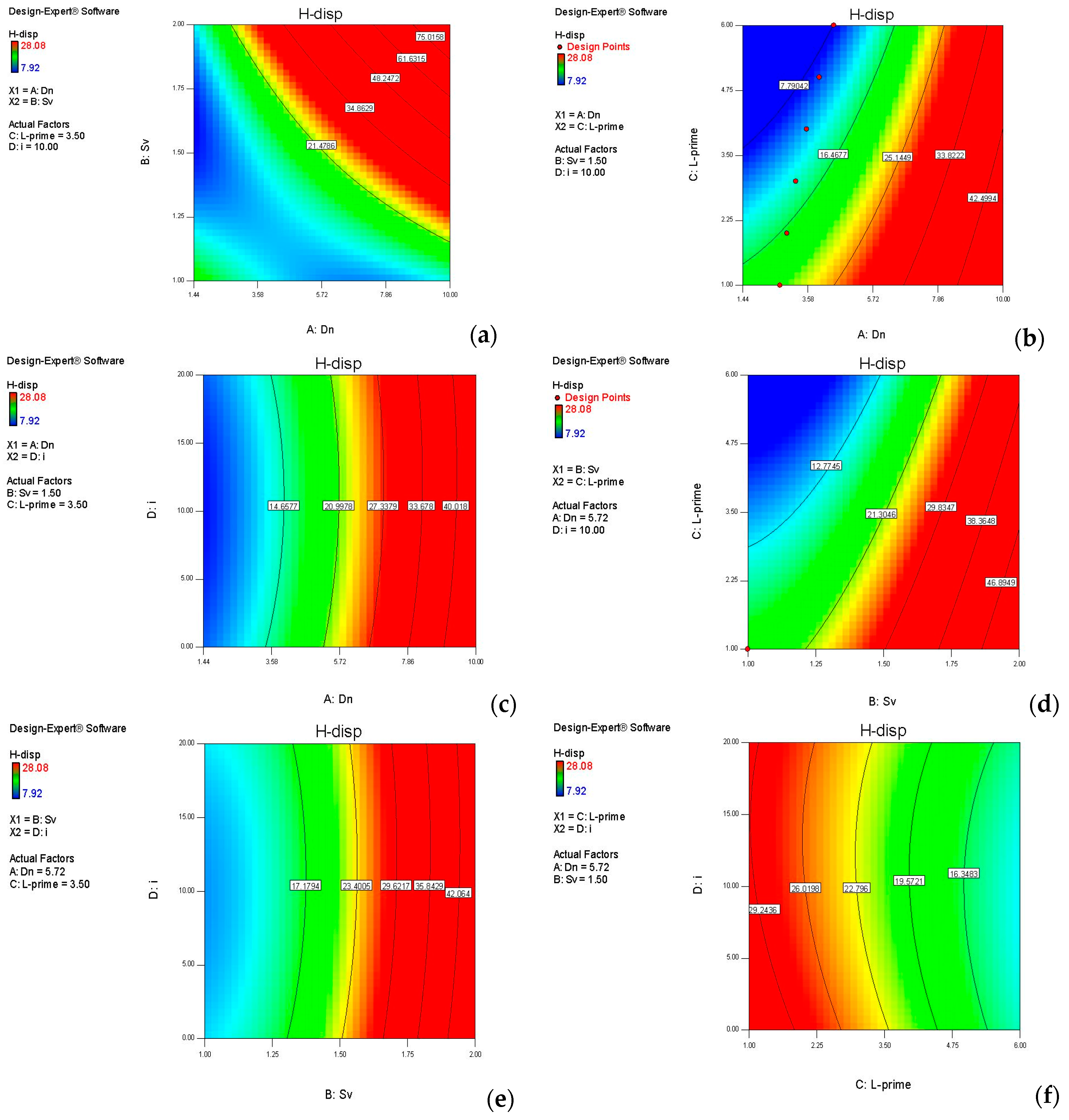
The dual sensitivity analysis illustrated in
Figure 31a–f provides a comprehensive view of how horizontal displacement (H-disp) responds to the interaction of key soil nailing parameters. These contour plots, generated using Design-Expert software (
https://cdn.statease.com/media/public/documents/Software_Flyer.pdf, accessed on 22 March 2025), facilitate the visualization of combined effects from variable pairs, while holding other factors constant. The displacement values are mapped on a gradient scale from blue (minimum ~7.92 mm) to red (maximum ~28.98 mm), offering a clear indication of zones of high and low excavation stability.
In
Figure 31a, the interaction between Dn and Sv is examined. The plot reveals a pronounced nonlinear trend, where higher displacement occurs when Dn is low and Sv is high. Conversely, the region with high Dn and low Sv corresponds to minimal displacement. This demonstrates that increasing the density of nails while decreasing their vertical spacing significantly enhances wall stability. The sharp gradient observed reinforces the statistically significant interaction (CD) identified in the ANOVA analysis (
p = 0.0154), emphasizing that this parameter combination plays a dominant role in influencing H-disp.
Figure 31b explores the combined effect of Dn and L-prime (length beyond the rupture wedge). The contours display a diagonal gradient, indicating that increasing both Dn and L-prime together contributes to a marked reduction in horizontal displacement. However, the trend is smoother compared to
Figure 31a, suggesting a weaker interaction. This is consistent with the ANOVA results, where this interaction (AC) was not statistically significant (
p = 0.8426), yet still contributes meaningfully in practical optimization scenarios by reinforcing that both high nail density and increased anchoring length yield improved performance.
In
Figure 31c, the interaction of Dn and inclination angle (i) is presented. The plot shows that increasing Dn generally reduces displacement across all values of i, but changes along the i-axis are relatively minor, resulting in almost vertical contour lines. This supports the conclusion that Dn is more influential than inclination in this pairing. Although this interaction (AD) is not statistically significant (
p = 0.2847), it suggests that nail inclination alone does not drastically alter the system’s stability unless coupled with sufficient density.
Figure 31d shows the interaction between Sv and L-prime, where a gradual improvement in displacement is seen as L-prime increases and Sv decreases. This behavior implies that longer nails can somewhat offset the negative effects of wider spacing, though not entirely. The contour curvature indicates some level of interaction, but again, this was statistically insignificant in the ANOVA (BD,
p = 0.3375). Nevertheless, the combination reflects practical insights for design: maintaining tight spacing or compensating with increased embedment length helps control wall deformation.
The relationship between Sv and inclination angle (i) is displayed in
Figure 31e. This plot exhibits curved contours, suggesting a more complex interaction. Displacement increases sharply at high Sv values regardless of inclination, while improvements are observed with decreasing Sv. The inclination parameter exerts additional fine-tuning effects. This finding is aligned with the earlier ANOVA result where the quadratic term for i
2 was statistically significant (
p = 0.0135), confirming the nonlinear influence of inclination on displacement when coupled with spacing.
Finally,
Figure 31f presents the interplay between L-prime and i. The contours are relatively smooth and horizontal, showing that increases in L-prime have a more pronounced effect on reducing displacement than changes in inclination. This supports the conclusion that nail length beyond the failure surface is a key driver of displacement control, while inclination mainly provides secondary modulation. The gentle gradients observed reflect the non-significance of this interaction (CD) in the ANOVA results, though the term D
2 for inclination remains influential individually.
4.5. Discussion on Sustainability
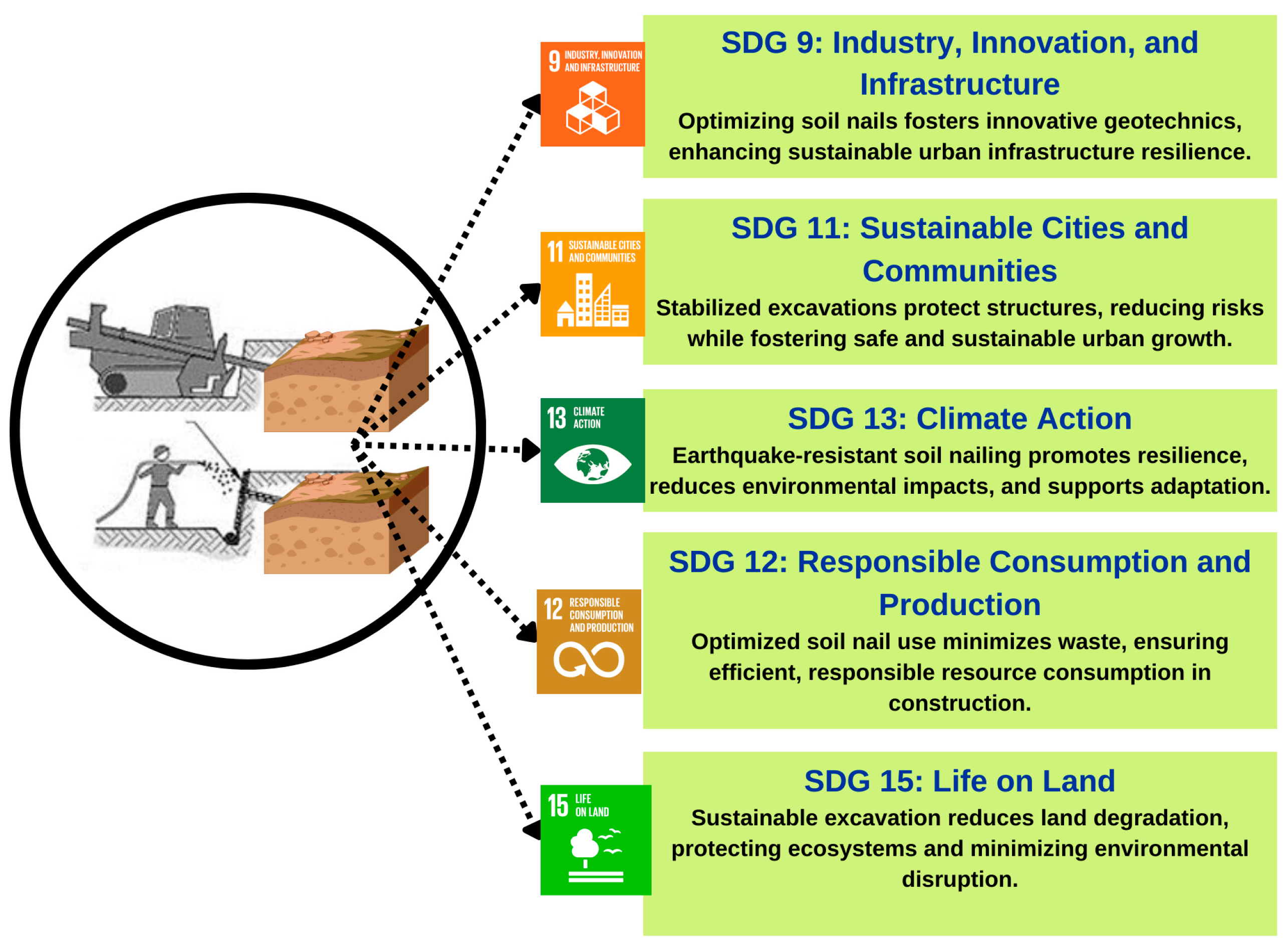
The research presented in this study aligns with several Sustainable Development Goals (SDGs), particularly SDG 9 (Industry, Innovation, and Infrastructure), SDG 11 (Sustainable Cities and Communities), SDG 12 (Responsible Consumption and Production), SDG 13 (Climate Action), and SDG 15 (Life on Land) (
Figure 32). By focusing on optimizing soil nail configurations through advanced geotechnical methods, this research supports the development of resilient and sustainable urban infrastructure, addressing the challenges of rapid urbanization while minimizing environmental impact. The research enhances safety and stability in urban construction, contributing to the creation of inclusive and secure communities. Furthermore, by promoting efficient resource use, such as minimizing material waste through optimal nail placement, the study supports responsible consumption practices. Its emphasis on earthquake-resistant and environmentally conscious techniques aligns with the goals of climate resilience and disaster adaptation. Additionally, the use of sustainable excavation practices helps reduce land degradation and protect terrestrial ecosystems. Overall, this work underscores the critical role of sustainable engineering solutions in advancing global sustainability objectives.
As a quantitative contribution to SDG 9 (Industry, Innovation, and Infrastructure), the optimization process using finite element analysis in PLAXIS led to a 58.6% reduction in horizontal displacement (from 28.08 mm to 11.61 mm) and a 22.2% increase in the safety factor (from 1.26 to 1.54) by increasing nail length from 1 m to 6 m. Additionally, optimizing nail inclination to 10° at a 1 m spacing further enhanced performance, reducing displacement to 18.12 mm and raising the safety factor to 1.52. These improvements directly contribute to more resilient and reliable infrastructure through enhanced excavation safety and structural efficiency. In support of SDG 12 (Responsible Consumption and Production), the study shows that increasing nail length beyond 4 m results in diminishing returns—yielding less than a 3% increase in safety factor—thus discouraging unnecessary material use.
The outcomes of our research can be effectively contextualized by directly comparing them with the works of Basu et al. (2015) [
40] and Abreu et al. (2008) [
41]. Basu et al. [
40] emphasizes the integration of sustainability in geotechnical engineering as a multi-dimensional objective, incorporating resilience, economic viability, and environmental protection. They advocate for embedding sustainability principles from the early planning stages of geotechnical projects. Our study aligns with this vision by focusing on the optimization of soil nail configurations—specifically the inclination and density of nails—to improve structural efficiency and reduce material use. Unlike Basu et al., whose work is primarily conceptual and policy driven, our research offers a quantitative and applied extension of these sustainability goals, showing that optimized configurations not only enhance safety but also contribute to resource efficiency, thereby reducing the environmental footprint of excavation support systems.
Abreu et al. [
41] investigates the integration of reliability-based design (RBD) methods in geotechnical engineering, highlighting the significance of probabilistic approaches for managing uncertainties in soil properties and behavior. While our study does not directly employ a probabilistic framework, it incorporates systematic parametric analysis and optimization techniques that serve a parallel function—ensuring robustness and safety across varying soil conditions. The key distinction lies in methodology: Abreu et al. rely on probabilistic modeling, whereas our work emphasizes deterministic optimization informed by performance metrics such as safety factors and displacement. Nonetheless, both approaches converge on the goal of enhancing the reliability and efficiency of geotechnical solutions. Therefore, it can be said that our research complements and extends the insights of these studies [
40,
41] by providing a focused application that bridges conceptual sustainability frameworks and reliability goals with a practical and numerical optimization methodology.
While the study validates its findings using prior research [
39] as mentioned, further elaboration on the validation process could enhance its credibility. A comparison with the results of Mohamed et al. (2021) [
42] and Prahatheswaran et al. (2020) [
43] highlights key areas of alignment and divergence. Similar to Mohamed et al. [
42], this study confirms that increasing nail length reduces lateral displacement and enhances stability up to a certain threshold, beyond which the benefits plateau. Additionally, both studies agree that an optimal nail inclination, particularly around 10°, significantly minimizes deformation and improves load-bearing capacity. The use of closer nail spacing as a critical factor for enhanced stability is consistently observed across all three studies. Similarly, compared to Prahatheswaran and Ashika [
43], this study offers more detailed insights into the economic implications of optimizing nail configurations, particularly at lower slope angles. While Prahatheswaran and Ashika focus on steeper slopes and the behavior of circular slip surfaces, this study’s findings are more applicable to scenarios requiring lower inclinations for enhanced stability.
The environmental factors affecting the performance and sustainability of soil nails are comprehensively addressed in Yazdani et al. [
44], providing a strong response to the reviewer’s concern. First, the study highlights that the main contributors to environmental burden in soil nailing are cement and steel, both of which are integral to grout and reinforcement elements. These materials are identified as the dominant sources of carbon emissions, accounting for up to 95% of total emissions in high-angle, high-height slope configurations. This underscores how material choice directly influences the environmental footprint of the stabilization method. Furthermore, the geometry of the slope significantly modifies the environmental impact. For example, as slope height and inclination increase, the amount of required steel bars and grout rises substantially, leading to elevated emissions. At a height of 20 m and a 75° angle, nailed slopes can emit up to 11,940.5 kg CO
2; per 1.2 m, compared to lower emissions in moderate geometries. This finding illustrates how geometric constraints realistically amplify both material demand and environmental cost. Therefore, this parametric evaluation of the nailing processes could have significant effects on the environment.
5. Conclusions
This study investigated the optimal arrangement of soil nails in excavation support systems using numerical and finite element methods through PLAXIS software (V22). The primary aim was to evaluate how key parameters—nail length, diameter, angle, and spacing—along with varying soil properties, influence wall stability and excavation safety. Findings consistently demonstrate that increasing nail length leads to significant reductions in horizontal wall displacement and improvements in the safety factor, although these benefits taper off beyond a certain threshold. For example, extending nail lengths from 1 m to 6 m decreased displacement from 28.08 mm to 11.61 mm and increased the safety factor from 1.26 to 1.54 (at 2 m spacing and 30 mm diameter). Moreover, increasing nail length beyond 5 m (for Sh = 2 m, d = 30 mm) leads to minimal improvement in displacement or safety factor, indicating a performance threshold. For instance, increasing length from 5 m to 6 m improved the safety factor from 1.539 to 1.54, with only a 0.02 gain, thus recommending a practical limit around 5 m for similar conditions. Nail diameter showed only marginal influence, indicating that material optimization should prioritize length and angle over diameter. The nail angle emerged as a critical factor, with a 10° inclination yielding optimal structural performance due to a favorable balance between tensile and shear forces—achieving displacement of 18.12 mm and a safety factor of 1.52 at 1 m spacing. Furthermore, soil type played a decisive role: coarse-grained soils with higher internal friction angles (e.g., 35°) performed better than fine-grained soils (e.g., 23°), leading to greater overall stability. Together, these findings emphasize the importance of modified design in soil nailing—optimizing geometric parameters in accordance with site-specific geotechnical conditions to enhance both safety and material efficiency.
However, this study is not without limitations. The analyses were based on deterministic simulations without incorporating probabilistic uncertainty in soil parameters or construction variabilities. Additionally, the study assumes idealized boundary conditions and homogeneity within soil layers, which may not fully reflect field complexities. Future research should aim to integrate probabilistic reliability-based methods, validate findings through field experiments, and explore the influence of dynamic loads or long-term environmental effects on nail performance.


 ,
, 
