Medical Cyclotron Solid Target Preparation by Ultrathick Film Magnetron Sputtering Deposition

 , , , ,
Abstract
:
1. Introduction
2. Materials and Methods
2.1. Materials
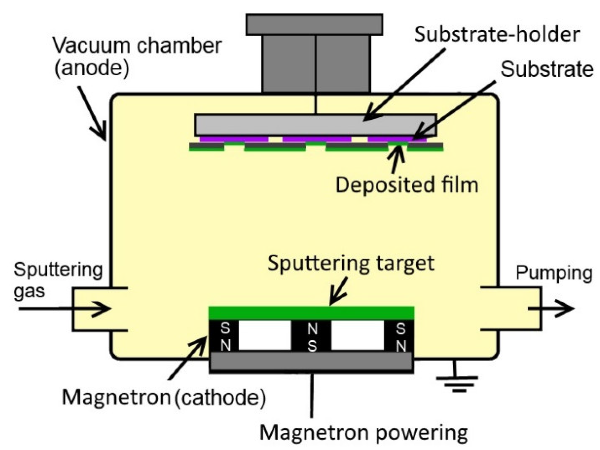
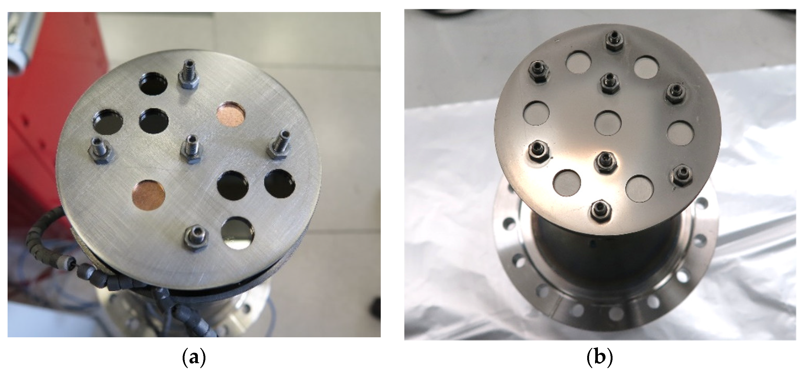
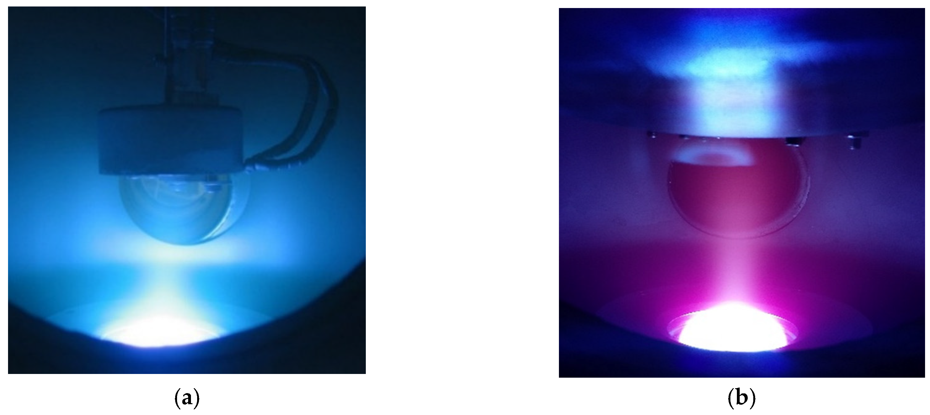
2.2. Deposition System
2.3. Deposit Analysis
2.4. Cyclotron Tests
2.5. Estimation of 89Zr Expected Yields
3. Results and Discussion
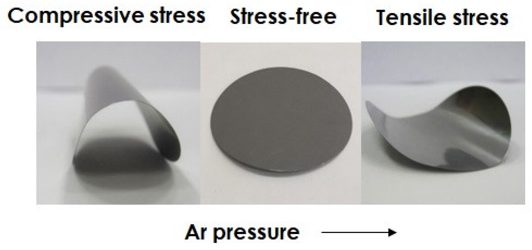
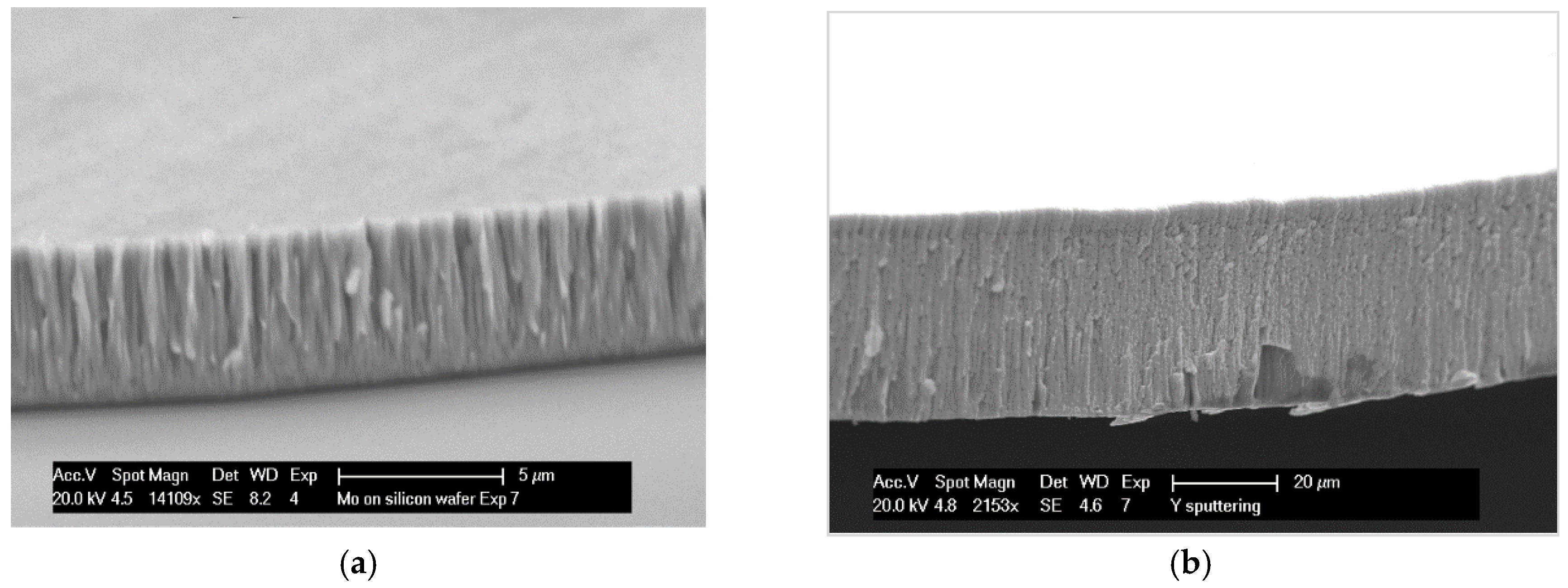
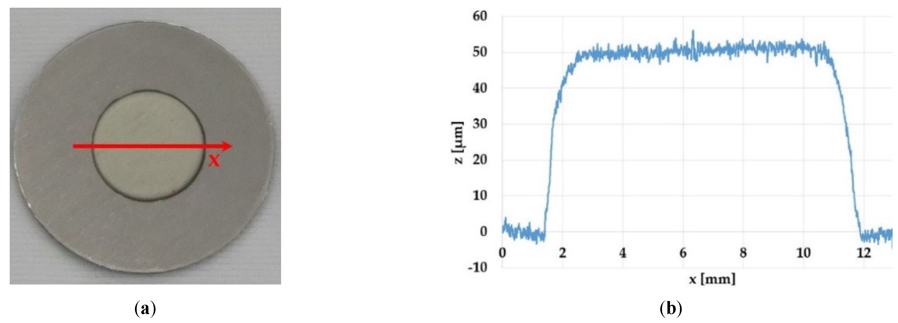
3.1. Sputtering Parameters Optimization
3.2. Cyclotron Test
4. Conclusions
5. Patents
Author Contributions
Funding
Acknowledgments
Conflicts of Interest
References
- Stolarz, A. Target preparation for research with charged projectiles. J. Radioanal. Nucl. Chem. 2014, 299, 913–931. [Google Scholar] [CrossRef] [PubMed]
- IAEA. Cyclotron Based Production of Technetium-99m.; IAEA: Vienna, Austria, 2017; ISBN 978-92-0-102916-4. [Google Scholar]
- Skliarova, H.; Cisternino, S.; Cicoria, G.; Marengo, M.; Palmieri, V. Innovative Target for Production of Technetium-99m by Biomedical Cyclotron. Molecules 2019, 24, 25. [Google Scholar] [CrossRef] [PubMed]
- Schaffer, P.; Benard, F.; Buckley, K.R.; Hanemaayer, V.; Manuela, C.H.; Klug, J.A.; Kovacs, M.S.; Morley, T.J.; Ruth, T.J.; Valliant, J.; et al. Processes, systems, and apparatus for cyclotron production of technetium-99m. Patent US 2013/0301769 A1; United States: TRIUMF, 14 November 2013. [Google Scholar]
- Gagnon, K.; Wilson, J.S.; Holt, C.M.B.; Abrams, D.N.; McEwan, A.J.B.; Mitlin, D.; McQuarrie, S.A. Cyclotron production of 99mTc: Recycling of enriched 100Mo metal targets. Appl. Radiat. Isot. 2012, 70, 1685–1690. [Google Scholar] [CrossRef] [PubMed]
- Wilson, J.; Gagnon, K.; McQuarrie, S. Production of technetium from a molybdenum metal target. Patent US 2014/0029710A1; United States: University of Alberta, 30 January 2014. [Google Scholar]
- Stolarz, A.; Kowalska, J.A.; Jasiński, P.; Janiak, T.; Samorajczyk, J. Molybdenum targets produced by mechanical reshaping. J. Radioanal. Nucl. Chem. 2015, 305, 947–952. [Google Scholar] [CrossRef] [PubMed]
- Morrall, P.S. The Target Preparation Laboratory at Daresbury. Nucl. Instrum. Methods Phys. Res. Sect. Accel. Spectrometers Detect. Assoc. Equip. 2008, 590, 118–121. [Google Scholar] [CrossRef]
- Manenti, S.; Holzwarth, U.; Loriggiola, M.; Gini, L.; Esposito, J.; Groppi, F.; Simonelli, F. The excitation functions of 100Mo(p,x)99Mo and 100Mo(p,2n)99mTc. Appl. Radiat. Isot. 2014, 94, 344–348. [Google Scholar] [CrossRef] [PubMed]
- Zweit, J.; Downey, S.; Sharma, H.L. Production of no-carrier-added zirconium-89 for positron emission tomography. Int. J. Rad. Appl. Instrum. [A] 1991, 42, 199–201. [Google Scholar] [CrossRef]
- NISHIKATA, K.; Kimura, A.; Ishida, T.; KITAGISHI, S.; Tsuchiya, K.; Akiyama, H.; Nagakura, M.; Suzuki, K. Method of producing radioactive molybdenum. Patent US 13675769; United States. Japan Atomic Energy Agency, 30 May 2013. [Google Scholar]
- Zeisler, S.K.; Hanemaayer, V.; Buckley, K.R. Target system for irradiation of molybdenum with particle beams. Patent US 2017/0048962A1; United States: TRIUMF, 16 February 2017. [Google Scholar]
- Schaffer, P.; Bénard, F.; Bernstein, A.; Buckley, K.; Celler, A.; Cockburn, N.; Corsaut, J.; Dodd, M.; Economou, C.; Eriksson, T.; et al. Direct Production of 99mTc via 100Mo(p,2n) on Small Medical Cyclotrons. Phys. Procedia 2015, 66, 383–395. [Google Scholar] [CrossRef]
- Zyuzin, A.; Guérin, B.; van Lier, E.; Tremblay, S.; Rodrigue, S.; Rousseau, J.A.; Dumulon-Perreault, V.; Lecomte, R.; van Lier, J.E. Cyclotron Production of 99mTc. In Proceedings of the WTTC13, Roskilde, Denmark, 26–28 July 2010. [Google Scholar]
- Avetisyan, A.; Dallakyan, R.; Sargsyan, R.; Melkonyan, A.; Mkrtchyan, M.; Harutyunyan, G.; Dobrovolsky, N. The powdered molybdenum target preparation technology for 99mTc production on C18 cyclotron. IJEIT 2015, 4, 8. [Google Scholar]
- Taghilo, M. Cyclotron production of 89Zr: A potent radionuclide for positron emission tomography. Int. J. Phys. Sci. 2012, 7. [Google Scholar] [CrossRef]
- Morley, T.J.; Penner, L.; Schaffer, P.; Ruth, T.J.; Bénard, F.; Asselin, E. The deposition of smooth metallic molybdenum from aqueous electrolytes containing molybdate ions. Electrochem. Commun. 2012, 15, 78–80. [Google Scholar] [CrossRef]
- Kazimierczak, H.; Ozga, P.; Socha, R.P. Investigation of electrochemical co-deposition of zinc and molybdenum from citrate solutions. Electrochimica Acta 2013, 104, 378–390. [Google Scholar] [CrossRef]
- Queern, S.L.; Aweda, T.A.; Massicano, A.V.F.; Clanton, N.A.; El Sayed, R.; Sader, J.A.; Zyuzin, A.; Lapi, S.E. Production of Zr-89 using sputtered yttrium coin targets. Nucl. Med. Biol. 2017, 50, 11–16. [Google Scholar] [CrossRef] [PubMed]
- Meijs, W.E.; Herscheid, J.D.M.; Haisma, H.J.; Wijbrandts, R.; van Langevelde, F.; Van Leuffen, P.J.; Mooy, R.; Pinedo, H.M. Production of highly pure no-carrier added 89Zr for the labelling of antibodies with a positron emitter. Appl. Radiat. Isot. 1994, 45, 1143–1147. [Google Scholar] [CrossRef]
- Verel, I.; Visser, G.W.M.; Boellaard, R.; Walsum, M.S.; Snow, G.B.; Dongen, G.A.M.S. van 89Zr Immuno-PET: Comprehensive Procedures for the Production of 89Zr-Labeled Monoclonal Antibodies. J. Nucl. Med. 2003, 44, 1271–1281. [Google Scholar]
- Jalilian, A.; Targholizadeh, H.; Raisali, G.; Zandi, H.; Kamali Dehgan, M. Direct Technetium radiopharmaceuticals production using a 30MeV Cyclotron. DARU J. Fac. Pharm. Tehran Univ. Med. Sci. 2011, 19, 187–192. [Google Scholar]
- Maier, H.J.; Friebel, H.U.; Frischke, D.; Grossmann, R. State of the art of high vacuum sputter deposition of nuclear accelerator targets. Nucl. Instrum. Methods Phys. Res. Sect. Accel. Spectrometers Detect. Assoc. Equip. 1993, 334, 137–141. [Google Scholar] [CrossRef]
- Folger, H.; Klemm, J.; Muller, M. Preparation of Nuclear Accelerator Targets by Focused Ion Beam Sputter Deposition. IEEE Trans. Nucl. Sci. 1983, 30, 1568–1572. [Google Scholar] [CrossRef]
- Esposito, J.; Bettoni, D.; Boschi, A.; Calderolla, M.; Cisternino, S.; Fiorentini, G.; Keppel, G.; Martini, P.; Maggiore, M.; Mou, L.; et al. LARAMED: A Laboratory for Radioisotopes of Medical Interest. Molecules 2019, 24, 20. [Google Scholar] [CrossRef]
- Esposito, J.; Vecchi, G.; Pupillo, G.; Taibi, A.; Uccelli, L.; Boschi, A.; Gambaccini, M. Evaluation of Mo 99 and Tc 99 m Productions Based on a High-Performance Cyclotron. Sci. Technol. Nucl. Install. 2013, 2013, 1–14. [Google Scholar] [CrossRef]
- Boschi, A.; Martini, P.; Pasquali, M.; Uccelli, L. Recent achievements in Tc-99m radiopharmaceutical direct production by medical cyclotrons. Drug Dev. Ind. Pharm. 2017, 43, 1402–1412. [Google Scholar] [CrossRef]
- Martini, P.; Boschi, A.; Cicoria, G.; Zagni, F.; Corazza, A.; Uccelli, L.; Pasquali, M.; Pupillo, G.; Marengo, M.; Loriggiola, M.; et al. In-house cyclotron production of high-purity Tc-99m and Tc-99m radiopharmaceuticals. Appl. Radiat. Isot. 2018, 139, 325–331. [Google Scholar] [CrossRef]
- Uzunov, N.M.; Melendez-Alafort, L.; Bello, M.; Cicoria, G.; Zagni, F.; De Nardo, L.; Selva, A.; Mou, L.; Rossi-Alvarez, C.; Pupillo, G.; et al. Radioisotopic purity and imaging properties of cyclotron-produced 99m Tc using direct 100 Mo(p, 2 n) reaction. Phys. Med. Biol. 2018, 63, 185021. [Google Scholar] [CrossRef]
- Martini, P.; Boschi, A.; Cicoria, G.; Uccelli, L.; Pasquali, M.; Duatti, A.; Pupillo, G.; Marengo, M.; Loriggiola, M.; Esposito, J. A solvent-extraction module for cyclotron production of high-purity technetium-99m. Appl. Radiat. Isot. 2016, 118, 302–307. [Google Scholar] [CrossRef]
- van de Watering, F.C.J.; Rijpkema, M.; Perk, L.; Brinkmann, U.; Oyen, W.J.G.; Boerman, O.C. Zirconium-89 Labeled Antibodies: A New Tool for Molecular Imaging in Cancer Patients. BioMed Res. Int. 2014, 2014, 1–13. [Google Scholar] [CrossRef]
- Jalilian, A.R.; Osso, J.A. Production, applications and status of zirconium-89 immunoPET agents. J. Radioanal. Nucl. Chem. 2017, 314, 7–21. [Google Scholar] [CrossRef]
- Kasbollah, A.; Eu, P.; Cowell, S.; Deb, P. Review on Production of 89Zr in a Medical Cyclotron for PET Radiopharmaceuticals. J. Nucl. Med. Technol. 2013, 41, 35–41. [Google Scholar] [CrossRef]
- Severin, G.W.; Engle, J.W.; Nickles, R.J.; Barnhart, T.E. 89Zr Radiochemistry for PET. Med. Chem. Shariqah United Arab Emir. 2011, 7, 389–394. [Google Scholar]
- Thornton, J.A. Influence of apparatus geometry and deposition conditions on the structure and topography of thick sputtered coatings. J. Vac. Sci. Technol. 1974, 11, 666–670. [Google Scholar] [CrossRef]
- Hoffman, D.W.; Thornton, J.A. Internal stresses in sputtered chromium. Thin Solid Films 1977, 40, 355–363. [Google Scholar] [CrossRef]
- Cicoria, G.; Pancaldi, D.; Piancastelli, L.; Giovaniello, G.; Bianconi, D.; Bollini, D.; Menapace, E.; Givollani, S.; Pettinato, C.; Spinelli, A.; et al. Marengo Development and Operational Test of a Solid Target for the Pettrace Cyclotron. In Proceedings of the 13th European Symposium on Radiopharmacy and Radiopharamceuticals, Lucca, Italy, 30 March 30–2 April 2006; pp. 3–4. [Google Scholar]
- Ciarmatori, A.; Cicoria, G.; Pancaldi, D.; Infantino, A.; Boschi, S.; Fanti, S.; Marengo, M. Some experimental studies on 89 Zr production. Radiochim. Acta 2011, 99, 631–634. [Google Scholar] [CrossRef]
- Radionuclide Yield Calculator - ARRONAX. Available online: http://www.cyclotron-nantes.fr/spip.php?article373 (accessed on 12 March 2019).
- James Ziegler - SRIM & TRIM. Available online: http://www.srim.org/ (accessed on 12 March 2019).
- EXFOR: Experimental Nuclear Reaction Data. Available online: https://www.nndc.bnl.gov/exfor/exfor.htm (accessed on 12 March 2019).
- Omara, H.M.; Hassan, K.F.; Kandil, S.A.; Hegazy, F.E.; Saleh, Z.A. Proton induced reactions on 89Y with particular reference to the production of the medically interesting radionuclide 89Zr. Radiochim. Acta 2009, 97. [Google Scholar] [CrossRef]
- Satheesh, B.; Musthafa, M.M.; Singh, B.P.; Prasad, R. NUCLEAR ISOMERS 90m, g Zr, 89m, g Zr, 89m, g Y AND 85m, g Sr FORMED BY BOMBARDMENT OF 89 Y WITH PROTONS OF ENERGIES FROM 4 TO 40 MeV. Int. J. Mod. Phys. E 2011, 20, 2119–2131. [Google Scholar] [CrossRef]
- Wenrong, Z.; Qingbiao, S.; Hanlin, L.; Weixiang, Y. Investigation of 89Y(p,n)89Zr,89Y(p,2n)88Zr and 89Y(p,pn)88Y reactions up to 22 MeV. Chin. J. Nucl. Phys. 1992, 14, 7–14. [Google Scholar]
- Otuka, N.; Takács, S. Definitions of radioisotope thick target yields. Radiochim. Acta 2015, 103, 1–6. [Google Scholar] [CrossRef]
- Detor, A.J.; Hodge, A.M.; Chason, E.; Wang, Y.; Xu, H.; Conyers, M.; Nikroo, A.; Hamza, A. Stress and microstructure evolution in thick sputtered films. Acta Mater. 2009, 57, 2055–2065. [Google Scholar] [CrossRef]
- Vink, T.J.; Somers, M.A.J.; Daams, J.L.C.; Dirks, A.G. Stress, strain, and microstructure of sputter-deposited Mo thin films. J. Appl. Phys. 1991, 70, 4301–4308. [Google Scholar] [CrossRef]
- Karabacak, T.; Senkevich, J.J.; Wang, G.-C.; Lu, T.-M. Stress Reduction in Sputter Deposited Thin Films Using Physically Self-Assembled Nanostructures as Compliant Layers. Th Annu. Tech. Conf. Proc. 2004, 16. [Google Scholar]
- Palmieri, V.; Skliarova, H.; Cisternino, S.; Marengo, M.; Cicoria, G. Method for Obtaining a Solid Target for Radiopharmaceuticals Production. International Patent Application PCT/IB2018/056826, 7 September 2018. National Institute of Nuclear Physics, deposition reference P1183PC00. [Google Scholar]
- Dabkowski, A.M.; Paisey, S.J.; Talboys, M.; Marshall, C. Optimization of Cyclotron Production for Radiometal of Zirconium 89. Acta Phys. Pol. A 2015, 127, 1479–1482. [Google Scholar] [CrossRef]
- Wooten, A.; Madrid, E.; Schweitzer, G.; Lawrence, L.; Mebrahtu, E.; Lewis, B.; Lapi, S. Routine Production of 89Zr Using an Automated Module. Appl. Sci. 2013, 3, 593–613. [Google Scholar] [CrossRef]
- Lin, M.; Mukhopadhyay, U.; Waligorski, G.J.; Balatoni, J.A.; González-Lepera, C. Semi-automated production of 89 Zr-oxalate/ 89 Zr-chloride and the potential of 89 Zr-chloride in radiopharmaceutical compounding. Appl. Radiat. Isot. 2016, 107, 317–322. [Google Scholar] [CrossRef]
- Poniger, S.; Tochon-Danguy, H.; Panopoulos, H.; Scott, A. Fully Automated Production of Zr-89 using IBA Nirta and Pinctada Systems. Available online: http://hzdr.qucosa.de/api/qucosa%3A22272/attachment/ATT-0/ (accessed on 12 March 2019).


| Method | Thickness | Deposited Material’s Limitations | Backing | Losses | Example Mo, Y |
|---|---|---|---|---|---|
| Rolling (mechanical reshaping) | tens of µm…mm | Metals, sufficiently ductile, not oxidized | Press-bonding to a backing is possible for soft materials. | 10%–20% | [7,8,9] |
| Pressing | hundreds of µm…mm | Not possible for hard materials without a binder | No backing. Press-bonding or brazing can be used as a second step of target preparation | <5% | [2,5,10] |
| Sintering | hundreds of µm…mm | Oxygen-sensitive materials can be sintered either in a reduced atmosphere or by particular methods | No backing. Press-bonding or brazing can be used as a second step of target preparation | <5% | [11,12,13] |
| Melting | hundreds of µm…mm | For high-melting-temperature materials, laser melting should be used | Melting temperature of backing is preferred to be higher than precursor material | <5% | [14,15] |
| Sedimentation | tens of µm…hundreds of µm | A binder is needed | Various backing | <5% | [4,16] |
| Electrodeposition | µm…hundreds of µm | Metals or oxides. Metals with high affinity to O cannot be deposited in pure form | Must be electrically conductive | 10%–20% | [17,18] |
| “Physical” deposition * | µm…hundreds of µm | Various materials | Various backing | 70%–80% | [3,19,20,21,22,23,24] |
| Parameters | natMo | natY |
|---|---|---|
| Argon flux (sccm) | 17 | 19 |
| Ar pressure (mbar) | 1.63 × 10⁻² | 1.36 × 10⁻² |
| Power (W) | 5–550 | 400 |
| Target-substrate distance (cm) | 6 | 7 |
| Substrate temp-re (°C) | 500 | No heating |
| Deposition rate (µm/min) | 11 | 13.3 |
| Multilayer mode | Yes | No |
| Target | Deposit Thickness | Backing | Beam Energy | Proton Current | Irradiation Time | Heat Power Density | Result |
|---|---|---|---|---|---|---|---|
| Mo-1 | 110 µm | Cu Ø32 × 1.5 mm | 15.6 MeV | 70 µA | 1 min | 1.2 kW/cm2 | Withstood |
| Mo-2 | 110 µm | Sapphire Ø12.7 × 0.5 mm brazed to Cu Ø32 × 1.5 mm | 15.6 MeV | 60 µA | 1 min | 1 kW/cm2 | Withstood |
| Mo-3 | 125 µm | Diamond Ø13.5 × 0.3 mm brazed to Cu Ø32 × 1.5 mm | 15.6 MeV | 60 µA | 1 min | 1 kW/cm2 | Withstood |
| Mo-4 | 125 µm | 15.6 MeV | 60 µA | 30 min | 1 kW/cm2 | Withstood | |
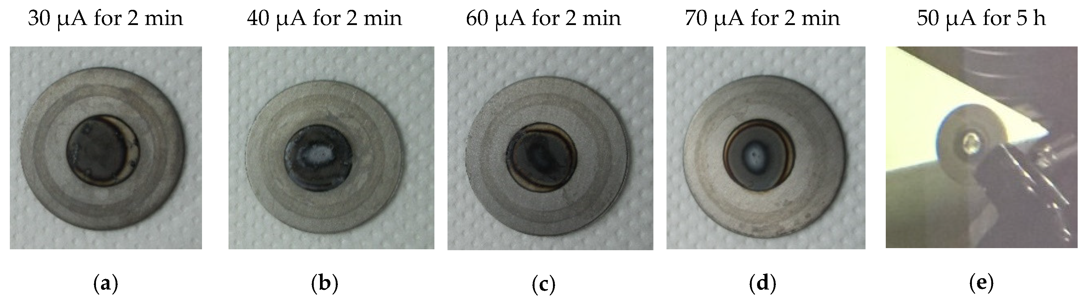
| Y-1 | 50 µm | Nb Ø24 × 0.5 mm | 12.7 MeV | 30 µA | 2 min | 0.5 kW/cm2 | Withstood (Figure 8a) |
| Y-2 | 50 µm | 12.7 MeV | 50 µA | 5 h | 0.8 kW/cm2 | Withstood | |
| Y-3 | 50 µm | 12.7 MeV | 40 µA | 2 min | 0.65 kW/cm2 | Withstood (Figure 8b) | |
| Y-4 | 50 µm | 12.7 MeV | 60 µA | 2 min | 1 kW/cm2 | Withstood (Figure 8c) | |
| Y-5 | 50 µm | 12.7 MeV | 70 µA | 2 min | 1.1 kW/cm2 | Withstood (Figure 8d) | |
| Y-7 | 70 µm | 12.7 MeV | 50 µA | 5 h | 0.8 kW/cm2 | Withstood (Figure 8e) |
| Y Thickness, µm | Cyclotron, Target | E, MeV | I, µA | t, h | Aexp 1, mCi | Atheor (Lit.) 2 mCi | Atheor (this work) 3 mCi | Lit. Ref. | |
|---|---|---|---|---|---|---|---|---|---|
| 50 | ACSI TR-19 | 12.7 | 50 | 5 | - | - | 41.0 | 0.16 | This work |
| 70 | 12.7 | 50 | 5 | - | - | 57.2 | 0.22 | ||
| 110 | ACSI TR-24, non-inclined target | 12.5 | 10 | 0.5 | 1.63 | 1.82 | 1.8 | 0.33 | [19] |
| 140 | 12.5 | 21 | 0.5 | 3.94 | 4.86 | 4.8 | 0.37 | ||
| 90 | 12.5 | 30 | 0.5 | 2.6 | 4.46 | 4.42 | 0.17 | ||
| 220 | 12.5 | 40 | 2 | 25.37 | 31.28 | 55.2 | 0.31 | ||
| 210 | 12.8 | 45 | 2 | 43.8 | 45.27 | 60.5 | 0.49 | ||
| 90 | 12.8 | 40 | 2 | 21.9 | 23.09 | 23.8 | 0.28 | ||
| 25 (700 eff. 5) | Philips AVF cyclotron, 1°–2° inclined target | 14 | 100 | 1 | 130 | - | 184.3 | 1.3 | [20] |
| 35 (1000 eff. 5) | 14 | 65–80 | 2–3 | 180–360 | - | 243.1–446.9 | 1.39–1.51 | [21] |
© 2019 by the authors. Licensee MDPI, Basel, Switzerland. This article is an open access article distributed under the terms and conditions of the Creative Commons Attribution (CC BY) license (http://creativecommons.org/licenses/by/4.0/).
Share and Cite
Skliarova, H.; Cisternino, S.; Cicoria, G.; Marengo, M.; Cazzola, E.; Gorgoni, G.; Palmieri, V. Medical Cyclotron Solid Target Preparation by Ultrathick Film Magnetron Sputtering Deposition. Instruments 2019, 3, 21. https://doi.org/10.3390/instruments3010021
Skliarova H, Cisternino S, Cicoria G, Marengo M, Cazzola E, Gorgoni G, Palmieri V. Medical Cyclotron Solid Target Preparation by Ultrathick Film Magnetron Sputtering Deposition. Instruments. 2019; 3(1):21. https://doi.org/10.3390/instruments3010021
Chicago/Turabian StyleSkliarova, Hanna, Sara Cisternino, Gianfranco Cicoria, Mario Marengo, Emiliano Cazzola, Giancarlo Gorgoni, and Vincenzo Palmieri. 2019. "Medical Cyclotron Solid Target Preparation by Ultrathick Film Magnetron Sputtering Deposition" Instruments 3, no. 1: 21. https://doi.org/10.3390/instruments3010021
APA StyleSkliarova, H., Cisternino, S., Cicoria, G., Marengo, M., Cazzola, E., Gorgoni, G., & Palmieri, V. (2019). Medical Cyclotron Solid Target Preparation by Ultrathick Film Magnetron Sputtering Deposition. Instruments, 3(1), 21. https://doi.org/10.3390/instruments3010021