1. Introduction
TOTEM [
1] is one of the experiments of the LHC, located at the Interaction Point 5 (IP5), together with the CMS experiment. The TOTEM experiment is focused on diffractive processes, which are characterized by the exchange of vacuum quantum numbers, resulting in a colorless interaction. From the kinematic point of view they are identified by the presence of large pseudorapidity gaps (pseudorapidity
is defined as
, where
is the polar angle between the direction of the particle w.r.t the beam direction), regions of space forbidden for the final state particles. In such processes, which include elastic scattering, single, double and central diffraction, one or both hadrons can survive the interaction and be scattered in the most forward region.
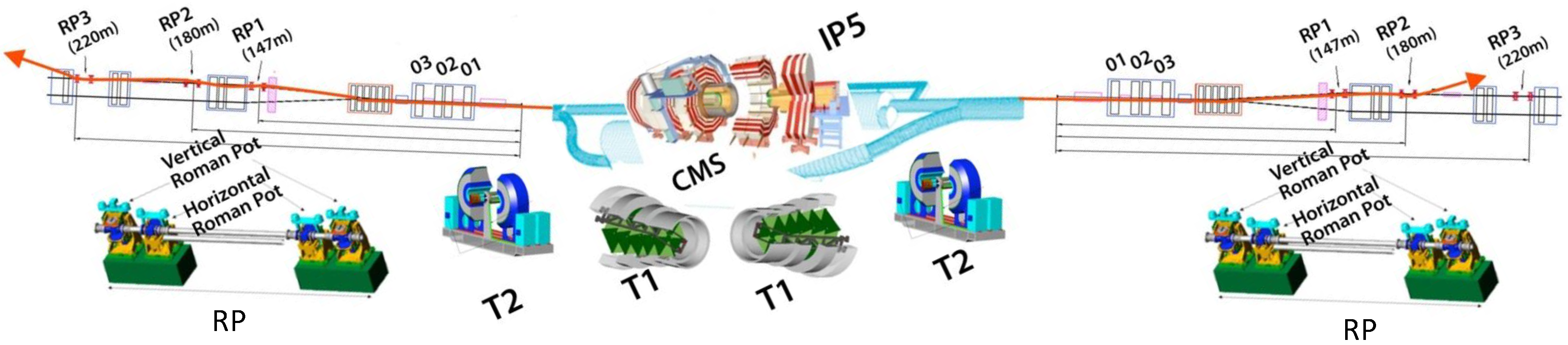
The TOTEM experimental setup was originally made by three different subsystems, two gas tracking detectors, T1 and T2, to tag and characterize inelastic events and the Roman Pot (RP) system to tag and measure the scattered protons in the very forward region (
Figure 1).
During the special run described in
Section 2, only the RP system, operated in conjunction with the CMS experiment, has been used. The RP is a secondary vacuum vessel, which can host different type of detectors, that can be moved into the primary vacuum of the machine through vacuum bellows. The detector can thus approach the beam down to a few millimeters, which allows to detect protons scattered down to a few microradians. Three RP units on each arm (one arm is one side of the detector w.r.t. the IP) are used for the special run (two for tracking and one for timing). A standard RP unit is formed by three RPs, two of them approaching the beam vertically and the third one horizontally, with an overlap region. Using two units separated by a few meters and equipped with tracker detectors it is possible to tag the proton and reconstruct its local angle. The vertical RP used for tracking are equipped with a set of 10 planes of edgeless planar silicon strip detectors, with a position resolution of ∼10
m. Once the position and angle of the proton track at the RP location is known, it is possible to compute the scattering angle at the IP by inverting the transport matrix, which describes the propagation of the proton through the magnetic field of the machine. To reduce the measurement uncertainties and to be able to detect protons with very low 4-momentum transfer (down to ∼10
−4 GeV
2), a special LHC optics (magnet configuration) is needed. The optics used is characterized by a large amplitude function
(from 90 m up to 2.5 km), larger than the one used for standard LHC runs. This grants a lower beam divergence at the collision point, the major source of systematics in the final measurements, at the expense of a lower luminosity. Distribution of protons in the RP depends on the LHC optics. With the LHC standard optics, mainly horizontal RPs are hit, while for
m, as in the special run, vertical RPs are used.
2. Special Run: Physics and Requirements
The capability of performing common data taking with the CMS experiment opens up the possibility of performing detailed studies of central diffractive (CD) processes [
2]. CD is characterized by two intact leading protons (eventually detected in the RP) and a rapidity-isolated system
X generated in the central region instrumented by CMS. The possibility of proton tagging leads to an exceptional background reduction. The mass and the transverse momentum of the central system, as well the rapidity gap, can be indeed predicted from the RP measurements and compared with the direct central system reconstruction done within CMS.
Of particular interest is the search for glueballs, pure bound gluon states predicted by QCD but not yet observed. Candidates predicted through QCD lattice computation have which perfectly match with the selection rules of CD processes, and have masses of few GeV (f0(1370), f0(1500), f0(1710) and f2(2220) as examples). The observed events have 1–4 GeV and un unprecedent low- (proton momentum loss). These conditions favour the observation of very purely gluon-gluon processes.
Studies of CD will be also carried out in standard high-luminosity LHC run, giving access to central masses in the range
TeV. Such studies will be done with the Precision Proton Spectrometer (CT-PPS) project, a common detector done by TOTEM and CMS, whose details and physics program can be found elsewhere [
3].
The physics program has been already exploited with a run performed in 2015 (∼0.4 pb
−1 collected), but more statistics are needed. To collect the needed statistics (∼5 pb
−1) in the time scheduled for the special run, the instantaneous luminosity with 90 m optics must be raised w.r.t. 2015. This has the drawback of an increased pile-up, represented by simultaneous
interactions in the same bunch crossing (the average number of collisions in 2015 was
). Due to their location, far away from the IP, the detectors installed in the RPs are not able to reconstruct the points of origin of the tagged protons with enough precision to assign them to the right
interaction vertex. To improve the proton-vertex association and perform a precise event reconstruction, two verticals pots for arm have been equipped with new very precise timing detectors (resolution
ps) to measure the protons time of arrival. This allows to reconstruct the longitudinal coordinate of the protons at the IP by measuring the difference of the proton arrival times in the two detector arms. Two sensor technologies have been exploited by the TOTEM collaboration, ultra-pure single crystal synthetic diamonds [
4,
5] and UltraFast Silicon Diode (UFSD) [
6]. Diamond sensors are currently used in the horizontal RPs, operating in standard optics LHC run, and are part of the CT-PPS detector. UFSD sensors are instead used in the vertical RPs for the 90 m special run.
3. UFSD Timing Sensors
UFSD are silicon sensors based on Low-Gain Avalanche Detectors (LGAD), optimized for timing measurements [
7]. The reduced sensor thickness (usually around ∼50
m) and the internal (VBIAS tuned) controlled gain (∼10) produce large signals with a large dV/dt, an essential feature to measure the particle arrival time accurately. Internal gain is achieved by adding an additional doping layer (with a high charge density ∼10
16/cm
3) at the
junction which, when fully depleted, generates the high field necessary to achieve charge multiplication. With the additional layer, a uniform electric field of the order ∼300 kV/cm is reached. The uniformity of the electric field is another key feature for the time resolution, removing the dependence of the charge collection time from the particle impact point.
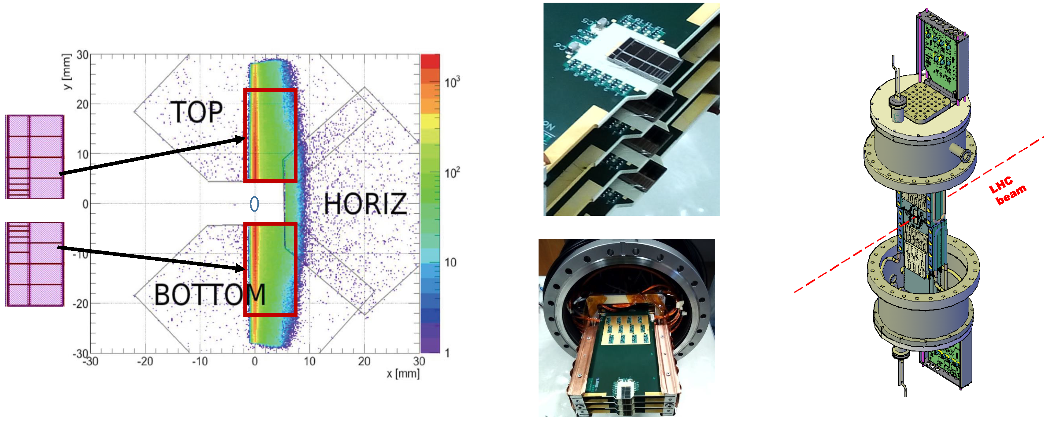
We use UFSD sensors, manufactured by CNM, specifically designed for the TOTEM experiment. The sensor has been divided into 12 pixels of different sizes, optimized to have the same occupancy in the region closer to the beam. In
Figure 2, the sensor layout has been superimposed to a simulation of the proton distribution in the RP area.
UFSD sensors are glued and bonded to the TOTEM hybrid board, which provides 12 dedicated amplification chains, one for each channel. The TOTEM hybrid [
4], originally designed for single crystal synthetic diamonds, was modified for the UFSD eliminating one of the three amplification stages. The amplification chain now only has three active elements (one BFP840ESD and two BFG425W BJT transistors). Results obtained in the test beam with the sensor prototypes have shown a time precision in the range 30–100 ps [
6]. The time precision scales, as expected, as a function of the pixel capacitance, which varies in the range 3–28 pF, almost linearly with the pixel area (coefficient ∼2pF/mm
2). Since each RP can host up to four hybrid boards (pictures of one detector stack can be seen in
Figure 2), the final resolution is expected to be better then 50 ps (and much better in the area close to the beam, where the smallest pads are placed) for all the pixels, and hence within the project specifications.
4. Sensor Readout
When performing time measurements we must take into account not only the intrinsic time resolution of the sensor, but also the uncertainties introduced during the signal digitization process. A standard approach is to use a discriminator coupled to a Time to Digital Converter (TDC). In this case, if a fixed threshold is used, an error (often referred to as
time walk) is introduced. Indeed, due to the statistical fluctuation of energy release in a thin detector, the same particle passing through two consecutive sensors will release a different energy. The output signal of the sensor where more energy was released will thus go above threshold before the other. The time walk can be the dominant source of uncertainty if not properly corrected, especially when large fluctuations of energy release are foreseen. The most common technique to mitigate the problem is represented by the Constant Fraction Discriminator (CFD), where the threshold of each signal is put at a certain percentage of its maximum. Another way to correct the time walk effect is to apply a time correction using the Time Over Threshold (TOT) measurement. TOT is the measurement of the time during which the signal remained above the threshold, and it is correlated to the collected charge. A description of such and other techniques can be found in [
8]. Also the TDC may play an important role, being the full system limited by its resolution.
A different approach to measuring the time is to perform a fast sampling of the signal in order to run a sophisticated offline reconstruction algorithm and obtain the best performance. A drawback of this method is that the sampler must have negligible dead time and be capable of high input rate. Not all samplers currently available can meet the rate requirements of an LHC detector. Moreover, this approach produces an increased data stream with respect to the TDC, where a maximum of one or two time measurements are performed on each waveform.
The solution adopted by the TOTEM collaboration for the signal digitization in the vertical RPs is based on the SAMpler for PICosecond time pick-off (SAMPIC) chip [
9]. The SAMPIC is a 16 channel ASIC, operating as a fast sampler of the analog input signals. The sampling frequency can be adjusted in the range 1–10 GSa/s. In the special run, the chip has been used at 7.8 GSa/s, which grants good stability and performance. The signal input range is ∼1 V (single-ended) with a 1.6 GHz bandwidth. UFSD sensors have a fast rise time of ∼0.7–1 ns, a SNR (Signal to Noise Ratio (SNR) is defined as the ratio between the signal amplitude and the noise RMS.) in the range 30–50 and a mean amplitude ∼400 mV, well matched by the SAMPIC characteristics.
Each SAMPIC channel is self-triggered by an internal discriminator on the input and digitized independently from the others. As a consequence, the channel readout order is random, without time sorting. All signals above threshold have to be read out from the chip, and only later a selection based on the central trigger can be performed.
When triggered, the channel can acquire up to 64 samples with a voltage resolution in the range 8–11 bit. The channel dead time (independent for each channel) depends on the chosen resolution, in the range 0.25–1.6 s. To keep the latency at minimum and reduce the data size, we decided to operate the SAMPIC at 8 bit resolution, the same resolution of a common oscilloscope, and to collect only 24 samples, with an overall acquisition window of 3.1 ns. Given the signal characteristics, this window allows sampling of the signal pedestal, which is very valuable for offline corrections, and of the full rising edge of the signal. In addition, the signal maximum is identified and recorded.
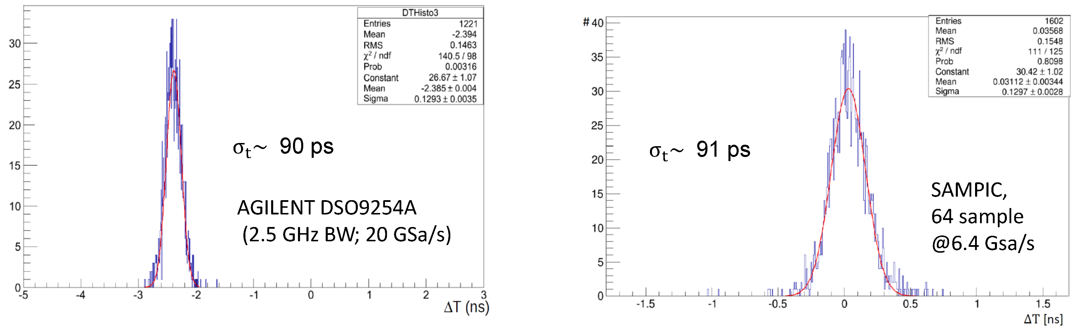
SAMPIC has been tested during the detector development, confirming no degradation of timing performance w.r.t. measurements where the oscilloscope is used. In 2015, the resolution of two diamond sensors placed inside the RP and operated during a standard LHC fill has been measured using the SAMPIC chip. The chip was successfully used with a stand-alone readout system. Time precision of each sensor has been computed as
, where
is the standard deviation of the distribution of the time difference measured between the two planes. The timing performance of the system was found equal to the one previously obtained in test beam with an high-end oscilloscope (see
Figure 3), where the same sensors had been used.
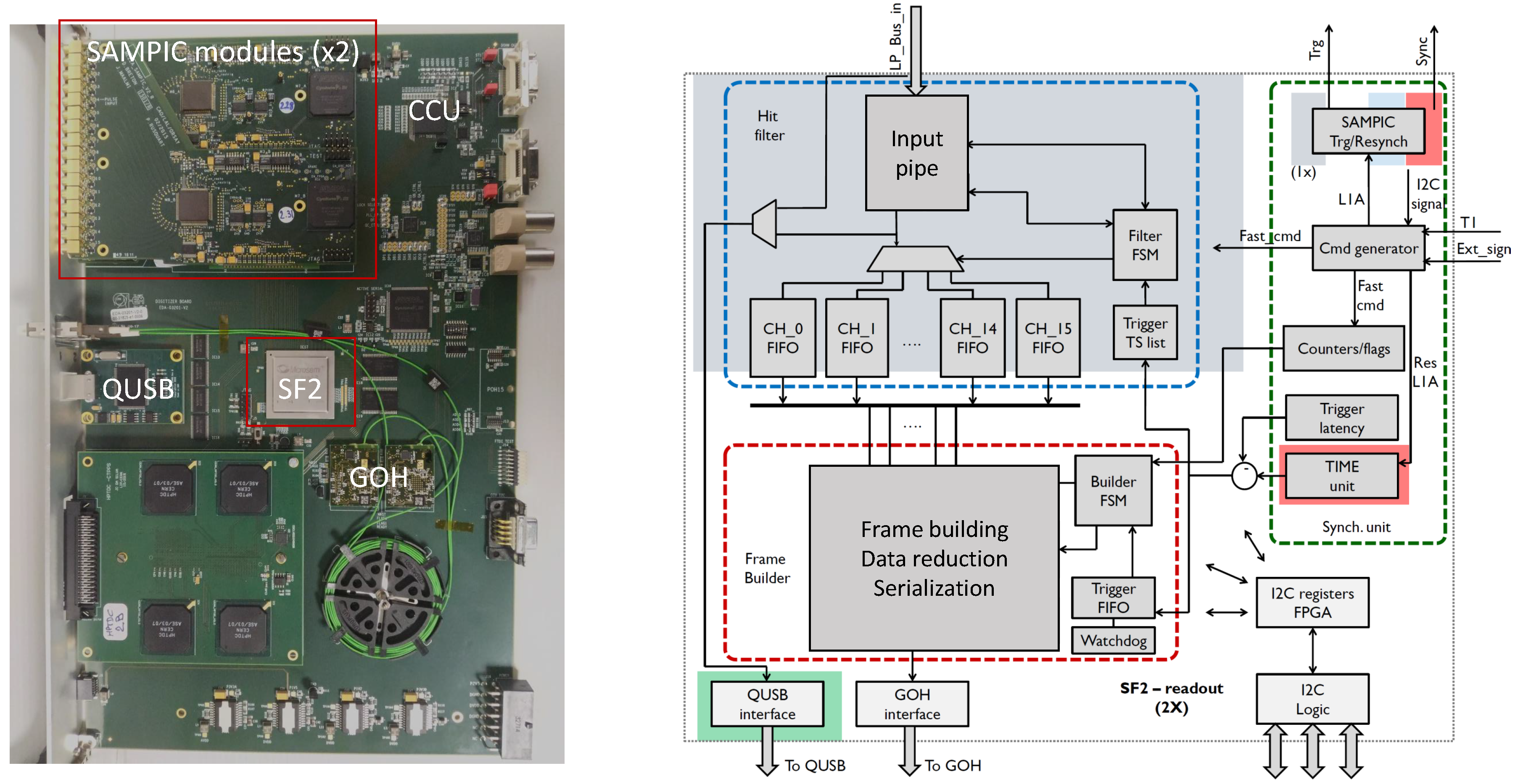
The SAMPIC chip is mounted on a SAMPIC mezzanine board developed in Saclay. Two SAMPIC mezzanines can be plugged into the Readout MotherBoard (RMB), a joint project of TOTEM and CMS, used also in the CT-PPS detector (see
Figure 4).
The board is based on the Microsemi SmartFusion2 (SF2) FPGA, a high performance FPGA protected against Single Event Upset (SEU) events. The RMB hosts multiple mezzanines and interfaces the SAMPIC chip with the TOTEM/CMS readout and control systems. The main components of the board are:
The DAQ requires that one and only one data frame is generated for each trigger (L1A), with a maximum L1A rate of ∼100 kHz. Moreover, data frames must be limited to ∼350 B and the system must be able to handle a trigger latency of 6
s. For the aforementioned characteristic of the SAMPIC chip, a special firmware has been designed. The firmware handles the configuration of the SAMPIC mezzanine and performs the packet (one packet contains the info about 1 digitized waveform) selection, the DAQ frame building and the data compression. The firmware for the data readout is composed of three main blocks (see
Figure 4 for a scheme):
The synchronization unit is the module which provides the synchronization of the SAMPIC data with the experiment DAQ. Fast commands (like L1A) arrive from the CCU encoded in a 3-bit LVDS transmission. The bits are decoded and L1A (among other signals) generated. For each L1A, a timestamp TS is created by subtracting the trigger latency (remotely controlled) from the trigger arrival time.
When a waveform is digitized in a SAMPIC, the relative data packet, which contains the channel number and timestamp, is sent to the FPGA. The packet is delayed by 10 s by an input pipeline to ensure that the eventual L1A has already arrived. Then a dedicated state machine checks the packet timestamp against all the TSs generated by the synchronization module and, if a correspondence is found, the SAMPIC channel number is extracted and the packet is sent to a FIFO dedicated to that channel. In this way, it is possible to achieve a first significant data reduction, measured to be of a factor 10. Moreover, since the packets coming from the same channel are time ordered, each channel FIFO contains time ordered data packets. At this stage, integrity checks are also performed by checking the number of words in the packet and the presence of the correct header and footer.
Next, the event frame is built. The builder module reads the first TS still waiting for building. After a minimum of 100 s from its arrival, the module collects all packets in the channel FIFOs with the matching timestamp and build the final frame. This building latency is needed to ensure that all packets generated by SAMPIC have been sent and received by the main FPGA. At this stage, a zero suppression is done, since only channels which have generated a packet are inserted into the event data stream. Further data reduction is achieved by compressing SAMPIC information. The frame is finally sent with the GOH to the DAQ system.
6. First Results
The detector and part of the readout electronics have been installed during the LHC winter shutdown 2018. Tests of the timing system have been successfully performed during the RP alignment (a special procedure to center the RP station w.r.t. the proton beam) and during the LHC luminosity rump-up, where an integrated luminosity of ∼13pb−1 was recorded. Moreover, the detector was operated during a low-energy and low-intensity run performed by the LHC: even though the beam optics was not the one foreseen for 90 m special run, all the systems have been validated (readout, slow control, firmware, ⋯).
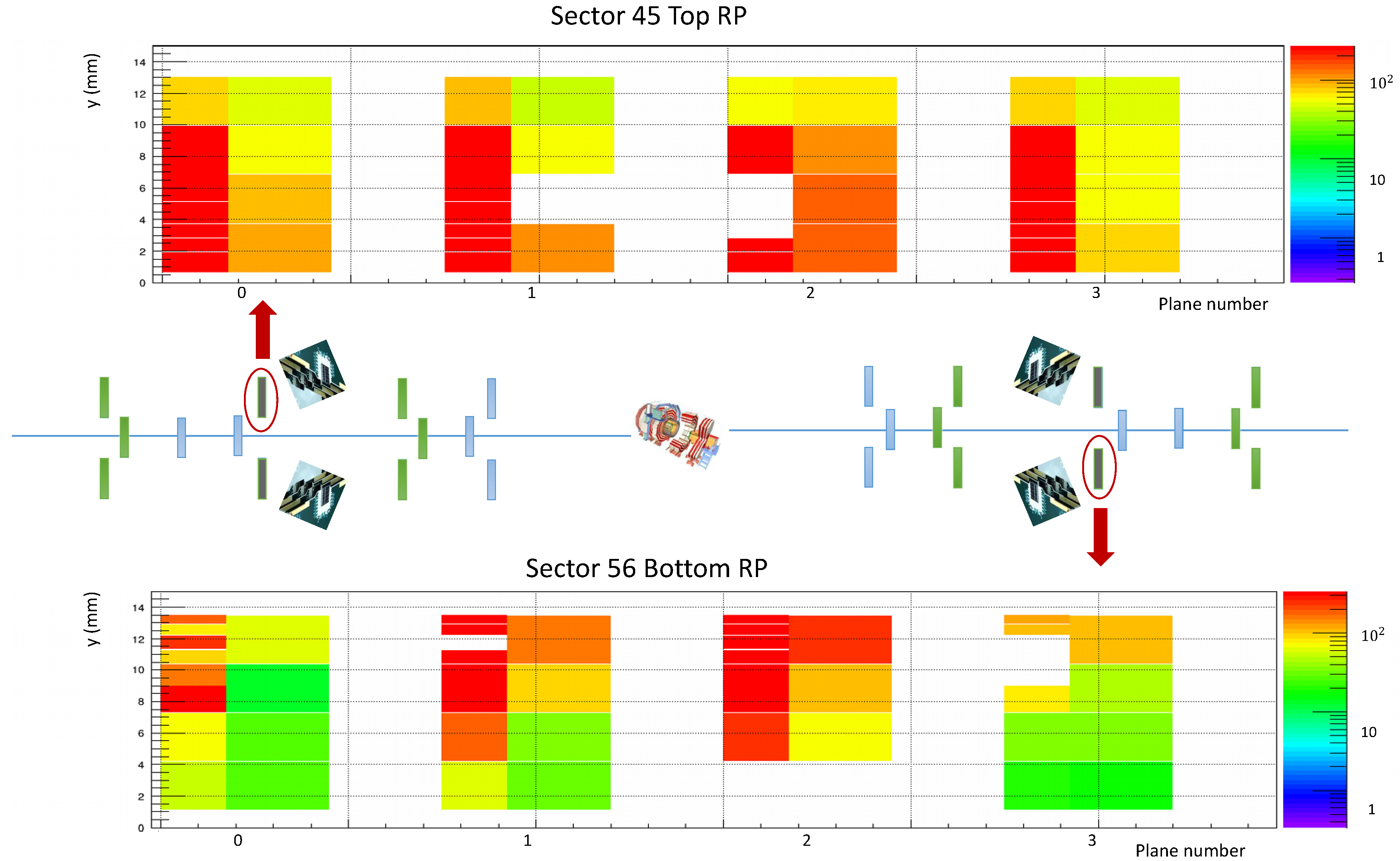
In
Figure 5, the sensors’ occupancy for two RPs is shown (only one “diagonal” was completely equipped at the time of the test). The test (done in April) was mainly focused on the electronics and firmware. Sensors were biased at ∼120 V (expected breakdown at 200 V) or less if the limit of 100
A was reached. A scan of the bias voltage was performed during the special run (data under analysis), with I-V curves generated for all planes to identify the breakdown voltages.
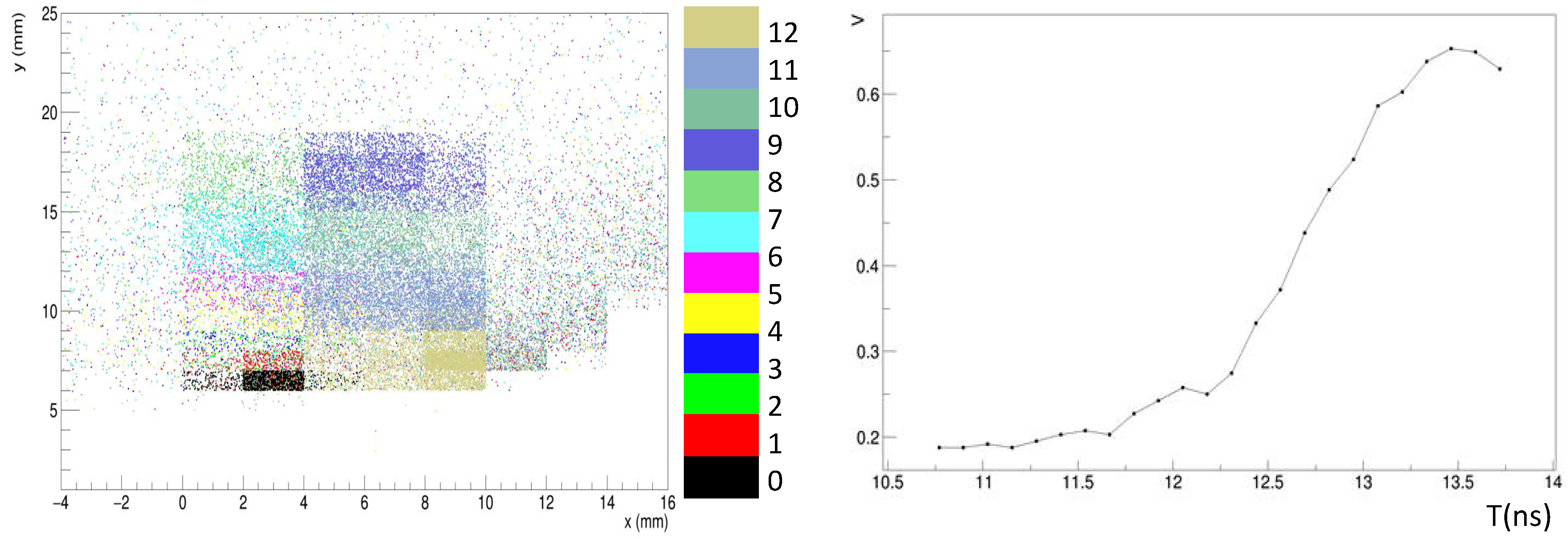
Acquired data has been analyzed together with the tracker data. A proton passing through the strip detector can be reconstructed with high precision and then it is possible to check if and where it was recorded from the timing detector. This technique, referred to as tomography, can be used to check detector mapping and efficiency and the sensors alignment w.r.t to the strips. In addition, the latency of the detector can be verified: if the detector has a wrong latency, the recorded tracks will have no spatial correlation with the one reconstructed in the tracker. In
Figure 6 (left) we report the tomography of one of the detection planes. In the histogram,
x-
y position of the point is given by the tracker reconstruction, while the color is given by the channel number of the timing system. If good mapping and latency is used, the layout of the should be visible, as seen in the figure. Finally, in
Figure 6 (right) an example of a waveform recorded with the timing system is shown. The waveform is reported without any calibration of the SAMPIC chip. The final result, after ADC and time calibrations, will be much smoother, enhancing the performances of the timing system.
No degradation is foreseen for radiation damage. The same type of sensors has been used in the CT-PPS project, where the proton flux is about two orders of magnitude grater. CT-PPS sensors showed radiation effects after several weeks of operation. Given the short duration of the special run (five days), no radiation effect was expected, and preliminary results seems to confirm this. During the time between installation and data taking, the stations were in a safe position, protected by the collimators.

