Abstract
We present the first implementation of an FPGA-based PUF that leverages the usually contradictory requirements of stability and response time. Many state-of-the-art implementations of PUFs are either slow with a low error rate, like the ring oscillator-PUF, or fast with a higher error rate, like the arbiter-PUF. The presented implementation of an eye-opening PUF uses the phase-integrating effect of a ring oscillator to realize the shortest possible response for the required stability of the readout. This principle also allows for new automatic detection of unstable bits based on counting the number of oscillations required until an arbitration is conducted. This first implementation of an eye-opening PUF reduces the bit error rate to a number under our measurement limits, while the readout time is simultaneously kept as low as ≤1.54 μs, with an average of 0.85 μs. In addition, environmental temperature changes are evaluated, and methods for limiting these effects are discussed.
1. Introduction
Security in electronic devices is a highly demanded requirement in many applications. To identify and protect intellectual property, electronic components, and systems from manipulations, counterfeiting, or other harm, physical unclonable functions (PUFs) have been proposed over the last two decades. They are memory-free low-power security primitives with the functionality to generate random but unique hardware fingerprints that can be used to identify hardware devices or for more advanced encryption applications like [1,2]. The PUF uniqueness only depends on small manufacturing variations, which make its responses ideally unclonable and unpredictable, even by the manufacturer. Beyond many other parameters [3,4], two important key requirements for PUFs are the stability of their response and short readout time.
PUFs have been proposed in various architectures, both for implementation as integrated circuits (ICs) [5,6,7,8] or on field-programmable gate arrays (FPGAs) [9,10,11,12,13]. Whereas IC-based PUFs obviously offer larger design space, FPGA-based designs offer other distinct advantages: the FPGA can be used both functionally and as source of entropy of the PUF by reprogramming, and FPGAs are intrinsically available in many state-of-the-art (SotA) electronic systems and are thus the more cost-effective solution in many applications.
A well-studied SotA implementation of an FPGA-based PUF is the arbiter-PUF, as indicated in Figure 1a [10,14]. The source of entropy is the delay difference regarding two parallel delay paths; the resulting phase shift of a triggered rising edge through the two paths is detected by an arbiter, effectively a D-flip-flop (D-FF) with one path entering its D-input and the other used as the clock input; the binary arbiter decision realizes a 1-bit output. The delay paths consist of switchable delay elements (SDEs), which can be swapped using multiplexers controlled by an input challenge vector. This alters the propagation delays depending on the challenge, which results in a challenge-dependent phase shift and arbiter response. Thus, a multitude of challenge–response pairs (CRPs) are generated, and this realizes a strong PUF [3]. Without the challenge and reconfiguration of the delay lines, every arbiter generates exactly one bit, and a weak PUF is realized. In [15], such a compact design was presented. Overall, the arbiter-PUF is very simple and has a fast response time, but it is very sensitive to noise as especially small phase shifts result in noisy unstable arbiter decisions. Moreover, when implemented as a strong PUF, it is also known for its easy attackability [16]. Ref. [10] reported a bit error rate (BER) of , while the evaluation time is in the picoseconds range.
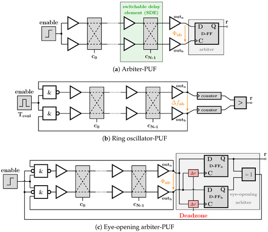
Figure 1.
Different PUF architectures. (a,b) show two SotA architectures, while (c) shows the EoA-PUF, which uses two competing ROs, like (b), whose oscillation is stopped when their phase difference exceeds an adjustable deadzone, leading to fast and stable decisions by the arbiter based on (a).
Another SotA FPGA-based PUF is the ring oscillator (RO)-PUF, as illustrated in Figure 1b [9,13,17]. Herein, the source of entropy is again a chain of delay elements, which by positive feedback result in an oscillation frequency of an RO; by comparing the oscillation frequencies of two (adjacent) ROs, a response bit is obtained. In [18], guidelines for the design of efficient RO-PUFs are provided. The SDEs of the ROs can also be reconfigured upon a challenge input vector generating CRPs [19]. RO-PUFs offer much better stability compared to arbiter-PUFs as they average the noise by their longer oscillation times. Unfortunately, this comes at the cost of longer readout times [20]. For example, Ref. [19] reduced the BER to be <, while one evaluation required . Also, they are prone to (even contactless) side-channel attacks due to the emission of RF spurs at their self-oscillation frequencies [20]. Another known variation of the RO-PUF is the TERO-PUF [21]. Instead of using two parallel ROs, they are connected in one chain to prevent locking phenomena. In [22], a compact variant, using just two inverters and D-latches, was proposed. Another common PUF approach regarding FPGAs was exploited with SRAM-based PUFs [23,24]. The bistable state of a non-written SRAM-cell decides on either 0 or 1 shortly after start-up. Unfortunately, the native SRAM PUF has a high error rate [23]. The bistable ring (BR)-PUF also evaluates the final state of several inverters arranged in a ring structure after release from a bistable state, like a power-up but offering a challenge input [11].
The instability in PUF responses due to noise, but also due to environmental changes like supply or temperature, has to be corrected for as, otherwise, authentication, fingerprint generation, or any cryptographic application would become impossible. Various methods are employed in the SotA to stabilize PUF responses. Bit-masking is used to store the locations of unstable bits and to blank them for reproducing the PUF response [5,6]; disadvantageously, in an enrollment phase, the unstable bits must first be found by (factory) measurement, and the positions of unstable bits can even change upon other environmental changes, such as temperature, which makes the task complex and costly. IC-based PUFs have also used hardening techniques, e.g., in IC-based SRAM PUFs [24]; this is not applicable in arbiter-, RO-, or generally in FPGA-PUFs. For the remaining PUF errors, digital error correction can be used [25,26]. The remaining random bit-flips of the PUF response are treated like noise in a communication channel, which are then corrected using helper data and error correction codes (ECCs). Obviously, the more errors that need to be corrected, the lower the code rate (number of useful bits for a given number of raw bits) and the more the complexity of the helper data and error correction algorithms increases. This helper data needs additional costly permanent memory, motivating a reduction in the amount of necessary data. Furthermore, the helper data can leak information about the secret PUF information to an attacker. Thus, secure schemes to store helper data have to be implemented, as investigated in [25,26,27].
Consequently, there is demand for more robust PUF architectures and improved PUF stabilization techniques, which ideally include the possibility to automatically detect unstable bits, to have an as ideal response of the PUF as possible before digital error correction. An idea to achieve this is the application of the so-called eye-opening arbiter (EoA)-PUF [28]. It operates as a mixture between the arbiter- and ring oscillator-PUFs and exploits phase difference integration by enabling oscillation until a predefined phase difference threshold (deadzone) is exceeded; this is illustrated in Figure 1c. Thus, it promises both fast and highly robust readouts.
In this paper, we present the first actual FPGA implementation of the EoA-PUF and validate its principles by measurement. Several tuning algorithms are proposed to remove routing-based response bias, which is—in contrast to IC-based implementations—an intrinsic non-ideality in FPGA-based designs. The paper is organized as follows: Section 2 reviews the basic operation of the EoA-PUF. Section 3 describes the FPGA-specific implementation of the EoA-PUF and a tuning method to overcome routing-induced bias. The PUF uniqueness is examined in Section 4, and, in Section 5, the adjustment of the deadzone and resulting BERs are investigated. Section 6 summarizes our work, and Section 7 concludes the paper.
2. Eye-Opening Arbiter-PUF
2.1. Review of Basic EoA-PUF
The idea of the EoA-PUF is depicted in Figure 1c. The source of entropy is the mismatch of two nominally identical delay lines. As in the arbiter-PUF, an input pulse propagates through both delay lines and an arbiter decides which of the two paths is faster and generates a PUF response bit. In contrast to an arbiter-PUF, the decision in the arbiter is thus only made if the phase difference exceeds a certain deadzone: in case of smaller phase differences , which are prone to noisy and thus unstable responses r, the intrinsic phase difference of the two delay lines is integrated over time by using RO-PUF features; the propagating pulse is fed back and an oscillation is started until a certain phase difference is exceeded; see Figure 2a. In other words, the conditions under which a decision will be made can be expressed as follows:

Figure 2.
Illustration of deadzone (red shaded area) in the EoA-PUF, preventing a decision while the impact of noise (illustrated by colored shade around the RO signals in green and blue) is high compared to the extracted entropy (left in (a)). After multiple rounds, the extracted entropy accumulated to a value larger than the impact of noise, and a decision can be reached.
Thus, the entire EoA-PUF consists of an RO-PUF-body with an arbiter-PUF decision-maker featuring an adjustable deadzone. The principle was first introduced for an eye-opening voltage-controlled oscillator-based comparator in [29] and was adopted for the EoA-PUF [13,28]. In addition to this core idea, Ref. [28] already noted that at least a single oscillation is necessary in the EoA-PUF since the required feedback paths in Figure 1c add to the statistically mismatched delay of the SDEs. Thus, a single propagation loops once through the delay lines, the feedback paths, and again the delay lines before the arbiter decides if the phase difference exceeds the deadzone. Therefore, the EoA-PUF achieves faster output than an SotA RO-PUF but will be slightly slower than an arbiter-PUF for stabilizing reasons.
While Ref. [28] focused on conceptual validation via Monte Carlo simulation on a circuit level, this work focuses on an actual implementation of the EoA-PUF on an FPGA and the challenges that arise in the design process. An FPGA was chosen as it is reprogrammable, allowing for fast prototyping and debugging. An XILINX ZYNQ-7010 on a zynq board (ZYBO) is used as a platform. Next, the FPGA-specific design choices, challenges, and implementation solutions are introduced.
2.2. Detailed Explanation of EoA Operation
As indicated in Figure 1c, the arbiter consists of two D-FFs, which are connected to the two ROs. The data input of D-FFa is connected with ROa, while the clock input is connected with ROb and vice versa for D-FFb. If, e.g., ROa is faster than ROb and the two rising edges thus appear with a large enough phase difference , D-FFb is first triggered and samples a 0, while D-FFa samples a 1 delayed by ; see Figure 2a. The subsequent XOR-gate in Figure 1c indicates a final decision by outputting a 1. Then, the value of D-FFa is chosen as PUF response. Thereby, due to the setup and hold time requirements () of the D-FFs, the phase difference of the two competing ROs has to be larger than ; otherwise, D-FFa also samples a 0 and the subsequent XOR outputs a 0, which indicates that no final decision is made yet. This requirement of forms an intrinsic deadzone, which was used in the original contribution of the eye-opening comparator as in [29], and also in the circuit simulations of the EoA-PUF in [28].
Using this deadzone is basically the core idea of the EoA-PUF as it comes with the advantage that—on the one hand—only large enough phase differences yield a PUF decision, which is good to avoid noisy and unstable decisions, and—on the other hand—the ROs only operate for just enough cycles to exceed this minimum required phase difference. Disadvantageously, the intrinsic deadzone of the arbiter varies over process, temperature, and supply. Moreover, some decisions might still be unstable due to noise if the intrinsic deadzone is too small. This raises the motivation to add additional and adjustable delays to the clock input of the D-FFs, and therewith increase the benefits of the deadzone. This is also indicated in Figure 1c: by adjusting the deadzone realized by the additional delays, the required phase difference for a decision can be changed. Increasing the deadzone results in even better stability, but at the cost of (slightly) longer evaluation times. As soon as is larger than the intrinsic plus the adjustable deadzone, the clock input of one D-FF is triggered before its D-input is set, and both D-FFs sample different values. Then, the XOR-gate outputs 1, stops the oscillation, and indicates a ready EoA-PUF response bit.
3. Eliminating Deterministic FPGA Routing Delays to Avoid EoA-PUF Bias
One challenging task in the FPGA design involves the routable wires pre-designed by the FPGA vendor, where each wire has a distinctly expected delay time. In Figure 3, this is indicated by the different lengths of the drawn wires.
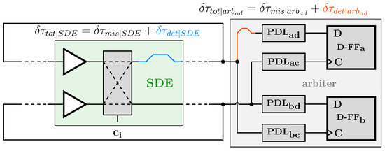
Figure 3.
Illustration of asymmetric wiring problem of an EoA-PUF on FPGA with a single switchable delay element (SDE) shown. The different lengths of the colored wires indicate the deterministic delay differences due to the pre-designed wiring matrices by the FPGA vendor. The shown PDLs are used for deadzone tuning; see Section 3.2.
The total delay difference consists of the mismatched induced random delay (i.e., the wanted source and entropy) and a deterministic part caused by asymmetric routing (which yields an unwanted bias in the response). In an ideal PUF, should be zero such that the resulting fingerprint, extracted from , is just related to . In the following, it is explained how the issue of unavoidable asymmetric routing is solved in the presented FPGA design of an EoA-PUF, first for the source of entropy and secondly for the arbiter itself.
3.1. Source of Entropy—Delay Element Design on FPGA
The entropy source of arbiter-, RO-, and EoA-PUFs consists of two identically routed paths of multiple SDEs, each featuring a nominally identical delay, which must only differ by mismatch, not deterministically by design. On FPGAs, this becomes especially challenging if cross-coupling (needed for strong PUFs and CRPs) is required. Thereby, it is practically impossible to find crossing wires with nominally identical and therefore symmetrical delay. To overcome this problem, the internal structure of FPGA Lookup Tables (LUTs) is used to switch two individual delay elements between two delay paths.
The implementaton of the crossing path of the SDE in Figure 1a, replicated in Figure 4a, is challenging on FPGAs. In [15,22], routing for cross-coupling in weak PUF-cells was presented, with almost identical delay. Nevertheless, for some wires, a remaining difference up to 48 ps was reported [22]. In an oscillating architecture like the EoA-PUF, such a difference would sum up with every oscillation, leading to a bias in the final response. In [10] the authors exploited internal delay differences of LUTs, arranged in two parallel paths, to design an arbiter-PUF without crossing connections in the entropy source. Therefore, inspired by the work of [10], the crossing paths are split into two identical parallel paths with two switchable delays each; see Figure 4b. Instead of swapping the delay elements between paths, each path swaps internally between two mismatched delay elements, which we will call half-SDEs (H-SDEs). Due to a following multiplexer, the challenge signal can still select which element is currently evaluated. As LUTs are used in FPGAs to implement buffers, the internal structure of these LUTs is adopted to simplify the hardware realization. This is visualized in Figure 4c. The input to the SDE selects the output value along paths through the LUT, while the challenge input, connected to the last multiplexer, selects which mismatched path to use. The LUTs, implementing the SDEs, can be connected identically in the parallel delay chains in Figure 1. The same principle was used in [10,20]. This comes with the additional advantage that the architecture can be easily ported to other FPGAs. Meanwhile, [22] (Table 1) reported that, by switching to a different FPGA, the expected delay of their symmetric routing increased by up to a factor of 43, rendering it an asymmetric switching; by using the proposed H-SDE-elements, such delay will alter the expected delay in both paths by the same amount, canceling them out. In order to validate this SDE implementation based on LUTs, 64 H-SDEs (see Figure 4c) were realized and connected as ROs at 40 different locations on an exemplary ZYNQ board. Then, challenge input vectors were applied to the H-SDEs, which differed only in one bit, to the vector they are compared with, and thus changed the internal delay path of a single element at a time. Then, the resulting mean frequencies were measured and the delay difference was extracted. The distribution of 10,000 evaluated measurements, each repeated 500 times to average out noise, is displayed in Figure 5. Two observations can be derived from these measurements. First, it can be seen that the change in a single challenge bit from 0 to 1 on average speeds up the propagation of a single RO. It seems reasonable to assume that this deterministic difference is caused by internal LUT layout asymmetries as the 7 ps is clearly a deterministic offset value. Process variation, on the other hand, is not likely to cause this deviation because the offset must be closer to 0 ps due to statics. However, since the manufacturer does not provide any information about the internal structure or layout, no final explanation can be found. Second, the delay difference by flipping a single challenge bit follows the expected Gaussian distribution. Using the provided statistic online tool from [30], the true mean value has to be determined between and 7.71 ps for a confidence interval of , with a true standard deviation between and 5.01 ps. For better readability, we assume a mean value of 7 ps in the rest of the paper.
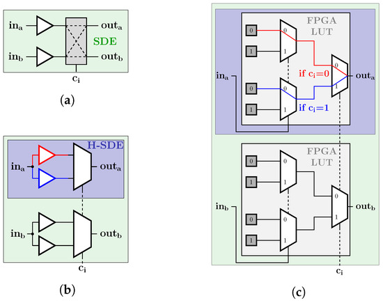
Figure 4.
Step-wise FPGA realization of the SDE. (a) shows the SDE used as source of entropy for all PUF implementations (see Figure 1). In (b), the symmetric paths of this SDE are split into two parallel H-SDE paths, avoiding the necessity to cross the paths. (c) illustrates the FPGA implementation of these H-SDEs via LUTs.

Figure 5.
Propagation delay differences of all evaluated LUT-SDEs when switching the challenge input form 0 to 1, with mean at ≈ ps in red.
The H-SDEs-element in Figure 4c used for the implementation of the SDEs is consequently well-suited as a source of entropy for PUF application because two such H-SDEs realizing a single SDE in Figure 4b are affected simultaneously by the deterministic mean shift, while only their random mismatch effectively changes the resulting phase difference. Thus, the identified problem of in Figure 3—consisting of a wanted mismatch-affected part as source of entropy overlain by a deterministic part by routing—is systematically solved by the SDE implementation in Figure 4.
3.2. Arbiter Routing Bias in FPGA-Based EoA-PUF
As indicated in Figure 3, the second source of deterministic routing delays is found in the arbiter. A systematic solution based on a separation into two parallel paths, as conducted for the SDEs (see Figure 4), is not applicable for the arbiter as both RO outputs must be fed to both D-FFs to form a deadzone. In the following, a programmable delay line (PDL)-based cancellation of the deterministic delays, due to unavoidable asymmetric routing on FPGAs, is proposed.
3.2.1. Implementation of PDLs Eliminating Arbiter Routing Bias
In order to solve the problem, the previous finding of the deterministic mean delay of the H-SDEs (see Figure 5) can be exploited. Multiple such cells can be concatenated to form a PDL with an n-bit input, where each bit is connected with the C-input of the corresponding H-SDEs, to select the desired delay. By adding a PDL into the paths from the RO outputs to the inputs of the D-FFs of the arbiter, PDLs can be added into all paths to the arbiter, and the influence of asymmetric routing can be minimized by proper tuning [10]. The internal implementation of a PDL is depicted in Figure 6.
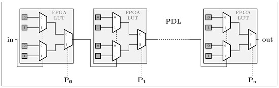
Figure 6.
Internal implementation of an n-bit PDL, consisting of n-concatenated H-SDEs.
As the delay cells of the PDL add not only a deterministic delay , which is required for the function of the PDL and the wanted compensation, but they also add a stochastic themselves, an appropriate tuning vector per PDL has to be found, which then achieves best cancellation of the deterministic delay due to asymmetric wiring by the adjusted delay of the PDLs in all paths. How the appropriate tuning vector for the PDLs can be determined is explained next.
3.2.2. PDL Tuning Approach
In [10], the authors found a fixed tuning set for all instances by evaluating the frequency of 1-responses, averaged over several PUF instances. However, due to the nature of PUFs, all routes are affected by individual delay variations that cannot be compensated by the same value, which would cause large bias in some PUFs. In [10] (Figure 10), this can be assumed by the large distribution of the quartiles in the plot, indicating that some instances have an occurrence of 1-responses of just . This problem was not further discussed in [10] and motivates an individual tuning per instance, which we present in the following.
In order to be able to tune the arbiter routing bias without affecting the source of entropy (i.e., the ROs), the FPGA design was extended: a symmetric calibration impulse can be triggered at the outputs of the ROs outa and outb in Figure 1c, which then propagates to the arbiter and allows to excite only the PDLs and arbiter. By observing the arbiter (D-FF) outputs upon this pulse, one can determine if one arbiter D-FF is triggered faster than the other, inducing a bias in the final response due to asymmetric propagation delays. This allows to adjust the PDLs accordingly. For this, an experiment was conducted on the used XILINX ZYNQ-7010.
In the following, the PDLs are named such that their first index refers to the D-FF referred to in Figure 3 (a or b), while the second index refers to the connected D-FF-port (c(lock) or d(ata)); i.e., PDLad is connected to the upper D-FFa’s data port. The EoA-PUF arbiter output is written as r . Thereby, r indicates that D-FFb was triggered first and r that it was triggered last. They indicate a deterministic bias in the arbiter if the symmetric calibration pulse is triggered. r and r appear if both D-FFs in the arbiter receive their D- and C-inputs simultaneously but either D before C or C before D, respectively. The goal of the PDL tuning is then to avoid a deterministic bias of the arbiter regarding either decision. Thus, the ideal tuning achieves a or decision upon the symmetric calibration pulse.
To speed up the tuning in the experiment, the PDL input vector was changed to unary-coded order; for all input bits, the same ps can be expected.
3.2.3. Experimental Results of PDL Tuning
In the first experiment, all possible combinations were evaluated for illustration purposes for one single arbiter instance. The results are shown in Figure 7. Therein, we show the arbiter D-FF decisions upon the symmetric calibration pulse as color code over the tuning of the PDLs on the x- and y-axis. Thereby, the “tuning level” of D-FFa is defined as , which is the unary-coded relative delay difference of D-FFa’s clock vs. data input. The same is defined for D-FFb and . Each combination of tuning levels was measured nine times, and the median was taken for evaluation. For tuning levels with multiple possible combinations, the averaged r of these combinations is plotted in Figure 7. Multiple combinations can occur, e.g., for .
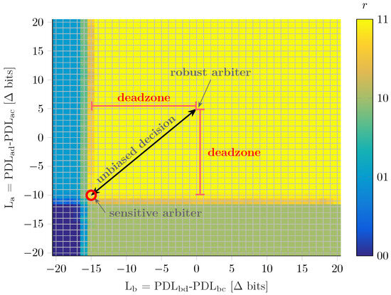
Figure 7.
Output of the D-FFs r = ⟨D-FFb⟩⟨D-FFa⟩ depending on all different tuning levels, which are the differences regarding unary-coded PDL-input vectors of the same D-FF. The green area is biased to , whereas the light blue area is biased to as response. The ideal tuning set for sensitive decisions is marked with a red circle. The black arrow indicates the tuning adjustment for unbiased decisions with increasing robustness. corresponds to an average of 7 ps as the PDLs are built with the H-SDE measured in Figure 5.
Four dedicated areas for r = 00/01/10/11 can be observed: when C- and D-inputs would arrive simultaneously, one would expect a output due to setup-time violations. In contrast, for no delay tuning La/b = 0, is the dominant output in this particular arbiter. The underlying reason is that the clock is deterministically routed slower than the data input. By making both La/b significantly lower, i.e., the data delayed vs. the clock, no D-FFa/b can sample the input impulse and we end in a output. By either making D-FFa or D-FFb significantly slower vs. the other, we allow one D-FF to sample the input impulse and the other not. This then results in a strong bias and outputs or , respectively. Looking closely, the -area is slightly narrower than the -area in this particularly measured arbiter. This originates from a random mismatch of the measured arbiter, either in the routing delays or the four PDLs, and thus looks different for every PUF instance.
After those observations, we need to decide which set of PDL tuning is optimally chosen. In the actual PUF, the two pulses arrive at the arbiter with a random mismatch-affected phase difference. Same (but opposite) phase difference should have equal probability to bring the D-FFa/b outputs to a final or decision and thus a 0 or 1 output of the PUF. This translates to an optimal tuning in the area but with equal distance to both the and bias areas, indicated by the arrow in Figure 7. The farther the tuning setting is from the and regions, the larger the input pulse’s random delay mismatch needs to be in order to force a decision by the arbiter. This means that the tuning setting makes it possible to chose between high sensitivity to small delay mismatches, corresponding to the tuning vector combination closest to all four areas, or tuning setting farther in the region, which results in more robust decisions; see Figure 7.
Consequently, the mightiness of the proposed EoA-PUF including the PDL tuning is that an unbiased PUF can be achieved where sensitivity can be traded against the robustness by setting the deadzone with the PDF-tuning.
3.2.4. Tuning Algorithm
Based on the previous findings, a fast tuning algorithm based on a binary search for edge detection was developed to determine the optimum combination for a sensitive arbiter (see Figure 7). The algorithm is provided in Algorithm 1. Each pulse is evaluated after a fixed time of 10 ns . Depending on the value of the optimum, this algorithm needs 14 to 140 evaluations for finding this tuning vector combination. With two clock-cycles per evaluation, this results in a total runtime of ≤2.8 μs for a 100 MHz clock. Therefore, it is possible to re-run the algorithm at every start-up of the system, which eliminates the need to permanently store helper data, in contrast to SotA implementations. This enables obtaining an individual unbiased routing to the arbiter, which creates the same basic conditions for all PUF instances. As the tuning architecture is separated from the source of entropy, these numbers stay true for a varying amount of challenge bits.
| Algorithm 1 Algorithm for finding the arbiter tuning. | ||
| while do | ||
| while do | ||
| ▹ search horizontal | ||
| end while | ||
| while do | ||
| ▹ search vertical | ||
| end while | ||
| if then | ▹ set next starting point | |
| else | ||
| end if | ||
| end while | ||
4. PUF Uniqueness Evaluation and Mean Frequency Tuning
Section 2 has introduced the EoA-PUF design, has derived ways to largely eliminate bias from deterministic routing mismatches in the SDEs by design and in the arbiter by PDL tuning, and has explained how the PDL can be further used to adjust the deadzone and compromise slower robust vs. faster noisy decisions. Next, we evaluate the PUF responses for uniformity, uniqueness, and randomness. A fixed tuning configuration per PUF instance is used for all evaluations, which was determined by the previously described algorithm.
Further metrics, such as NIST 800-90B and model-building resistance, have not been evaluated because a weak PUF implementation cannot extract enough bits to yield significant results. In addition, the applied metrics are used in other publications, allowing for direct comparison.
(1) The PUF uniformity is investigated by checking for an equal distribution of extracted bits observed when all challenges are applied to a single PUF instance. (2) Then, the uniqueness requirement has to be evaluated by comparing one PUF-bit derived from one challenge with all other PUF-bits derived from the same challenge with all PUF instances and FPGAs. Also, the extracted bits must be uncorrelated to fulfill randomness when (3) all challenges are applied to a single PUF-cell, or when (4) a single challenge is applied to all PUF instances. If one of these conditions is not fulfilled, an attacker can easily guess the response.
For evaluation, a total of 300 PUF instances were set up with challenge bits among 18 different FPGA boards. Hadamard codewords are used as challenges, which are linearly independent and therefore harden the PUF against machine learning attacks as the usable information from one codeword to guess the next is minimized [20,31]. Hadamard codewords have a length of powers of two and are constructed such that all codewords have the same Hamming distance (HD) to all other codewords, making them linearly independent. We excluded the all-one codeword such that all codewords have the same amount of ones and zeros, resulting in 63 different codewords. Applying these in a constant sequence to the PUF, each revealing one bit, results in a weak PUF with 63 bits and no external challenge input exposed to an attacker. An evaluation of the strong PUF configuration and its resistance to machine learning attacks motivates future work.
- (1) Validation of PUF Response Uniformity
In order to validate the above-mentioned uniformity requirement (1), the condition
is calculated for all bits extracted per PUF [32]. With , the amount of responses resulting in 1 is rated against the total amount of responses R. An equal distribution of 0 and 1 results in a = , while tending to correlates with a bias to 0/1 as all are either 0 or 1 independent of the challenge.
Since routing-induced bias was eliminated in the source of entropy by design and in the arbiter by tuning using the PDL approach, a = was expected. Surprisingly, during evaluation, a close to was measured in many PUF instances. To debug this unexpected behavior, counters were added to the RO outputs to measure their actual frequencies. A measured change in RO-frequencies over challenges for a single exemplary EoA-PUF instance is depicted in Figure 8.
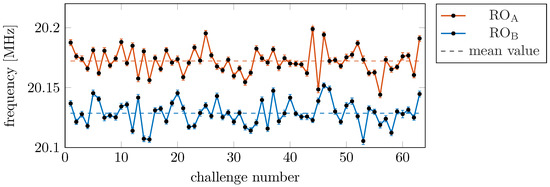
Figure 8.
Measured frequencies of both ROs of an exemplary PUF instance plotted over all challenges. The dashed lines are both mean frequencies.
As expected, each challenge vector changes the frequency of an individual RO in random directions with random magnitude. However, the difference in the mean frequencies of the two competing ROs, indicated by the dashed lines, is larger than the average frequency change caused by the challenge vector and thus the mismatch of individual SDEs. As the EoA-PUF response is derived from phase differences, which are integrated from the actual RO-frequencies, the EoA-PUF response is constant for all challenges in the shown exemplary PUF instance. Re-arranging and re-routing of the PUF did not help to reduce this bias in the challenged PUF response. Since the FPGA vendor does not provide detailed schematics of the internal architecture, it was also not possible to identify the reason for the residual bias in the ROs.
To overcome the partially too large mean frequency difference in ROA vs. ROB, an additional 20-bit PDL was added to the oscillating path of the ROs. By assigning these PDLs with different unary-coded vectors, the frequencies can be shifted, minimizing the frequency difference, similar to the arbiter tuning. The result for the same two ROs as in Figure 8 is shown in Figure 9. Due to the additional LUTs in the ROs, their mean frequencies decrease compared to Figure 8, but, most importantly, their random variation over different challenges is now distributed around the same mean. Even though an individual offset compensation must be found for every PUF instance, advantageously, these individual compensations remained stable over many evaluation cycles and can thus be stored as constant helper data. Since the PDL input vectors are thermometer-coded, a total of 10 bits are required per PUF instance. If these values are tampered with, the mean frequencies of the ROs will diverge again, which will result in a biased key and compromise the following application, similar to the insertion of a wrong key.
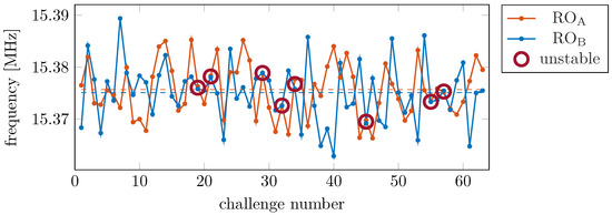
Figure 9.
Frequency plot of both ROs after tuning in hardware. The dashed lines represent the mean over all challenges per RO. The red circles mark unstable challenges with very little phase difference; see Section 5.
With this PDL-based RO-bias compensation, the was re-evaluated for all PUF instances over all CRPs. The resulting distribution is plotted in Figure 10 in blue. The mean is at with a standard deviation of ≈4%, which is comparable to the SotA [10,11,23]. Note that the choice of a length of the tuning-PDL depends on the expected variation in the employed FPGA and its LUTs. During our experiments, we evaluated varying lengths of tuning-PDLs and 20 bits was found to be suitable to tune all evaluated PUF instances. Changing the FPGA type would either require vendor information of statistical variation or a re-evaluation by experiment.

Figure 10.
Distribution of the uniformity evaluated by in blue, with a mean of and a standard deviation of , and the uniqueness evaluated by inter-Hamming distance (HDinter) in orange, with a mean of 50% and a standard deviation of 0.2%. For both, an ideal value of 50% would show a perfect distribution of the extracted bits.
- (2) Validation of PUF Response Uniqueness
After removing the bias in the individual PUF instance, the above-introduced uniqueness requirement (2) is evaluated by computing the HDinter [3,11]
HDinter generally calculates for each bit of a vector with length N the relative HD to all other bits in the vector. An HDinter close to indicates a unique distribution of the underlying bits, while HDinter close to indicates that all bits result in the same response. HDinter was then calculated by comparing every bit of a PUF instance with all other bits extracted with the same challenge of all other PUF instances, and this again along all FPGAs. The resulting distribution is plotted in orange in Figure 10. The mean value is with a standard deviation of , which fulfills the uniqueness requirement.
- (3) and (4) Validation of Uncorrelated PUF Responses
To validate the earlier listed requirements of uncorrelated PUF responses (3) and (4), the correlation coefficient of every PUF to all other PUFs is evaluated. Thereby, the correlation coefficient ranges between and represents the relation of two vectors: a value of implies identity or inversion, while non-related vectors have a correlation coefficient of 0. The distributions of the correlation coefficients of (3) all CRPs on a single PUF instance and (4) all PUF instances per single challenge are plotted in Figure 11. Both are arranged around 0.
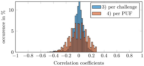
Figure 11.
Distribution of correlation coefficients, indicating the relation to other responses. The correlation coefficents of all CRPs per PUF instance are plotted in orange. The correlation coefficients of all PUF responses per challenge are plotted in blue. A value of 0 means that no correlation is present.
Concluding, the presented EoA-PUF implementation on FPGA can be stated to be unique and bias-free.
5. PUF Stability Evaluation and Automatic Detection of Unstable Bits
After having evaluated the uniqueness, the stability of the PUF responses over noise and environmental conditions is assessed. As discussed in Section 2, the distinct advantage of the EoA-PUF is the deadzone, which enables making arbiter decisions as soon as the arbiter/RO phase difference is large enough and thus stable to be decided. Moreover, as discussed with Figure 7, the PDLs used for arbiter bias tuning also allows to trade robustness in the arbiter decision vs. number of required RO oscillations by adjusting the deadzone. This is as the stability of a single PUF instance’s readout depends on the phase difference seen by the arbiter at the time of decision-making. Since small have a high chance to be influenced by noise, a larger deadzone makes this decision more robust.
As seen in Figure 7, the PDLs should tune the arbiter along the unbiased decision line, close to the switching region for sensitive or farther away for robust decisions. PDLac and PDLbc were used to tune this sensitivity against robustness, whereas PDLad and PDLbd were then used to set the deadzone along the unbiased decision line. As the PDLs for arbiter tuning are limited to 20 bits in unary code (see Section 3.2), 21 different deadzones can be adjusted and are considered in the following. For simplicity, we call this a deadzone configuration dz. For example, a dz of 2 bits sets the inputs of two H-SDEs in PDLad and PDLbd to 1, while the others are set to 0. Based on the average delay per H-SDE, each bit of the deadzone configuration will increase the deadzone by ps ps as the deadzone covers the negative and positive phase differences (see Figure 2).
5.1. Stability Evaluation
To evaluate the robustness of PUF readouts, each challenge is applied times to each PUF instance and then compared to a reference response Rref, for which we have chosen the median of all readouts at the largest deadzone. The stability is evaluated by computing the error rate via the intra-Hamming distance (HDintra)
for each CRP [3,11]. An HDintra of 0% means that all readouts were the same, whereas an HDintra of 100% means all readouts differ from the reference. The HDintra, averaged over all challenges, is plotted over varying dz in Figure 12 as blue line. If only the intrinsic deadzone of the arbiter is used and no additional deadzone () is adjusted by the PDLs, the HDintra is ≈10%. For an increasing deadzone by PDL, an HDintra of ≈2% can be achieved, but not less.
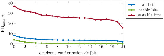
Figure 12.
Averaged error rate of PUFs for varying deadzone steps. The red line shows the blanked bits, while the green line represents the usable ones. In the blue line, all are combined. As the deadzone is adjusted with PDLs based on H-SDE, the average delay per deadzone configuration bit is ps = 14 ps.
Close investigation revealed that the HDintra was largely dominated by a limited number of very unstable bits on a limited number of PUF instances. Such unstable bits are highlighted for the exemplarily shown PUF instance in Figure 9 with red circles. There, it is obviously seen that ROA and ROB have almost identical frequencies for some challenges and thus remain indistinguishable for a long time. The experiment on this particular instance revealed that their frequency difference is ≤ with a standard deviation between and . For such challenges, the impact of compared to noise is very small. For reliable bit extraction, a large deadzone would be required together with a very large evaluation time to allow the tiny frequency difference to be integrated to a sufficiently large phase difference.
Hence, such unstable bits can be blanked to exclude them from the final key. Blanking is a known technique from the SotA [5,6], and, usually, the unstable bits, which need to be blanked, have to be found by time-consuming repetitive measurements. The unique feature of the EoA-PUF is the possible auto-detection of unstable bits, which will be explained in more detail in Section 5.2. After blanking of the unstable bits, the averaged error rate of all PUFs decreased to < when using the largest , which is shown in Figure 12 with the green solid line. Also, the much larger error rate of the unstable bits is shown in red for completeness’ sake. In addition, Figure 13 shows the relation of stable and unstable bits per FPGA-board. As can be seen, a minimum of of the bits are stable per evaluated FPGA.
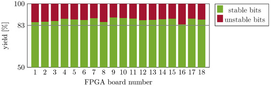
Figure 13.
Relative amounts of stable and unstable bits per FPGA board. The amount of stable bits is >83% per board.
For other than the largest deadzone, it can be seen in Figure 12 that the error rate decreases with increasing . With a deadzone configuration greater than s, the error rate starts flattening. This can be explained by the fact that the minimal required phase difference to decide is already significantly larger than the influence of noise, so any further increase in the deadzone brings only small improvements. This is comparable with the findings of [9,17], where RO-PUFs were investigated and where it was found that, after a certain evaluation time, no more improvements in stability could be seen.
Nevertheless, the maximum deadzone configuration of s was used for all further investigations as this value resulted in the lowest error rate.
5.2. Intrinsic Autodetection of Unstable Bits in EoA-PUF
Blanking of unstable bits is a commonly seen technique in PUF design in order to improve PUF robustness [5,33,34]. This usually requires many repetitive measurements of all PUF instances and challenges and subsequently, after the statistical detection of (too) unstable responses, an exclusion of unstable bits. Detection of unstable bits is often conducted externally, requiring the responses to be shifted off-chip, which can leak the secret information through an unprotected port. Since repetitive measurements are time-consuming and detection based on statistical analysis complex, an onboard method that requires only a limited number of measurements without prior statistical knowledge would be advantageous. To the authors’ knowledge, both requirements are met by the unique features of the EoA-PUF as it allows auto-detection of unstable PUF-bits, which is explained in the following.
In the presented EoA-PUF architecture, RO pairs with small frequency differences must oscillate more frequently than RO pairs with large frequency differences to generate a large enough phase difference to leave the dead zone and thus cause the arbiter to make a decision. This explains the auto-detection of unstable bits; i.e., if a decision takes too long, it is rather considered unstable.
To evaluate this, we examined the number of required RO oscillations until the arbiter makes a decision. This is plotted over adjusted arbiter deadzones in Figure 14; thereby, we separate prior found unstable responses from stable responses. It is seen that the number of required oscillations provides a very clear indication if a response was rather stable or not. This is an intrinsic property and advantage of the eye-opening effect of the arbiter and does not rely on the applied arbiter tuning.
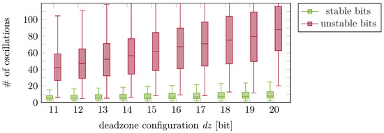
Figure 14.
Number of oscillations required to exceed the deadzone and trigger a decision by the arbiter, plotted over PDL-tuned arbiter, based on H-SDE; the average delay per additional deadzone configuration bit is ps = 14 ps. Shown for “stable” and “unstable” bits.
By defining a threshold , all challenges that oscillated longer than until a final decision was made can be blanked in an initializing step. This can be repeated at every system start-up, making non-volatile memory to permanently store a blanking matrix obsolete, which is an improvement compared to the SotA. Further, it is not necessary to move the secret information, i.e., the PUF-bit responses, off the device for stability assessment. Although not evaluated in this work, these findings are also true for strong PUF implementations. Challenges leading to reasonable phase difference will lead to fast and stable results, while the remaining will be detected as unstable, without the need to classify every challenge in advance.
One could argue that such an auto-detection of unstable bits should also be possible in other oscillating PUFs like the TERO-PUF. The TERO-PUF is enabled for a fixed amount of time. Stable bits collapse into a stable state during this evaluation, while unstable ones do not; this should theoretically be detectable. The difference to the proposed EoA-PUF is that the latter has the XOR-gate output as an intrinsic signal, indicating if a decision was made. For the TERO-PUF, an external analysis of the outputs must be performed. Just adding an XOR-gate to the TERO-PUF would also not solve the issue as it would already recognize small noise-induced differences. Additional noise-suppressing hardware would be necessary, which results in the idea of the eye-opening arbiter, as presented in this work.
5.3. Further Use of the Reliability Information of Bit Decisions in the EoA-PUF
In addition to the possibility to use the oscillation length as an indication for unstable bits and thus automatic mask building, the same information can be used for other advantages, like the reliability information for a soft decision error correction code presented in [26]. Also, readouts that are not blanked as unstable bits but by chance exceed in a single readout can be identified and re-sampled for, e.g., majority decision.
The number of oscillations can also be related to a maximum evaluation time for a response as the mean frequency of the RO is known. These frequencies vary from 13.16 MHz to 17.46 MHz for different PUF instances. Figure 14 shows that the lower bound for the required number of oscillations is 20 for unstable bits with a deadzone of 20 bits, which is expected to have the longest evaluation time. By choosing an upper bound of allowed oscillations for a decision to be and setting the slowest mean RO oscillation frequency to = 13 MHz, a maximum evaluation time of can be calculated by s. For , the mean amount of oscillations can be used to approximate an average evaluation time of s.
5.4. Stability Against Temperature Variations
Environmental influences are a well-known non-ideality for all ICs and FPGA designs and can change the extracted PUF responses. Therefore, the influence of temperature changes on the EoA PUF is investigated. Please note that the used ZYBO allows no direct control of the FPGA power supply; thus, voltage variations are not investigated. Four FPGAs were evaluated at varying temperatures from °C to °C in steps of °C. This range was chosen to not damage the other components on the used ZYBO. The deadzone configuration was set to the maximum value of 20 bits, which corresponds to an expected deadzone of ps = 280 ps and results in maximum stable bits. The midpoint of the evaluated temperature range was taken as a reference temperature at °C. At every temperature step, an arbiter tuning (see Section 3.2) was conducted at start-up. Thereafter, all PUFs were evaluated 250 times and the resulting responses compared to the golden response at the reference temperature using Equation (4). The resulting HDintra is plotted in Figure 15 as green line for the EoA PUF. For the sake of comparability, a conventional SotA RO-PUF is implemented and evaluated on the same FPGAs. This is completed by disabling the arbitration signal and enabling the ROs for evaluation time; this value was extrapolated from the results of [17], who used the same type of FPGA for RO-PUFs. By comparing the amount of oscillations of both ROs, a response bit was derived. This bit was compared to the median of all responses. The resulting HDintra for this RO PUF is plotted as blue line in Figure 15. The general profile over temperature is similar, but the RO-PUF shows a distinct shift to worse stability when compared to the EoA-configuration. As the same hardware setup was used for both configurations, platform-dependent reasons for this shift can be excluded. Further investigations showed that some RO pairs just differed in a few oscillations after the evaluation time of and therefore are sensitive to noise. Since a pure RO-PUF implementation does not have an in-built detection of unstable bits, these bits cannot be blanked at runtime but have to be determined in a post-processing step.
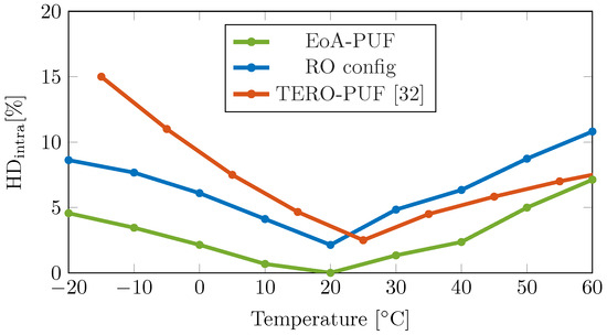
Figure 15.
Error rates of different FPGA-PUF implementations for varying environmental temperatures. For a better comparison, the difference from the reference temperature comprises the x-axis. The data from [35] were estimated from the supplied graph. Please note that Ref. [35] used °C as reference room temperature, while we used °C lab temperature as reference.
For further comparison of temperature dependency, results reported in the SotA for other FPGA designs are also considered. Even though the authors in [10] presented a PDL-based arbiter-PUF on an FPGA and reported their error rate over the temperature range from to °C as up to , no detailed data was provided and thus no graph was plotted. In [35], a TERO-PUF was implemented on FPGA. The TERO-PUF consists of two ROs connected in one chain, running until a stable state is reached. The best-case error rate over temperature provided in [35] is plotted as orange line in Figure 15, which shows a higher error rate at reference temperature than the presented EoA implementation of this work. In addition, the slope of the error rate is two times higher for negative temperature changes. For positive temperature changes, the slope seems to decrease. As the authors of [35] did not address this behavior, it might also be a board-specific second-order effect, making further elaboration or comparison difficult.
In [9], the authors evaluated a short RO-PUF, consisting of three LUTs, for temperature variations from 5 to °C. From their data, the authors used a linear approximation of the error variation with temperature and stated for a change of °C. As the authors did not state an error rate at reference temperature, but only a change, no overall comparison can be made. Nevertheless, it can be stated that the slope of of the EoA PUF and the approximation from [9] are quite similar for small temperature changes but diverge for larger temperature changes. As the authors in [9] already stated, the changes in frequency (and therefore also phase difference) on FPGAs are non-linear over temperature; Ref. [36] showed that a third-order polynomial provides a better fit. Therefore, the linear approximation in [9] is not accurate for large temperature differences and not suitable for comparison to the course of the measured results in Figure 15.
In summary, the unique features of the proposed EoA-PUF design allow very low error rates at reference temperatures, which is based on the calibration using the PDLs as well as the automatic detection of unstable bits. Even though the positions of unstable bits and the ideal calibration/tuning setting can partially change at other temperatures, the temperature dependency of the error rate is quite comparable with other SotA implementations. Still, the features of calibration and auto-detection of unstable bits can be further exploited to reduce the bit error rate over temperature, which will be shown next.
5.5. Further Temperature Compensation
In the previous evaluation, all tuning values were kept constant. However, in the following, the possibilities of PDL-based tuning as well as the unique property of the auto-detection of unstable bits in the proposed EoA PUF are exploited with the goal to further reduce the error rate over temperature.
5.5.1. Offset Re-Calibration at Different Temperatures
A temperature variation causes the mean oscillation frequencies of the two employed ROs in the EoA PUF to shift with slightly different magnitudes [9,36]. This can be seen in Figure 16 for one exemplary RO pair. Thus, the employed mean frequency offset compensation at a single reference temperature (see Section 4) becomes less effective for large temperature changes. For better visibility, the frequency difference of both ROs is plotted in Figure 16b. The overall drift dominates the influence of the challenge, causing some extracted bits to flip.
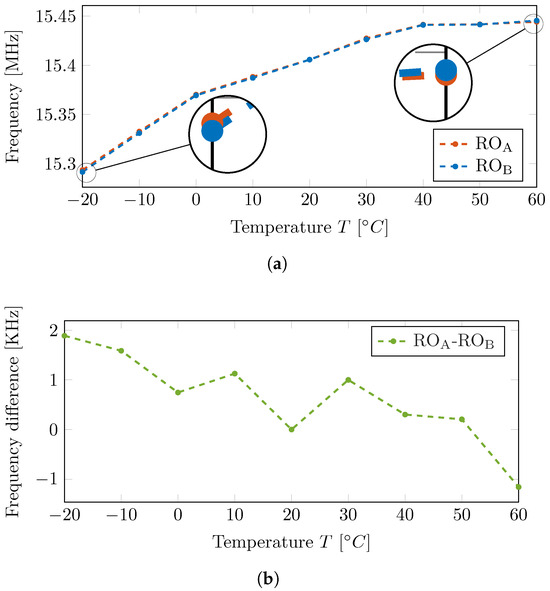
Figure 16.
Temperature-dependent mean frequency change of one exemplary RO pair. (a) Absolute frequency change over varying environmental temperatures. (b) Frequency difference of both ROs over varying environmental temperatures.
Since all PDLs used for offset compensation are affected by temperature in slightly different ways, no general rate of change for the offset tuning can be found. Nonetheless, this shift in mean frequency offset and thus its tuning could occur at more than one calibration point. For illustration, the nine evaluated temperatures were divided into three parts, each covering three temperatures. Next, the offset compensation, as explained throughout Section 4, was re-calculated at the midpoint of each part, i.e., at °C, °C, and °C. The resulting error rate for the whole temperature range from °C to °C is plotted as the red line in Figure 17. The three calibration regions, in which the 3 sets of calibration data were used, are indicated by the vertical dashed lines.
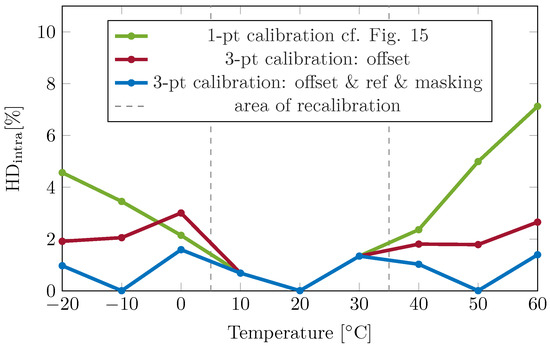
Figure 17.
Temperature-dependent error rate of the presented EoA-PUF implementation, in green, compared to temperature-compensating approaches.
5.5.2. Re-Sampling the Reference and Stability
Throughout the prior sections, the EoA PUF has not only been calibrated for an offset of the two ROs’ mean frequencies but also (auto-detected) unstable bits were eliminated from the response. Thus, it is obvious that only an offset re-calibration over temperature cannot solve all the additional bit errors over temperature variations.
After the re-calibrated mean frequency drift, the different tuning vectors may result in minor changes in individual pairs and bit responses and thus change some prior unstable bits to become stable and vice versa. Therefore, the EoA-PUF intrinsic auto-detection of unstable bits was also used at all three calibration points to determine blanked bits for each evaluated region. Thereafter, the reference response (determined at °C) was updated at the other two temperatures as the original reference might be invalid for bits that were unstable and became stable with changing temperature. This lowered the error rate at all three calibration points to almost zero, as can be seen in Figure 17 as blue curve. The evaluated temperatures next to the calibration points have a remaining error of around , which can be expected as the offset calibration, masking, and reference response change with temperature and cause some bits to flip. In consequence, to reduce the overall error rate of the EoA-PUF, more than one calibration point can be selected to re-calibrate the new mean oscillation frequencies of the two challenged ROs and to auto-detect the unstable bits over a wider temperature range. The amount of stable bits stays constant over all calibration points (see Figure 13), but detected unstable bits vary in position. On average, the amount of stable bits over all calibration points is reduced by compared to the reference temperature. Although no voltage variation can be conducted due to the lack of direct access to the power supply, it can be expected that constant voltage drops, which change the operation point, can also be compensated by this approach. Temporary fluctuations in the power supply can be seen as additional noise and eliminated by increasing the deadzone.
In summary, the EoA-PUF—when calibrated only at one temperature—behaves as good as or even better than SotA implementations over temperature changes, while it provides a faster readout compared to SotA RO-PUFs. In addition, using some of its unique features, like calibration and auto-detection of unstable bits, the temperature dependency can be minimized at distinct temperatures and thus overall flattened over a wide temperature range.
6. Discussion and Comparison
PUFs are used in different configurations and applications with different requirements. Applications using a PUF for constant key generation lack the need of a challenge input and render into a weak PUF, whereas authentication applications require strong PUFs with an accessible challenge input. After a short recapitulation of the final architecture, the tuning effort as well as the attackability of the EoA-PUF in both configurations are shortly discussed in the following.
6.1. Final Architecture
In the final design, two parallel ROs consisting of one NAND, sixty-three H-SDEs as the source of entropy, and twenty H-SDEs for offset calibration were used. In addition, four arbiter tuning PDLs, each consisting of twenty H-SDEs, were implemented. These are connected to the source of entropy by a selection LUT, which switches between tuning and normal operation mode. The arbiter tuning PDLs are also used to adjust the desired deadzone. An eye-opening arbiter is implemented to finally evaluate the phase difference caused by the source of entropy. Hadamard codewords are applied to render the PUF into a weak PUF configuration. This required an additional 20-bit PDL to minimize the frequency offset. As four LUTs fit into one slice, this results in a total consumption of 65 FPGA slices. Since Hadamard codewords have a length of powers of two, the challenge input was not increased further as, otherwise, the design would have been implemented over different slice types and clock regions on the used FPGA. An overview of the final design is depicted in Figure 18.
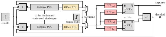
Figure 18.
Implementation of the final FPGA EoA-PUF design. The PDLs for offset tuning are depicted in yellow, while the red PDLs are used for arbiter tuning and adjusting the deadzone. The output decided indicates if a final decision is made, while response returns the response bit. The two multiplexers allow switching between tuning mode and normal operation.
6.2. Tuning Effort—Weak Versus Strong PUF
For weak and strong PUFs, any implementation-specific bias in the response must be removed. Asymmetric routing from the entropy source to the arbiter causes such bias for both PUF-types, which are compensated in the presented work by the addition of tuning PDLs and a newly proposed tuning algorithm.
With the implemented challenge input, the amount of extracted bits per PUF instance was increased, which also enables a future extension to a strong PUF. However, in the presented work, Hadamard codewords have been employed, effectively rendering the strong PUF into a weak PUF for key extraction. During the evaluation of the FPGA-based EoA-PUF, it was found that some instances tended to provide the same response for most applied challenges. This was caused by slight differences in the mean frequencies of the two competing rings, which were larger than the frequency change caused by the applied challenges; this would be similarly seen if the same challenged delay lines would implement an SotA RO or arbiter PUF configuration. By adding an additional tuning, the influence of this difference was compensated in the EoA-PUF, and the same approach could thus be applied to an RO or arbiter PUF featuring a challenge input. For a non-challenged weak PUF, this implementation would be unnecessary. This would omit the offset tuning and simplify the whole architecture while reducing the number of available bits. In this work, we presented the more complex strong PUF implementation and included all the necessary tuning to make it operational, but we leave it to the reader to make decisions in terms of the tradeoff regarding the available number of bits and required tuning vectors.
6.3. Attackability
PUFs used in secure systems for protection mechanisms are targeted by attackers in many different ways, like side-channel attacks, machine learning, or tampering.
As introduced in Section 1, oscillation-based PUFs (e.g., loop-PUF) are prone to side-channel attacks (SCAs). Ref. [20] stated that reduced measurement time of the attacker decreases the accuracy of the attack. A TERO-PUF was attacked via a side-channel in [37], and the authors mentioned that multiple parallel oscillations increase the difficulty for the attacker to reveal the resulting bit. Both findings promise advantages of the EoA-PUF against attackability because it evaluates pairs of ROs with a very limited amount of oscillations to reach a decision (see Section 5.3).
Further, strong PUFs are known to be attackable via machine learning. Several approaches against these attacks have been proposed in the literature, like [38,39]. However, some approaches, such as the XOR-arbiter PUF, have been shown to be broken [40]. In the present work, Hadamard codewords have been employed, reducing the generally large number of challenges to a very limited number of codewords, thus rendering the strong PUF into a weak PUF for key extraction (see Section 4), which makes machine learning attacks obsolete as a challenge input, no longer accessible by the attacker.
Tampering with helper data is another known method to attack PUFs [41]. Helper data for the presented EoA-PUF are the tuning vectors for the arbiter and offset compensation, as well as the stability information, which is used for bit-masking. The tuning vector for the arbiter and the stability information can be regenerated within the system by the tuning algorithm and the auto-detection mechanism and therefore need not be stored permanently or made available externally. However, the offset compensation tuning must be stored as helper data and may offer an attacking-vector. As this data would also be necessary in an RO or arbiter PUF featuring a challenge input, as discussed above, it is not regarded as a distinct disadvantage of the EoA-PUF.
Actual attacks are not covered in this work as the focus was on the first implementation, feature description, and performance evaluation of the EoA-PUF on FPGAs. Nevertheless, future work is motivated concerning the security of the challenged EoA-PUF.
6.4. Comparison to State of the Art
Table 1 summarizes the results obtained with this EoA-PUF and compares them with other state-of-the-art FPGA implementations. ASIC implementations are not included in the comparison because they are expected to outperform FPGA-based PUFs due to their design flexibility. However, they require a dedicated chip and cannot be included in a present FPGA design.

Table 1.
Comparison with other FPGA-PUF implementations.
Although the authors of [10] did not provide a readout time, it can be expected to be the fastest due to the principles of arbiter-PUFs. Nevertheless, it has a much higher error rate than the proposed design and, as it was also implemented with SDEs, might be biased, which was not addressed by the authors. As for all FPGA-PUFs, temperature variations also have a high impact on the error rate of the presented EoA-PUF implementation compared to other implementations. Using the features of the EoA-PUF, the temperature dependency can be partly addressed by the proposed compensating techniques. These offer the reader a trade-off of complexity vs. accuracy, e.g., when product identification can be conducted in a controlled environment and therefore does not require temperature stability and thus compensation.
The evaluated uniqueness and uniformity of the proposed FPGA EoA-PUF are close to the ideal value of and comparable to other SotA implementations. Comparing the amount of slices utilized for the final design, our work can also compete with the SotA. Concerning readout speed, among the SotA implementations, only the TERO-PUF [35] and the DD-PUF feature a times faster readout than the proposed EoA-PUF but also have higher error rates. Compared with an arbiter-PUF, which is closely related to the presented architecture, a speed comparison is difficult as other works did not provide numbers. As the EoA-PUF performs several oscillations (<20) before stopping, it has to be assumed to be a bit slower, but it results in a much better error rate. The other related architecture is the RO-PUF in [17], which is 11 times slower than our design. It must be emphasized that this PUF has a 30 times faster mean frequency as it is designed as a short weak PUF. Therefore, it oscillates more often, which increases the reliability, at the same evaluation time. The loop-PUF, also based on an RO architecture with a challenge input, from [19], achieves a comparably low error rate but at the cost of an approximately 20,000× longer readout time than the proposed EoA-PUF. Overall, the EoA-PUF outperforms the other implementations as it combines a fast and stable readout with a mean readout time of s and a . Additionally, none of the other works feature the distinct advantage of the auto-detection of unstable bits.
7. Conclusions
In this work, the first hardware implementation and evaluation of an eye-opening PUF is presented, which combines stable responses with rapid readouts and until now has only been validated by Monte Carlo simulation. FPGA-specific routing issues were explained. To compensate for inequalities in crossing paths due to challenge inputs, inspired by [10], the paths were split using SDEs. Further global bias-inducing asymmetries from the source of entropy to the arbiter input were compensated by a newly proposed instance-specific tuning approach. The specific stabilizing feature of the eye-opening architecture, using an adjustable deadzone, was presented, and the bit error rates for different deadzones were investigated, which could reduce the BER without further error correction. Regarding the amount of oscillations, an upper bound of s evaluation time per bit was found. Additionally, a new concept of auto error detection was introduced, which is based on the amount of oscillations to exceed the predefined deadzone. The dependence of the error rate on varying environmental temperatures was discussed, as well as compensation techniques, using the intrinsic features of the EoA-PUF. Overall, the EoA-PUF outperforms other state-of-the-art implementations as it combines fast and stable readouts, achieving a mean readout time of s and a .
Author Contributions
Conceptualization, H.M., B.D. and J.S.; methodology, H.M. and M.O.; software, H.M. and J.S.; validation, H.M. and J.S.; formal analysis, H.M.; investigation, H.M.; resources, H.M.; data curation, H.M.; writing—original draft preparation, H.M.; writing—review and editing, H.M., B.D., J.B. and M.O.; visualization, H.M.; supervision, J.B. and M.O.; project administration, M.O.; funding acquisition, M.O. All authors have read and agreed to the published version of the manuscript.
Funding
This work was funded by the German Federal Ministry of Education and Research project VE-VIDES with grant number 16ME0253.
Data Availability Statement
Dataset available on request from the authors.
Conflicts of Interest
The authors declare no conflicts of interest.
References
- Gao, S.; Iu, H.H.C.; Erkan, U.; Simsek, C.; Toktas, A.; Cao, Y.; Wu, R.; Mou, J.; Li, Q.; Wang, C. A 3D memristive cubic map with dual discrete memristors: Design, implementation, and application in image encryption. IEEE Trans. Circuits Syst. Video Technol. 2025. [Google Scholar] [CrossRef]
- Gao, S.; Zhang, Z.; Iu, H.H.C.; Ding, S.; Mou, J.; Erkan, U.; Toktas, A.; Li, Q.; Wang, C.; Cao, Y. A Parallel Color Image Encryption Algorithm Based on a 2D Logistic-Rulkov Neuron Map. IEEE Internet Things J. 2025, 12, 18115–18124. [Google Scholar] [CrossRef]
- Maes, R.; Verbauwhede, I. Physically unclonable functions: A study on the state of the art and future research directions. In Towards Hardware-Intrinsic Security: Foundations and Practice; Springer: Berlin/Heidelberg, Germany, 2010; pp. 3–37. [Google Scholar]
- Wilde, F.; Gammel, B.M.; Pehl, M. Spatial correlation analysis on physical unclonable functions. IEEE Trans. Inf. Forensics Secur. 2018, 13, 1468–1480. [Google Scholar] [CrossRef]
- Zhang, Y.; He, Z.; Wan, M.; Liu, J.; Gu, H.; Zou, X. A SC PUF standard cell used for key generation and anti-invasive-attack protection. IEEE Trans. Inf. Forensics Secur. 2021, 16, 3958–3973. [Google Scholar] [CrossRef]
- Alvarez, A.; Zhao, W.; Alioto, M. 14.3 15fJ/b static physically unclonable functions for secure chip identification with <2% native bit instability and 140× Inter/Intra PUF hamming distance separation in 65 nm. In Proceedings of the 2015 IEEE International Solid-State Circuits Conference-(ISSCC) Digest of Technical Papers, Francisco, CA, USA, 22–26 February 2015; IEEE: Piscataway, NJ, USA, 2015; pp. 1–3. [Google Scholar]
- Li, D.; Yang, K. A self-regulated and reconfigurable CMOS physically unclonable function featuring zero-overhead stabilization. IEEE J. Solid-State Circuits 2019, 55, 98–107. [Google Scholar] [CrossRef]
- Yang, S.H.; Liu, T.T. A Highly Stable Physically Unclonable Function Using Algorithm-Based Mismatch Hardening Technique in 28-nm CMOS. IEEE Trans. Circuits Syst. I Regul. Pap. 2022, 70, 280–289. [Google Scholar] [CrossRef]
- Hesselbarth, R.; Wilde, F.; Gu, C.; Hanley, N. Large scale RO PUF analysis over slice type, evaluation time and temperature on 28nm Xilinx FPGAs. In Proceedings of the 2018 IEEE International Symposium on Hardware Oriented Security and Trust (HOST), Washington, DC, USA, 30 April–4 May 2018; IEEE: Piscataway, NJ, USA, 2018; pp. 126–133. [Google Scholar]
- Majzoobi, M.; Koushanfar, F.; Devadas, S. FPGA PUF using programmable delay lines. In Proceedings of the 2010 IEEE International Workshop on Information Forensics and Security, Seattle, WA, USA, 12–15 December 2010; IEEE: Piscataway, NJ, USA, 2010; pp. 1–6. [Google Scholar]
- Chen, Q.; Csaba, G.; Lugli, P.; Schlichtmann, U.; Rührmair, U. The bistable ring PUF: A new architecture for strong physical unclonable functions. In Proceedings of the 2011 IEEE International Symposium on Hardware-Oriented Security and Trust, San Diego, CA, USA, 5–6 June 2011; IEEE: Piscataway, NJ, USA, 2011; pp. 134–141. [Google Scholar]
- Huang, Z.; Bian, J.; Lin, Y.; Liang, H.; Ni, T. Design Guidelines and Feedback Structure of Ring Oscillator PUF for Performance Improvement. IEEE Trans.-Comput.-Aided Des. Integr. Circuits Syst. 2023, 43, 71–84. [Google Scholar] [CrossRef]
- Herkle, A. Techniques to Enhance the Reliability of Delay-Based Physical Unclonable Functions. Ph.D. Thesis, Universität Ulm, Ulm, Germany, 2023. [Google Scholar]
- Lim, D.; Lee, J.W.; Gassend, B.; Suh, G.E.; Van Dijk, M.; Devadas, S. Extracting secret keys from integrated circuits. IEEE Trans. Very Large Scale Integr. (VLSI) Syst. 2005, 13, 1200–1205. [Google Scholar]
- Gu, C.; Hanley, N.; O’neill, M. Improved reliability of FPGA-based PUF identification generator design. ACM Trans. Reconfigurable Technol. Syst. (TRETS) 2017, 10, 1–23. [Google Scholar] [CrossRef]
- Rührmair, U.; Sölter, J.; Sehnke, F.; Xu, X.; Mahmoud, A.; Stoyanova, V.; Dror, G.; Schmidhuber, J.; Burleson, W.; Devadas, S. PUF modeling attacks on simulated and silicon data. IEEE Trans. Inf. Forensics Secur. 2013, 8, 1876–1891. [Google Scholar] [CrossRef]
- Herkle, A.; Mandry, H.; Becker, J.; Ortmanns, M. In-depth analysis and enhancements of RO-PUFs with a partial reconfiguration framework on Xilinx Zynq-7000 SoC FPGAs. In Proceedings of the 2019 IEEE International Symposium on Hardware Oriented Security and Trust (HOST), McLean, VA, USA, 5–10 May 2019; IEEE: Piscataway, NJ, USA, 2019; pp. 238–247. [Google Scholar]
- Cui, Y.; Li, J.; Chen, Y.; Wang, C.; Gu, C.; O’Neill, M.; Liu, W. An efficient ring oscillator PUF using programmable delay units on FPGA. ACM Trans. Des. Autom. Electron. Syst. 2023, 29, 1–20. [Google Scholar] [CrossRef]
- Cherif, Z.; Danger, J.L.; Guilley, S.; Bossuet, L. An easy-to-design PUF based on a single oscillator: The loop PUF. In Proceedings of the 2012 15th Euromicro Conference on Digital System Design, Izmir, Turkey, 5–8 September 2012; IEEE: Piscataway, NJ, USA, 2012; pp. 156–162. [Google Scholar]
- Tebelmann, L.; Danger, J.L.; Pehl, M. Self-secured PUF: Protecting the loop PUF by masking. In Proceedings of the International Workshop on Constructive Side-Channel Analysis and Secure Design, Lugano, Switzerland, 1–3 April 2020; Springer: Cham, Switzerland, 2020; pp. 293–314. [Google Scholar]
- Bossuet, L.; Ngo, X.T.; Cherif, Z.; Fischer, V. A PUF based on a transient effect ring oscillator and insensitive to locking phenomenon. IEEE Trans. Emerg. Top. Comput. 2013, 2, 30–36. [Google Scholar] [CrossRef]
- Della Sala, R.; Bellizia, D.; Scotti, G. A novel ultra-compact fpga puf: The dd-puf. Cryptography 2021, 5, 23. [Google Scholar] [CrossRef]
- Shifman, Y.; Miller, A.; Keren, O.; Weizmann, Y.; Shor, J. A method to improve reliability in a 65-nm SRAM PUF array. IEEE Solid-State Circuits Lett. 2018, 1, 138–141. [Google Scholar] [CrossRef]
- Liu, K.; Fu, Z.; Li, G.; Pu, H.; Guan, Z.; Wang, X.; Chen, X.; Shinohara, H. 36.3 A modeling attack resilient strong PUF with feedback-SPN structure having <0.73% bit error rate through in-cell hot-carrier injection burn-in. In Proceedings of the 2021 IEEE International Solid-State Circuits Conference (ISSCC), San Francisco, CA, USA, 13–22 February 2021; IEEE: Piscataway, NJ, USA, 2021; Volume 64, pp. 502–504. [Google Scholar]
- Müelich, S.; Puchinger, S.; Bossert, M.; Hiller, M.; Sigl, G. Error correction for physical unclonable functions using generalized concatenated codes. arXiv 2014, arXiv:1407.8034. [Google Scholar]
- Fischer, R.F.; Müelich, S. A new helper data scheme for soft-decision decoding of binary physical unclonable functions. IEEE Access 2022, 10, 12644–12653. [Google Scholar] [CrossRef]
- Maes, R.; Van Herrewege, A.; Verbauwhede, I. PUFKY: A fully functional PUF-based cryptographic key generator. In Proceedings of the Cryptographic Hardware and Embedded Systems–CHES 2012: 14th International Workshop, Leuven, Belgium, 9–12 September 2012; Proceedings 14. Springer: Berlin/Heidelberg, Germany, 2012; pp. 302–319. [Google Scholar]
- Herkle, A.; Becker, J.; Ortmanns, M. An arbiter PUF employing eye-opening oscillation for improved noise suppression. In Proceedings of the 2018 IEEE International Symposium on Circuits and Systems (ISCAS), Florence, Italy, 27–30 May 2018; IEEE: Piscataway, NJ, USA, 2018; pp. 1–5. [Google Scholar]
- Yoshioka, K.; Ishikuro, H. A 13b SAR ADC with eye-opening VCO based comparator. In Proceedings of the ESSCIRC 2014-40th European Solid State Circuits Conference (ESSCIRC), Venice, Italy, 22–26 September 2014; IEEE: Piscataway, NJ, USA, 2014; pp. 411–414. [Google Scholar]
- Schmid, H.; Huber, A. Measuring a Small Number of Samples, and the 3v Fallacy: Shedding Light on Confidence and Error Intervals. IEEE Solid-State Circuits Mag. 2014, 6, 52–58. [Google Scholar] [CrossRef]
- Rioul, O.; Solé, P.; Guilley, S.; Danger, J.L. On the entropy of physically unclonable functions. In Proceedings of the 2016 IEEE International Symposium on Information Theory (ISIT), Barcelona, Spain, 10–15 July 2016; IEEE: Piscataway, NJ, USA, 2016; pp. 2928–2932. [Google Scholar]
- Maiti, A.; Gunreddy, V.; Schaumont, P. A systematic method to evaluate and compare the performance of physical unclonable functions. In Embedded Systems Design with FPGAs; Springer: New York, NY, USA, 2013; pp. 245–267. [Google Scholar]
- Park, J.; Kim, B.; Sim, J.Y. A BER-Suppressed PUF With an Amplification of Process Mismatch Effect in an Oscillator Collapse Topology. IEEE J. Solid-State Circuits 2022, 57, 2208–2219. [Google Scholar] [CrossRef]
- Lee, J.; Lee, D.; Lee, Y.; Lee, Y. A 445F 2 leakage-based physically unclonable function with lossless stabilization through remapping for IoT security. In Proceedings of the 2018 IEEE International Solid-State Circuits Conference-(ISSCC), San Francisco, CA, USA, 11–15 February 2018; IEEE: Piscataway, NJ, USA, 2018; pp. 132–134. [Google Scholar]
- Marchand, C.; Bossuet, L.; Cherkaoui, A. Design and characterization of the TERO-PUF on SRAM FPGAs. In Proceedings of the 2016 IEEE Computer Society Annual Symposium on VLSI (ISVLSI), Pittsburgh, PA, USA, 11–13 July 2016; IEEE: Piscataway, NJ, USA, 2016; pp. 134–139. [Google Scholar]
- Mandry, H.; Müelich, S.; Becker, J.; Fischer, R.F.; Ortmanns, M. Using polynomial interpolation for reproducing multi-valued responses of physical unclonable functions on fpgas. In Proceedings of the 2021 IEEE International Symposium on Circuits and Systems (ISCAS), Daegu, Republic of Korea, 22–28 May 2021; IEEE: Piscataway, NJ, USA, 2021; pp. 1–5. [Google Scholar]
- Tebelmann, L.; Pehl, M.; Immler, V. Side-channel analysis of the TERO PUF. In Proceedings of the Constructive Side-Channel Analysis and Secure Design: 10th International Workshop, COSADE 2019, Darmstadt, Germany, 3–5 April 2019; Proceedings 10. Springer: Cham, Switzerland, 2019; pp. 43–60. [Google Scholar]
- Suh, G.E.; Devadas, S. Physical unclonable functions for device authentication and secret key generation. In Proceedings of the 44th Annual Design Automation Conference, San Diego, CA, USA, 4–8 June 2007; pp. 9–14. [Google Scholar]
- Adel, M.J.; Rezayati, M.H.; Moaiyeri, M.H.; Amirany, A.; Jafari, K. A robust deep learning attack immune MRAM-based physical unclonable function. Sci. Rep. 2024, 14, 20649. [Google Scholar] [CrossRef]
- Mursi, K.T.; Thapaliya, B.; Zhuang, Y.; Aseeri, A.O.; Alkatheiri, M.S. A fast deep learning method for security vulnerability study of XOR PUFs. Electronics 2020, 9, 1715. [Google Scholar] [CrossRef]
- Danger, J.L.; Guilley, S.; Pehl, M.; Senni, S.; Souissi, Y. Highly reliable PUFs for embedded systems, protected against tampering. In Proceedings of the International Conference on Industrial Networks and Intelligent Systems, Hanoi, Vietnam, 22–23 April 2021; Springer: Cham, Switzerland, 2021; pp. 167–184. [Google Scholar]
- He, J.; Song, G.; Zhang, Q.; Wang, X.; Liu, Y.; Li, Y.; Ye, M.; Zhao, Y. A Weak-PUF-Assisted Strong PUF with Inherent Security Using Metastability Implemented on FPGAs. Electronics 2025, 14, 1007. [Google Scholar] [CrossRef]
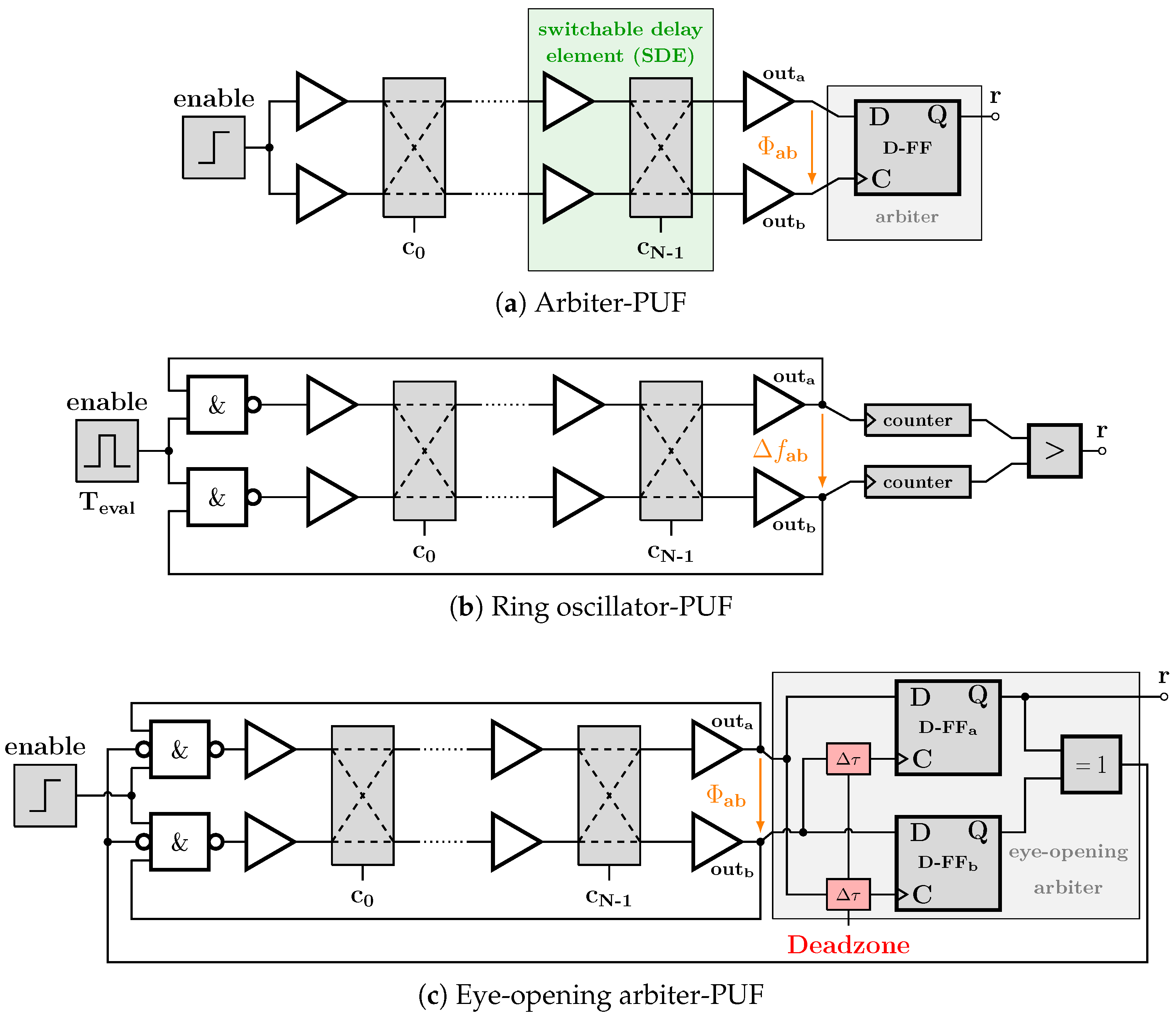
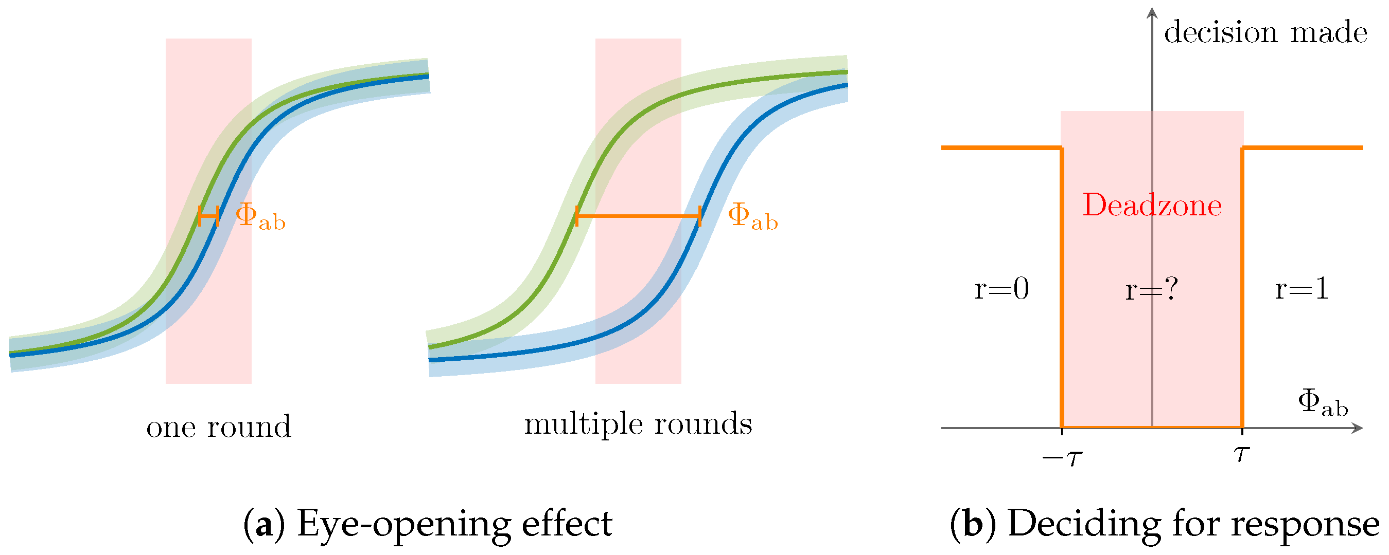
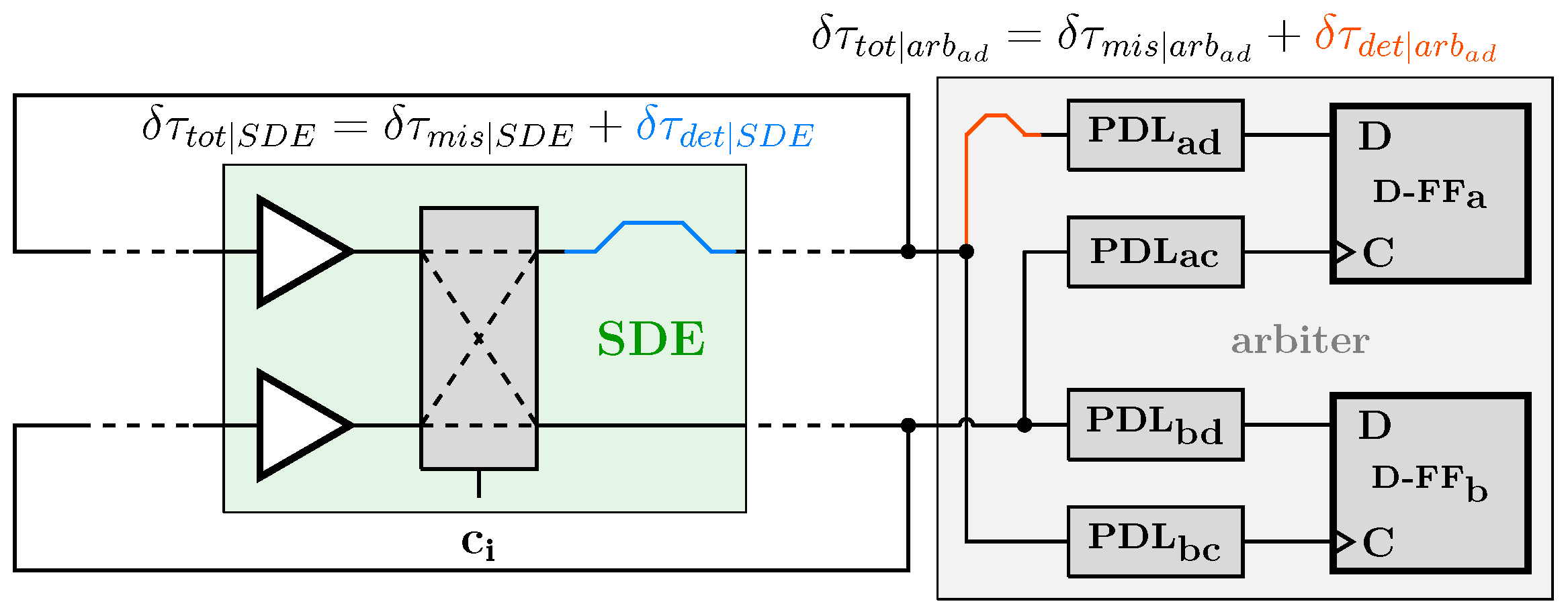
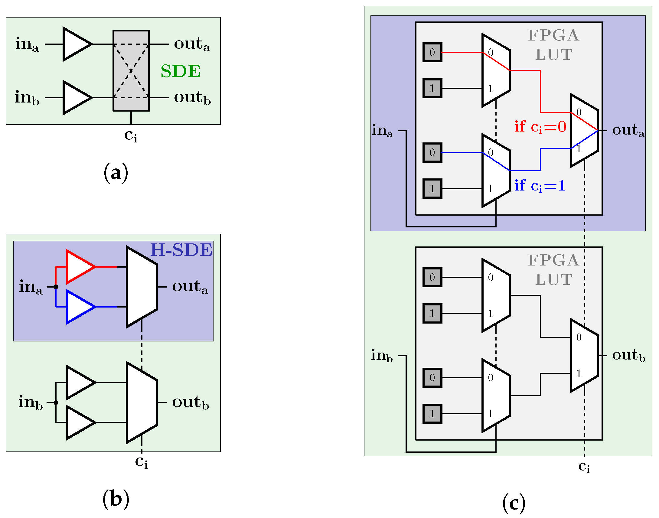
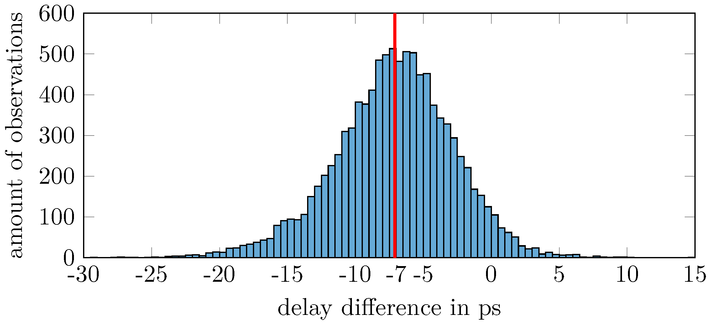
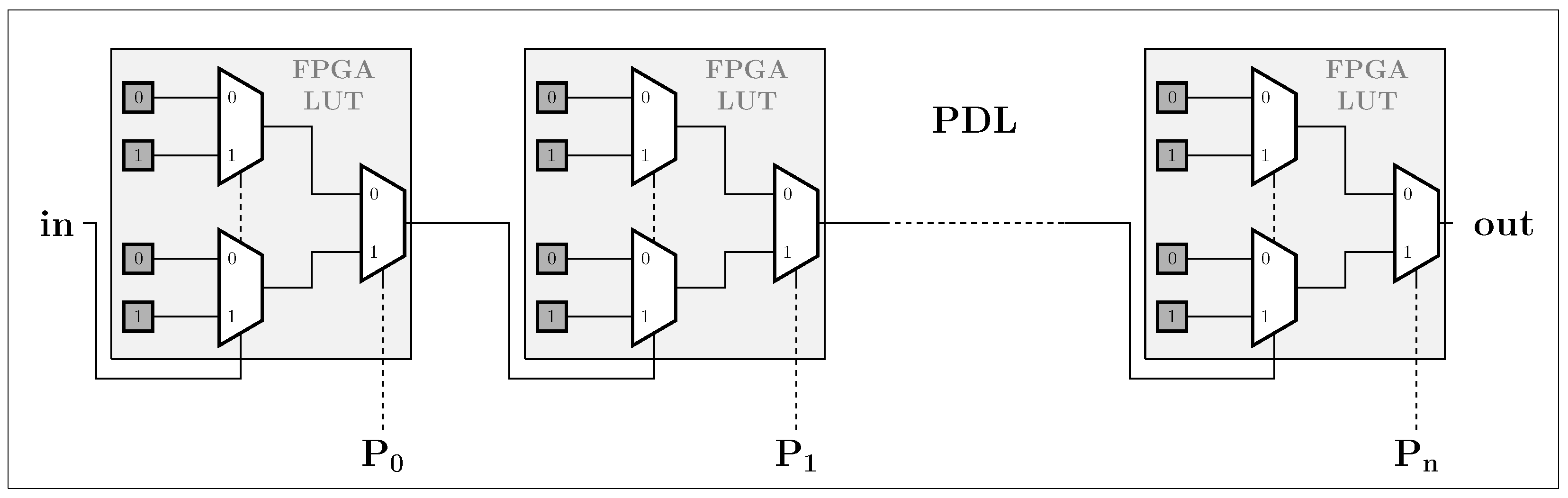
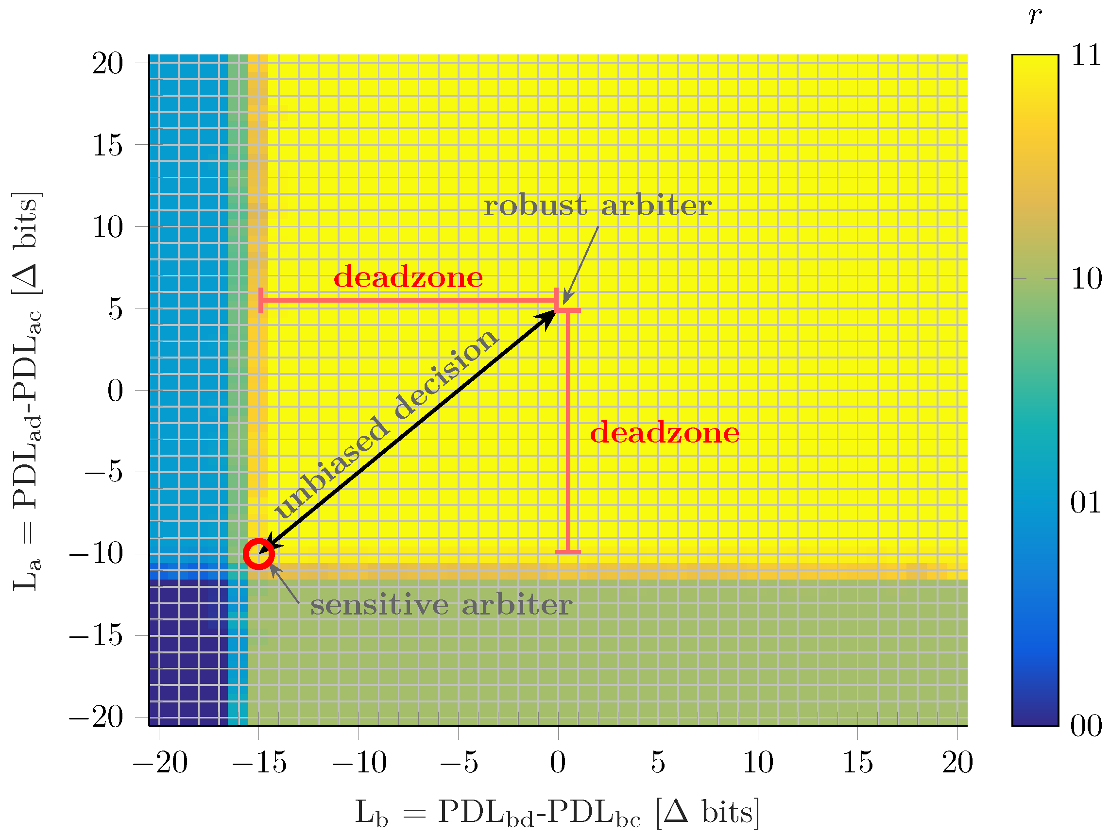
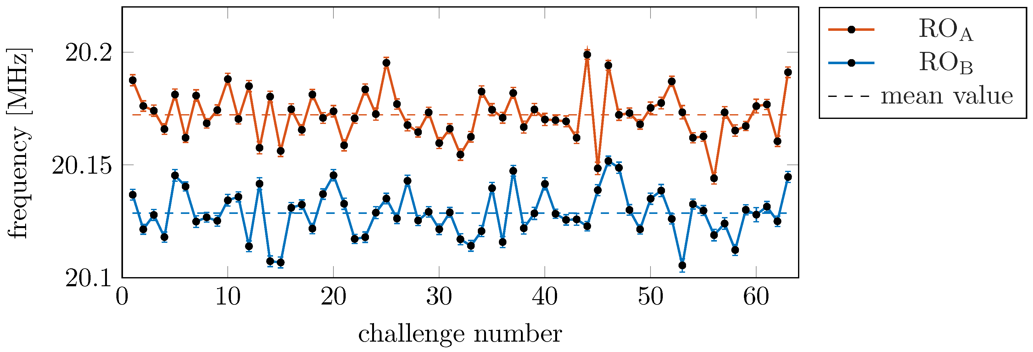
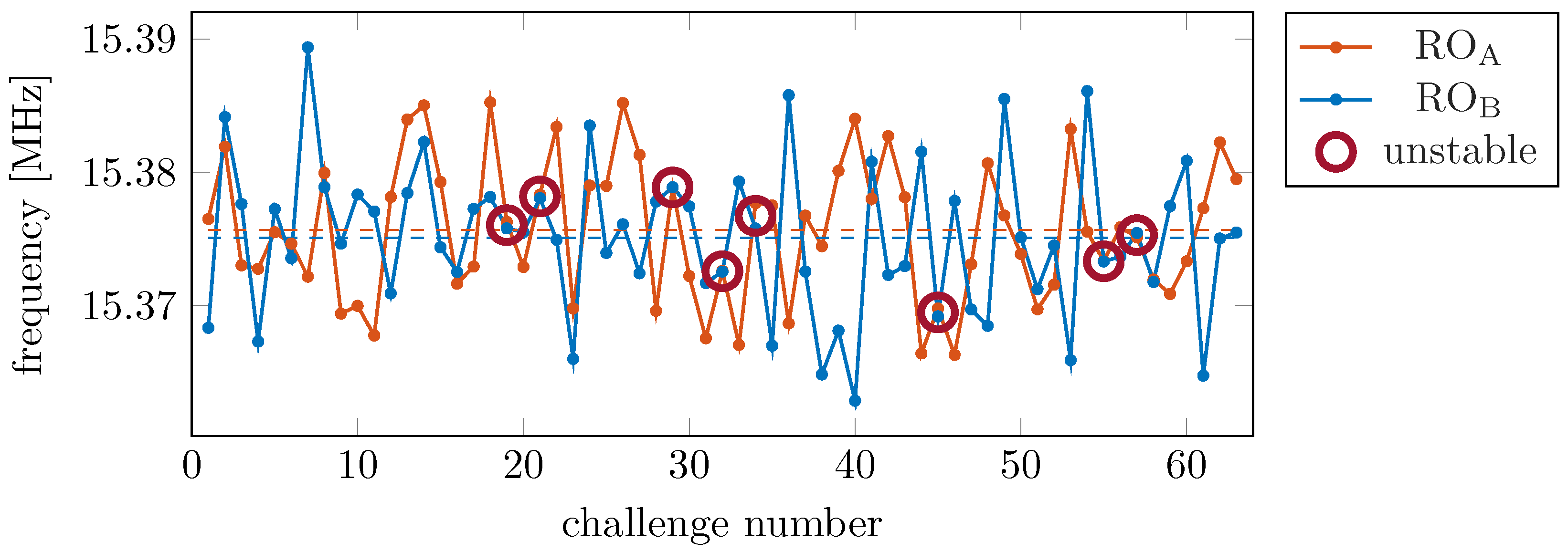
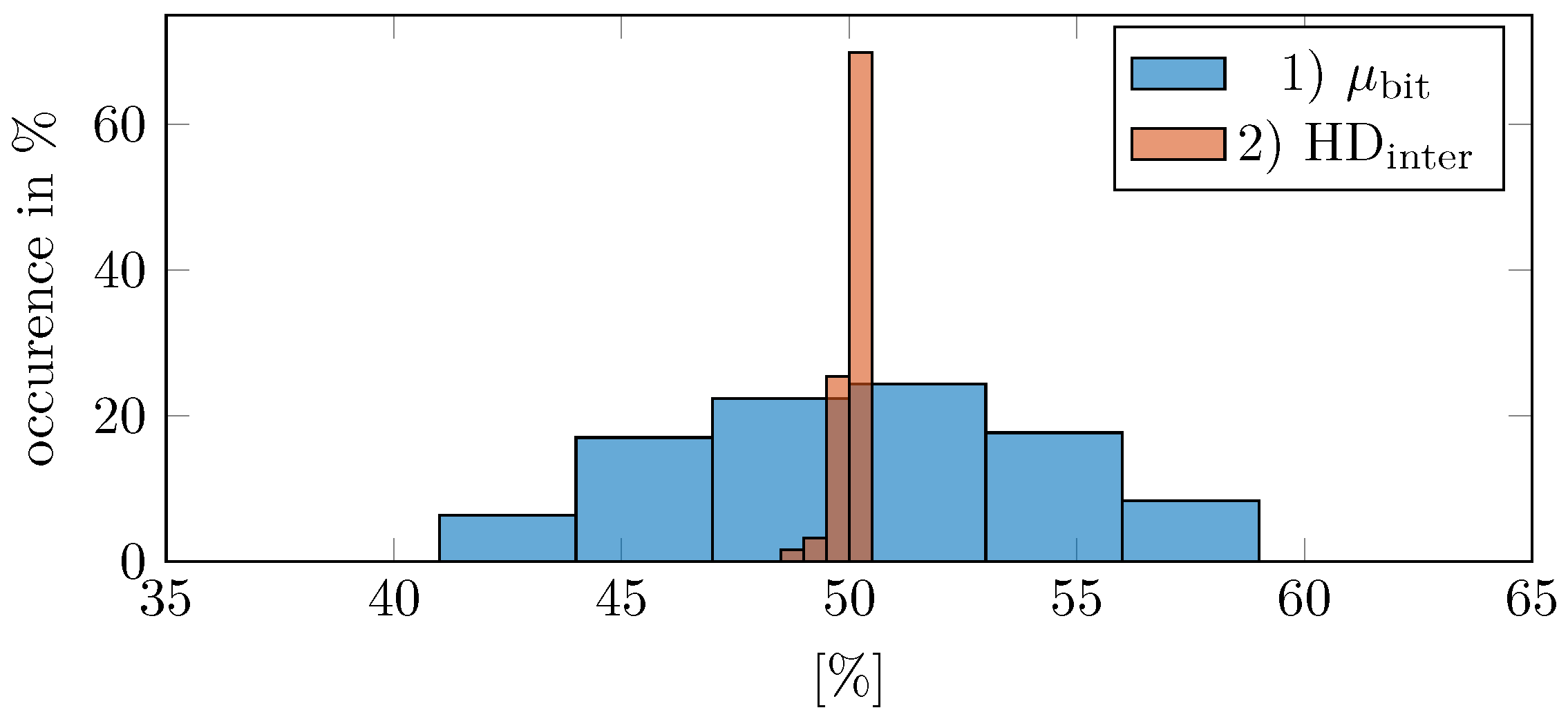

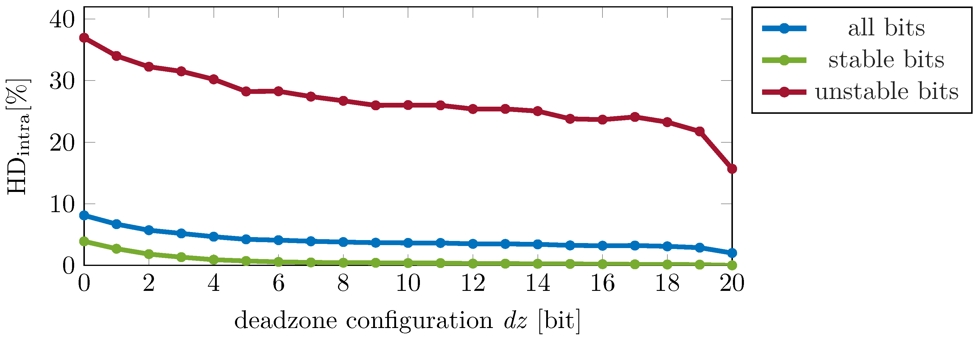
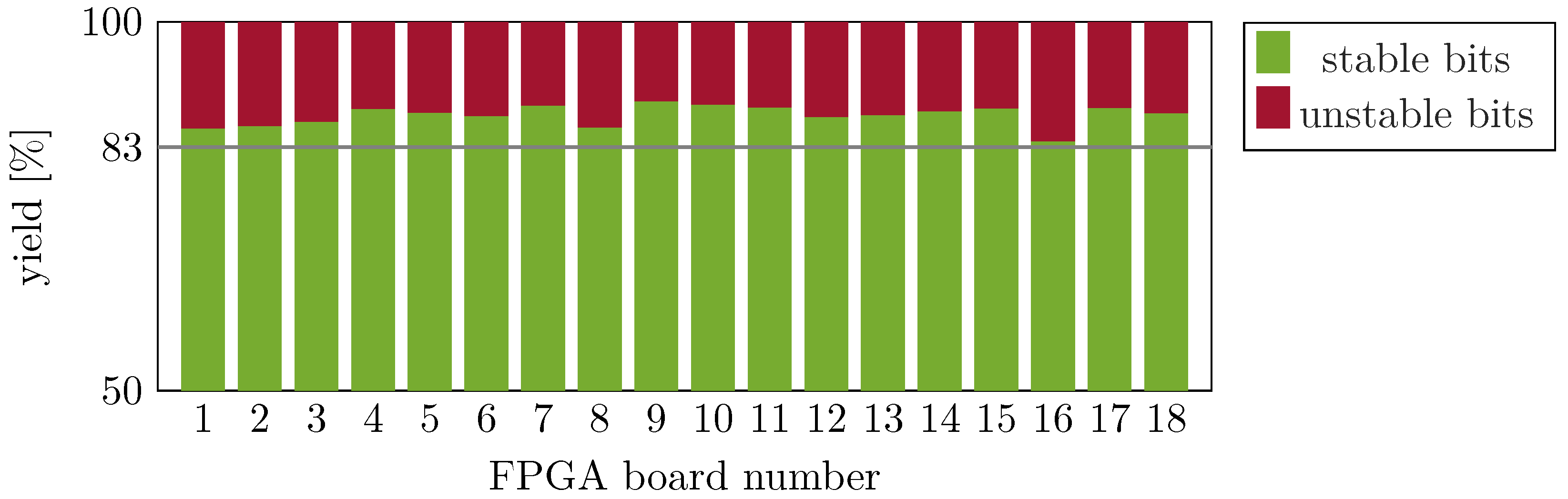
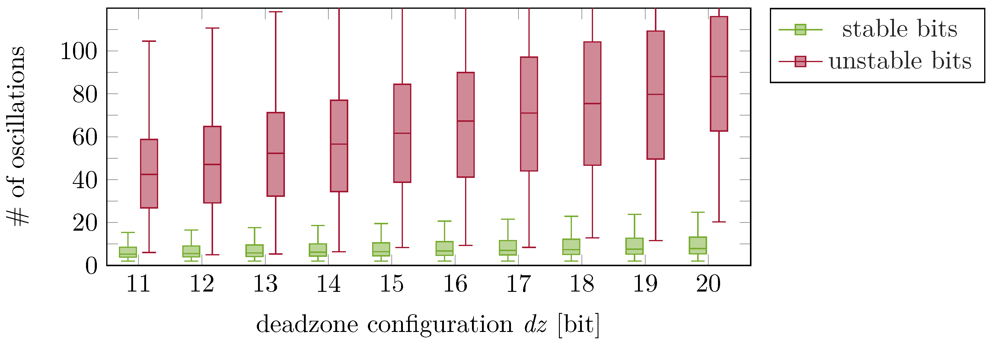
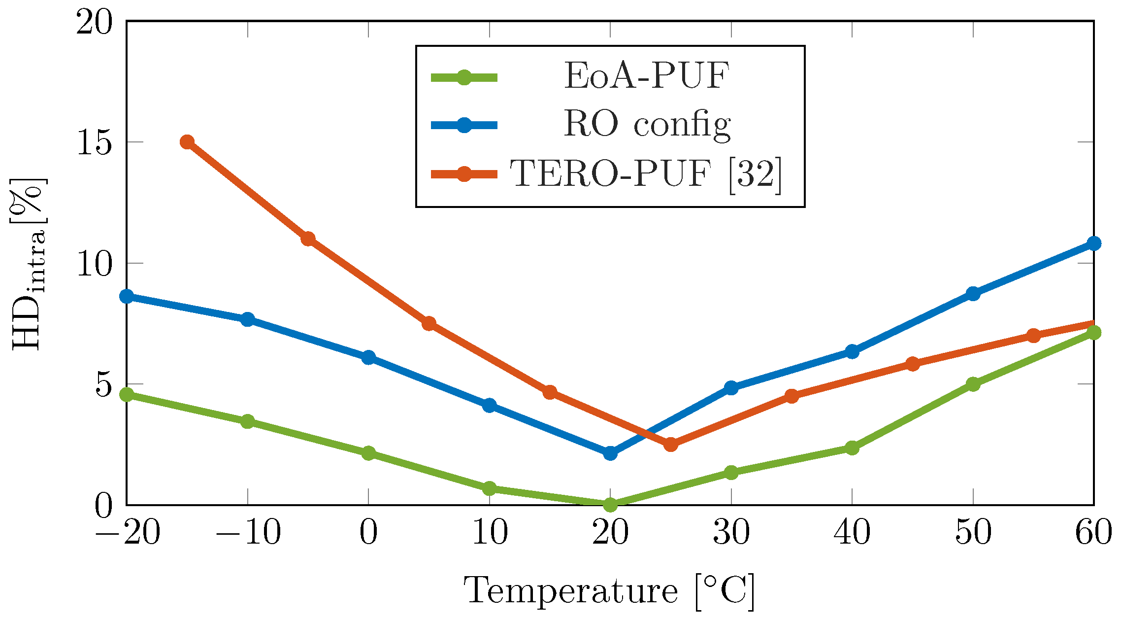
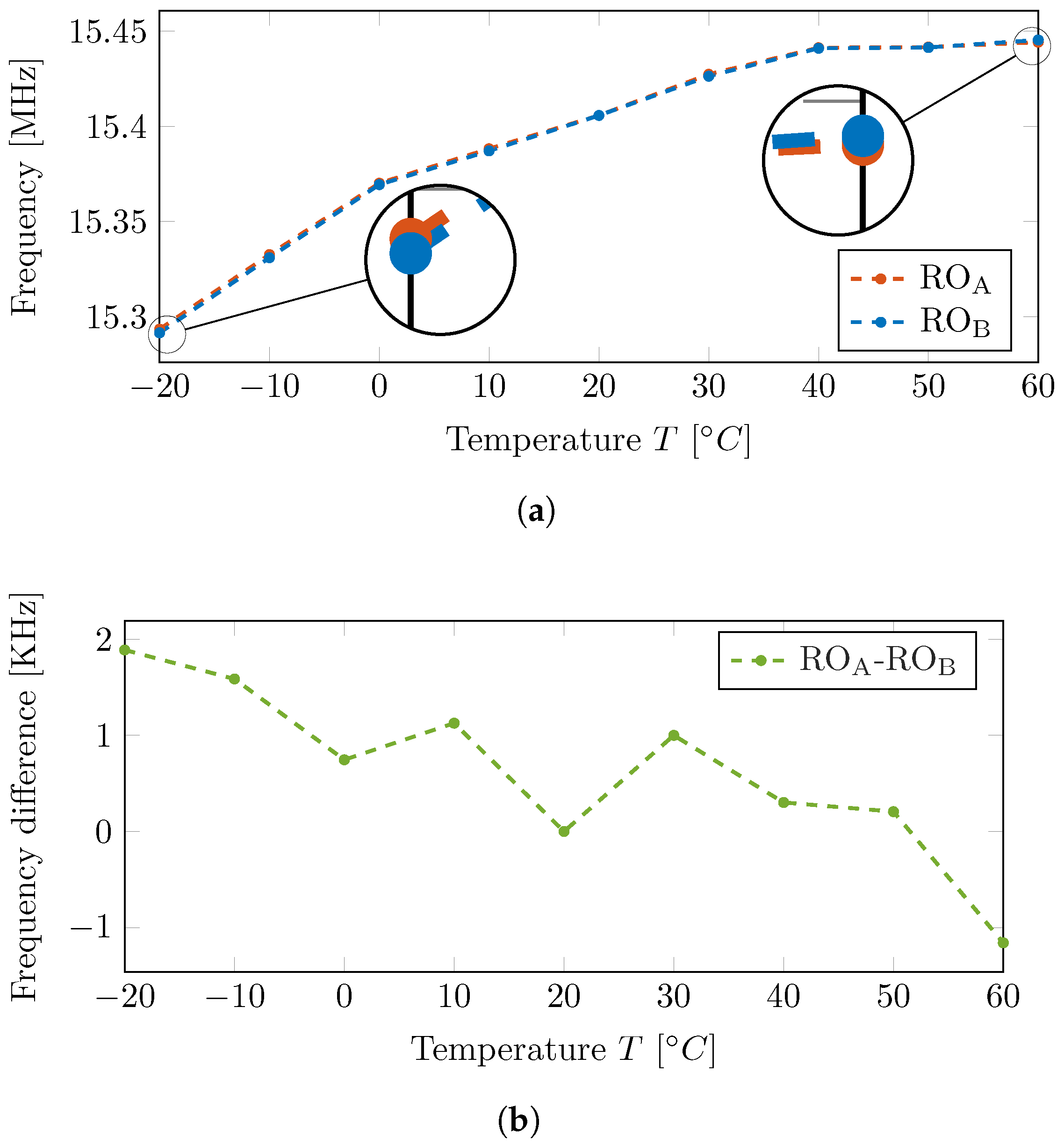
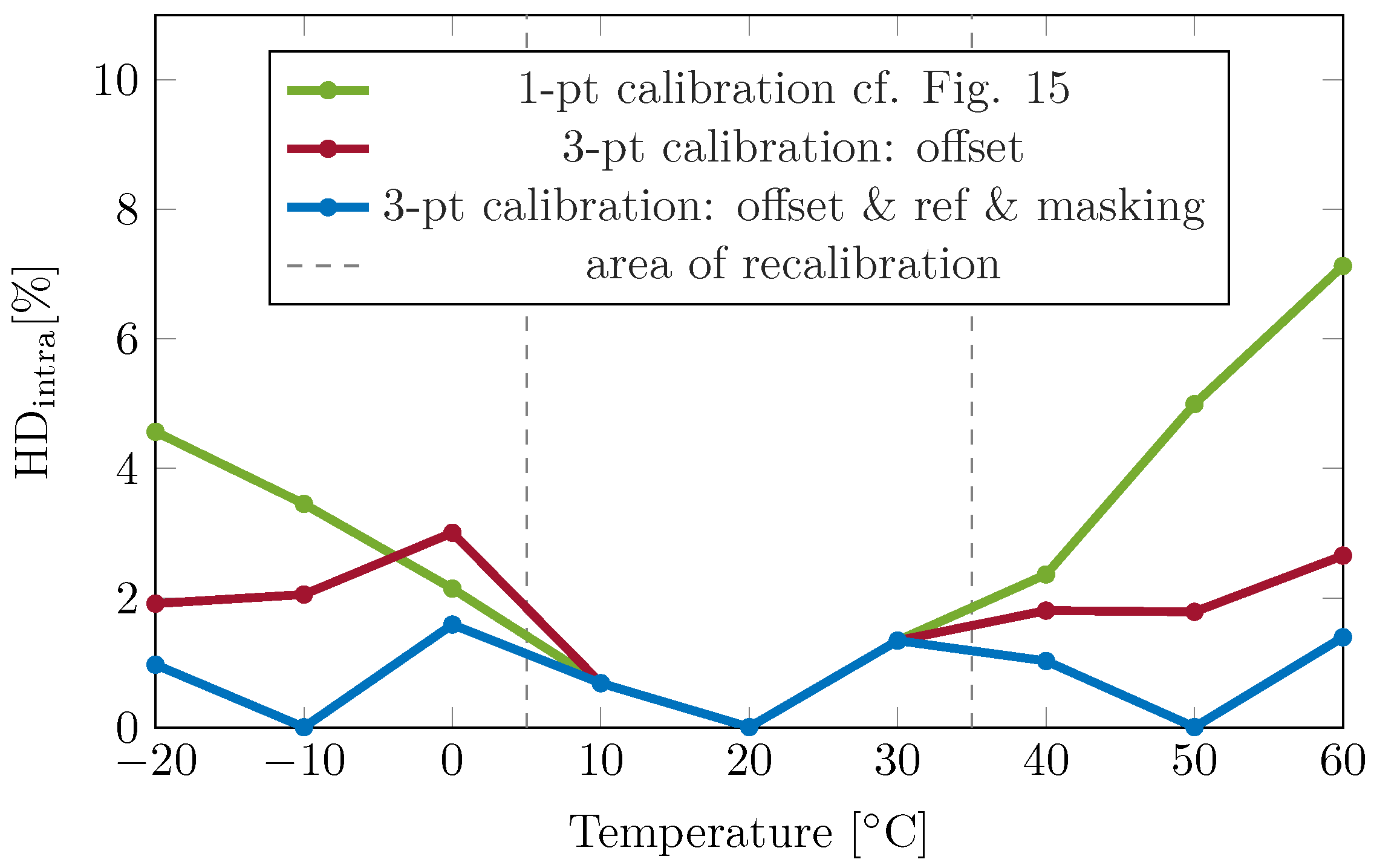
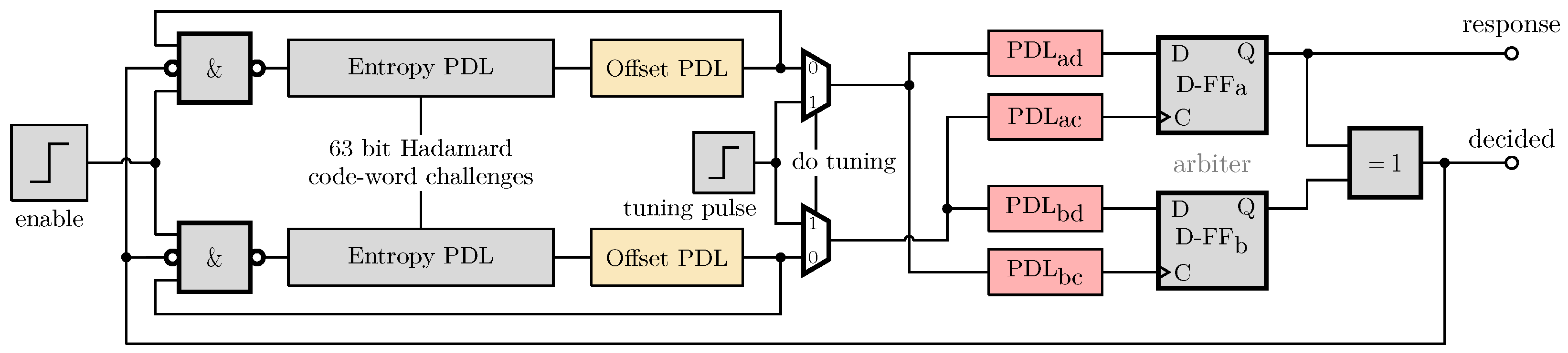
Disclaimer/Publisher’s Note: The statements, opinions and data contained in all publications are solely those of the individual author(s) and contributor(s) and not of MDPI and/or the editor(s). MDPI and/or the editor(s) disclaim responsibility for any injury to people or property resulting from any ideas, methods, instructions or products referred to in the content. |
© 2025 by the authors. Licensee MDPI, Basel, Switzerland. This article is an open access article distributed under the terms and conditions of the Creative Commons Attribution (CC BY) license (https://creativecommons.org/licenses/by/4.0/).