1. Introduction
In recent years, the security of sensitive data has become increasingly important, especially for embedded devices or Internet of Things (IoT) applications. It is crucial to ensure privacy and integrity while meeting hardware constraints. For instance, smartphones process a growing amount of sensitive data, and it is the responsibility of circuit designers to guarantee data integrity and prevent leakage. As a result, it has been widely accepted that hardware is an essential component of any critical electronic system and must be secure.
Data security can, to some extent, be improved by using cryptographic primitives, but physical limitations in power and space need to be considered as well [
1]. Striking a balance between hardware constraints and security is crucial. However, it may lead to design flaws that an attacker can take advantage of. Therefore, implementation must be carefully planned, especially if the attacker has physical access to the device. An attacker can study the device and use various physical attacks to achieve their objectives.
Several attack vectors have been identified that specifically target hardware implementations at various stages of a circuit’s life cycle and aim to compromise different assets [
2]. Therefore, various countermeasures have been proposed against specific attack vectors, such as side-channel analysis, fault-injection attacks, hardware manipulation, or counterfeiting. However, it has been observed that these countermeasures are not readily composable [
3]. A countermeasure that is effective against one type of attack may actually increase the vulnerability of the circuit to other attacks. For instance, in [
4], adding error-detecting circuitry to counteract fault attacks increased information leakage and, as a result, simplified side-channel analysis. This can be seen as a “security paradox”, where attempts to strengthen security against certain attacks can actually weaken the overall security of the system [
5,
6]. The objective of this work is to enhance the secure composition of physical attack countermeasures by identifying any potential negative consequences of specific countermeasures in other attack scenarios.
Various attack mechanisms can compromise cryptographic circuits, making them vulnerable. To prevent such attacks, several countermeasures have been proposed. Physical attacks, including algebraic fault attacks (AFA) and side channel attacks (SCA), are among the most prevalent types. AFA combines mathematical analysis and traditional fault attacks to recover the secret cryptographic key of a cipher. This technique derives equations from the algebraic descriptions of the cipher, fault-affected values, and a fault model. A SAT solver then processes the equations and the fault model to recover the secret key or limit the key space. SCA, on the other hand, captures side channel information such as power consumption or electromagnetic radiation to gather sensitive information about the cryptographic primitives. This is possible because the operation of cryptographic circuits can cause variations in power consumption or electromagnetic radiation that can be detected and analyzed. By capturing this information, an attacker can infer sensitive information about the cryptographic primitives, which can compromise the security of the system. Therefore, it is essential to implement proper countermeasures to prevent these attacks and ensure the security of cryptographic systems.
On the other hand, profit-driven globalization of integrated circuit design has resulted in many hardware-based attacks due to the outsourcing of fabrication to untrustworthy off-shore foundries. As a result, new techniques are necessary to safeguard Integrated Circuits (ICs) against various attacks. One such technique is logic locking, which involves modifying the circuit and adding new locking key inputs. These locking keys must be set to the correct values for the circuit to function correctly. Unfortunately, since its inception, several attacks have successfully broken logic locking, i.e., unauthorized users can determine the locking key [
7,
8]. The most relevant among these is the SAT attack, which helps categorize logic locking approaches into “pre-SAT” and “post-SAT” methods. The latter have been specifically designed to withstand the SAT attack. In order to counter these attacks, many countermeasures have also been proposed [
9,
10,
11,
12].
In this article, we show that the logic locking schemes proposed for security against supply chain threats are a weak link in protecting cryptographic hardware. The cryptographic primitives are resistant against (classical) cryptanalysis mainly due to their algebraic properties, and we show that when an adversary can apply incorrect locking keys, logic locking can destroy this resistance. We demonstrate that differential fault analysis (DFA) on incorrectly unlocked cryptographic circuits is simpler than on regular circuits without logic locking. We call the resulting attack locking-enabled DFA or LEDFA. Moreover, the circuit can even become vulnerable to classical differential cryptanalysis with no physical faults injected for some locking keys. We refer to this attack as LEDA. Note that neither LEDFA nor LEDA aims to attack the logic locking scheme itself (in fact, we assume an adversary with legitimate access to the circuit and correct logic-locking key). The target of the attack is the cryptographic key used by the primitive, and the locking circuitry is used as a vehicle to facilitate this attack.
Our article has a two-fold objective. Firstly, we intend to provide a comprehensive exploration of the LEDA and LEDFA algorithms, with particular emphasis on potential vulnerabilities resulting from logic locking. We will look into the intricacies of both algorithms and highlight potential weaknesses that an attacker could exploit. We will also analyze successful attacks to demonstrate why our attacks are successful. In addition to [
13], we have two new contributions. First, we propose a countermeasure against LED(F)A based on our findings and show empirical results to demonstrate its effectiveness. Secondly, we aim to also investigate the impact of logic locking on the side channel vulnerabilities of an AES module. We will conduct empirical assessments of power consumption traces to gain insights into the interaction between logic locking and the overall security profile of cryptographic circuits. Our study aims to provide valuable insights into how logic locking can affect the security of cryptographic circuits and highlight potential areas of concern for designers and developers. Overall, our article contributes to the ongoing debate on the security of cryptographic circuits and provides insight into improving their robustness against attacks.
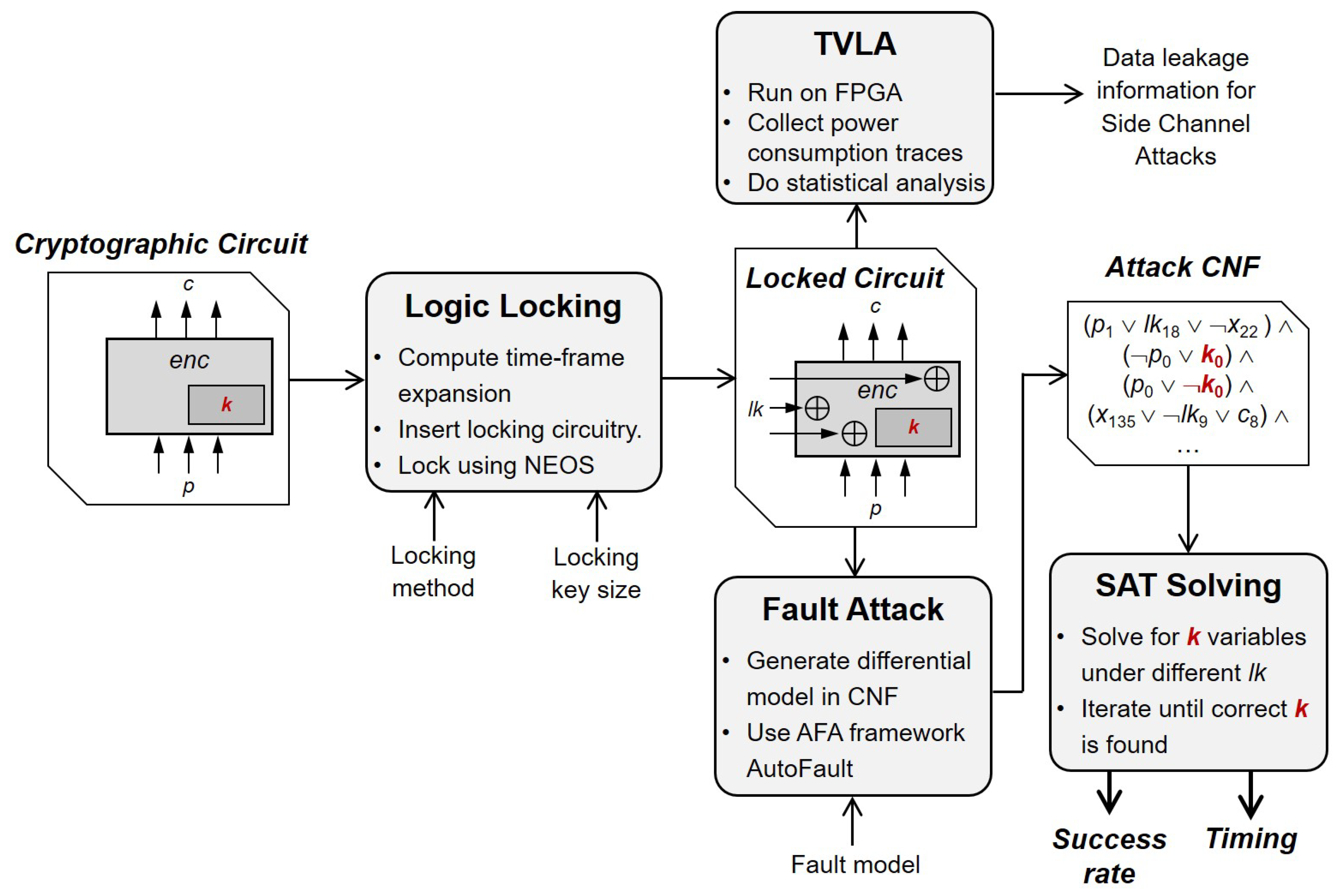
In order to demonstrate and study both LEDFA and LEDA, we developed a methodology which is summarized in
Figure 1. Firstly, we generated implementations of cryptographic circuits logic locked using a representative selection of schemes from the three prominent logic locking families: pre-SAT, modification-based post-SAT, and restoration-based post-SAT logic locking schemes. To achieve this, we extended the existing circuit with the locking logic and additional inputs for the locking key
, in addition to the regular inputs of the plaintext
p and the cryptographic key
k. Next, we ran DFA for the resulting locked circuit with the new
inputs fixed to either the correct or random incorrect values. To accomplish this, we used an existing algebraic fault attack framework that was extended to support locking key inputs. The AFA framework generates a fault attack for a user-specified number of fault injections for a given fault model. Specifically, it constructs a Boolean formula in its conjunctive normal form (CNF) that can be solved for the cryptographic key by plugging in the fault-affected circuit responses.
Our results show empirically that utilizing LEDFA with randomly selected incorrect locking keys is a more effective method than using DFA on a circuit that has no locking circuitry or has been correctly unlocked. Furthermore, LEDA, which does not require fault injections, has a success rate of 27% to 87% for lightweight ciphers, presenting a severe vulnerability since attackers can repeat the process using different incorrect locking keys until a successful attack. We conducted an extensive investigation into LED(F)A’s success factors, including the impact of non-trivial locking circuitry in post-SAT schemes and the optimal choice of the locking key. As part of this investigation, we have demonstrated cases where LEDA can successfully attack full-scale AES. Overall, we show that logic locking is a problematic technique for cryptographic hardware and goes against the principle of secure composition of countermeasures.
The remainder of the article is structured as follows.
Section 2 provides essential background information on fault injection attacks, side channel analysis, and different logic locking schemes. In
Section 3, we give a detailed motivational example.
Section 4 summarises the individual attack steps and explains the chosen threat model.
Section 5 reports on the experimental results. In
Section 6, success factors are analyzed, including the choice of a specific locking key and the propagation of cryptographic key bits through locking subcircuits.
Section 7 discusses a proposed countermeasure against LEDA. Finally,
Section 8 concludes the article.
2. Background
Cryptographic primitives, the foundational building blocks ensuring secure data communication, have historically been the target of various sophisticated attacks. One such prevalent modality is the fault injection attack. Within this category, differential fault attacks have been particularly noteworthy due to their mechanism of leveraging fault injections to instigate faulty cipher executions. Intriguingly, these faulty executions only marginally deviate from fault-free operations. This variation facilitates differential cryptanalysis across a truncated number of cipher rounds, amplifying the efficacy of these attacks. The potency of differential fault attacks is underscored by their ability to fully derive keys for ciphers, including, but not limited to, AES-128 [
14,
15], LED [
16], and PRESENT [
17]. Often, a singular or minimal fault injection suffices for this derivation. The ensuing data created from such injections are commonly channelled into specialized [
14] or generic equation-solving paradigms [
18], with the latter often rooted in Boolean satisfiability solving.
Parallel to these, the hardware domain grapples with an array of attack vectors predominantly centred on supply chain security. These threats span malicious circuitry alterations during design or fabrication phases, commonly known as hardware Trojans [
19], to more overt violations like piracy, cloning, counterfeiting, and overbuilding. The latter subset pertains to scenarios wherein circuits or their intellectual properties are unlawfully procured or originate from unauthorized entities [
20]. These challenges are ubiquitously pertinent but assume higher significance in the context of cryptographic circuits.
Several countermeasures have been proposed to counter such threats. These include camouflaging—obscuring identifiable hardware architectures to thwart recognition [
21]; logic locking—enabling circuit operability exclusively for authorized users possessing the requisite locking key [
22]; watermarking—infusing the circuit with an indelible authorial signature [
23]; fingerprinting—an augmented form of watermarking, it entails the inclusion of the purchaser’s identity [
24]; metering—a mechanism devised for the meticulous tracking of individual circuits [
25].
2.1. Logic Locking
Introduced in 2008 as part of the EPIC (“Ending Piracy of Integrated Circuits”) framework [
26], random-logic locking (RLL) adds key gates connected to new locking key inputs at random locations within a given circuit. However, in 2012 [
27], it was observed that an attacker with access to a functional (unlocked) circuit and a reverse-engineered netlist could make individual locking key bits observable at the circuit’s outputs. To counter against this threat, strong logic locking (SLL), fault-analysis-based logic locking (FLL) [
28], and look-up-table-based locking [
29] were proposed. However, these techniques were compromised by the SAT attack [
7], which used Boolean satisfiability (SAT) solving to compute “distinguishing input patterns” (DIPs) and thus reduce the key search space iteratively. The introduction of the SAT attack has led to the development of several new locking techniques such as SARLock [
9], Anti-SAT [
10], CASLock [
30], TTLock [
11], SFLL [
12], and cyclic Locking [
31].
In the recent literature, there exists a differentiation between pre-SAT and post-SAT logic locking techniques [
32]. The former employs key gates inserted into the netlist, varying only in their placement. The latter, on the other hand, utilizes point functions, which are Boolean functions that produce a value of 1 for only one point in the input space. This approach limits the extent of locking-triggered perturbation to the original circuit’s functionality, thereby reducing the valuable information for an SAT attack. Another type of post-SAT scheme is the cyclic logic locking scheme, which introduces loops into the combinational circuitry, potentially oscillating under incorrect locking keys. However, these circuits violate standard design rules, and we consider them impractical for cryptographic applications. This study assesses a representative selection of both pre- and post-SAT techniques, including two varieties of RLL as the most basic pre-SAT schemes and two post-SAT schemes, namely Anti-SAT and SFLL. All of the schemes utilized are discussed in detail below.
2.1.1. Random-Logic Locking
As mentioned before, RLL randomly inserts locking key gates in a netlist. There are two different schemes considered for this work: random XOR/XNOR insertions and random AND/OR insertions. We refer to them as “RLL-⊕” and “RLL-∧”, respectively, in the rest of the article. In RLL-⊕, we select n wires in the circuit, where n is the size of the locking key, and then introduce n new XOR/XNOR gates. We disconnect each wire’s driver from its sink and insert either an XOR or an XNOR gate. Whether we choose an XOR or an XNOR gate depends on the matched locking key bit. Similarly, in the case of RLL-∧, we randomly insert either an AND or an OR gate.
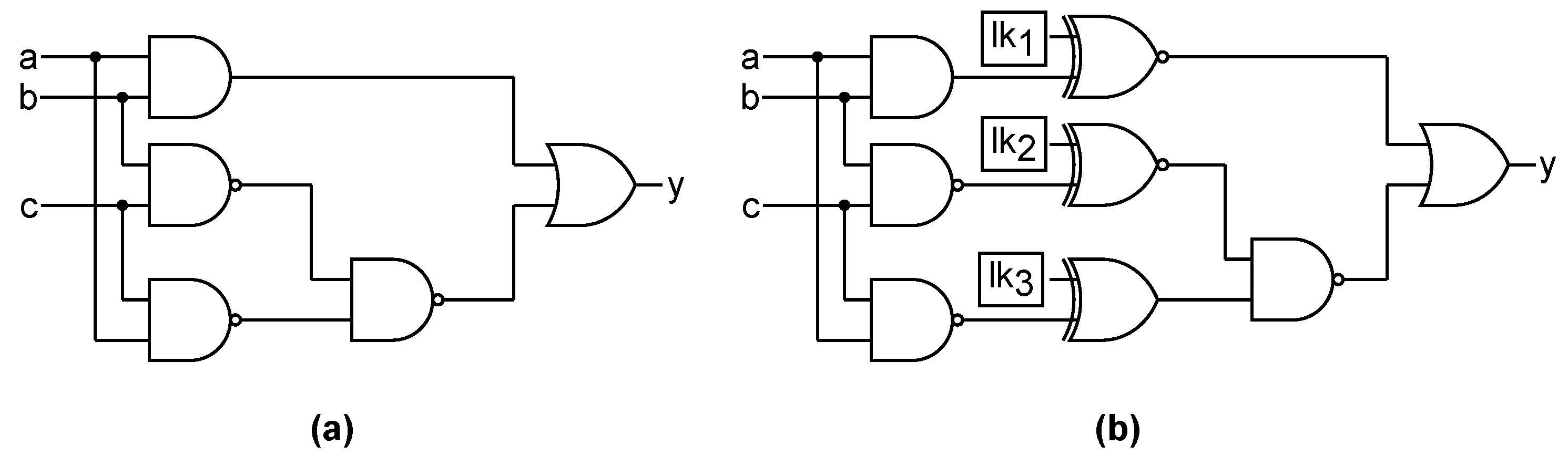
Let us consider
Figure 2a representing an original circuit, which consists of three inputs and an output. It comprises five gates. On the other hand,
Figure 2b shows the same circuit locked with
RLL-⊕ using a 3-bit locking key. This variant has three additional XOR and XNOR key gates. At least one of the inputs of each key gate is driven by a wire from the original design, while the other input is driven by a locking key bit. The new locked circuit will only generate the correct output when activated using the correct locking key. For instance, consider
Figure 2b again: if the locking key value of 110 is loaded into memory, the correct output for all input patterns (e.g.,
for input 000) is produced because all key gates will function as buffers. However, if an incorrect key value is used, certain key gates will function as inverters, resulting in errors in the circuit’s output. For example, when the locking key 010 and the input 000 are applied, the key gate
will behave as an inverter, leading to an incorrect output
.
2.1.2. Point Function-Based Logic Locking
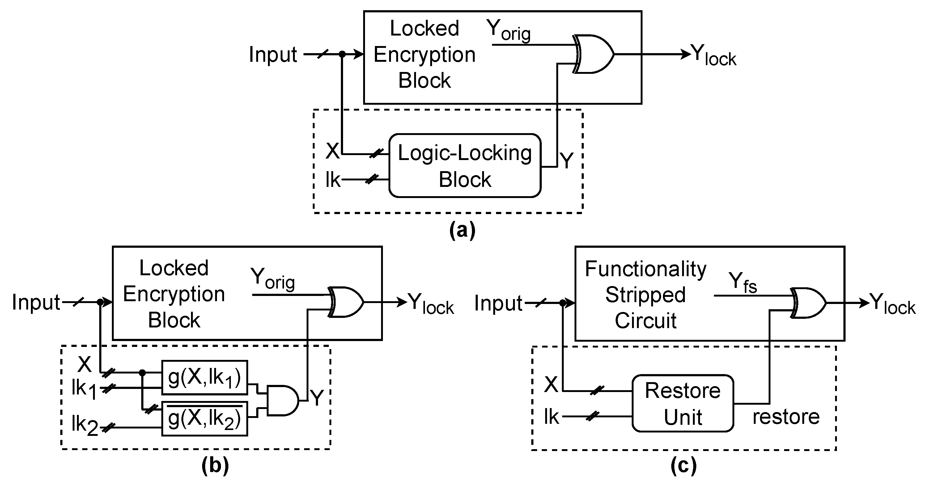
Let us take a closer look at a generic point function-based logic locking scheme, shown in
Figure 3a. These schemes utilize a
root and an
tree input set to embed the logic-locking block into a given circuit. The logic-locking block has as inputs the locking key
and the tree input set, or
X, which consists of a set of signals, either the primary inputs or intermediate wires. The size of this set is equal to the size of the locking key. The logic-locking block creates a point function Y, which is then connected to the randomly selected root within the original circuit. Our study investigates two schemes: Anti-SAT and stripped functionality logic locking (SFLL).
Anti-SAT, the circuit block shown in
Figure 3b, is relatively lightweight and consists of two functions,
g and
, that are connected to the same inputs,
X, and locked with two
n-bit keys,
and
. This results in a locking key size of
and a tree input set size of
n. If the correct
is applied to unlock the circuit, the outputs of
g and
must be complementary. These outputs are then fed into an AND gate to produce a constant output of
, which does not affect the original circuit’s functionality. However, suppose an incorrect locking key is applied. In that case, the complementary nature of
g and
is violated, and
Y assumes the value 1 for some inputs, which leads to incorrect functionality of the original circuit.
The hardware implementation of
SFLL intentionally removes parts of the design functionality through either gate insertions or replacements. As a result, the original design and the hardware implementation are not the same. A
restore unit is added to recover the correct functionality, as shown in
Figure 3c, which cancels the built-in error when the correct logic-locking key is applied. However, if an incorrect locking key is applied, it introduces additional errors in the design. With SFLL, designers can specify a permissible Hamming distance from the correct locking key. As a result, the restore unit recovers the original circuit behavior only when the locking key supplied by the circuit’s user is within the specified Hamming distance from the correct one.
2.2. Fault Attacks
Cryptographic primitives can be weakened using fault-injection attacks, which cause physical disruptions during their operation. These attacks can be simple and can be achieved through bit manipulation or clock frequency manipulation. When a cryptographic operation produces a faulty result, it can be observed at the circuit’s outputs, and the differences between the faulty and the fault-free results can be used to derive the secret information, such as the secret cryptographic key or the plaintext. Fault attacks involve physical fault injections on the circuit and the mathematical analysis of the observed data. The physical fault injections can be carried out in several ways, from glitching and underpowering to overheating [
33], optical, and electromagnetic fault injections [
34,
35]. These attacks are invasive and active; for example, to shoot accurately at a specific location with a laser, it may be necessary to decapsulate the chip.
The mathematical analysis consists of manual derivation to either obtain the cryptographic key or reduce the keyspace to a size that allows a brute force search [
14,
16]. Statistical techniques like those discussed in [
36,
37] can also be employed. Algebraic fault attacks (AFA) use an algebraic formula to map an attack, as described in [
18,
38]. Improving the solving process can increase the scope of the suitable attacks. Algebraic cryptanalysis is computationally intensive but does not require specific external data. At the same time, fault attacks, on the other hand, are data-dependent and may demand many fault injections to recover the secret key. Combining the two attacks can benefit from both of their advantages. The main idea behind AFAs is to use the cipher description and some fault injection data to retrieve the sensitive information. In order to launch a successful attack, an appropriate fault model must first be selected. The cipher and the selected fault are then expressed in their proper algebraic form. Finally, a solver is used to solve the algebraic equations, and if necessary, the incorrect key candidates are eliminated.
2.3. Side Channel Attacks
Side channel attacks are a type of physical attack that aims to exploit vulnerabilities in cryptographic circuits to gain access to sensitive information. Unlike invasive attacks that involve tampering with the system, side-channel attacks monitor auxiliary outputs such as power consumption or electromagnetic emissions. These attacks target the correlation between the processed data and the secret cryptographic key.
Differential power analysis (DPA) is one of the most prominent types of side-channel attacks. DPA, introduced by [
39], targets the correlation between the electrical power consumption of a cryptographic device and the operations it performs that depend on the secret cryptographic key. Statistical methods are used to analyze the power consumption, allowing the attacker to extract sensitive information.
The primary attack point of DPA is the dependence of power consumption on the operation performed by the cryptographic device. Multiple power consumption traces are measured for the fixed secret cryptographic key, and varying plaintexts are used. The resulting data are stored, including the measured power and the applied plaintext. With sufficient available traces, the first step of cryptanalysis is to specify a selection function that divides the measured traces into two sets based on an assumption of the secret cryptographic key. The average at each point in time is calculated and then compared for both sets. However, a large number of power traces are needed due to the presence of various hardware noises.
DPA has a critical advantage over brute force attacks because it allows the attacker to guess the key one byte at a time, significantly reducing the effort required and making DPA a highly effective tool for attackers seeking unauthorized access to sensitive information.
2.3.1. Test Vector Leakage Assessment (TVLA)
To evaluate the resilience of a cryptographic circuit against side channel threats, the TVLA method, as proposed by [
40], stands as an efficient tool. TVLA aims to detect potential side channel vulnerabilities rather than explicitly extracting the secret cryptographic key. The procedure involves examining the circuit using a consistent and known set of inputs. Two distinct datasets are required to evaluate AES using TVLA to mitigate the risk of false-positive results. The initial dataset comprises power traces from
encryptions, all employing a consistent, predefined cryptographic key, k, but varied random plaintexts. In contrast, the second dataset employs the same cryptographic key, k, encrypting with a static input
n times.
The objective is to determine the possibility of distinguishing between traces of fixed plaintext and the random counterparts, and is achieved through independent statistical evaluations with separate datasets. The first
measurements from both datasets are compared for the initial test, while the subsequent test uses the latter
measurements. A t-score outside the range of
to
, specifically during the middle phase of the AES operation, indicates a failed test. In the context of the
threshold, [
41] states it offers “a confidence of >0.99999 to reject the null hypothesis”. This t-score corresponds to the t -statistic in Welch’s
t-test, where a significant deviation from zero suggests a discernible difference between the two sets. Therefore, to meet the requirements of the TVLA, a small absolute value of the t-statistic is desired. Notably, a system is more vulnerable to a side channel attack if it fails the TVLA. However, passing the TVLA does not conclusively prove that the circuit can resist side-channel attacks. Even with a successful test outcome, it is essential to corroborate the findings through additional evaluation methodologies.
2.3.2. t-Test
After collecting the traces, Welch’s
t-test is conducted on the datasets—the
t-test tests whether two sets exhibit the same mean. Thus, a test failure would indicate that statistically significant differences in mean are present between the datasets. In the context of TVLA, the rejection of the null hypothesis—that the two datasets possess identical means—implies security vulnerabilities within the device under inspection [
42]. Contrarily, the acceptance of the null hypothesis suggests an absence of discernible security vulnerabilities. However, it is crucial to note that the absence of evidence does not guarantee the device’s intrinsic security.
For an implementation of TVLA, it is specified that two independent tests be executed on mutually exclusive datasets. The first test is done with the initial half of the dataset, while the second test evaluates the latter half. The t-statistic is meticulously calculated for both tests. Let us denote
and
as the means of the random and fixed datasets at any specified point within the set of sample points. Similarly, let
and
represent the sample standard deviations of the random and fixed datasets, while
is the number of traces used to test the random dataset and
is for the fixed dataset. The t-statistic is thus expressed by:
After the t-statistic computation across all sample points, whether these values reside within the interval [−4.5, 4.5] is determined. Any deviation of the t-statistic from this specified interval implies the rejection of the null hypothesis, indicating potential security vulnerabilities. The choice of this interval, precisely [−4.5, 4.5], aligns with a confidence level of 99.999%, thereby minimizing the probability that observed disparities between datasets arise merely from stochastic variances [
40].
3. Motivational Example and Attack Assumptions
In this segment, our objective is to provide a clear explanation of the concept of locking-enabled attacks. To achieve this, we will present an example of LEDFA that is based on a basic but rather unrealistic scenario, which will help in understanding the idea in a simple way. Following that, we will introduce our actual adversary and threat model in the next section, providing a more practical perspective. We implemented a gate-level version of the PRESENT SBox with a Boolean function , and locked it with a 4-bit locking key using RLL-∧ to illustrate the concept. This changed the Boolean function of the SBox to and led to the addition of four new inputs, . Only one among the 16 potential locking keys is correct; in that instance, for all , . The adversary can apply any other , which will change the SBox’s function, or the correct to use it normally.
Now, we will show how logic locking can make the SBox and the cipher as a whole more susceptible to differential cryptanalysis. The
difference pairs (
) for the SBox will be computed for this purpose. These are pairs of inputs
that satisfy
and
[
43].
Table 1A displays the resulting
difference distribution table (DDT) for the standard SBox without any locking circuitry (or, equivalently, a locked circuit unlocked with the appropriate locking key). For instance, entry 2 in row 7 and column 2 shows that
is equal to the number of input pairs
with
. Aside from the simple case
, this is also the largest number in the DDT. Greater DDT entries suggest that the SBox is more vulnerable to differential cryptanalysis. Since there is no such thing as a mathematically impossible “ideal” SBox, all differential values would be 1, suggesting maximum resistance.
We unlocked the PRESENT SBox with all possible locking key combinations, and then we exhaustively computed the differential distribution table (DDT) for every resulting function,
. Because the resulting function
for
had the weakest DDT against differential cryptanalysis among all the resulting functions, we decided to use
for our motivational example. The corresponding DDT, shown in
Table 1D, is susceptible to differential cryptanalysis because it contains multiple entries with a value of 12. Furthermore, there exist several input differences for which the resulting “SBox” is not a bijective mapping, as evidenced by the fact that the output difference is 0.
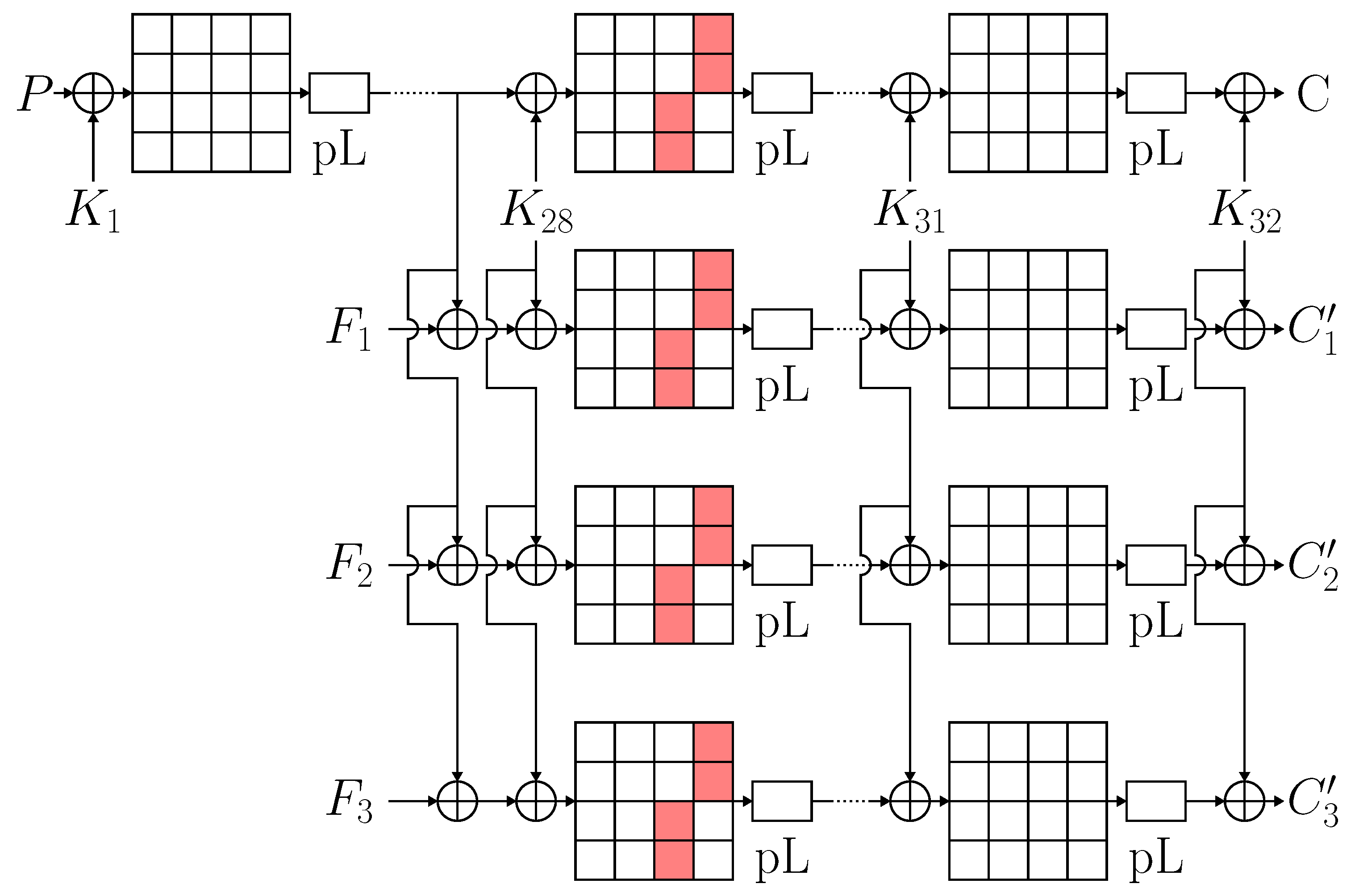
Next, we attempted DFA on an implementation of PRESENT where four out of 16 SBoxes in round 28 were replaced by the locked version
with
determined by the DDT analysis above. This is shown in
Figure 4 (using three faults according to the nibble fault model explained in detail further below). Four copies of the modified PRESENT (one fault-free and three fault-affected circuits) were used to build a differential model, which we then converted into conjunctive normal form and solved using the SAT solver CryptoMiniSAT.
The outcomes of this experiment, along with another using the same SBox and LED in place of PRESENT, are displayed in
Table 2. The percentage of attack attempts that yielded the correct cryptographic key is indicated by the “success rate”. Once the remaining attack attempts had been solved for 18,000 s, they timed out. It is observed that the complexity of attacks was significantly lower for implementations with incorrectly unlocked SBoxes. With LEDFA, attacks that were previously unfeasible for DFA become possible, and the run time is drastically decreased. This is not surprising, as the DDT analysis shows that the cryptographic strength of the SBoxes has been significantly diminished.
The example in this section shows how LEDFA can be used, but more discussion is needed to fully understand its viability. It is a realistic assumption that adversaries can gain access to the circuit by using both the correct and the incorrect locking keys. The right locking key () must be applied by legitimate users in order to confirm their authorization. As a result, an externally accessible interface is required to provide locking keys. Given that anyone purchasing the circuit can easily obtain the correct locking key, it is also conceivable that adversaries are aware of it. However, the cryptographic key k is not accessible from the outside as it is kept in a protected memory inside the circuit. Recovering this cryptographic key k is the primary goal of LEDFA. Importantly, the adversary does not need to exert any further effort in order to apply an incorrect locking key. Simply said, they can apply various logical values to the circuit’s standard inputs.
In the example, it is assumed that the four locking key gates of RLL-∧ have affected the four SBoxes of the circuit in a particular way. If the locking scheme applied to the entire PRESENT circuit includes four key gates in each of these four SBoxes at precisely the same positions as determined by the DDT analysis, then such an effect of logic locking could occur. This assumption, however, is improbable because the key gates are inserted during the manufacturing process and may be positioned at random or in response to the structural characteristics of the circuit. They can be placed in any of the other blocks or within the SBoxes. It is crucial to remember that adversaries are limited to using the provided locked circuit and cannot move or add new key gates. We therefore adhere to the white-box assumption, which states that although the adversary is unaware of the values of the cryptographic secret key k, they are aware of the gate-level implementation of the cryptographic circuit, including the circuitry related to locking. It is also assumed that there are no specific countermeasures included to thwart or impede fault attacks. Future research, though, can address this in more detail.
The next section will include a more thorough description of the LEDFA attack steps along with a more formal summary of the threat model.
4. Attack Overview and Threat Model
A cryptographic function is assumed to have a logic-locked implementation . Three inputs are provided to : plaintext p, cryptographic key k, and locking key . The function computes a ciphertext . An adversary can choose a p to apply to the circuit’s inputs and then record the resulting ciphertext in accordance with common assumptions about differential fault attacks. The adversary’s goal is to recover the value of the cryptographic key k, which is safely stored within the circuit. Adversaries also have the ability to apply various values to as an input. For any given specification (), there is only one correct locking key fitting the description. Incorrect behavior will arise from applying an incorrect ; however, tracking or detection is absent, i.e., the adversary can use the circuit with the wrong locking keys, and it will not have any negative effects, like output randomization or blinding.
A physical disturbance represented by a fault
f is injected into the circuit while it is being used for the differential fault analysis (DFA). Generally speaking, an attack can include several fault injections, i.e., repeatedly utilizing the cryptographic circuit for encryption with faults
The behavior of the circuit under
fault is given by
. The adversary might not be completely aware of or in control of the fault injection’s effect in most situations. Thus, it is unknown what intermediate values are impacted. With the same inputs,
p and
, the adversary records the ciphertext
C generated by the fault-free circuit and the faulty ciphertexts
generated by the same circuit, upon injection of the corresponding faults,
The cryptographic key is then recovered by solving the equation
after
k. To build the equation, we assume that the adversary is aware of the gate-level implementation of the circuit, including the locking circuitry. Reverse engineering [
44] can be used to determine this information, even though it is not always available in practice; in DFA literature, it is typically assumed that the attacked function is known.
The presence of input
sets our proposed attack apart from other traditional fault attack techniques. As was shown in the previous section, the function can be changed to a cryptographically weaker version,
, if an incorrect locking key
is used. If the incorrect locking key is used to mount the fault attack, Equation (
2) may become easier to solve.
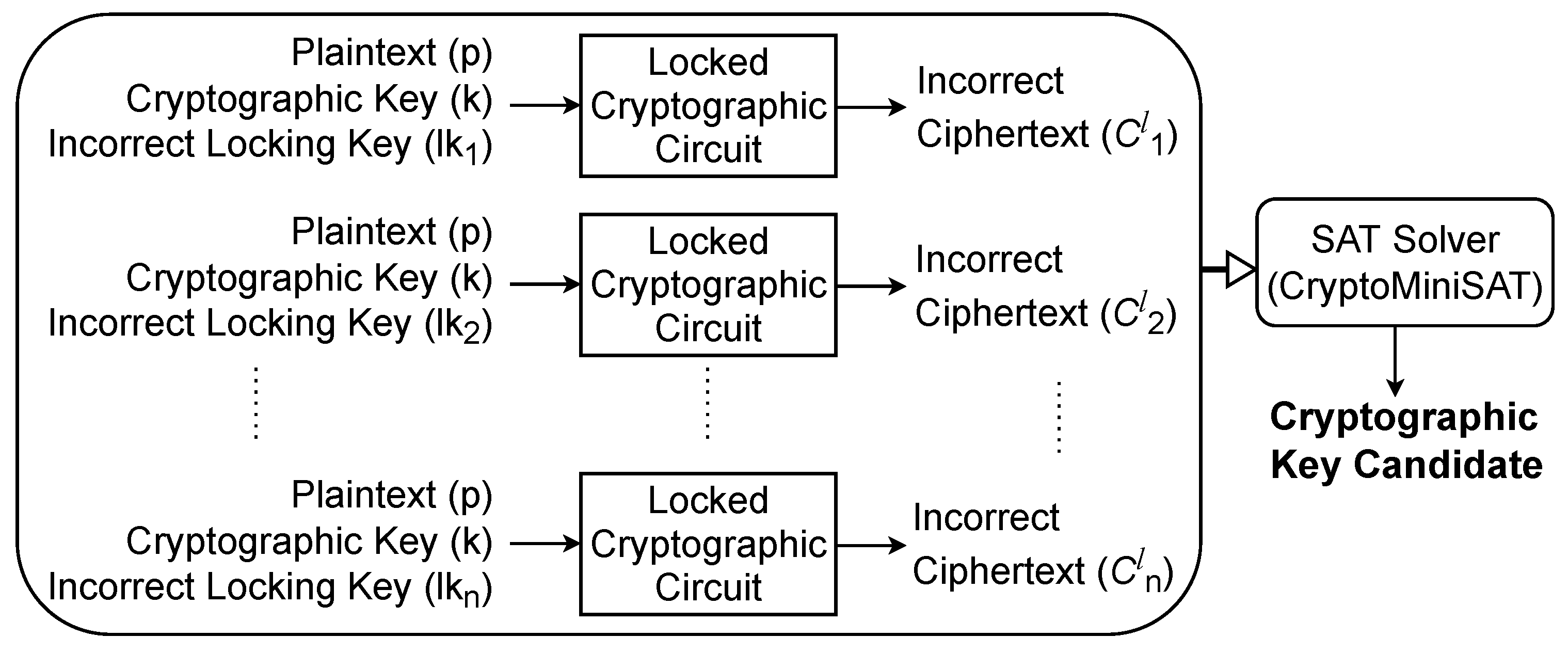
To perform LEDA, we use fault-free encryptions; we generate multiple ciphertexts with distinct locking keys:
Take note that
need to be pairwise different; the correct locking key can be one of them, but it is not required. Solving the equation
after the cryptographic key,
k becomes computationally tractable for at least some cases. In this case, using the wrong locking key has a function that is comparable to fault injections in DFA. There are, nevertheless, a few significant differences. Unlike many injection techniques, LEDA does not suffer from inadequate spatial or temporal resolution and does not require fault-injection equipment. Since there are no peculiar circuit conditions as a result of the physical disturbances, it is rather challenging to detect using the built-in sensors. On the downside, since the locking circuitry does not affect every location in the circuit, LEDA cannot cause arbitrary faults (from the adversary’s perspective). Nonetheless, we demonstrate that the areas impacted by the locking key are frequently adequate for recovering the secret cryptographic key. Furthermore, it should be noted that Equation (
3) may not be computationally tractable for arbitrarily large values of
; in fact, we found a less than 50% success rate in all cases that were examined. This is not a major drawback for an adversary who can simply keep trying other locking key combinations until one recovers
k.
Remember that in order to illustrate LEDA and LEDFA,
Figure 1 shows how the attack is set up in general; recall specifically that logic locking is applied to a cryptographic circuit is the first step. In an actual attack scenario, it is assumed that the locked circuit already exists. The remaining steps of the procedure show how to use the AFA framework, AutoFault, which is described in [
38], to launch an algebraic fault attack against the locked circuit. The ensuing subsections contain more specific information about each step.
4.1. Time-Frame Expansion
Two methods can be used for the hardware implementation of round-based ciphers: one is to use a sequential circuit where the logic for one or more rounds generates intermediate outputs that are stored in registers, or one is to use a combinational (unrolled) circuit that contains logic for each round. Propositional models, which are needed for the SAT solvers at the core of the AFA framework used in this work, can be obtained by applying the Tseitin transform [
45] to combinational circuits in order to convert them into a Boolean formula. Unrolling or time frame expansion must be used to create a functionally equivalent combinational circuit for a sequential circuit. In essence, this procedure is a one-cycle implementation of the circuit’s original description. It is important to remember that test pattern generation for sequential circuits or sequential equivalency checking commonly employs the time frame expansion technique.
4.2. Logic Locking
We used a publicly available synthesis program named Netlist Encryption and Obfuscation Suite (NEOS) [
46] to generate the locked circuits. Random-logic locking variants comprise seven of the available schemes. For this work, we consider two of them, XOR/XNOR and AND/OR insertions at random. Additionally, three logic locking schemes based on point functions are supported by the tool. As an example of these, we take Anti-SAT and SFLL. Furthermore, as noted in
Section 2.1, we believe that the four cyclic locking schemes that NEOS supports are not suitable for use in cryptographic implementations. Universal logic locking, the final supported scheme, maps the circuit to a structure resembling an FPGA, with the configuration bits acting as the locking key once they are set after manufacturing. The adversary could easily prevail in our threat model, where users have the ability to apply arbitrary locking keys, by setting up the FPGA to propagate the cryptographic key to all of its outputs.
NEOS creates a locked version of the given (in our case, cryptographic) circuit after receiving a gate-level netlist of the circuit. We had to re-synthesize our circuits before inserting them into NEOS since it can only process specific gates (
Figure 1). The user can specify the number of locking key bits in addition to the locking scheme to be used; in our experiments, we generated circuits locked with 32, 64, 80, and 128 bits.
In our experiments, logic locking is applied after the circuit is unrolled using time frame expansion. As a result, the matching locked cryptographic circuit is combinational, meaning that key gates can be positioned anywhere in the circuit and that it is completely unrolled and functional in a single clock cycle. On the other hand, in a sequential implementation, the key gates would be positioned inside the combinational core and would, therefore, appear in each frame. By applying the appropriate locking key bits to the key gates that are not required in a given clock cycle, an attacker can activate or deactivate specific key gates in each clock cycle, assuming that locking key inputs are regular circuit inputs. As a result, there would always be an equality between the sequential case and the combinational cases. This was done specifically in order to streamline the tool flow.
4.3. CNF Generation
Equations (
2) and (
3), which are represented by propositional (Boolean) formulae in conjunctive normal form (CNF), serve as the foundation for the LEDA and LEDFA attacks. A Boolean function that could be mapped to CNF is implemented by a combinational circuit with
n input and
m output made up of logic gates; however, this mapping is not very effective. For every logic gate in the circuit, the Tseitin transformation produces a
characteristic function. For consistent assignments to the inputs and outputs of the corresponding gate, the characteristic function is 1. For instance, the characteristic function of an AND gate with inputs
a,
b and output
c is
The conjunction of the characteristic functions of each gate in a circuit is the circuit’s characteristic function. It is satisfiability equivalent to the circuit’s Boolean function; however, it has additional variables for internal signal lines.
The characteristic function CNF can have unit clauses (
) or (
) added to it, respectively, to force a chosen signal line
to 1 or 0. A SAT solver for such a formula can report that the formula is unsatisfiable or yields a consistent assignment to the circuit’s inputs and other variables where
has the desired value for the given assignment. The output restrictions “
” in Equations (
2) and (
3) are implemented using this technique, where
is a constant vector made up of ciphertext bits that are physically observed on the outputs of the circuit under. The Boolean variables or literals corresponding to the output bits are found and added to the CNF as unit clauses, which are negated in the case that the observed bit was 0 and non-negated in the case that it was 1.
4.4. Attack Construction and SAT Solving
The formula for LEDA (Equation (
3)) or the fault-assisted LEDFA (Equation (
2)) is built using the AFA framework AutoFault [
38]. The (time-frame-expanded) circuit for LEDFA has
k copies in the attack formula, along with
k fault injections. To build CNF parts for terms such as
, more details regarding injected faults are required. Included in this is the fault model (e.g., stuck at fault, bit flip, delay-based glitch), the round in which the fault is injected, the position of the fault within the round, and the number of faults injected concurrently. We employ a popular
random byte fault model for DFA in this work. An arbitrary subset of bits within that byte can be flipped; the attacker is oblivious to which bits have been flipped. It is assumed that the injected fault affects one byte of the cipher state.
An SAT solver was given the attack formulae that were created with the AFA framework. We tested a number of SAT solvers, and since CryptoMiniSat [
47] produced the fastest solving times, we used it for all of our experiments. The attack formula typically does not have a unique solution because of the random byte or nibble faults used, and it may produce a key candidate that is not the correct cryptographic key. In order to confirm these cryptographic key candidates, an encryption with a known plaintext/ciphertext pair must be performed. A conflict clause is added to the CNF to remove the candidate from the solution space and rerun the attack if it turns out not to be the correct cryptographic key.
Equation (
3) describes the method used for the fault-free LEDA in the same way. Nevertheless, rather than modeling fault injections as seen in
Figure 5, the formula consists of copies of the fault-free circuits with their locking key inputs and outputs fixed to different
and
, respectively. A considerable portion of LEDA cases were unable to extract the cryptographic key in the allotted time. This makes sense since improper unlocking may affect the underlying cryptographic construction’s ability to withstand attacks, but it might not always. Again, keep in mind that
is the circuit’s primary input. If an attacker’s initial attack times out after 18,000 s, they can simply launch another one at no additional expense.
5. Experimental Results
In this study, we carried out three sets of experiments. Our first results correspond to fault attacks (LEDFA) on locked cryptographic circuits. We used randomly generated faults to attack four ciphers: PRESENT, LED-64, and AES-64, as well as the full-scale AES. In our second experiment, we performed differential analysis on locked ciphers (LEDA) using randomly generated incorrect locking keys. To ensure accuracy, we recorded the average solve times taken by each attack on AMD Ryzen 9 3950X machines utilising 4 cores, 64 GB memory, and CentOS 8 as the operating system. For repeatability, we used pseudorandom plaintext, a cryptographic key, a locking key, and fault(s) generated from a recorded random seed. It is essential to note that the cryptographic key was only used for calculating fault-free and faulty ciphertexts and not during the attack itself. We set a timeout of 18,000 s and used a suitable number of faults for each cipher to ensure the attack did not exceed this timeout. Finally, for our third experiment, we conducted a test vector leakage assessment of AES to conclude our testing.
5.1. Locking-Enabled Differential Fault Analysis (LEDFA)
In this section, we present the results of the fault attacks performed on the selected ciphers: PRESENT, LED, and AES. We applied four different logic locking schemes—RLL-⊕, RLL-∧, Anti-SAT, and SFLL—to secure the circuits.
Table 3 provides an overview of the cipher parameters and the size of the SAT formulas before and after applying a 128-bit locking key to the circuit. As observed, the number of clauses in the formulas is 3–4 times greater than the number of gates. This is common for circuits with numerous two-input gates. The addition of logic locking has led to a slightly reduced number of clauses, as the CNF generation procedure has redundancy elimination built-in.
Table 4 presents the results of the experiment. It is clear from the table that LEDFA outperforms the conventional DFA technique (row “None”). Among the LEDFA variants, RLL is the fastest for PRESENT and LED lightweight ciphers, while Anti-SAT and SFLL are significantly slower. However, for the larger full-scale AES, the trend is reversed. It is worth noting that interpreting the run time of a SAT solver is tricky due to the NP-completeness of the problem and various built-in speed-up heuristics of modern solvers. We believe that the run time differences are due to two opposing trends. On the one hand, the RLL techniques employ multiple key gates, and the extent of perturbation caused by an incorrect unlocking is related to the ratio of locking key gates to “regular” gates within the circuit. The likelihood that RLL will disrupt or weaken the algebraic properties of the cipher to such a degree that the resulting formula is easier (faster) to solve is higher for smaller circuits because an incorrect key bit is more likely to “hit” a critical part of the circuit.
It is important to note that post-SAT locking methods can introduce an additional attack path. This is because a subcircuit generates the signals used for locking, and bits of the cryptographic key can be input into this subcircuit. The impact of this mechanism is evaluated in the context of LEDA attacks in
Section 6.2. For easy-to-solve instances, propagating the cryptographic key bits through the regular cipher logic (weakened by incorrect unlocking) is sufficiently fast, and the alternative propagation mechanism does not play a significant role. However, for full-scale AES that is on the limit of the SAT solver’s capabilities, the presence of a further propagation path through a subcircuit that was not designed to be cryptographically strong can lead to a measurable speed-up. The findings for LEDA in
Section 6.2 are consistent with the fact that Anti-SAT facilitates LEDFA more than SFLL. One reason for this is the higher density of cryptographic key bits among the subcircuit’s inputs.
All the attack runs in
Table 4 were carried out within the given timeout of 18,000 s, resulting in a 100% success rate. We tried to identify the boundary condition when LEDFA starts to fail. In order to determine this, we conducted an experiment with PRESENT, using only three faults and increased the timeout to 25,000 s to determine the failure point of LEDFA. The results showed that LEDFA had a success rate of 0.55, with an average solve time of 18,827.87 s out of 20 repetitions when PRESENT was locked using Anti-SAT with an 80-bit key. On the contrary, DFA on PRESENT with three faults had timed out without exception, resulting in a 0% success rate. Therefore, it is evident that while the LEDFA attack enables key recovery, the DFA attack does not.
5.2. Locking-Enabled Differential Analysis (LEDA)
In this section, we will discuss the findings of the LEDA attack on three lightweight ciphers, namely LED, PRESENT, and small-scale “AES-64” (as shown in
Figure 5).
Table 5 presents the success rates and average solving times in seconds for each cipher. We locked each circuit using a 64-bit locking key using multiple schemes, including RLL-⊕, RLL-∧, Anti-SAT, and SFLL. For LED and AES 4-4-4, we performed two encryption operations using the same plaintext and cryptographic key. For PRESENT, we performed ten encryption operations using the same plaintext and cryptographic key. Algebraic equations were then generated for each case according to Equation (
3), which were converted into their corresponding Boolean formulae using the Tseitin transform and given to a SAT solver.
Based on the results depicted in the table, we can see that the success rate of attacks on the ciphers under consideration ranges from 27% to 87%, implying that an attacker may need to make multiple attempts before succeeding. The multiple attempts are clearly feasible, especially given that the locking keys are simply applied to the inputs, which is easier than performing a fault injection in DFA. It is important to note that LEDA was only effective for lightweight ciphers within the framework used and consistently timed out for full-scale AES with random locking keys on fixed locations. However, in
Section 6.2, when exploring alternative locking circuitry constructions, we discovered that LEDA could break an AES-128 implementation locked by Anti-SAT and even by SFLL. It is evident that this attack is at the limit of what a modern SAT solver can do. Ultimately, LEDA can effectively break lightweight ciphers that are deemed secure without requiring any physical manipulations or measurements beyond regular access to the circuit’s inputs and outputs.
5.3. Test Vector Leakage Assessment of Logic Locked AES
In this work, we aim to examine the effect of logic locking on the vulnerability of cryptographic circuits against side-channel attacks. We chose to use the hardware implementation of AES and apply two different logic locking schemes, Anti-SAT and SFLL, to lock it. We then conducted a comprehensive power analysis of the circuit’s power consumption by performing multiple encryptions with both the AES circuits locked using a 128-bit Anti-SAT locking key and the AES circuits locked with a 128-bit SFLL locking key. By doing so, we can compare the leakage with that of an AES circuit with no logic locking applied.
To evaluate the impact of leakage, we used the general fixed vs. random data method, as mentioned in [
40]. This method allows us to determine the differences in power consumption when applying different data to the underlying design and whether these differences can potentially be exploited for side-channel attacks. In this case, we collected measurements for two different datasets: one with fixed input and the other with randomized input. We then carried out a statistical test on these datasets to determine whether they showed a statistically significant difference in mean or variance. If the test was successful, this would indicate that the design leaks information about the processed data.
The following sections will discuss the measurement setup, collection of traces, and the results. We will also present the results of the TVLA and explain how the leakage was determined. Overall, this study aims to demonstrate the increased vulnerability of cryptographic circuits to side-channel attacks in the presence of logic locking.
5.3.1. Measurement Setup
We implemented logic-locked cryptographic circuits on the Sakura-G FPGA board, equipped with two Xilinx Spartan-6 FPGAs. The primary FPGA, Spartan-6 LX-75, handled cryptographic computations, while the secondary FPGA, Spartan-6 LX-9, acted as a controller, providing a USB interface for external communication. To ensure precise measurement of the primary FPGA’s power consumption, the board provides an amplifier and a dedicated connection point for oscilloscope interfacing. For data collection, we used Teledyne LeCroy’s HDO6104A-MS oscilloscope, which provides a bandwidth of up to 1 GHz. To adhere to the recommended sampling rate of five times the oscilloscope’s bandwidth, we adopted a 5 GHz sampling rate, as suggested by [
40], for accurate results.
5.3.2. Collection of Traces
Let us consider the data collection for AES logic locked with a 128-bit Anti-SAT locking key. The encryption function then depends on three inputs: the plaintext p, the locking key , and the secret cryptographic key k and is represented as . The application of TVLA requires the collection of at least n traces for each of the two datasets. The random dataset contains the randomized inputs, while the fixed dataset contains the fixed inputs. For both experiments, the secret cryptographic key on the device is set to the same fixed value k for all encryptions. For the fixed dataset, the inputs plaintext and locking key are set to the values and for each encryption. The fixed dataset only contains measurements for .
Random plaintexts and random locking keys are used for the randomized dataset. The locking keys are randomly generated 128-bit values. The next plaintext is generated by encrypting the last plaintext using a separate cryptographic key . The encryption to generate the next plaintext is done using a software implementation. Then, a power measurement is recorded for . The values for , , k, and are randomly generated, while the initial plaintext is set to all zeros. A total of power traces were collected for each dataset. A warm-up phase for the circuit was conducted before starting the measurements. Ten thousand encryptions for all randomly generated values were executed. After the warm-up phase, the measurements were started. The collection was interspersed, i.e., for each iteration, it was randomly decided whether the subsequent encryption should be for the fixed dataset or the random dataset. The process is then run until both sets contain at least 50,000 traces.
5.3.3. Results
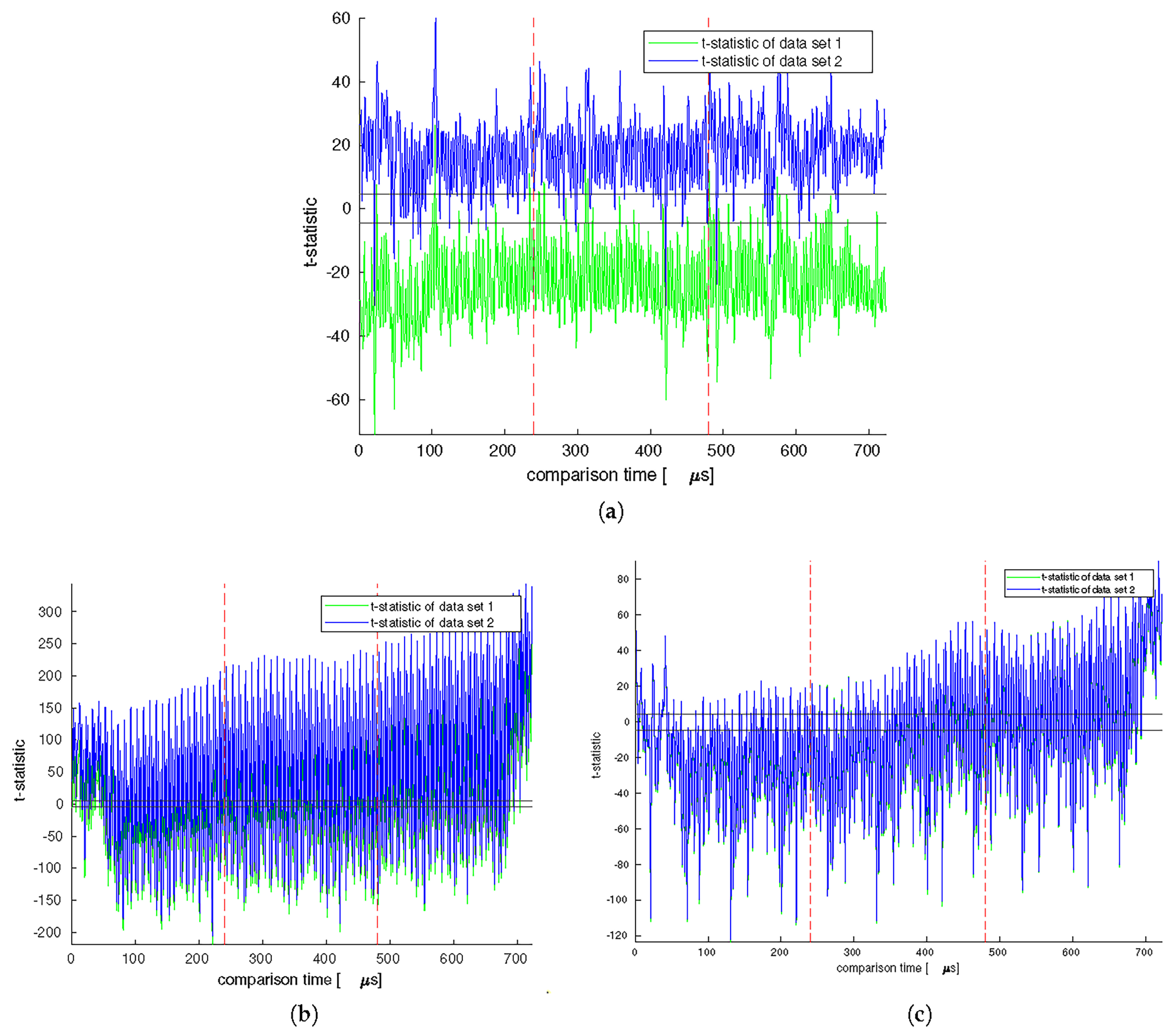
In order to analyze the data collected, we performed TVLA and two
t-tests for each experiment. To perform the
t-tests, we divided the collected datasets into two groups, with the first half being used for the first test and the second half being used for the second test. After dividing the data, we calculated the mean and standard deviation for each point in time and used these values to determine the t-statistic for Welch’s
t-test. The resulting test data is displayed in
Figure 6, with subfigures (a), (b), and (c) representing the results for AES, AES with a 128-bit Anti-SAT key, and AES with a 128-bit SFLL key, respectively. The encryption process for all the graphs can be observed between the two dotted red lines.
The circuits locked using Anti-SAT and SFLL were chosen based on the number of cryptographic key bits fed into the locking subcircuit. The Anti-SAT circuit had 64 bits, while the SFLL circuit had only 29 bits. For both locked circuits, we observed significantly higher leakage during the encryption process compared to the unlocked AES implementation. However, the t-values were slightly lower for the SFLL circuit. This can be attributed to the lower number of cryptographic key bits processed by the locking subcircuit, i.e., the 29 bits for SFLL vs. the 64 bits for Anti-SAT.
We investigated how logic locking affects the resilience of cryptographic circuits against side-channel attacks. Our results show that using logic locking schemes can potentially lead to the leakage of sensitive data in such circuits. Countermeasures such as masking can be implemented to prevent the leakage. If the high t-values are still observed even when masking is applied, this would further support our analysis. However, additional research is required to determine the effectiveness of these countermeasures in mitigating the issue.
6. LEDA: Attack Success Analysis
In this section, we explored why the proposed attacks are effective and under what conditions they produce the best results. We started by examining the pre-SAT RLL methods and their relationship with fault attacks. Both the considered methods induce perturbations into a cryptographic circuit. Our findings lead us to a constructive strategy for selecting the best incorrect locking key for our LEDFA attacks. All of the previous results were obtained using random-logic-locking keys. Following that, we looked into why LEDA performs well on circuits locked by post-SAT schemes compared to circuits locked using RLL. We have identified that the propagation of cryptographic key bits through the locking subcircuits added during logic locking is a crucial factor for successful attacks.
6.1. Locking Key Propagation for RLL
RLL inserts key gates at multiple locations within a circuit. Applying an incorrect locking key bit to any of the new inputs has a similar effect as a fault injection. While locking-enabled perturbation is easier to control, it is also more challenging than a fault attack at the same time. The equipment used for fault injection has limited spatial and temporal precision. Hence, an adversary who wants to inject a fault at a specific location may end up injecting a fault in another location or no fault at all. In contrast, by applying an incorrect locking key bit (or multiple bits), the corresponding key gate outputs will flip with certainty and perfect repeatability. On the other hand, perturbations on a desired circuit location are only possible if there is a locking key gate at that location. Even if a fault attack is unsuccessful, it can be repeated until it succeeds. However, the effects of locking circuitry are entirely deterministic.
In practice, an adversary can use the known fault attacks to apply LEDA. For instance, a well-known single-fault attack against AES-128 [
14] can only work if the flipped bits are limited to one byte in the cipher state after round 7. If there are faults elsewhere in the circuit, this attack would be invalidated. Since locking can easily flip multiple key gates, it is essential to consider the relationship between such simultaneous perturbations.
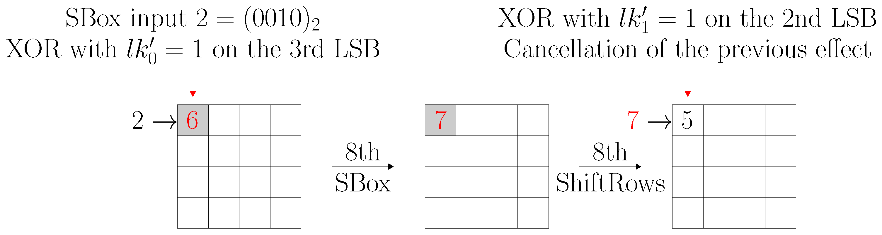
Figure 7 shows how two simultaneous bit flips can cancel out the effects of each other altogether, resulting in an unperturbed ciphertext that is useless for LEDA. The figure shows a part of “AES-64” that has locking key bits
and
driving key gates at the round 8 SBox input and ShiftRows output, respectively. If incorrect values are applied to both these locking key bits, the second induced change will fully compensate for the first one.
In general, it is unlikely for multiple incorrect logic-locking key bits to cancel each other out due to the nature of cryptographic schemes and their inherent diffusion properties. For example, with AES variants, it is improbable that an incorrect locking key bit will be fully canceled out after a MixColumns operation, as the effects are then propagated throughout an entire column of the intermediate state. The larger the operations, the lower the probability of this effect, but it cannot be ruled out entirely. However, from the attacker’s perspective, this is not a significant issue since the logic-locking key is a primary input of the circuit and can be easily changed for another incorrect logic key. In this work, the lower success rate of some LEDA attacks might be explained by the fact that the logic-locking keys were randomly selected.
On the other hand, let us consider the impact of the locking key bits placed in the most favorable positions for an adversary who can control the locking key bit values. As mentioned earlier, an incorrect cryptographic operation will affect the subsequent operations in the same way as a fault injection does. For example, suppose a collection of logic-locking key bits affects the operations of round 29 of LED. In that case, it will produce an incorrect intermediate output for LED round 29, which will impact the succeeding operations, similar to a fault injection at the start of round 30 of LED [
16].
We analyzed the gate-level netlist of an LED implementation that was logic locked using an 80-bit RLL-∧ locking key
. Our analysis led us to identify five locking key bits
that affect the operation of round 29 of LED. Suppose an adversary can control the locking key bits as primary inputs of the circuit. It implies they can easily choose a specific incorrect locking key
that flips the five locking key bits mentioned above. In our experiment, we performed one correct encryption and two incorrect encryptions using the correct locking key
and two incorrect locking keys
and
, respectively. Finally, we solved Equation (
4) (a special case of Equation (
3)) in order to obtain the cryptographic key
k.
Table 6 presents the results of running LEDA attacks on this logic-locked LED implementation with specific incorrect locking keys. For comparison, the table also includes the solve time and success rate of experiments with random incorrect locking keys from
Table 5. These results indicate that the success rate has improved from roughly one quarter to perfect. Moreover, while the average run time improvement may not seem significant, it includes instances that were hard to solve and timed out for random locking keys but were solved successfully for the handcrafted locking keys.
6.2. Cryptographic Key Bit Propagation in Post-SAT Locking
To explain the better performance of LEDA for post-SAT methods in
Table 5, we first note that they tend to introduce only one source of perturbation into the circuit. This eliminates the interference between different key gates, as discussed previously for RLL, and prevents the cancellation effect from occurring. The source is driven by the locking subcircuit, which is composed of functions
g and
for Anti-SAT and the restore unit for SFLL, as shown in
Figure 3. As explained in
Section 2.1.2, the inputs to this subcircuit are known as the “tree input set”, and the location where the subcircuit is inserted into the locked circuits is referred to as the “root”. When the tree input set is randomly determined, the algorithm tends to insert the root closer to the end of the circuit. A parallel can be drawn between LEDA and fault attacks since the substitution–permutation networks are most vulnerable to fault injections in their last 2–3 rounds. Therefore, post-SAT locking techniques have a slightly higher chance of introducing a well-controllable perturbation in a location that is critical for cryptanalysis.
A further explanation is that during cryptanalysis, the locking subcircuit plays an important role. It is simpler and much smaller compared to the actual cryptographic circuit. For instance, in the case of Anti-SAT with a 64-bit locking key, a logic-locking block consisting of only 67 gates is inserted into an LED implementation that otherwise has 26,104 gates. The subcircuit has 32 inputs selected from the primary inputs of the circuit, which include bits of the plaintext and the cryptographic key. This creates a new path between selected bits of the cryptographic key and the circuit outputs passing through the locking subcircuit, the root and the remaining logic between the root and the outputs. This path will usually be much shorter than the existing paths between the cryptographic key and the outputs, and it goes through circuitry that was not designed with any cryptographic properties in mind. LEDA incorporates the new path in the CNF, and as a result, the SAT solver will be more effective.
In order to test our hypothesis, we ran NEOS multiple times to generate different locked circuits for Anti-SAT and SFLL. We used a 64-bit and a 128-bit locking key for both schemes. It is important to note that we deviated from our threat model in this experiment—the adversary was given a locked circuit and did not have the ability to influence the location where the locking circuitry would be added. For each run, we determined the number of cryptographic key bits in the tree input set, denoted by #CKB. The results are presented in
Table 7. We discovered a clear trend: cases with more cryptographic key bits in the tree input set were consistently and systematically faster, while cases with only a few #CKB timed out. In some cases, the run time of successful attacks increased exponentially with #CKB. This is intuitive if we assume that LEDA can easily recover the key bits from the tree input set, and the remaining bits must be brute-forced. However, this effect is not universal; there may still be cryptographic key bits in the tree input set that are difficult to recover.
One notable aspect that stands out from the findings presented in
Table 7 is the remarkable effectiveness of LEDA against SFLL, which previously exhibited poor results as demonstrated in
Table 5. When comparing Anti-SAT and SFLL, we observe similar timeout behavior and run times for comparable #CKB. However, in this case, LEDA appears also to be effective against SFLL, particularly when a sufficient amount of #CKB is present. The vital distinction between Anti-SAT and SFLL is that the former only allows the primary inputs of the circuit in the tree input set, while the latter permits intermediate wires as well. Consequently, the likelihood of encountering a cryptographic key bit among the primary inputs is significantly higher than among all the signals, resulting in a much higher average #CKB for Anti-SAT. Therefore, we can conclude that the ineffective performance of LEDA against SFLL, as shown in
Table 5, was most likely due to a low #CKB in randomly generated locking instances.
7. Proposed Countermeasure for LEDA
In
Section 6.2, we evaluate attack success rates for LEDA, and based on it, we propose a strategy to prevent the propagation of cryptographic key bits to the primary outputs through the smaller locking subcircuits. The results of our experiments, presented in
Table 7, indicate that the success rate of LEDA is highly dependent on the presence of cryptographic key bits in the tree input set. To achieve better security levels, circuit designers utilizing logic locking schemes for cryptographic circuits must carefully consider the placement of cryptographic key bits and avoid introducing them directly into the locking subcircuits.
In order to evaluate the effectiveness of our proposed method, we conducted a series of experiments where we modified the post-SAT logic locking schemes in NEOS. Specifically, we excluded cryptographic key bits from the set of eligible primary inputs for the tree input set. Instead, we derived the tree input set exclusively from plaintext bits or intermediate wires. We then generated a set of locked cryptographic circuits using Anti-SAT and SFLL schemes. We verified that none of these circuits contained any cryptographic key bits within the tree input set.
Afterwards, we proceeded to conduct LEDA attacks on each circuit and compared the results to those obtained from previous experiments. As indicated in
Table 8, our proposed countermeasure proved to be highly effective, reducing the success rate to nearly zero in most cases. These results are in stark contrast to the 100% success rate observed in
Table 7. However, we did observe a few successful attacks in certain scenarios, such as five successful attacks on PRESENT locked using a 64-bit Anti-SAT locking key when the attack formula was constructed using 10 incorrect logic-locking keys.
Furthermore, we also noted that the average solve time for these successful attacks was significantly longer compared to the results observed in both
Table 5 and
Table 7. Overall, these findings suggest that our proposed method is a highly effective countermeasure against LEDA attacks, although further improvements may still be possible in specific scenarios.
8. Conclusions and Future Work
We proposed two attacks that utilize the presence of logic-locking circuitry for fault-based (LEDFA) and classical (LEDA) cryptanalysis. The reason the attacks are effective is that the improperly unlocked circuits retain access to the cryptographic key while implementing functions that may have less cryptographic strength. Furthermore, new propagation paths that are introduced by the locking circuitry can make cryptanalysis significantly simpler. The attacks continued to work in our experiments even when random selections of incorrect locking keys were made. The success rate dramatically increased when optimized locking keys that caused disturbances in the vicinity of circuit locations susceptible to known fault attacks were used. We suggest prohibiting the direct feeding of cryptographic key bits into locking subcircuits. Our findings demonstrate how the circuits locked using the modified logic locking schemes are much more resistant to LEDA.
In addition, we investigated side-channel leakage of multiple logic-locked AES implementations. This first assessment using TVLA methodology, as shown in
Section 5.3.3, showcases interesting leakage patterns compared to a standard AES implementation. Our results suggest that locking has a non-negligible influence on information leaked from the implementation. Dedicated SCA countermeasures are necessary in the case of locked and unlocked cryptographic circuits alike. Such protections must be verified to be effective under different locking keys. This is, however, out of scope for this paper, but investigating protected circuits would be interesting as a continuation of this work.
Despite not being created with cryptographic circuits in mind, no previous work has explicitly excluded logic-locking techniques from its purview. Because of this, critical system designers might wish to use logic locking to add an extra degree of security, which, unfortunately, would weaken the systems. This work is the first to use quantitative analysis to both identify and validate the vulnerability introduced by such schemes. The results of this work suggest that using logic locking in cryptographic circuits is not safe. The designer must avoid adding key gates to crucial locations where fault attacks could occur (e.g., the last 3–4 rounds in substitution–permutation networks). Furthermore, future locking schemes can be expanded with the ability to identify an extended use of incorrect locking keys, in a manner similar to identifying fault attacks or attempted tampering.


