2. Compliant Joint Design
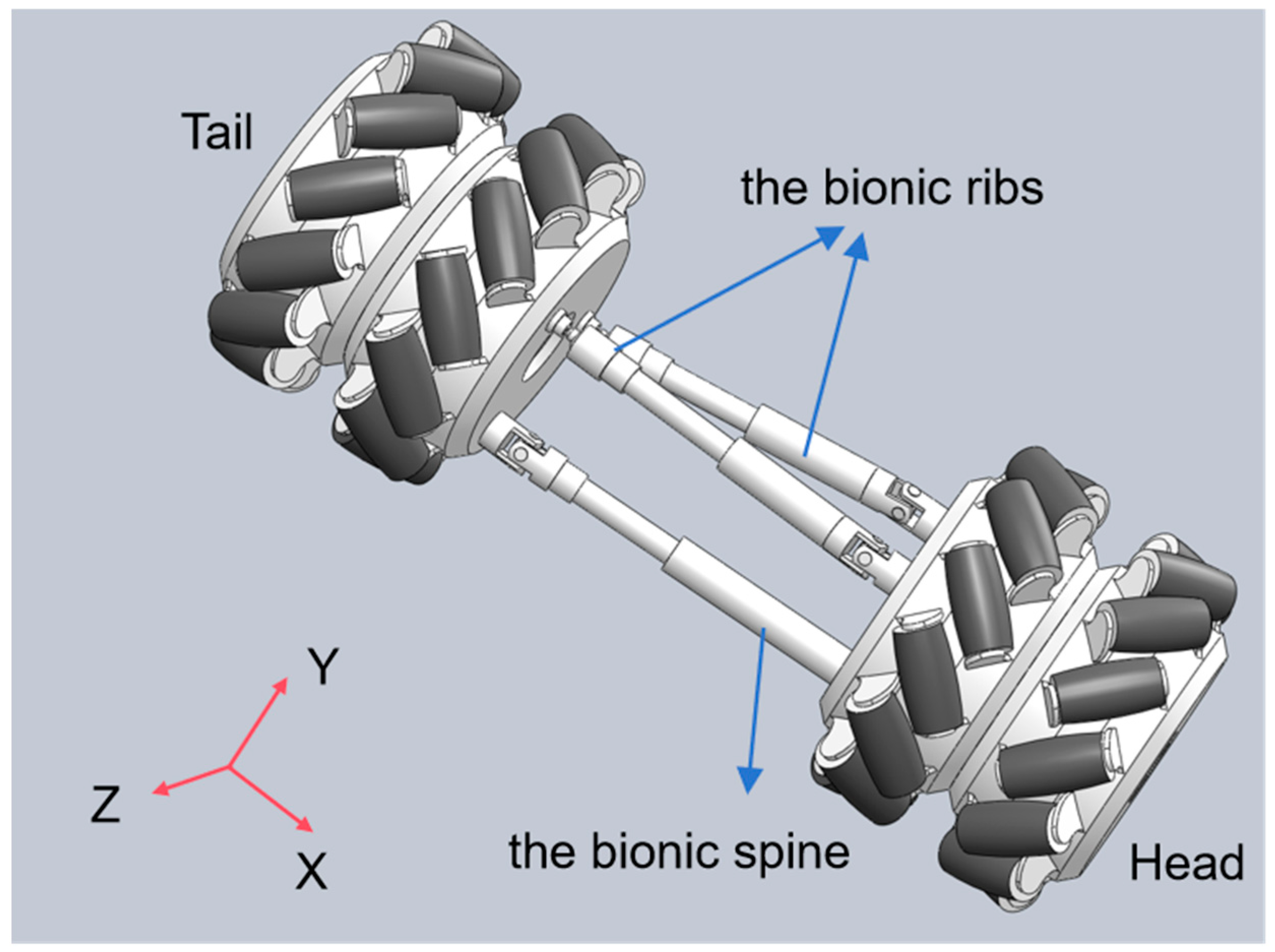
To enhance the adaptability of snake-like robots to complex environments and enable multimodal motion similar to biological snakes, this paper proposes a three-degree-of-freedom (DOF) compliant joint design. This design aims to mimic the skeletal flexibility of biological snakes, as shown in
Figure 1. When the length of the constraint chain and the bionic spine remains unchanged, the pitching motion of the snake-like robot can be achieved by controlling the two bionic ribs chains to extend and retract the same amount. Conversely, steering is realized by controlling the two bionic ribs chains to extend and retract different amounts. When all three chains undergo simultaneous extension and contraction, the overall expansion and contraction motion of the joints is realized. As shown in
Figure 1, extension and contraction achieve movement in the X-axis direction, steering achieves rotation along the Y-axis, and pitch achieves rotation along the Z-axis direction, achieving a total of three degrees of freedom.
The joint structure integrates Mecanum wheels with parallel mechanisms, providing the necessary flexibility for diverse locomotion modes. The Mecanum wheel adopts a radial roller structure, supporting compound movement in both longitudinal and transverse directions. It can achieve gait such as lateral fluctuation without the need for the fuselage to turn, breaking through the limitations of traditional wheel systems. Its structure decouples the degrees of freedom of motion, mimics the flexibility of snake-like ribs, actively controls the rolling direction through the UPS mechanism, and optimizes energy transfer with anisotropic friction characteristics, thereby enhancing the propulsion efficiency. These are precisely the capabilities that conventional rigid wheels, omniwheels, or passive rollers are inherently incapable of achieving. Kinematic and dynamic models were developed to study the forces involved and to characterize the robot’s motion, ensuring the design can be optimized for efficient locomotion in a variety of terrain types.
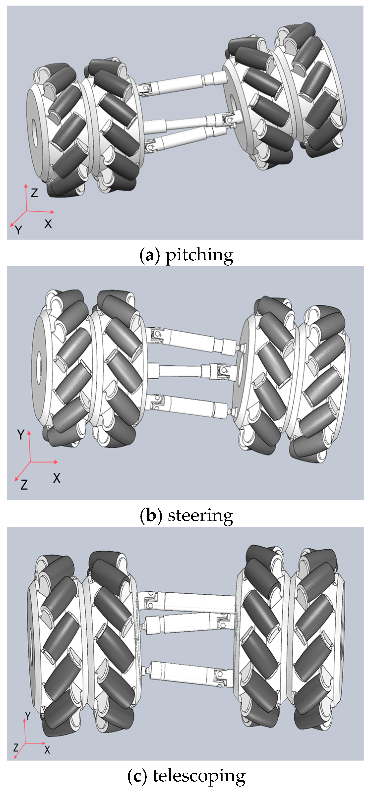
The snake-like robot features a modular structure with identical joints. As shown in
Figure 2, three motor drive units are arranged along three linear struts, enabling the joints to perform three distinct motions: pitching, steering, and telescoping. This decentralized design not only strengthens the overall structure but also enhances load capacity.
As illustrated in
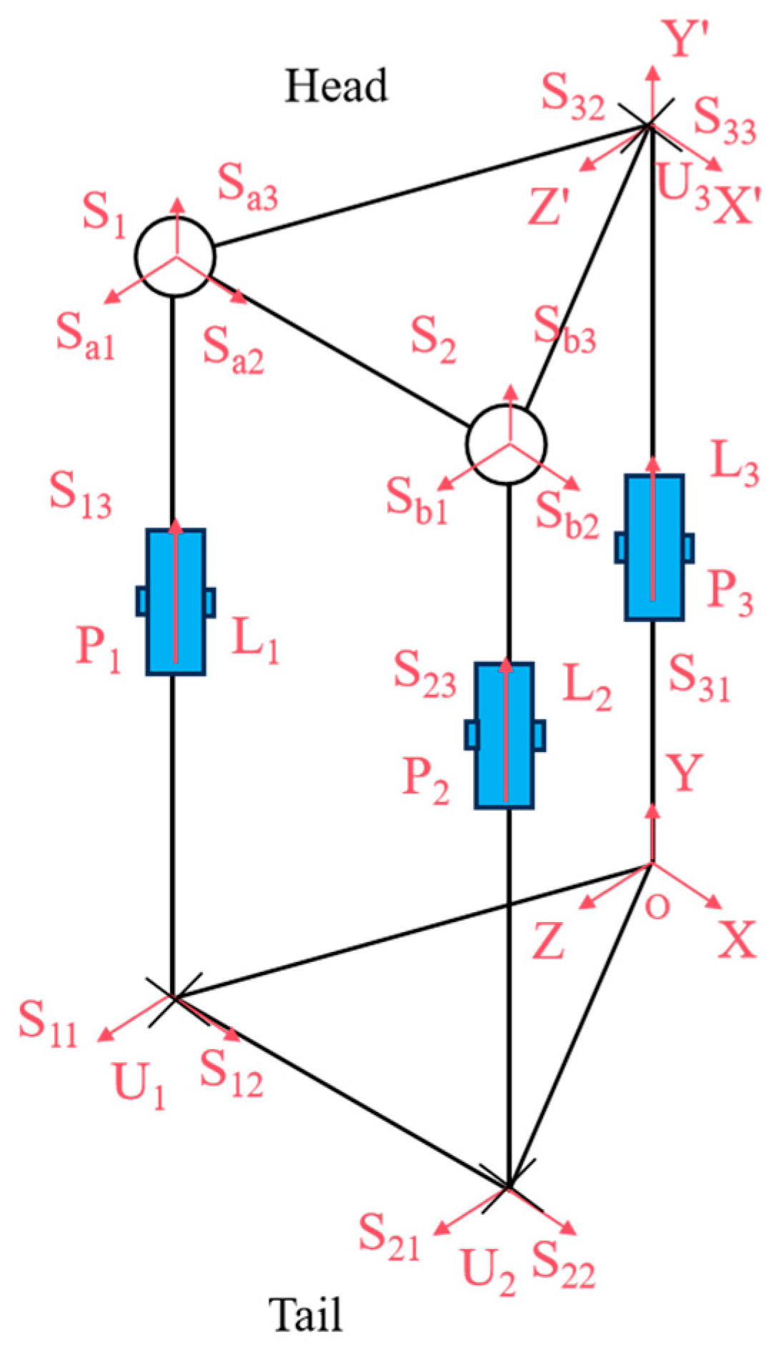
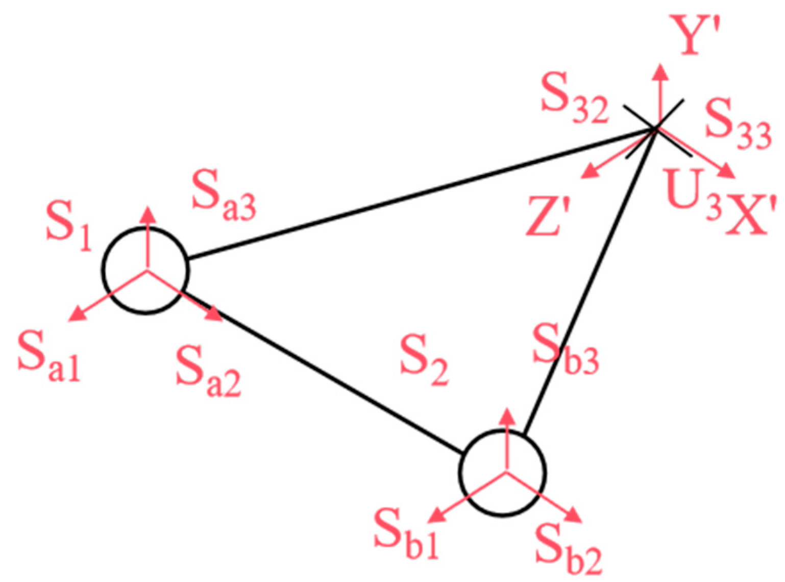
Figure 3, we analyzed the kinematic mechanism of the designed flexible joint. This mechanism mimics the rib array distribution and musculoskeletal dynamics found in snakes, achieved through the synergistic configuration of the mobile platform and the prismatic joint. The joint structure consists of two symmetric Hooke’s hinge–cylindrical pair–ball joint mechanisms, which simulate the ribs. Here, U represents Hooke’s hinge, S denotes the ball joint, and P stands for the cylindrical pair. Two symmetric prismatic legs are attached to the ball joint, which effectively counteract the torque perpendicular to the kinematic platform. Additionally, a third strut simulates the bionic spine, providing essential core support. The decoupled control of yaw and pitch motions is facilitated by a specially designed Hooke’s hinge cross-axis system, ensuring smooth motion transfer while maintaining joint length stability.
Within the UPS mechanism, Ui and Si (I = 1, 2) denote the centers of the Hooke hinge and ball joints, respectively. The constraint center of the constrained-Hooke hinge mechanism is O, and the center of the Hooke hinge is U3. The moving platform is represented by triangle ∆S1S2U3, while defines the stationary platforms, and ∆U1U2O forms the stationary structure, where .
A global coordinate system O-XYZ is established with O as the origin, where , , and . A moving coordinate system is then defined on the moving platform, U3-X’Y’Z’, where X’Z’ refers to the direction of the two axes along the Hooke hinge, respectively.
According to spiral theory, any spatial motion can be decomposed into a rigid body rotation around a specific axis and a translation along another axis. The spinor system of motion for joint chain
U1P1S1 can then be expressed in global coordinate system
O-
XYZ as
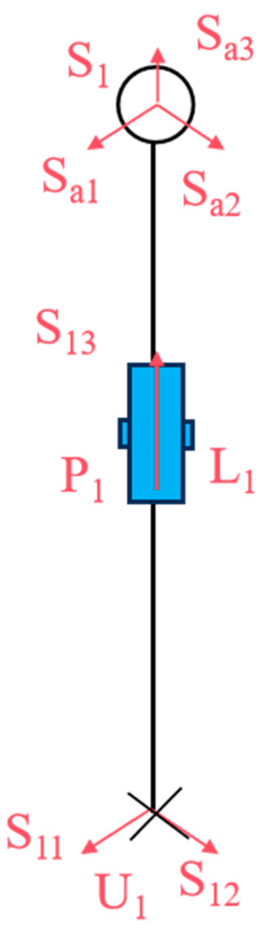
As illustrated in
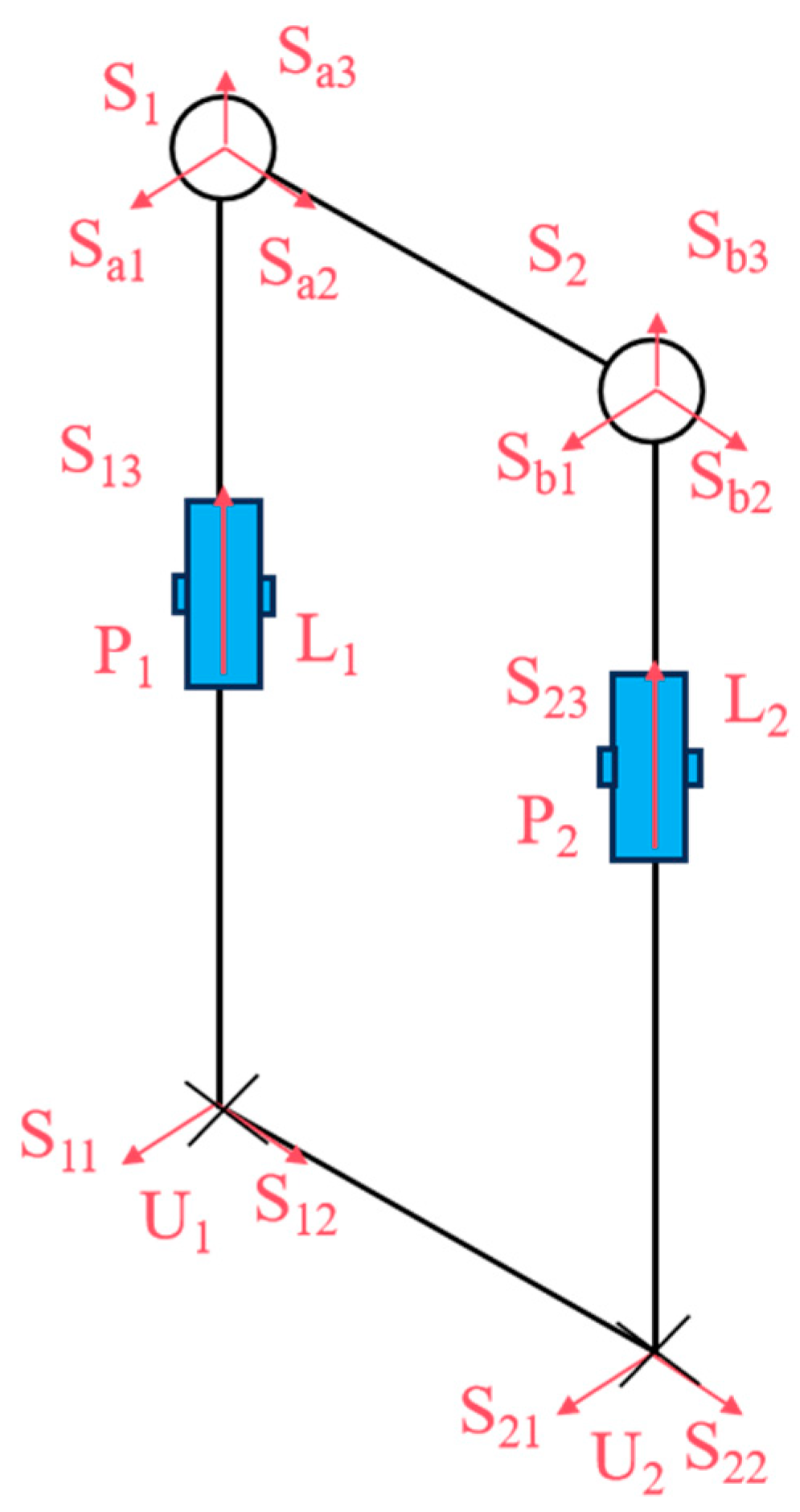
Figure 4, let
S11 and
S12 represent the rotations of the two rotating pairs in the Hooke hinge,
S13 denote the rotations of the cylindrical moving pair, and
Sa1,
Sa2, and
Sa3 represent the rotations of the three rotating pairs in the ball joint.
θ1 and
φ1 denote the rotation angles of the two rotating pairs of the Hooke hinge, respectively, while
l1 represents the length of
U1S1.
Since the first spin of Sl1 is the empty set (i.e., it does not constrain the moving platform), another articulated chain U2P2S2 undergoes the same kinematic analysis as the first chain.
In the global coordinate system
O-
XYZ, the position of
U3 is denoted as (0,
l3, 0), where
l3 is the length of
OU3. The rotational quantity of the motion of the Hooke hinge in the
OU3 chain can be expressed as
where
β is the angle of rotation around the
X’ axis in Hooke hinge joint
U3.
Since the two UPS chains do not impose constraints on the moving platform ∆
S1S2U3, as shown in
Figure 5, the motion of the moving platform follows the same rotational behavior as described by Equation (2). Consequently, the moving platform boasts two rotational degrees of freedom, with its center of rotation coinciding with the Hooke hinge
U3 center.
The reciprocal rotation of the moving platform relative to
S13 and the fixed platform can be expressed as
From Equation (3), it is evident that the rotation of the OU3 chain intersects with the motion rotations S31 and S32 at point U3, while is perpendicular to both S31 and S32. The OU3 chain generates constraints in the X’, Y’, and Z’ directions, as well as a rotational constraint around the Z’ axis. However, the two UPS chains do not impose any movement constraints on the platform. This indicates that the primary constraints arise from the OU3 chain, which aligns with the movement constraints of the spine in biological snakes.
The snake-like compliant joint movable platform exhibits the same two rotational degrees of freedom as the Hooke hinge, specifically the pitching and steering degrees of freedom. In this study,
P1 and
P2 of the UPS chain (the bionic ribs), as shown in
Figure 6, were selected as the two driving elements to actuate the motion rotations
S13 and
S23 of the moving platform.
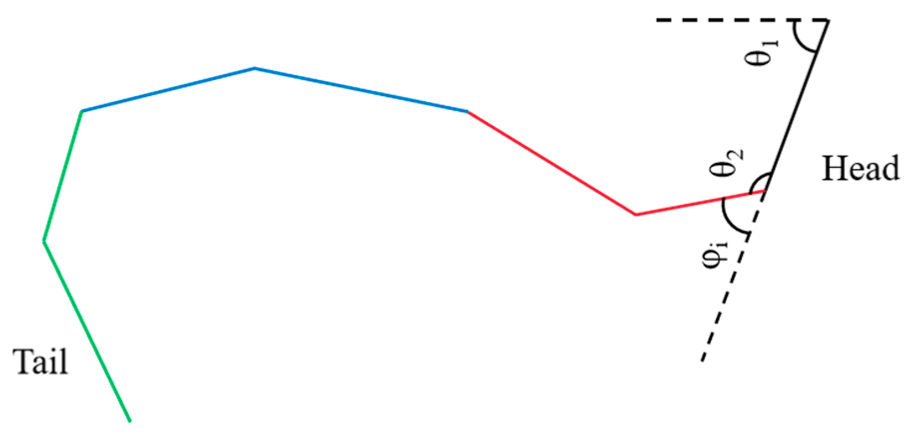
Hirose’s study [
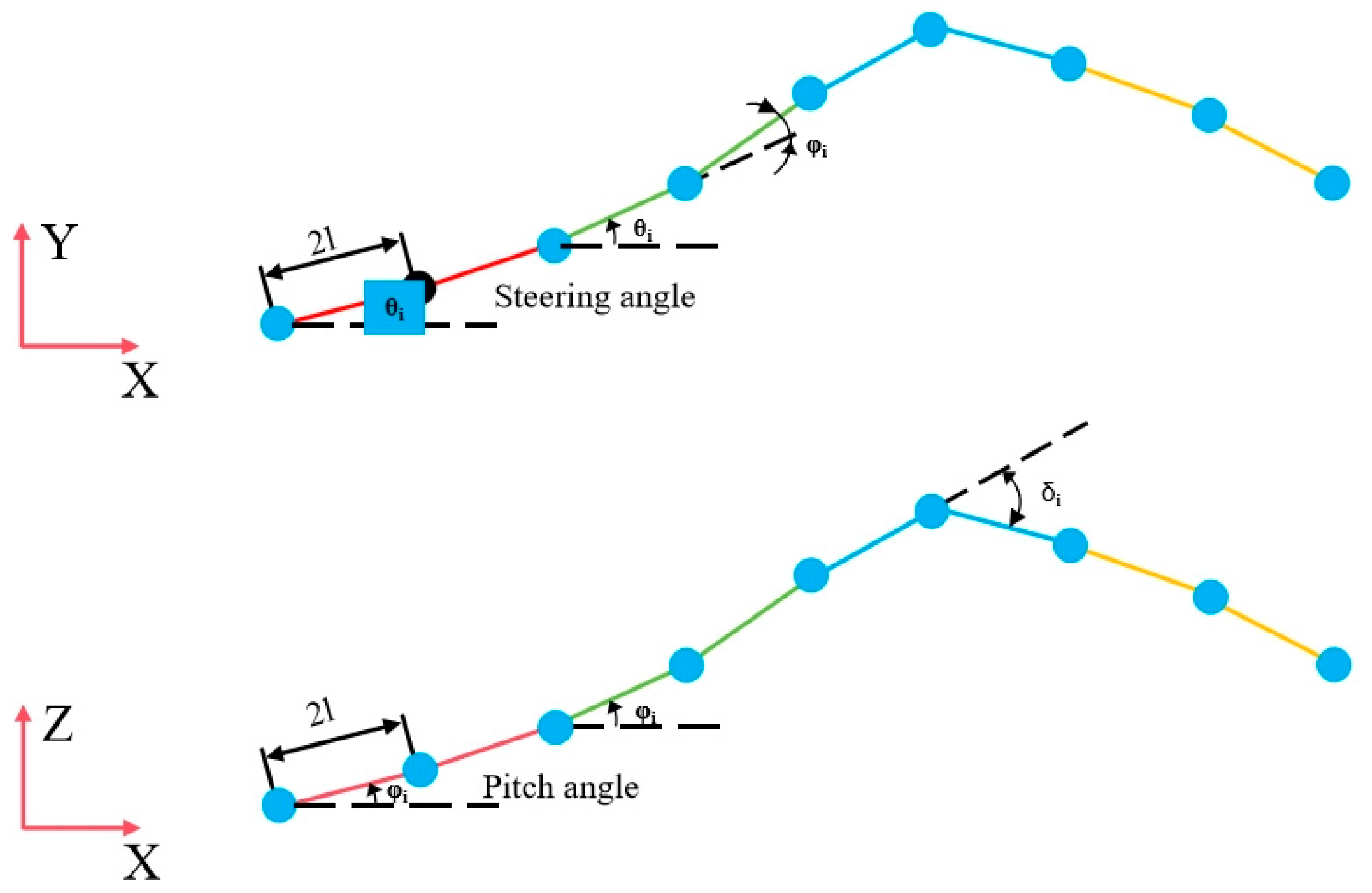
10] suggests that biological snakes achieve locomotion by twisting their bodies, and their trajectory can be modeled as a trigonometric curve. The direction of movement corresponds to the change in the angular axis of the sine function, as illustrated in
Figure 7.
The motion trajectory can be described as
In this case, a, b, and c represent the parameters of the snake’s motion curve, and s represents the arc length in the forward direction. Equation (4) presents a continuous curve; however, to ensure effective motion control of the snake-like robot, the curve equation necessitates further refinement.
To attain control of the snake-like robot, the continuous control angles of the rotating joints need to be ascertained:
Let φi represent the control angle of the first segment, and . When b = 2π, the robot completes one full motion cycle, and the control angle can be expressed as φi = θi+1 − θi, where θi is the angle between the joint and the X-axis.
Angle
θ1 can be derived when the snake-like robot completes one full gait cycle:
where
K is the cycle parameter determined by the number of joint modules in the snake-like robot. The amplitude and wavelength of the robot’s motion can then be calculated as
Here, l denotes the half-length of the joint, A is the maximum theoretical amplitude of the snake-like robot, and the robot’s actual motion should follow the trajectory of its center of mass.
By analyzing the motion control of individual joints, the linear actuator angle control equations for each supple joint of the snake-like robot can be derived:
where
and
are the lengths of the two rods connected to the
i-th joint,
l0 is the initial length of the rods,
φi is the horizontal deflection angle of the
i-th joint, and
a is the distance between the two rods inside the joint. The pitch angle of the joint is controlled as
where
δi is the pitch angle of the
i-th joint.
According to the equations of motion, controlling the extension and retraction lengths of the three rods of the flexible joints allows for the realization of expansion, contraction, steering, and pitching movements of a single joint. Specifically, when the length of the constraint chain OU3 remains unchanged, the pitching motion of the snake-like robot can be achieved by controlling the two UPS chains to extend and retract the same amount. Conversely, steering is realized by controlling the two UPS chains to extend and retract different amounts. When all three chains extend and contract simultaneously, the joint undergoes overall expansion or contraction.
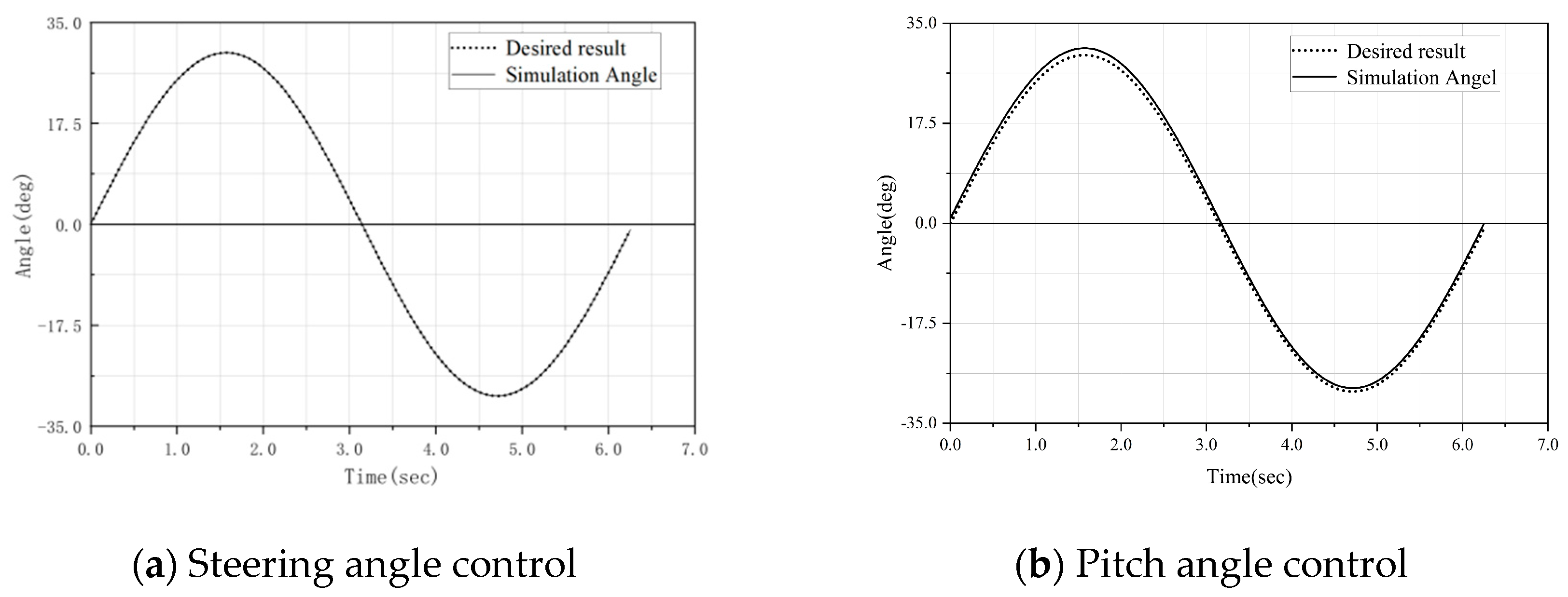
The simulated angles during the motion of the snake-like robot can be obtained through Equations (8) and (9), and were compared with the desired sinusoidal fluctuation motion trajectory. As shown in
Figure 8, it can be observed that the steering simulation angles of the robot joints are closely aligned with the desired results and are distributed very uniformly. However, as shown in
Figure 8b, with the increase in the pitch angle, the contact distance between the simulated angle and the actual expected angle becomes larger, and the resulting error becomes more obvious.
3. Adaptive Gait Control via CPG Network
3.1. Dual-Chain CPG Architecture
Central pattern generator (CPG) networks, which utilize specialized neural oscillators to generate gait signals for snake-like robots, offer significant advantages in environmental adaptability through their built-in feedback mechanisms. However, designing these models and adjusting their parameters remain challenging tasks.
To address these challenges, we propose a novel dual-chain CPG architecture based on Hopf neural oscillators. This design takes advantage of the periodic nature of serpentine locomotion to achieve three key benefits:
1. Multimodal Gait Generation: The network generates a variety of locomotion patterns while reducing the dimensionality of control parameters, a limitation in single-chain models where high-dimensional outputs require complex parameter tuning. A small set of state variables can govern high-dimensional joint motions, contrasting with traditional single-chain models that often rely on the independent adjustment of each joint.
2. Enhanced Dynamical Properties: The use of natural rhythmic signals for joint motion control, mimicking biological neural dynamics and avoiding the discontinuous signals of non-oscillatory models’ faster convergence rates to stable gaits, significantly reduces the convergence time compared to single-chain Hopf networks. This simplified parameter transitions via diffusive coupling, whereas a traditional single-chain CPG suffers from abrupt changes in control signals during gait switching.
3. Implementation Efficiency: The dual-chain architecture significantly reduces computational complexity during gait parameter optimization, making it more efficient in real-time computation than single-chain models with equivalent performance. This efficiency addresses the computational bottleneck of traditional high-dimensional CPG networks.
The kinetic equation for the Hopf neural oscillator is given by
Among them, x = (a,b)T, rx is the radius of the limit circle range, v is the convergence speed that affects the output value to converge to the limit circle, ac and bc determine the center position within the limit circle range, ε is the bifurcation parameter of the neuron, and ζ = 1 is set in this paper.
Here, axi is the output value of the neural oscillator, and ai and bi offsets are determined by ac,i and bc,i, respectively. ac,i and bc,i are the core control parameters, which are the offset parameters of the horizontal and vertical centers, respectively, determining the reference position of the oscillator on the horizontal axis (A-axis) and the vertical axis (B-axis). The output value of Hopf’s neural oscillator can be stabilized to converge to the a-b plane, where a and b are sinusoidal curves after the stabilization of the output value.
In order to realize the three-dimensional motion control of the snake-like robot in this study, a two-chain Hopf neural oscillator network was designed based on the Hopf neural oscillator network of reference [
30]. The dynamics equation of its first
i oscillator is expressed as
where x
i = [a
xi,b
xi]
T and y
i = [a
yi,b
yi]
T are the outputs of the oscillator in the horizontal and vertical directions, respectively, and
axi and
bxi represent the serpenoid composite curves of the control signals for the
i-th steering joint and the
i-th pitch joint, respectively.
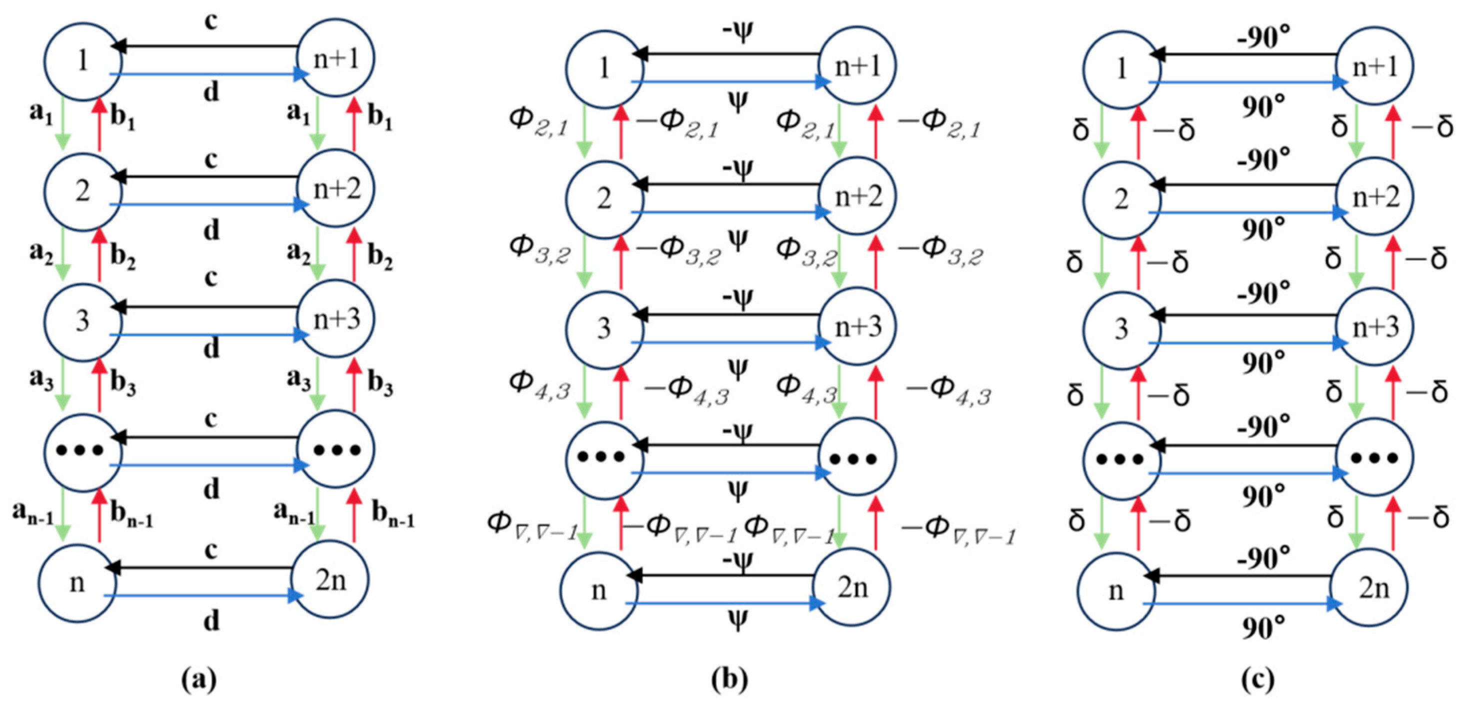
The structure of the dual-chain Hopf neural oscillatory network is shown in
Figure 9. The left green chain and right red chain of Hopf oscillators generate reference curves for horizontal and vertical joint motions, respectively. Here,
a,
b,
c, and
d are the weights between neighboring neurons, and
δ represents the phase difference between adjacent neurons, which varies depending on the specific motion being executed.
The dual-chain CPG neural oscillatory network is composed of 2
n Hopf oscillators. The left CPG chain is numbered 1 to
n, controlling the joint movement in the horizontal direction of the snake body, and the right chain is numbered from
n + 1 to 2
n, controlling the joint movement in the vertical direction of the snake body. All oscillators are connected via diffusive coupling. Various gaits of the snake-like robot can be achieved by adjusting the phase difference in the CPG network. In this study, the lateral undulating gait was simulated using the parameters in
Table 1.
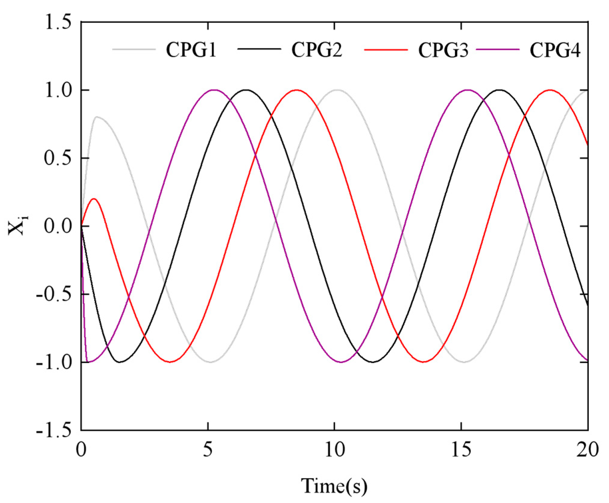
Figure 10 illustrates how the output signals of the four CPG oscillators change when the phase difference
ϕh,ij = π/3.
To explore the relationship between the parameters and the CPG output signals, we examined the effects of the phase difference
ϕh,ij and the amplitude
αh using the step-switching method.
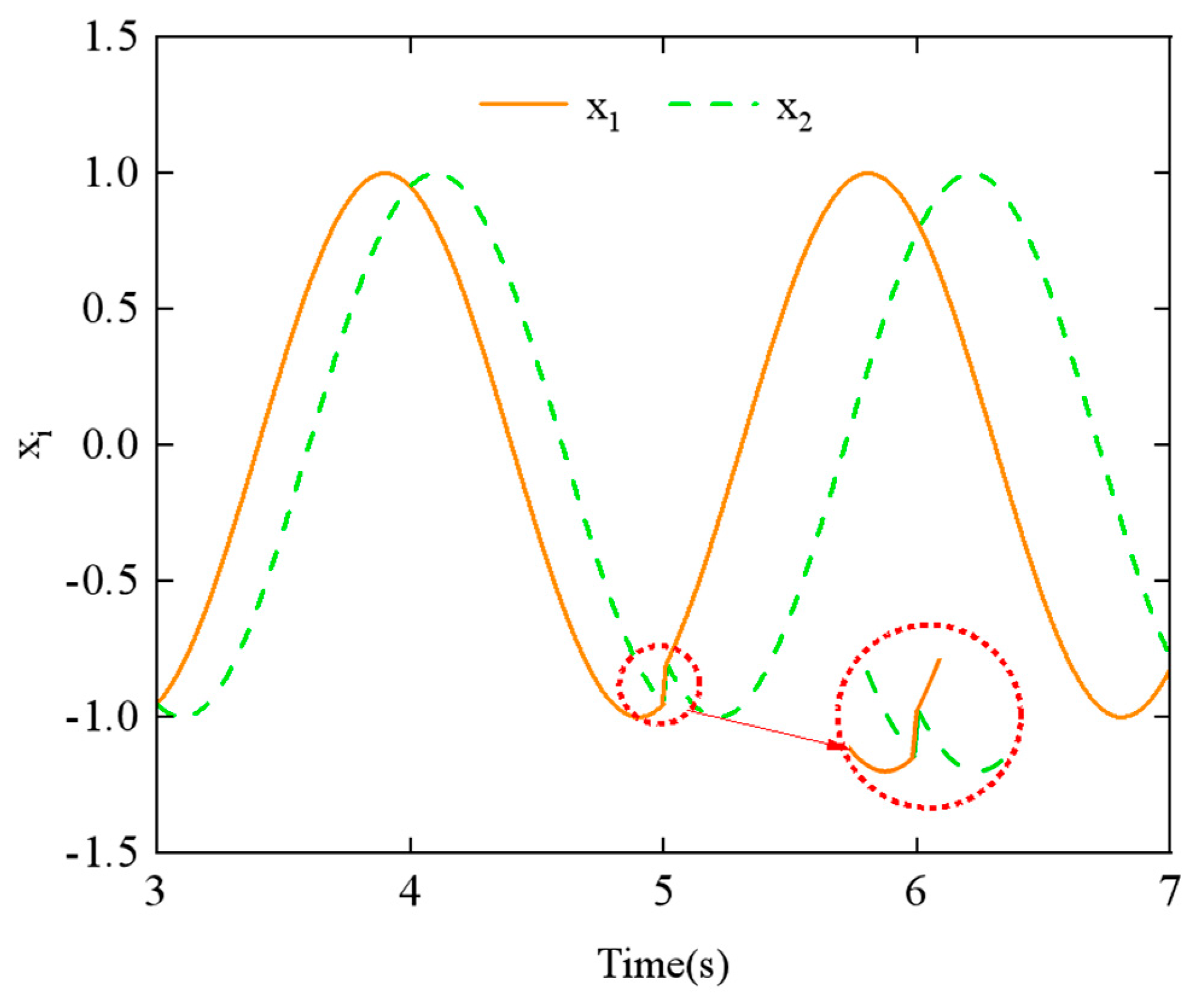
Figure 11 shows the simulation results of phase difference
ϕh,ij at
t = 5 s, with a change from π/4 to π/2. Similarly,
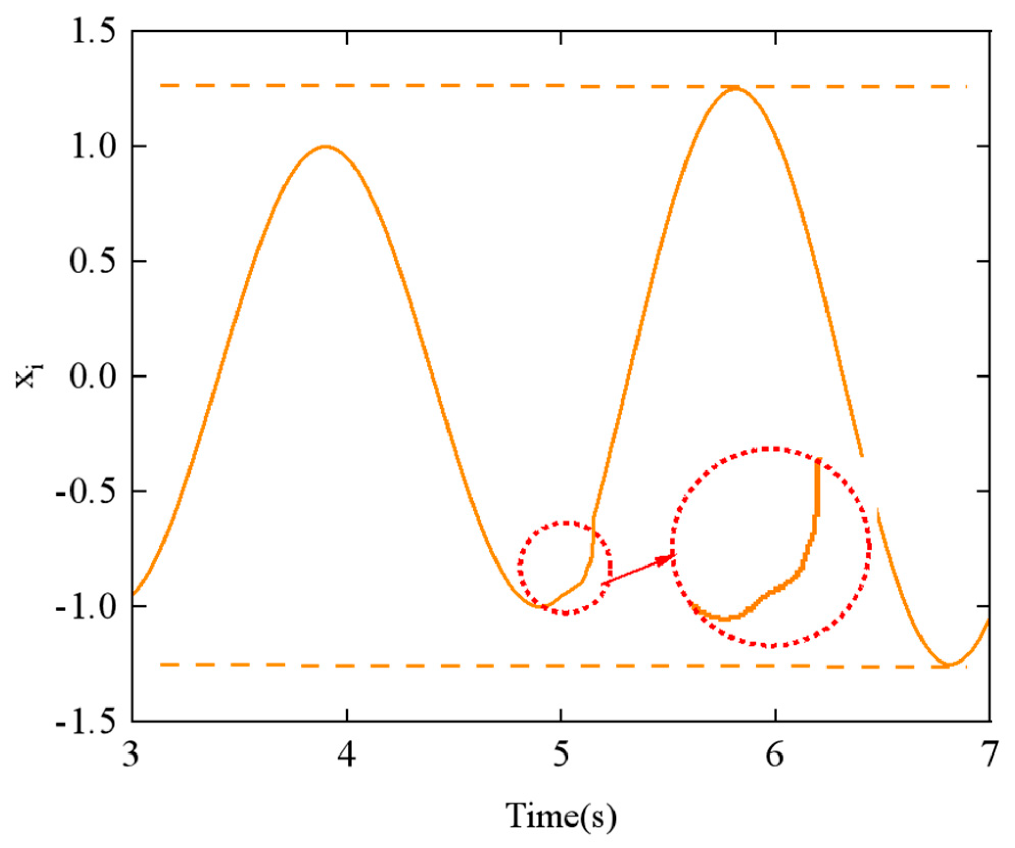
Figure 12 displays the simulation results of amplitude
αh at
t = 5 s, with a change from π/6 to π/3.
From
Figure 11 and
Figure 12, it can be observed that the CPG output exhibits abrupt and discontinuous curves when the parameters are varied. Such aberrant or discontinuous control signals can lead to uncoordinated motion in the motors of the snake-like robot, potentially causing damage to both the motors and the joint structure. To prevent this issue, we investigated methods to achieve the smooth switching of gait parameters within the CPG network.
3.2. Gait Transition Smoothing
Evaluating curve continuity and smoothness mainly depends on parametric continuity (C
n) and geometric continuity (G
n); C
n and G
n denote the n-th order parametric continuities. Geometric continuity ensures geometric consistency, while parametric continuity demands underlying parameter continuity [
31]. In this study, it was essential to guarantee that the smoothness of the snake-like robot’s motion was at least (C
2) and (G
2).
To analyze the C
1 order continuity of the robot’s motion, we simplified the CPG network to a single-phase oscillator model, which is mathematically represented as follows:
where
θi is the phase of the
i-th oscillator,
θj is the phase of the
j-th oscillator,
υi is the intrinsic frequency of the oscillator, and
ωij represents the coupling weight between neighboring oscillators. According to [
32], for smooth output signals in a phase oscillator model, it is crucial that
ωij exceeds
υi.Thus, the oscillation model in Equation (12) is enhanced by introducing a parameter (
τ), which simultaneously controls both
ωij and
υi, as follows:
where
ϕij is the phase difference. To ensure effective control of the CPG output, the value of
τ should remain less than 1. If
τ > 1, the output performance is compromised. By adjusting
τ, smooth output can be achieved while maintaining the stability of
υi and
ωij.
The output of a single oscillator is defined as
where
xi represents the output signal (i.e., the joint angle), and
A is the amplitude.
As per the two-chain CPG network in the previous section, all oscillators operate with an identical phase parameter
ϕ to create symmetric joint motions for the snake-like robot. The total phase difference is set as (−
ϕ) for downward motion and
ϕ for upward motion.
Representing the total driven joints of the robot,
n is subject to a total phase difference of 2π. Accordingly, the total joint movements,
N, of the snake-like robot can be presented as
By varying the phase difference
ϕ, different gaits of the snake-like robot can be realized, which is mathematically represented by
The first-order continuity C
1 of the CPG network output can be derived from Equation (13) and expressed as
Deriving Equation (18) again yields the parametric continuity evaluation C
2, with the following expression:
However, for Equations (18) and (19), in assuming that the phase transition occurs from
ϕij = ϕ1 to
ϕij = ϕ2, neither equation proves to satisfy parametric continuity C
1 and C
2. As shown in
Figure 11, there is a noticeable discontinuity in the CPG network’s output curve when the phase difference parameter is switched, which also fails to demonstrate the geometric continuity of the switching process.
To achieve smooth gait transitions, Qiao et al. [
33] designed a double-chain CPG network to generate the control signals for the snake-like robot and proposed a method based on linear segmented functions for gait smoothing. In this paper, we propose an improved linear function algorithm for gait smoothing conversion, introducing a linear bipolar function as the activation function. This modification ensures that the output signal changes linearly during the phase difference switching process.
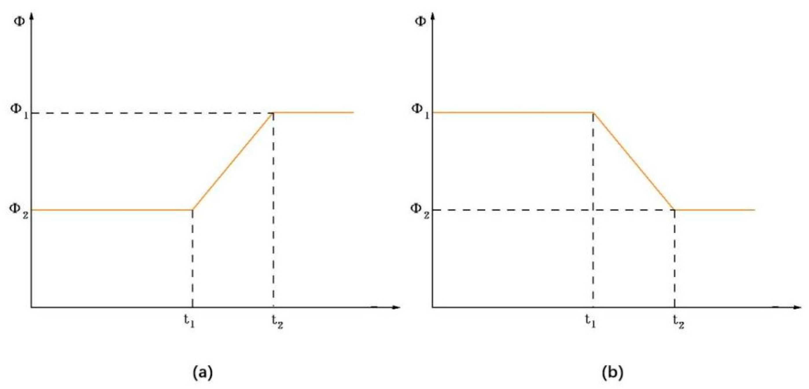
Figure 13 illustrates the variation in phase difference
ϕ over the time interval
t1 to
t2.
As an example of
ϕ reduction, the phase difference
ϕ as a function of time
t is described by a linear bipolar function:
where
,
N1 and
N2 represent the number of movements of the joints,
ϕ2 and
N2 are pre-determined values, (
t2 −
t1) is the switching time for the phase difference from
ϕ1 to
ϕ2, and
t1 is the moment when the phase difference begins to change.
With the substitution of Equation (20) into Equations (18) and (19), it is straightforward to show that the output curves exhibit C1 and C2 continuity of the parameters around (t = t1) and (t = t2), meaning that the parameter smoothing is improved.
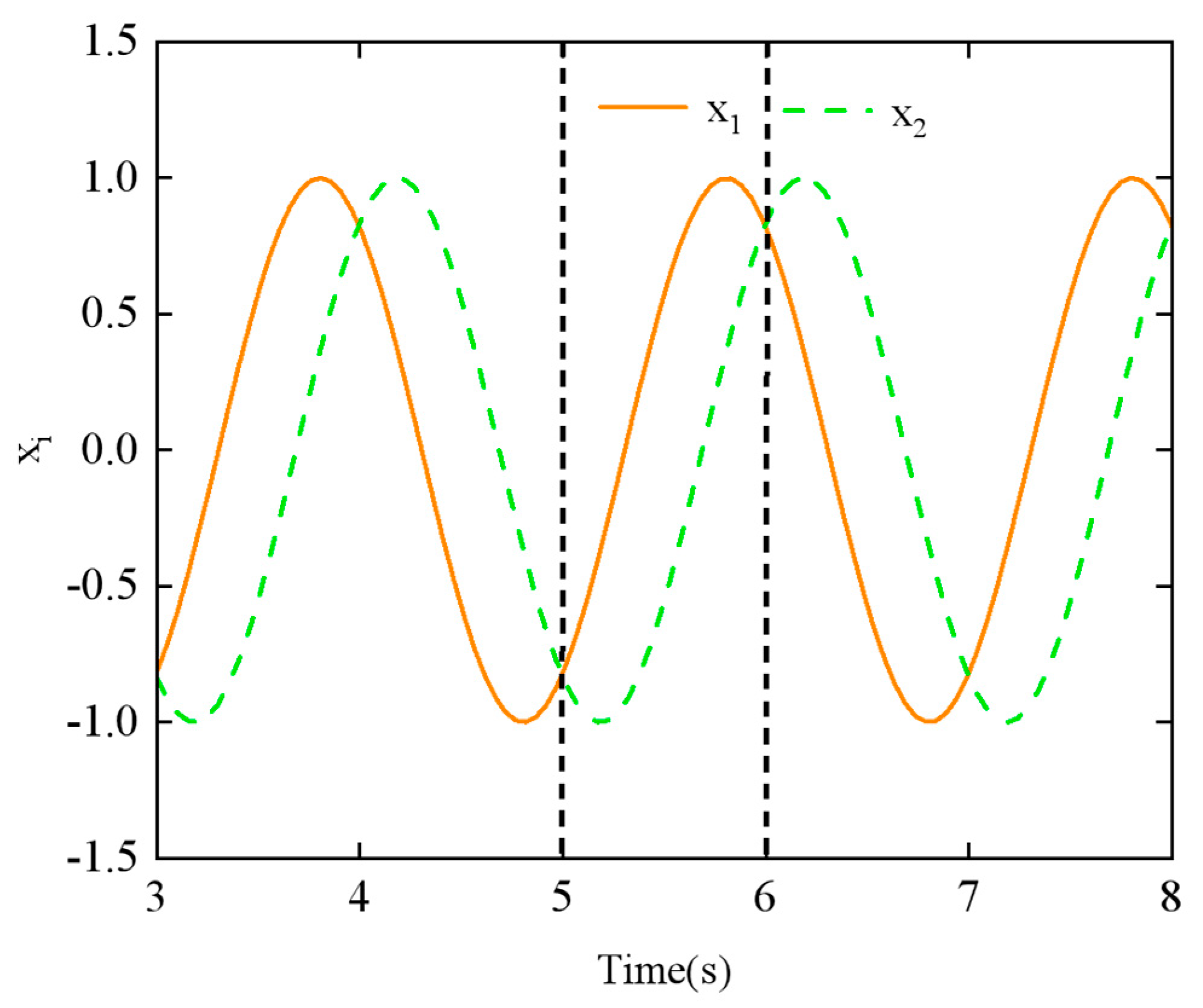
To validate the effect of geometric smoothness, simulation experiments were conducted to evaluate the output signal of the linear smoothing switching algorithm applied to the CPG network. In this experiment, the phase difference of neighboring joints ϕij is used as the adjustment parameter. The initial and final phase differences were set to ϕ1 = π/4 and ϕ2 = π/2, respectively, with (n = 8) joints. The switching time, (t2 − t1), was set to 1 s.
The output signal of the CPG network using the linear smoothing switching algorithm is shown in
Figure 14. When compared to
Figure 11, it is evident that the smoothness of the output signal
xi over time is significantly improved during the transition period between (
t1 = 5 s) and (
t2 = 6 s).
5. Conclusions
This study presents a comprehensive approach to enhancing the performance of snake-like robots in complex exploration and rescue missions, with three key contributions:
(1) Bio-inspired Compliant Mechanism: A novel hybrid joint design combining compliant mechanisms and Mecanum wheels was developed. Supported by screw theory-based kinematics and Newton–Euler dynamics modeling, this design significantly improves terrain adaptability and mobility.
(2) Smooth Multimodal Gait Control: A dual-chain central pattern generator (CPG) network, integrated with linear smoothing algorithms, was proposed to enable seamless gait transitions. This approach addresses the signal discontinuity issues commonly encountered in conventional methods.
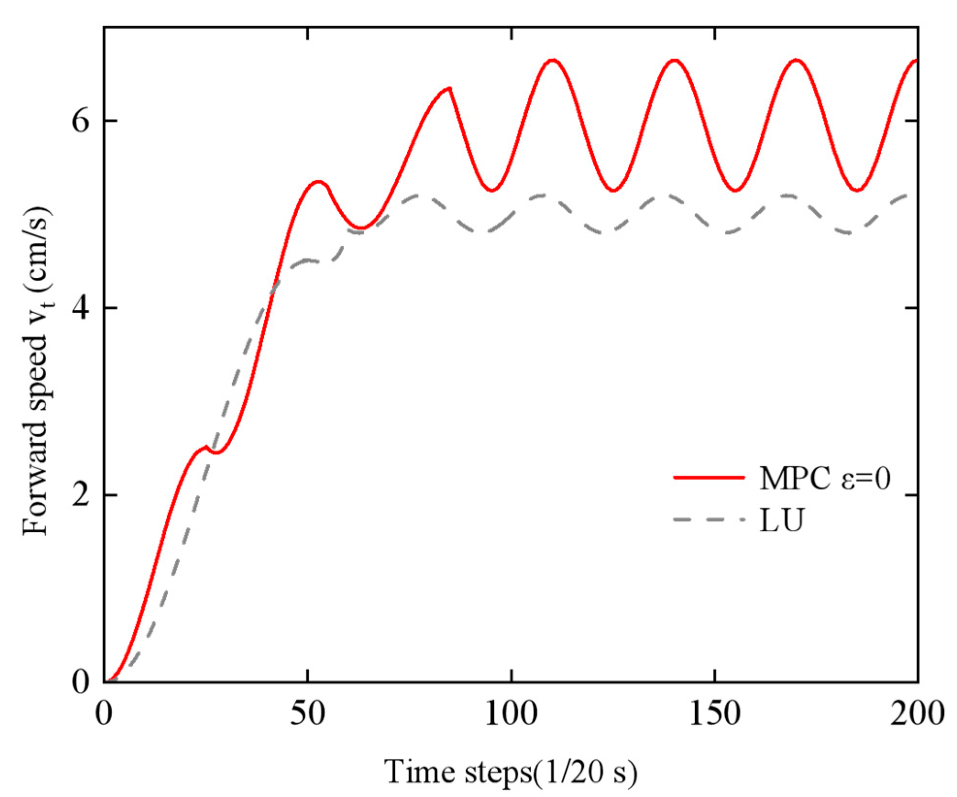
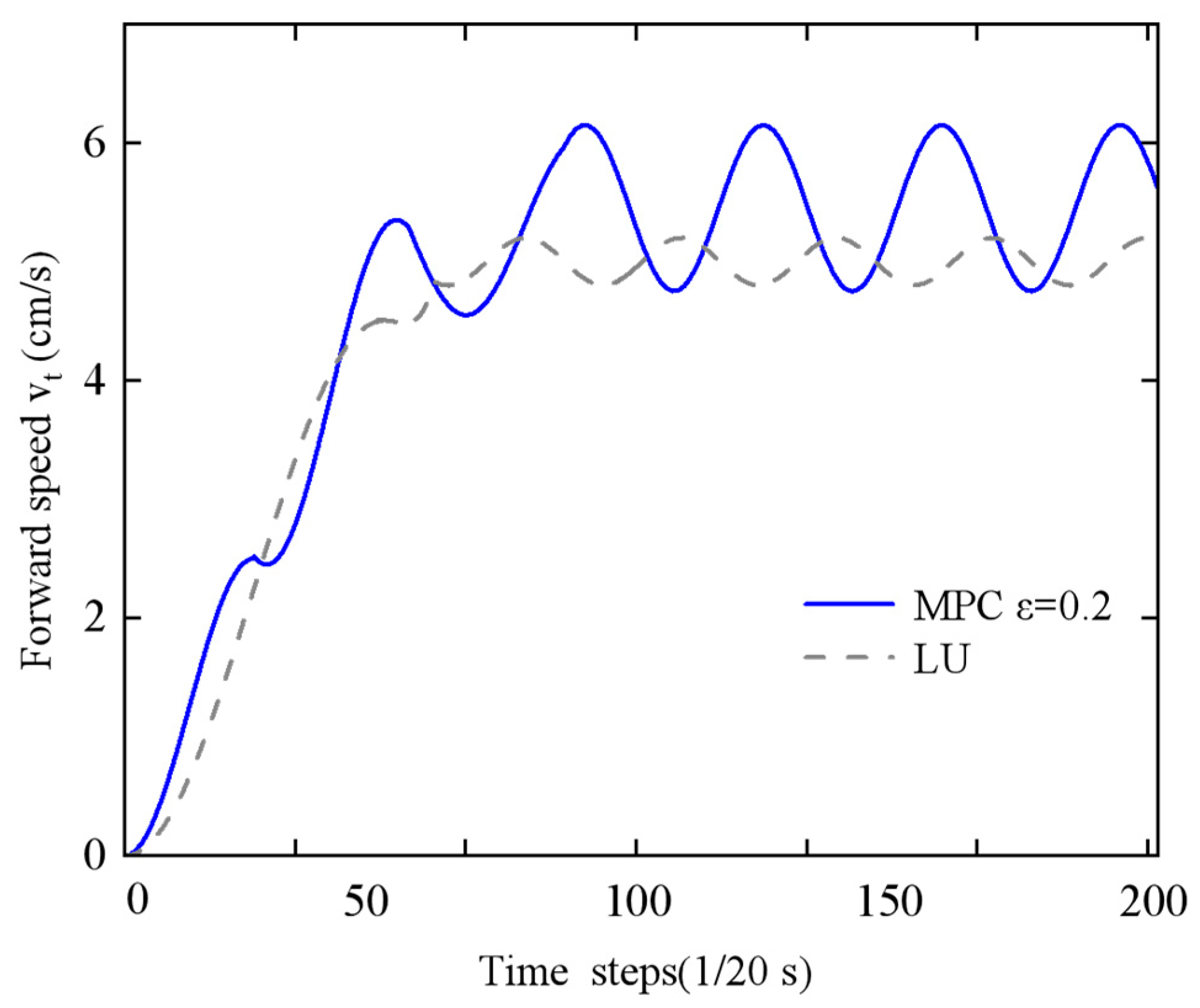
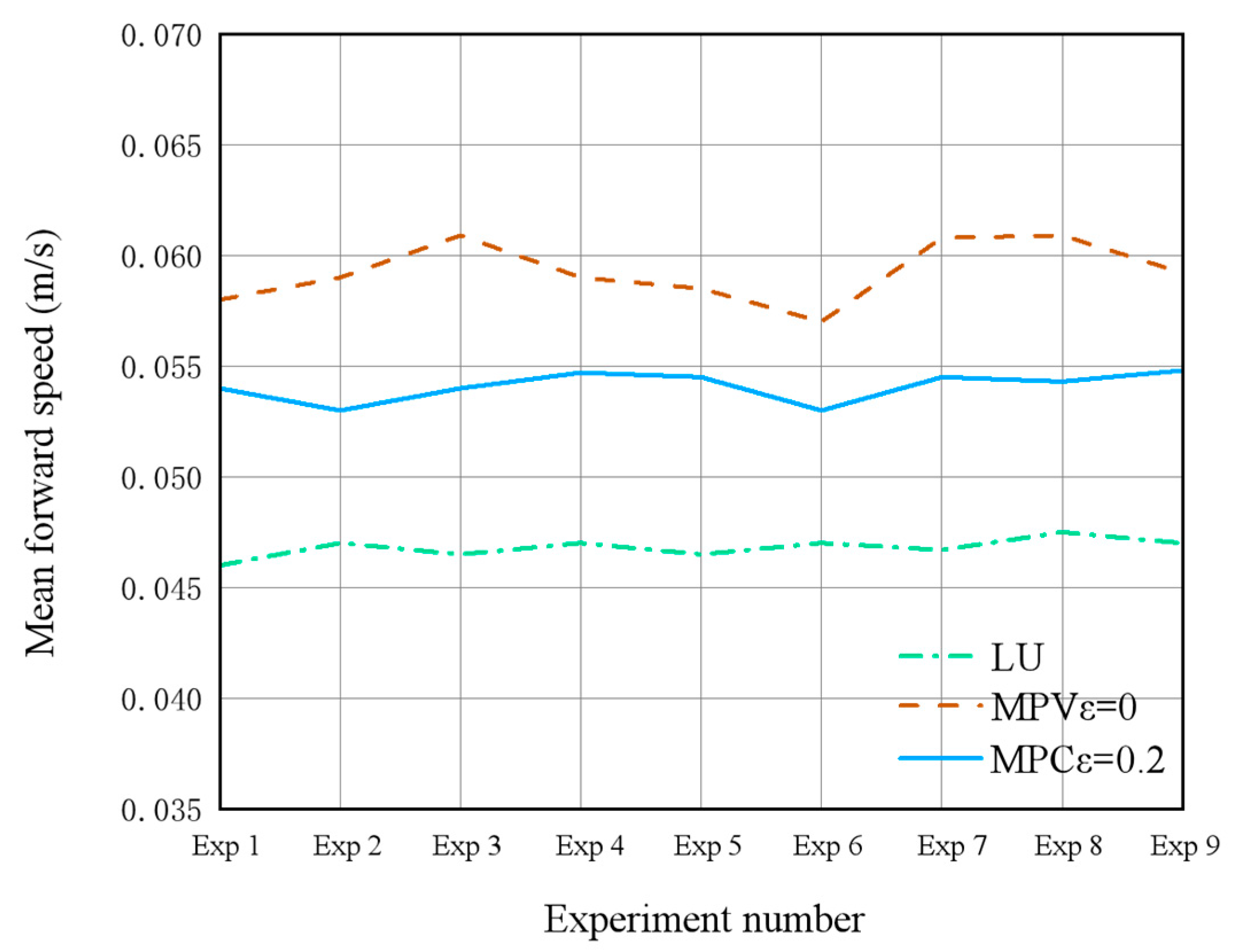
(3) Energy–Speed Co-optimization: An economic Model Predictive Control (MPC) framework was established to overcome the limitations of traditional single-objective optimization strategies. In simulations, this framework achieved a 7% reduction in energy consumption (0.1952 J vs. 0.2107 J) and an 18% increase in average forward speed (0.0563 m/s vs. 0.0478 m/s) compared to traditional controllers. Prototype experiments demonstrated a 12.9% speed improvement and 7.3% energy reduction, validating the approach’s practical efficacy.
Collectively, these innovations—spanning bio-inspired compliant joints, adaptive gait control, and energy–speed co-optimization—significantly advance the operational efficacy and deployment readiness of snake-like robots in unstructured environments. However, the precise energy-saving mechanisms underlying this synergy remain partially unresolved. Specifically, the distinct roles of mechanical compliance (e.g., anisotropic friction via Mecanum wheels) versus control intelligence (e.g., MPC-driven trajectory optimization) in enhancing energy conversion efficiency require deeper mechanistic validation. While the Cost of Transport (CoT) metric (
Table 2 and
Table 3) indirectly supports improved efficiency, direct quantification through power flow analysis—such as correlating motor input power with net forward propulsion—is absent.
To bridge these gaps, future work will prioritize the following:
(1) Decoupling mechanical and control contributions via ablation studies (e.g., rigid-joint variants) to isolate MPC-driven energy savings;
(2) Developing a dynamic power model that quantifies energy transfer pathways by integrating bionic mechanics (e.g., spinal elasticity) with adaptive control (e.g., phase-smoothing);
(3) Validating synergistic principles through multiphysics co-simulations (e.g., ADAMS-CoppeliaSim) to uncover governing laws of structure–control co-optimization.
These initiatives will establish a foundational theory for energy-aware bio-inspired robotics, enabling the robust design of high-efficiency systems in complex terrains.


 ,
, 
