

Water Impact on Superhydrophobic Surface: One Hydrophilic Spot Morphing and Controlling Droplet Rebounce


Abstract
1. Introduction
2. Materials and Methods
2.1. Materials
2.2. Surfaces Preparation
2.3. Experimental Setup
3. Results and Discussion
 , one end of this pattern was imaged by SEM in Figure 2f) in Figure 2h, a centra assisted spread is promoted. The droplet impacted spreads fast along the pattern with the outward flow generating cups at the ends. The contact line on the hydrophilic pattern gets pinned during recoil; on the superhydrophobic region, the contact line continues to recede until the outward flow impacts the inward flow, leaving a hydrophilic region defined water pattern on the surface with the rest of droplet take-off (see Video S2). Another example in Figure 2i shows a superhydrophobic surfaces containing three hydrophilic circles (radius = 2 mm) (⸫, one circle of this pattern was imaged by SEM in Figure 2g). The droplet impact on the centra of three hydrophilic circles. The droplet spreads and recedes, but the contact line on the hydrophilic circles gets pinned during recoil, which tailors the water droplet into three drops after an impact (see Video S3).
4. Conclusions
Supplementary Materials
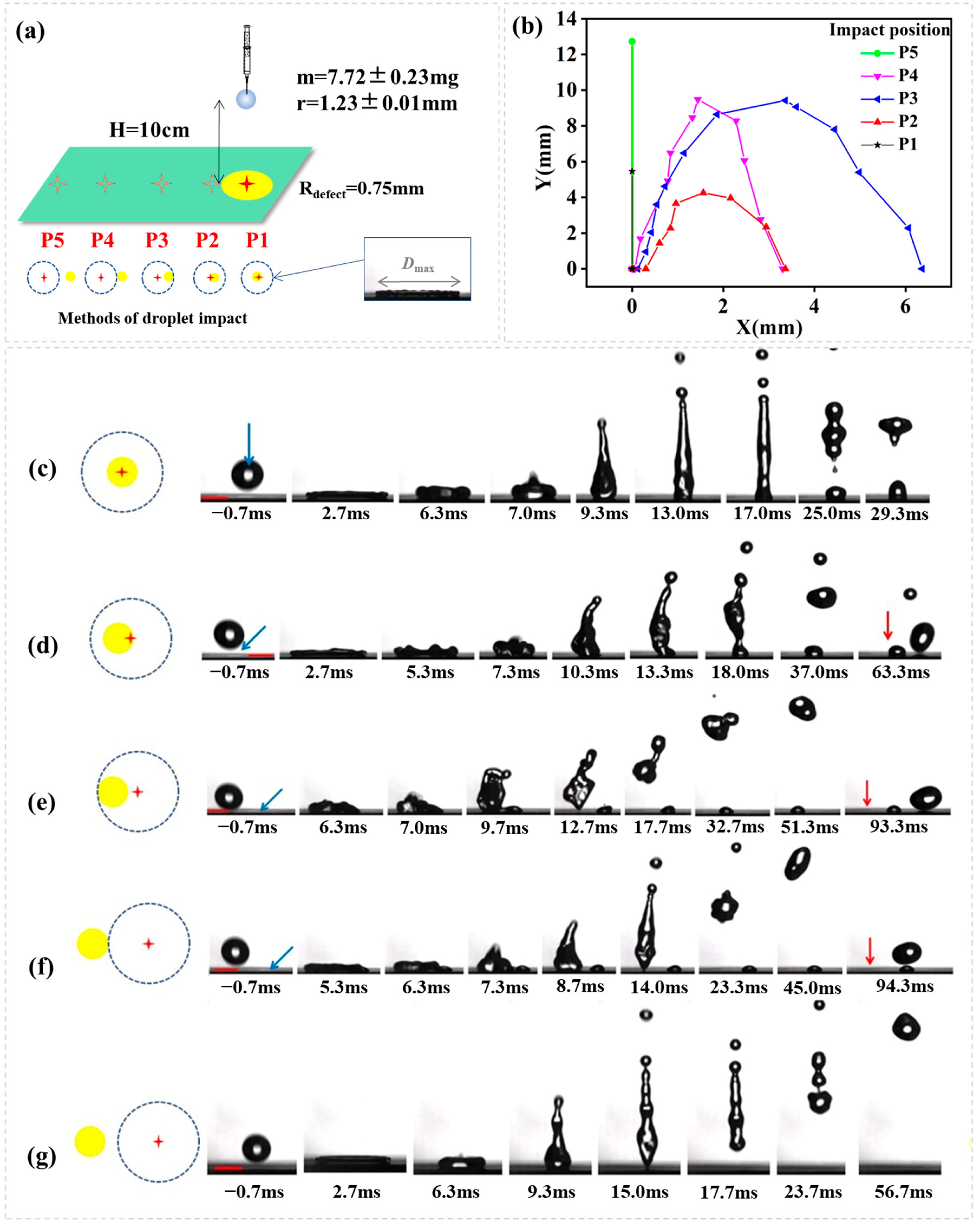
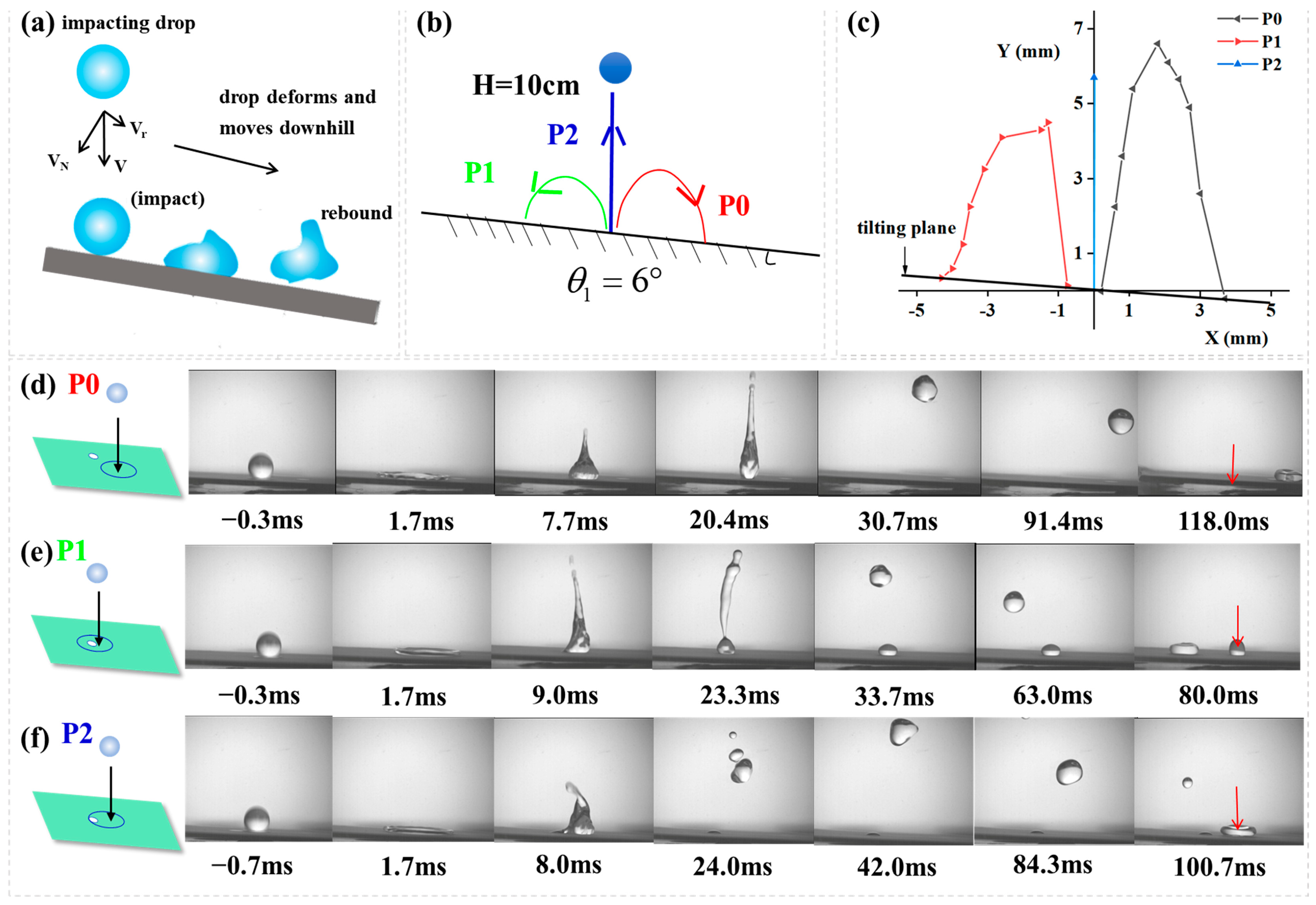
); Video S3: A water droplet dropped from a height of 5 cm to a superhydrophobic surfaces containing three hydrophilic circles (radius = 2 mm) (⸫); Video S4: The process of droplet impacting on P3; Video S5: The complete impacting process at P2 on inclined surface.Author Contributions
Funding
Institutional Review Board Statement
Informed Consent Statement
Data Availability Statement
Conflicts of Interest
References
- Liu, Z.; Luo, Y.; Chen, L.; Yang, Y.; Lyu, S.; Luo, Z. The Droplet Creeping-Sliding Dynamic Wetting Mechanism on Bionic Self-Cleaning Surfaces. Langmuir 2024, 40, 12602–12612. [Google Scholar] [CrossRef] [PubMed]
- Wang, X.; Wang, B.-B.; Deng, B.; Xu, Z.-M. Superior droplet bouncing, anti-icing/anti-frosting and self-cleaning performance of an outstanding superhydrophobic PTFE coating. Cold Reg. Sci. Technol. 2024, 224, 104229. [Google Scholar] [CrossRef]
- Ren, H.; Zhu, S.; Xiao, Y.; Li, C. Self-Propelled Nanodroplet Jumping Enhanced by Nanocone Arrays: Implications for Self-Cleaning and Anti-Icing Surfaces. ACS Appl. Nano Mater. 2022, 5, 810–817. [Google Scholar] [CrossRef]
- Xiang, H.; Yuan, Y.; Dai, X.; Zhu, T.; Zhao, Y.; Song, L.; Liao, R. A novel superhydrophobic Al conductor with excellent anti-icing performance and its mechanism. Surf. Interfaces 2024, 46, 104138. [Google Scholar] [CrossRef]
- Su, S.; Liang, J.; Li, X.; Xin, W.; Ye, X.; Xiao, J.; Xu, J.; Chen, L.; Yin, P. Hierarchical Artificial Compound Eyes with Wide Field-of-View and Antireflection Properties Prepared by Nanotip-Focused Electrohydrodynamic Jet Printing. ACS Appl. Mater. Interfaces 2021, 13, 60625–60635. [Google Scholar] [CrossRef] [PubMed]
- Ma, C.; Wang, L.; Xu, Z.; Tong, W.; Zheng, Q. Uniform and Persistent Jumping Detachment of Condensed Nanodroplets. Nano Lett. 2024, 24, 1439–1446. [Google Scholar] [CrossRef]
- Li, Y.; Qin, X.; Feng, Y.; Song, Y.; Yi, Z.; Zheng, H.; Zhou, P.; Wu, C.; Yang, S.; Wang, L.; et al. A droplet-based electricity generator incorporating Kelvin water dropper with ultrahigh instantaneous power density. Droplet 2024, 3, e91. [Google Scholar] [CrossRef]
- Xu, W.; Zheng, H.; Liu, Y.; Zhou, X.; Zhang, C.; Song, Y.; Deng, X.; Leung, M.; Yang, Z.; Xu, R.X.; et al. A droplet-based electricity generator with high instantaneous power density. Nature 2020, 578, 392–396. [Google Scholar] [CrossRef]
- Jiang, M.; Wang, Y.; Liu, F.; Du, H.; Li, Y.; Zhang, H.; To, S.; Wang, S.; Pan, C.; Yu, J.; et al. Inhibiting the Leidenfrost effect above 1,000 °C for sustained thermal cooling. Nature 2022, 601, 568–572. [Google Scholar] [CrossRef]
- Kumar, V.; Fu, Q.; Szeto, H.; Zhu, Y. Heat transfer during droplet impact on a cold superhydrophobic surface via interfacial thermal mapping. Droplet 2024, 3, e124. [Google Scholar] [CrossRef]
- Nan, L.; Lai, M.Y.A.; Tang, M.Y.H.; Chan, Y.K.; Poon, L.L.M.; Shum, H.C. Droplet-Based Microfluidics: On-Demand Droplet Collection for Capturing Single Cells (Small 9/2020). Small 2020, 16, 2070044. [Google Scholar] [CrossRef]
- Strutt, R.; Xiong, B.; Abegg, V.F.; Dittrich, P.S. Open microfluidics: Droplet microarrays as next generation multiwell plates for high throughput screening. Lab Chip 2024, 24, 1064–1075. [Google Scholar] [CrossRef] [PubMed]
- Richard, D.; Clanet, C.; Quéré, D. Contact time of a bouncing drop. Nature 2002, 417, 811. [Google Scholar] [CrossRef] [PubMed]
- Liu, Y.; Moevius, L.; Xu, X.; Qian, T.; Yeomans, J.M.; Wang, Z. Pancake bouncing on superhydrophobic surfaces. Nat. Phys. 2014, 10, 515–519. [Google Scholar] [CrossRef]
- Guo, C.; Zhao, D.; Sun, Y.; Wang, M.; Liu, Y. Droplet Impact on Anisotropic Superhydrophobic Surfaces. Langmuir 2018, 34, 3533–3540. [Google Scholar] [CrossRef]
- Bird, J.C.; Dhiman, R.; Kwon, H.-M.; Varanasi, K.K. Reducing the contact time of a bouncing drop. Nature 2013, 503, 385–388. [Google Scholar] [CrossRef]
- Gauthier, A.; Symon, S.; Clanet, C.; Quéré, D. Water impacting on superhydrophobic macrotextures. Nat. Commun. 2015, 6, 8001. [Google Scholar] [CrossRef]
- Weisensee, P.B.; Tian, J.; Miljkovic, N.; King, W.P. Water droplet impact on elastic superhydrophobic surfaces. Sci. Rep. 2016, 6, 30328. [Google Scholar] [CrossRef]
- Liu, Y.; Andrew, M.; Li, J.; Yeomans, J.M.; Wang, Z. Symmetry breaking in drop bouncing on curved surfaces. Nat. Commun. 2015, 6, 10034. [Google Scholar] [CrossRef]
- Shen, Y.; Liu, S.; Zhu, C.; Tao, J.; Chen, Z.; Tao, H.; Pan, L.; Wang, G.; Wang, T. Bouncing dynamics of impact droplets on the convex superhydrophobic surfaces. Appl. Phys. Lett. 2017, 110, 221601. [Google Scholar] [CrossRef]
- Zhang, R.; Hao, P.; He, F. Drop Impact on Oblique Superhydrophobic Surfaces with Two-Tier Roughness. Langmuir 2017, 33, 3556–3567. [Google Scholar] [CrossRef]
- Yun, S. Bouncing of an ellipsoidal drop on a superhydrophobic surface. Sci. Rep. 2017, 7, 17699. [Google Scholar] [CrossRef] [PubMed]
- Li, H.; Fang, W.; Li, Y.; Yang, Q.; Li, M.; Li, Q.; Feng, X.-Q.; Song, Y. Spontaneous droplets gyrating via asymmetric self-splitting on heterogeneous surfaces. Nat. Commun. 2019, 10, 950. [Google Scholar] [CrossRef]
- Gu, S.; Ge, H.; Wei, H.; Sun, Y.; Zhang, T.; Wang, H.; Wu, L.; Fan, X. Study on the regulation of droplet motion behavior on superhydrophobic surfaces. Chem. Eng. J. 2024, 498, 155282. [Google Scholar] [CrossRef]
- Zhang, L.; Wu, J.; Lu, Y.; Yu, Y. Droplets impact on sparse microgrooved non-wetting surfaces. Sci. Rep. 2025, 15, 2918. [Google Scholar] [CrossRef] [PubMed]
- Wu, J.; Zhang, L.; Lu, Y.; Yu, Y. Droplet impinging on sparse micropillar-arrayed non-wetting surfaces. Phys. Fluids 2024, 36, 097123. [Google Scholar] [CrossRef]
- Lu, Y.; Shen, Y.; Tao, J.; Wu, Z.; Chen, H.; Jia, Z.; Xu, Y.; Xie, X. Droplet Directional Movement on the Homogeneously Structured Superhydrophobic Surface with the Gradient Non-Wettability. Langmuir 2020, 36, 880–888. [Google Scholar] [CrossRef]
- Cao, C.-L.; Xu, J.-L.; Ye, W.-L. Self-propulsion droplet induced via periodic explosive boiling. Acta Phys. Sin. 2021, 70, 244703. [Google Scholar] [CrossRef]
- Guo, Q.; Zhan, F.; Li, M.; Shi, Y.; Wen, J.; Zhang, Q.; Zhou, N.; Wang, L.; Mao, H. Directional propulsion of transition boiling droplets on high-temperature surfaces induced by tilted nanoforests with asymmetric wettability. Surf. Interfaces 2025, 56, 105623. [Google Scholar] [CrossRef]
- Clanet, C.; BÉGuin, C.; Richard, D.; QuÉRÉ, D. Maximal deformation of an impacting drop. J. Fluid Mech. 2004, 517, 199–208. [Google Scholar] [CrossRef]
- Dong, T.; McCarthy, T.J. Superhydrophobic, Low-Hysteresis Patterning Chemistry for Water-Drop Manipulation. ACS Appl. Mater. Interfaces 2017, 9, 41126–41130. [Google Scholar] [CrossRef] [PubMed]
- Cheng, D.F.; McCarthy, T.J. Using the fact that wetting is contact line dependent. Langmuir 2011, 27, 3693–3697. [Google Scholar] [CrossRef] [PubMed]
- Antonini, C.; Villa, F.; Bernagozzi, I.; Amirfazli, A.; Marengo, M. Drop Rebound after Impact: The Role of the Receding Contact Angle. Langmuir 2013, 29, 16045–16050. [Google Scholar] [CrossRef]
- Guan, Y.; Fu, J.; Wu, S.; Yu, C.; Chen, X.; Zhou, C. The dynamical behaviors of water drop impacting and bouncing on an inclined hydrophobic surface. Colloids Surf. A 2021, 627, 127087. [Google Scholar] [CrossRef]
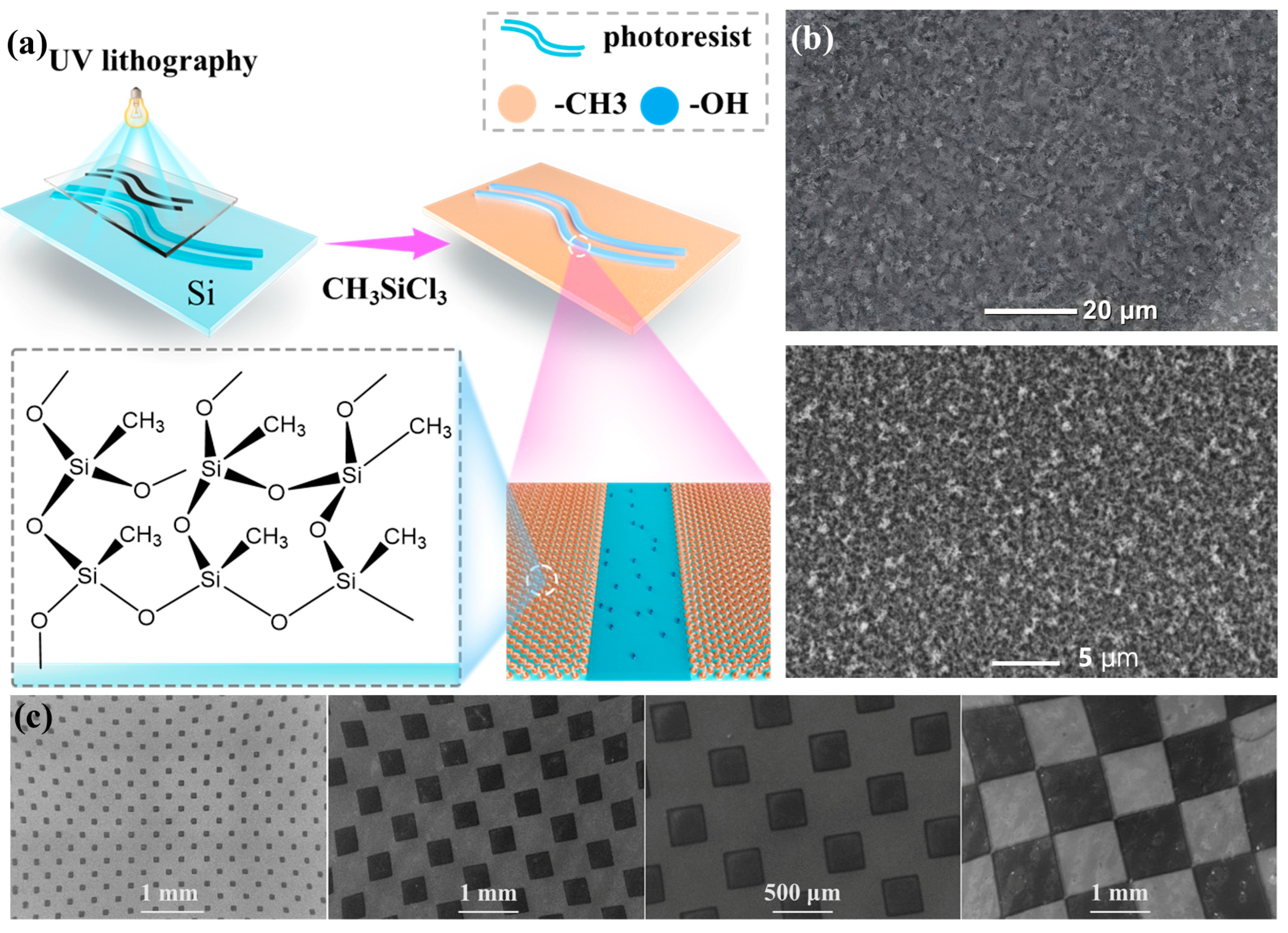 ) and one end of this pattern’s SEM image; (g) superhydrophobic surfaces containing three hydrophilic circles (radius = 2 mm) (⸫) and one circle of this pattern’s SEM image; Photographs of a water droplet dropped from a height of 5 cm to superhydrophobic surface containing different hydrophilic patterns. (h) superhydrophobic surface patterned with two hydrophilic triangles connecting by a line (); (i) superhydrophobic surfaces containing three hydrophilic circles (⸫).
) and one end of this pattern’s SEM image; (g) superhydrophobic surfaces containing three hydrophilic circles (radius = 2 mm) (⸫) and one circle of this pattern’s SEM image; Photographs of a water droplet dropped from a height of 5 cm to superhydrophobic surface containing different hydrophilic patterns. (h) superhydrophobic surface patterned with two hydrophilic triangles connecting by a line (); (i) superhydrophobic surfaces containing three hydrophilic circles (⸫).
) and one end of this pattern’s SEM image; (g) superhydrophobic surfaces containing three hydrophilic circles (radius = 2 mm) (⸫) and one circle of this pattern’s SEM image; Photographs of a water droplet dropped from a height of 5 cm to superhydrophobic surface containing different hydrophilic patterns. (h) superhydrophobic surface patterned with two hydrophilic triangles connecting by a line (); (i) superhydrophobic surfaces containing three hydrophilic circles (⸫).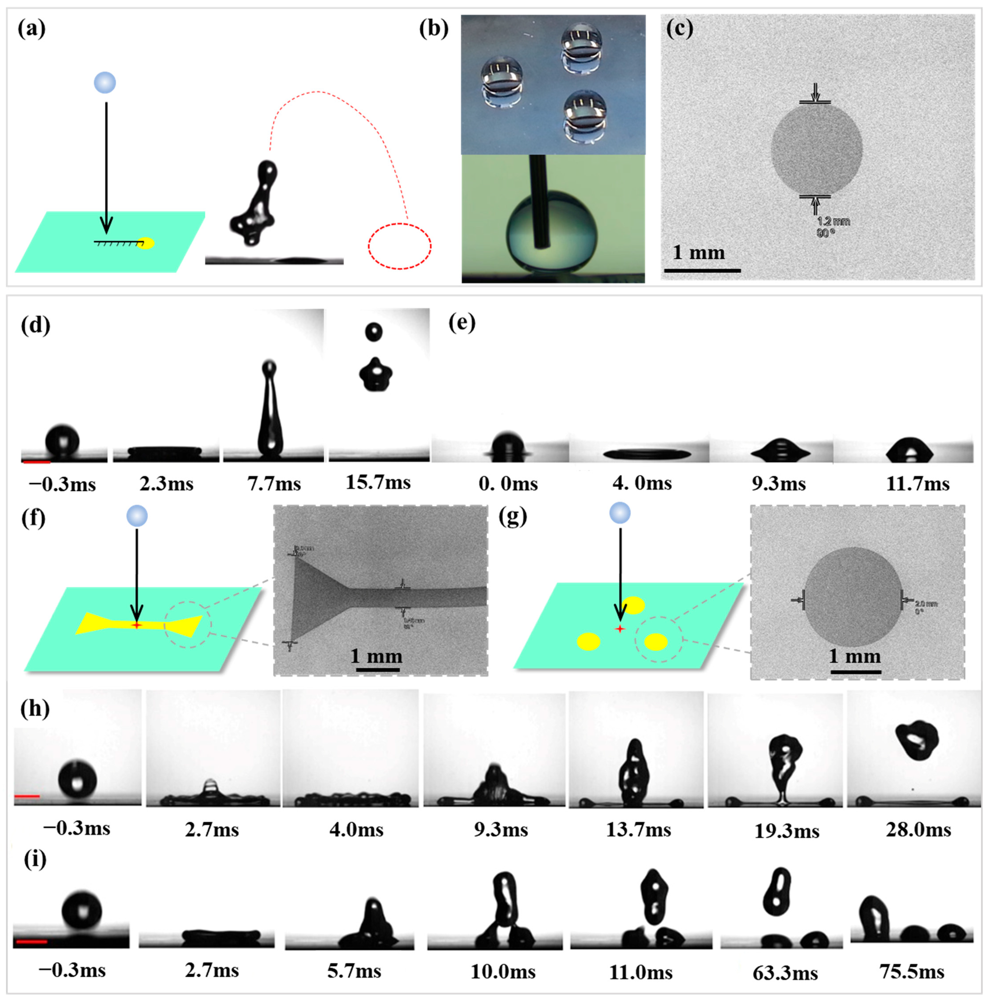


Disclaimer/Publisher’s Note: The statements, opinions and data contained in all publications are solely those of the individual author(s) and contributor(s) and not of MDPI and/or the editor(s). MDPI and/or the editor(s) disclaim responsibility for any injury to people or property resulting from any ideas, methods, instructions or products referred to in the content. |
© 2025 by the authors. Licensee MDPI, Basel, Switzerland. This article is an open access article distributed under the terms and conditions of the Creative Commons Attribution (CC BY) license (https://creativecommons.org/licenses/by/4.0/).
Share and Cite
Guo, J.; Zhao, H.; Lou, C.-W.; Dong, T. Water Impact on Superhydrophobic Surface: One Hydrophilic Spot Morphing and Controlling Droplet Rebounce. Biomimetics 2025, 10, 319. https://doi.org/10.3390/biomimetics10050319
Guo J, Zhao H, Lou C-W, Dong T. Water Impact on Superhydrophobic Surface: One Hydrophilic Spot Morphing and Controlling Droplet Rebounce. Biomimetics. 2025; 10(5):319. https://doi.org/10.3390/biomimetics10050319
Chicago/Turabian StyleGuo, Jiali, Haoran Zhao, Ching-Wen Lou, and Ting Dong. 2025. "Water Impact on Superhydrophobic Surface: One Hydrophilic Spot Morphing and Controlling Droplet Rebounce" Biomimetics 10, no. 5: 319. https://doi.org/10.3390/biomimetics10050319
APA StyleGuo, J., Zhao, H., Lou, C.-W., & Dong, T. (2025). Water Impact on Superhydrophobic Surface: One Hydrophilic Spot Morphing and Controlling Droplet Rebounce. Biomimetics, 10(5), 319. https://doi.org/10.3390/biomimetics10050319