Article

Occupational Risk Assessment During Carbon Fibre Sizing Using Engineered Nanomaterials

by
Spyridon Damilos
1,
Dionisis Semitekolos
2,
Stratos Saliakas
1,
Adamantia Kostapanou
1,
Costas Charitidis
2 and
Elias P. Koumoulos
1,*
1
Innovation in Research & Engineering Solutions (IRES), 1000 Brussels, Belgium
2
Research Lab of Advanced, Composite, Nano-Materials and Nanotechnology (R-NanoLab), School of Chemical Engineering, National Technical University of Athens, 15773 Athens, Greece
*
Author to whom correspondence should be addressed.
Safety 2025, 11(1), 11; https://doi.org/10.3390/safety11010011
Submission received: 30 October 2024 / Revised: 13 January 2025 / Accepted: 16 January 2025 / Published: 21 January 2025
(This article belongs to the Special Issue Safety and Risk Management in Process Industries)

Abstract

Carbon fibre-reinforced polymers (CFRPs) are a lightweight alternative solution for various applications due to their mechanical and structural properties. However, debonding at the fibre–matrix interface is an important failure mechanism in composite materials. Proposed solutions include using nano-scale reinforcements to strengthen and toughen structural composites. This study covers a comprehensive approach for evaluating occupational hazards during the sizing of 6k carbon fibres using multi-walled functionalized carbon nanotubes (MWCNTs) and few-layer graphene (FLG) at a pilot scale. Material hazard and exposure banding showed elevated risks of exposure to nanomaterials during the sizing process, while a ‘what-if’ process hazard analysis allowed for the evaluation of hazard control options against the hypothetical process failure scenarios of human error and utilities malfunctioning. On-site measurements of airborne particles highlighted that using MWCNTs or FLG as a sizing agent had negligible effects on the overall exposure potential, and higher micro-size particle concentrations were observed at the beginning of the process, while particle size distribution showcased high concentrations of particles below 50 nm. This analysis provides a thorough investigation of the risks and potential exposure to airborne hazardous substances during CF sizing while providing insights for the effective implementation of a safe-by-design strategy for designing targeted hazard control systems.

Graphical Abstract

1. Introduction

Carbon fibre-reinforced polymers (CFRPs) are being used in many different industries, such as the automotive [1], aerospace [2], construction [3], defence [4] and energy (such as wind and tidal turbine blades) industries [5,6,7], due to their unique structural and mechanical properties and their strength-to-weight ratio [8,9]. Current global market estimations signify that the carbon fibre market size is valued at $3.59 billion (2024) and is projected to grow to $7.05 billion by 2032 at an annual compound growth rate (CAGR) of 8.8% [10]. The properties and subsequent application of the CFRPs depend on various parameters, such as the polymer matrix, the chemical composition of the carbon fibres (CFs), their surface morphology and orientation, and the interfacial bonding between the CFs and the polymer resins [11,12].
The compatibility between the CF and polymer matrix is considered one of the most important parameters affecting the properties and applications of the CFRP. Significant research has been undertaken on the development of epoxy resins acting as polymer matrices offering good processability, low shrinkage and excellent mechanical and chemical properties [12]. However, debonding at the fibre–matrix interface is an important failure mechanism in composite material [13]. To enhance the interfacial strength between the CFs and the polymer matrix, several approaches have been studied to modify the CF surface, such as increasing the roughness of the CFs, using chemical functional groups and sizing via the use of thin coating material on the CFs [9,11,12]. Sizing is a widely used technique to ensure adequate bonding and cohesion between the CF and the polymer resin, improving the structural integrity of the CFRP, minimising the presence of voids and defects and enhancing the stress transferring from the polymer matrix to the embedded CF [12,14,15]. Common sizing agents include the use of low-molecular-weight polymers, antistatic agents and emulsifiers [11,16,17], while recent research has focused on the use of bio-based alternative compounds [17], degradable epoxy resin-based molecules [15] and engineered nanomaterials (ENMs) [18]. Due to their size and their mechanical properties, nanomaterials can be well dispersed on the CF surface, strengthening the polymer–fibre interface, thus enhancing the properties of the CFRPs. Several types of nanomaterials have been researched and used, such as inorganic nanomaterials [19], carbon nanotubes (CNTs) [20] and modified EMNs [21], to augment their properties.
Literature studies have analysed health and safety concerns in carbon fibre processing, as well as the potential exposure to potent ENMs in manufacturing procedures. The main safety aspect includes exposure to vapours from the polymer matrix, particulate matter, volatile organic compounds (VOCs) from the used additives and chemicals (e.g., hardeners and curing agents) and fibrous airborne composite particles during CFRP processing (e.g., cutting and milling) [22]. Kehren et al. discussed the potential release of respirable fibrous dust from the processing of carbon fibres [23]. Tölle et al. analysed the released dust from processing and recycling of the CFRPs, showcasing the potential exposure of workers to respirable fibres during shredding of the composite polymers [24]. Their analysis highlighted the release of fibre fragments which have different cytotoxic effects on human health in comparison with the granular dust, due to their fibrous nature, and this should be taken into consideration during process design.
Particulate matter can be divided into three major categories according to its size and penetration in the respiratory tract. Particles can be categorised based on their aerodynamic equivalent diameter into inhalable particles < 10 μm in diameter (PM10) and respirable fractions of particles < 4 μm (PM4). These types of micro-size particles can enter the head airways and can be removed either via exhalation or by passing through the tracheobronchial region [25]. Their toxicological characteristics depend strongly on their physicochemical properties (size, shape, chemical composition, etc.) [26]. Particles that are deposited in the respiratory tract can also be cleared to the gastrointestinal tract via the pharynx or to the regional lymph nodes via lymphatic channels. Ultrafine particles (UFPs, particles < 100 nm in diameter) have a similar size range as incidental and engineered nanomaterials and are considered to pose a higher risk to human health, as they can penetrate the respiratory tract and be deposited in the alveolar region [27]. Deposition in the alveoli, which are some of the most sensitive parts, can lead to adverse health effects if the particles are not cleared through the immune system [25]. A small fraction of nanoparticles deposited in the alveolar region may be cleared into the bloodstream by absorption; however, this could lead to translocation to other organs (e.g., pancreas, liver, etc.).
ENMs present greater occupational risks than their bulk alternatives, due to their small size and subsequently large surface area, as they can penetrate the cellular membrane, causing oxidative stress and leading to inflammation and cell apoptosis [28,29]. The parameters affecting nanomaterial toxicity are, similarly to UFPs, the particle size and morphology, as well as the surface chemistry and surface charge [28]. Several literature studies have investigated the potency and cytotoxicity of ENMs, the recommended exposure limits and the health and safety strategies to mitigate any related risks [30,31,32]. ENMs can be divided into several categories based on their chemical structure, such as carbonaceous or carbo-based nanomaterials (e.g., graphene, CNTs, nanofibers and fullerenes), nano-metal oxides (e.g., titanium oxide, silver oxide and zinc oxide) and metal nanoparticles (e.g., silver, gold and nickel), as well as other categories derived from polymeric materials (e.g., super absorbent polymers) and hybrid nanomaterials (e.g., core–shell nanoparticles), etc. [29,33]. Due to their small size (<100 nm), exposure to ENMs can take place via inhalation, skin uptake and ingestion, followed by potential translocation of the toxic components to other organs without being able to be removed from the body [28]. Despite their significant properties, the similarities in structure between CNTs and asbestos highlight the potential occupational health risks leading to pulmonary issues and fibrosis with carcinogenic effects [34,35]. Additionally, upon release during thermal or mechanical processing, short carbon fibres and CNTs—which exhibit fibrous structures of few micrometres (e.g., 5–10 μm in length and less than 100 nm in diameter)—could penetrate the respiratory tract in certain alignments, causing adverse health effects, similar to asbestos, such as phagocytosis, leading to oxidative stress and inflammation [8]. Additionally, despite the advantages of graphene in medical applications, graphene-family particles (such as graphene oxide (GO) and reduced graphene oxide (rGO)) have been shown to pose a serious threat to the respiratory and gastrointestinal tract, while fullerenes present a significantly lower toxicological potential [35,36].
Upon reviewing the toxicological and epidemiological evidence, there is a need for a systematic and comprehensive approach to the evaluation of exposure to UFP and ENMs in the workplace [30]. On-site monitoring by low-cost sensors lacks accuracy as nanomaterials have low mass concentrations [37], while nanomaterial potency is indirectly proportional to their size. At the same time, a measuring strategy and on-site assessment would provide the necessary screening, while emerging manufacturing plants could incorporate safe-by-design approaches, such as hazard and potential exposure evaluation, toxicological testing, hot-spot analyses, installation of adequate controls, etc., to ensure material and process safety in the early stages of development and prevent occupational and environmental risks [32,38,39].
In this study, a comprehensive risk evaluation is presented for hazards during the sizing of CFs using a pilot-scale fibre sizing line [21]. A thorough investigation of the potential risks to airborne (nano)particles is conducted via a tiered approach analysing the potency of the used materials and the exposure assessment through on-site measurements, along with a structured ‘what-if’ process hazard analysis elaborating on the consequences and potential failures that could occur and pose a risk to the operator’s safety.

2. Materials and Methods

2.1. Materials

In the experimental series, 6000 (6k) filaments per tow carbon fibres (Torayca, Toray CMA Inc., Tacoma, WA, USA) were used. The sizing solution consisted of an epoxy sizing agent (Hydrosize HP2-06, Michelman Inc., Cincinnati, OH, USA), using Triton X100 as a surfactant (Sigma Aldrich, Merck KGaA, Darmstadt, Germany) and two types of nanomaterials in the sizing solution, multi-walled carbon nanotubes (MWCNTs) and few-layer graphene (FLG) (Haydale Graphene Industries PLC, Ammanford, UK). Both nanomaterial types were N2-plasma-functionalised due to their significant enhancements in interfacial shear properties [21]. A 1 L sizing solution was prepared (with either the MWCNTs or the FLG) on the same day of the sizing process in an enclosed environment at room temperature by mixing all components using a mechanical agitator. The total nanomaterial content in the sizing bath was 0.1% wt. Τhe evaluation of different sizing solution parameters (solid content/nanomaterial type) on the carbon fibres’ surface was studied using an FEI Quanta 650 FEG (FEI, Hillsboro, OR, USA) scanning electron microscope (SEM), in magnifications up to ×10,000.

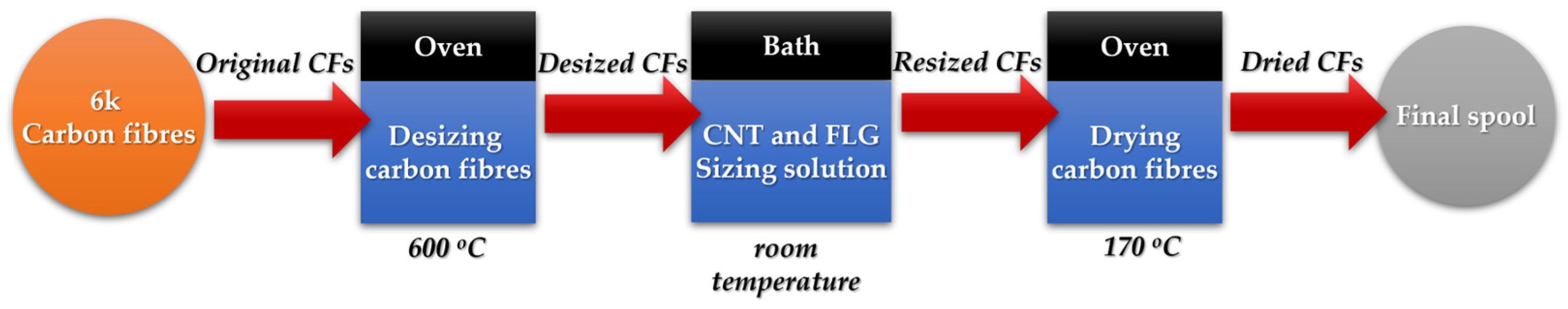
2.2. Carbon Fibre Sizing Pilot Line

A pilot-scale fibre sizing line was used for the sizing of the carbon fibres using carbon-based nanomaterials as additives in the sizing solution [21]. In the pilot line, a feed roller was pulling the carbon fibres from the let-off creel at a constant speed of 0.2 m/min, allowing the CFs to be submerged in the sizing solutions and in the desizing and drying units. During the sizing process, the carbon fibres initially passed through an oven for desizing at 600 °C, removing the unnecessary coating of the commercial CFs. Then, the uncoated CFs were immediately immersed in the appropriate aqueous nanomaterial (CNTs or FLG) at room temperature, using a series of rollers to guide the fibres through the sizing solution while squeeze rollers removed the excess solution from the CF surface. Finally, the resized carbon fibres passed through a second oven (at 170 °C) for drying to evaporate the remaining solvent and solidify the CF coating, before winding in the spool (Figure 1). The selected process parameters had previously shown maximum productivity during successful removal of the pre-existing sizing from the surface of the commercial CFs and sufficient sizing with the ENMs [21]. Additionally, a comparative study was performed where the uncoated CFs (after the desizing oven) did not pass through a sizing solution (bath) but entered the drying oven directly, thus allowing the evaluation and the role of the nanoenabled sizing solution on the potential exposure to airborne nanomaterials.

2.3. Information Gathering and Hazard Analysis

An initial (Tier 1) risk assessment of the CF sizing process was performed based on the information requirements described in EN 17058:2018 [40]. For this assessment, information was documented regarding the workplace, workplace activities (main and adjacent) and nano-objects, and their aggregate and agglomerate (NOAA) characteristics. Documentation of materials was expanded beyond NOAAs for the assessment to provide a holistic understanding of the health risks associated with the process. The collected material information was evaluated following the hazard banding methodology presented in ISO 12901-2:2014 [41]. The classification was performed based on the Global Harmonised System (GHS) hazard statements from materials safety data sheets (SDSs), certificates of analysis and the European Chemicals Agency’s Classification and Labelling (ECHA C&L) inventory [42]. Hazard bands (HBs) range from A—“No significant risk to health”—to E—“Severe hazard”. Exposure potential to NOAAs was also evaluated according to the exposure banding approach described in the same standard. ISO 12901-2:2014 presents specific criteria for the characterisation of exposure potential depending on the type of process and whether the NOAAs are handled in powder form, suspended in a liquid or embedded in a solid matrix. Exposure bands (EBs) range from 1—“Lowest”—to 4—“Highest” [41].

2.4. ‘What-If’ Process Hazard Analysis

A ‘what-if’ analysis was undertaken, in addition to the information gathering and material hazard evaluation, to investigate the safety aspects during the operation of the pilot sizing setup and associate the potential failures during the operation with their effects on the sizing of the CFs and the release of airborne (nano)particles. ‘What-if’ hazard analysis follows a loosely structured methodology performed by a team of experts and experienced professionals for the qualitative evaluation of the process risks through a series of hypothetical questions and scenarios [43,44]. Through the ‘what-if’ analysis, the broader safety aspects of the system under evaluation are analysed, while the team highlights the potential hazard scenarios and then addresses their causes, consequences and existing controls and recommends additional hazard control options where needed [44]. In our analysis, a cross-functional team was assembled comprising two experienced safety professionals and one trained operator of the CF sizing pilot line who was also involved in the design and construction of the process line. A spreadsheet was created and included information on (i) causes, (ii) consequences, (iii) controls and (iv) recommendations [44].

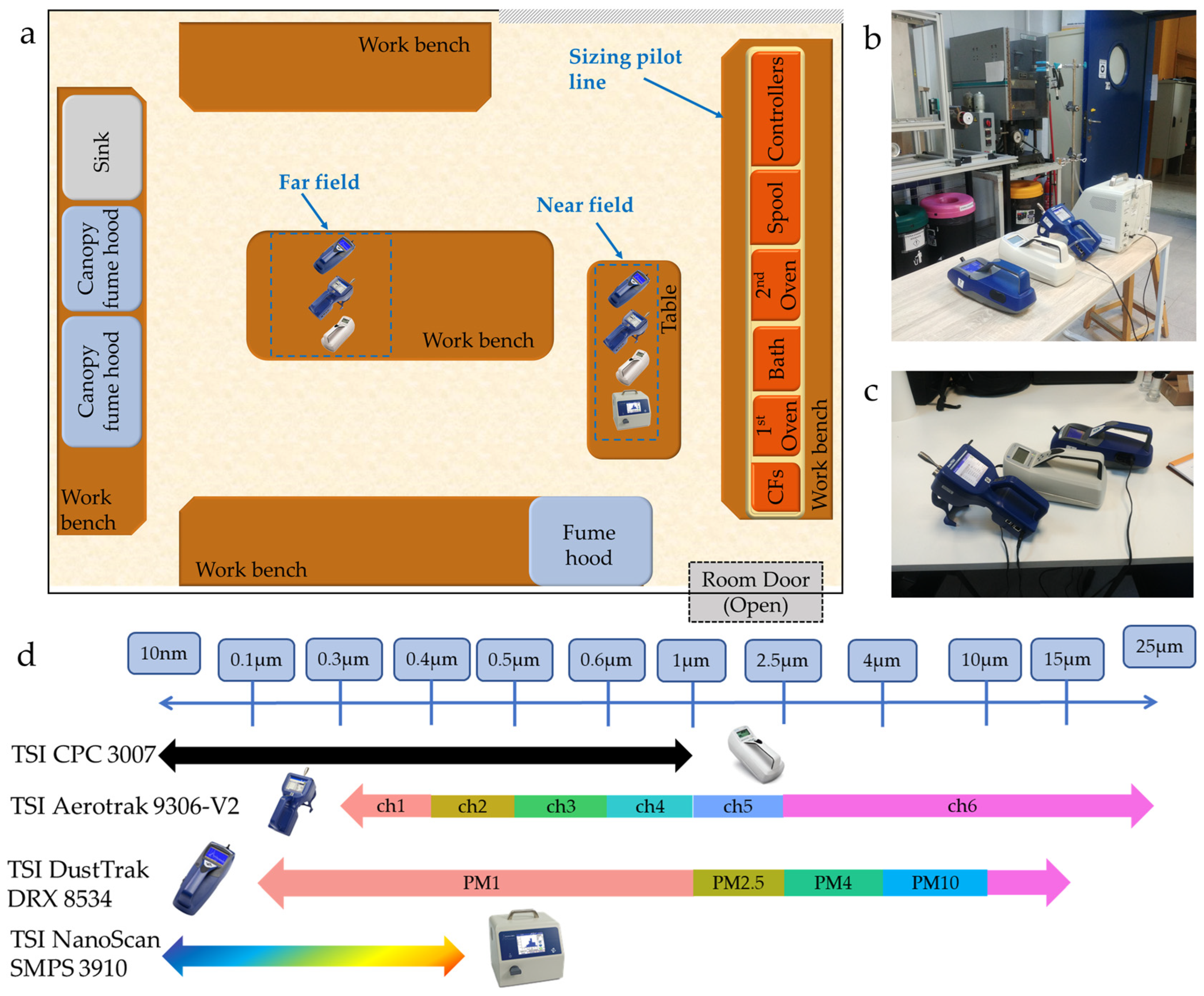
2.5. Occupational Exposure Assessment

Following the outcomes of the initial risk assessment and material hazard evaluation, analysis included an on-site exposure assessment; a wide inventory of instruments were used to monitor the potential operators’ exposure to airborne particles from 10 nm to 25 μm during the operation of the CF sizing process. Measuring equipment included condensation particle counters (CPCs) (CPC3007), optical particle counters (OPCs) (Aerotrak 9306-V2) and aerosol mass-based monitors (DustTrak DRX 8534) from TSI Inc. (Shoreview, MN, USA) positioned near (near-field: at ~1 m) and far from the sizing pilot line (far-field: at ~3.7 m). Aerotrak 9306-V2 allows for the measurement of particle concentration in six adjustable ranges from 0.3 μm to 10 μm, while DustTrak DRX 8534 provides a four-channel mass-based real-time aerosol reading of surrounding air from 0.1 μm to 15 μm. Additionally, a NanoScan SMPS 3910 (TSI Inc., Shoreview, MN, USA) was positioned in the near-field measurements for the evaluation of the particle size distribution of the emitted nano-size and sub-micron particles during the carbon fibre sizing process, providing the particle size distribution through 13 channels from 10 nm to 420 nm. In the measurement protocol, the data collection frequency was set at 1 s, while the different data log intervals were selected according to the instruments’ specifications to monitor concentration variations over time, as follows: 1 s for the CPCs and mass-based monitors, 40 s for the OPC devices and 1 min for the particle size distribution measurements. In order to ensure maximum accuracy in our measurements, all equipment was calibrated based on the manufacturer’s specifications prior to the exposure campaign. The CF sizing procedure was time-logged to assess the emissions of airborne particles with the process steps and different sizing solutions. Background measurements were taken for 25 min prior to the commencement of the sizing process and 15 min after the process was completed. During the different sizing procedures, measurement duration was approximately 35 min for testing without sizing solution (no bath), and approximately 1 h for testing with each of the ENM sizing solutions (MWCNTs and FLG). Following the measurement evaluation scheme described in the relevant Standards [40,45] and past literature studies [46,47], the background concentrations were not deducted from the concentrations during the sizing process, allowing for the monitoring of exposure during the time-logged events. A top-down illustration of the laboratory room with the sizing pilot line, as well as the positioning of the measuring equipment and the measurement range of each instrument, is shown in Figure 2. Analysis of the carbon fibres before and after the sizing treatment took place via SEM (Section 2.1).

2.6. Comprehensive Particle Dosimetry Analysis

In order to estimate the ultrafine and sub-micron particle deposition in the respiratory tract upon the potential exposure during the CF sizing, the Multiple-Path Particle Dosimetry (MPPD) model (v3.04, ARA, Albuquerque, NM, USA) was coupled with the particle size distribution obtained by the NanoScan SMPS 3910 during the CF sizing process. MPPD is a computational model that can be used to estimate human and laboratory animal inhalation particle dosimetry. The model applies to risk assessment and research. It calculates the deposition of aerosols in the respiratory tracts of laboratory animals and humans for particles ranging in size from ultrafine (1 nm) to coarse (100 µm) [48]. Respiratory tract dosimetry models are based on single-path and multiple-path methods for tracking air flow and calculating aerosol deposition in the lungs. Deposition is calculated using theoretically derived efficiencies for deposition by diffusion, sedimentation and impaction within the airway or airway bifurcation. For the use of the MPPD, the Yeh/Schum Symmetric model for humans was applied with upright body orientation and an oronasal-normal augmenter breathing scenario. Particle density was set to 1.8 g/cm3, equal to the density of carbon black [49]. Thirteen different particle diameters were applied using the characteristic diameters of the thirteen SMPS channels. The resulting deposition fractions were multiplied by the concentration recorded by the SMPS for the respective channels and an air volume of 6 L to calculate the number of particles potentially deposited in the three regions of an operator’s lungs.

3. Results and Discussion

3.1. Preliminary Hazard Assessment

The information used for the preliminary risk assessment of the carbon fibre sizing line is presented in Table 1. Preliminary assessment evaluates the information regarding the process details, such as workplace characteristics, materials, process routine and existing risk control options already in place. Through this information, the primary sources of particle release can be highlighted while allowing for the evaluation of potential exposure of the operators to incidental or engineered nanomaterials (e.g., emission of particles (ultrafine and microscale) due to partial decomposition and thermal degradation of the polymer resin). The work and maintenance patterns offer basic information on exposure and subsequent qualitative risk estimation. Additionally, the process conditions (such as temperature and relative humidity in the workroom) were monitored via sensors positioned across the room. The current control options for the minimisation of occupational exposure included the use of general ventilation and appropriate full-face masks with P3 filters. Airflow of the general ventilation was pre-set according to the Heating, Ventilation and Air Conditioning (HVAC) technical specifications of the workroom to ensure sufficient comfort and indoor air quality (IAQ).
Through the ‘what-if’ analysis, five hypothetical scenarios were assumed, which could potentially occur and affect both the process line and the health of the operators of the CF sizing line, as shown in Table 2. Based on the CF sizing setup characteristics and the process parameters and conditions, two hypothetical scenarios involved the improper feed of the CFs in the rollers, either due to improper placement of the carbon fibres (ID 1) or motor malfunction resulting in halting of the operation (ID 2). Both hypotheses could lead to an increased residence time of CFs in the ovens (both desizing and drying depending on the time of malfunction) with a subsequent elevated release of airborne (nano)particles. Koch et al. compared the generation of airborne pollutants by thermal stress of CFs at different temperatures, highlighting the pyrolytic effects on the polymer coating at various temperatures [50]. Similarly, malfunctioning of the oven thermostats should be taken into consideration, which could result in an accumulation of dirt and particulate matter after prolonged operation of the pilot line (ID 3). In the case of thermostat malfunction, uncontrolled temperature increases can lead to elevated release of airborne (nano)particles, posing an elevated risk for the operators. As discussed in the previous publication, all necessary engineering controls were taken into consideration during the design and building of the setup to ensure safe operation during CF sizing [21]. However, ‘what-if’ analysis promotes creative thinking for the identification of unexpected hazards [43]. Thereof, a series of preventive actions could be taken to minimise the potential risks, such as periodic maintenance, in-depth inspection before sizing operation.
Another hypothetical scenario is the potential malfunction of utilities or ancillary equipment [51], such as the agitator of the bath solution, which could either stop working (ID 4) or rotate at higher speeds (ID 5). In case of agitator halt, which would probably be related to a damaged shaft or unevenly dispersed engineered nanomaterials in the sizing solution, would require the process to restart, thus increasing potential exposure to airborne (nano)particles. In the latter case, with the agitator rotating at high speeds due to the respective controller malfunctioning, there would be high probabilities of spillage of engineered nanomaterials, resulting in the bath being an emission source. Despite the controversial findings around the toxicological findings of the CNTs [52], precautionary measures should be taken into account despite the current operating procedures in place, such as periodic maintenance and the use of guards on the bath to prevent spillage of the sizing solution.
Table 3 presents the hazard bands of the materials. The commercial sizing was classified as non-hazardous (HB-A) and the surfactant was considered moderately hazardous (HB-C) based on their hazard statements and toxicological information (Table S1, Supplementary Information). Due to the lack of toxicological information for FLG and its similar structure and composition to graphene, with a smaller relative surface area, graphene was used as a worst-case equivalent for the hazard classification of few-layer graphene, resulting in a classification of HB-C. The multi-walled carbon nanotubes (MWCNTs) which were used in the studied pilot line do not fulfil the criteria of the fibre toxicity paradigm (ISO 12901-2:2014 [41]) since they are not rigid, as can be seen in Figure 3. Tangled MWCNTs, based on the hazard statements in the C&L inventory [53], were classified as HB-C. Both nanomaterial categories were used in liquid suspensions of 1 L with 1 g of nanomaterials each and the process did not present potential for aerosolization or suspension; therefore, exposure classification was at the margin between the lowest (EB-1) and moderately low (EB-2) exposure potential [41]. By applying the precautionary principle, exposure was classified as EB-2, indicating a low potential exposure to engineered nanomaterials (ENMs) during the process. Given the estimated hazard and exposure bands of the process, the proposed hazard control band (CB-3) describes the use of an enclosed environment (enclosed ventilation systems, such as a ventilated booth or fume hood) to prevent the exposure of the operators to ENMs during the sizing procedure. Despite the low ENM content, occupational health risks could not be excluded based on the applied level of engineering controls (general ventilation) due to their moderate hazard levels. Additionally, the removal of the pre-existing sizing from the fibres in the first oven through high temperatures (600 °C) could lead to the release of airborne particles. Because of these uncertainties, on-site exposure measurements were considered necessary to achieve a more precise understanding of the process’s health risks.

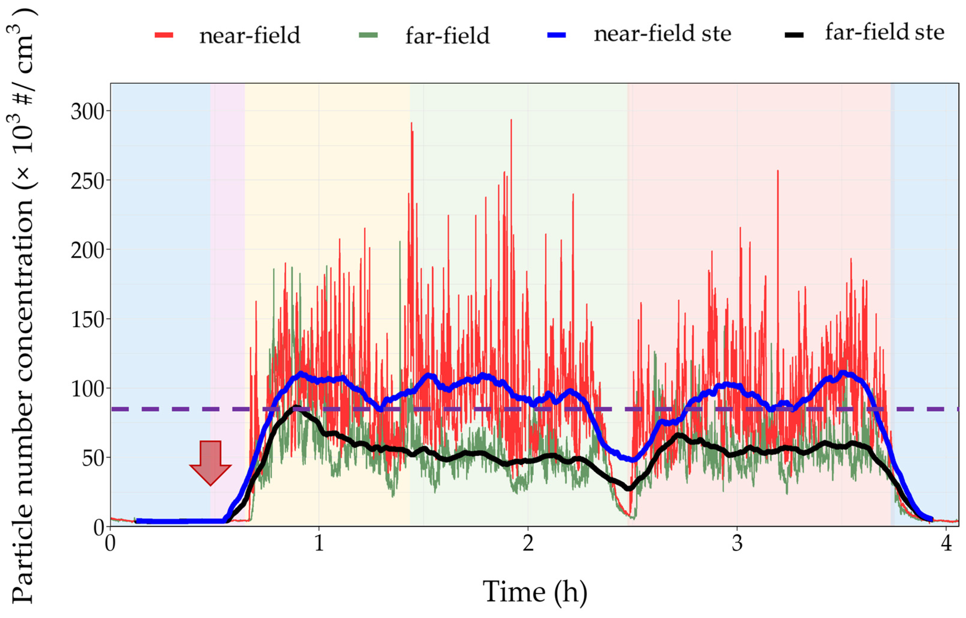
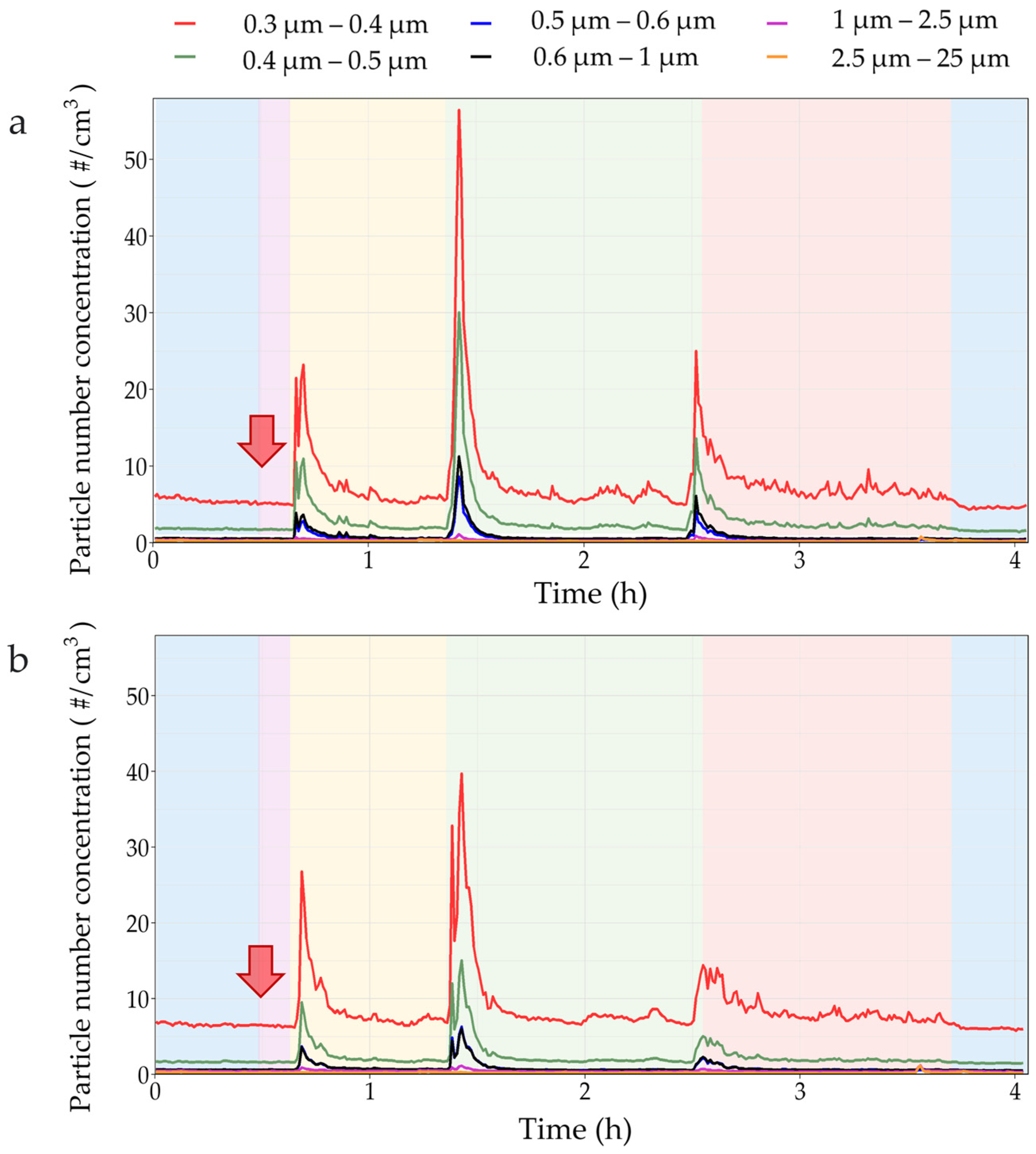
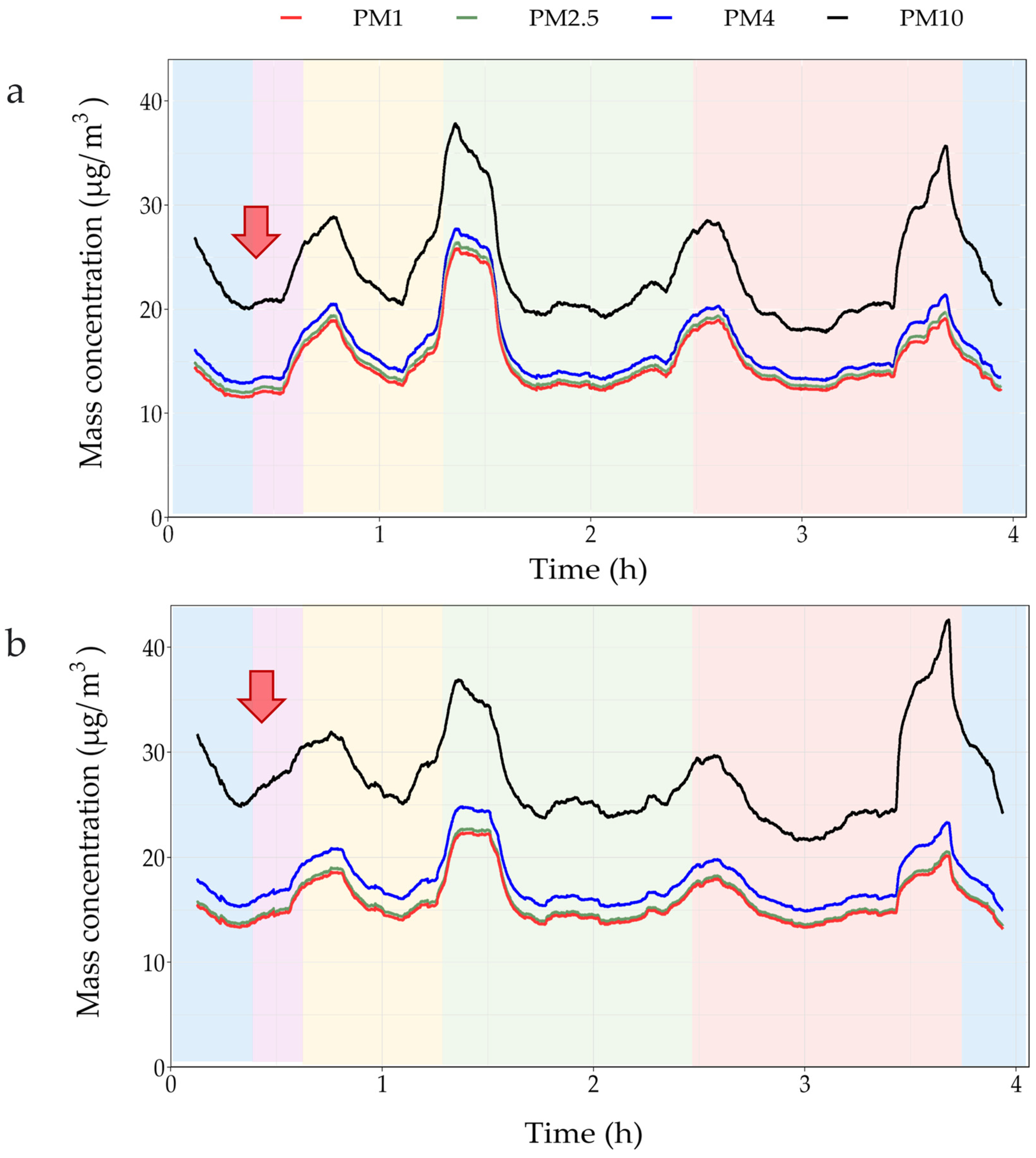
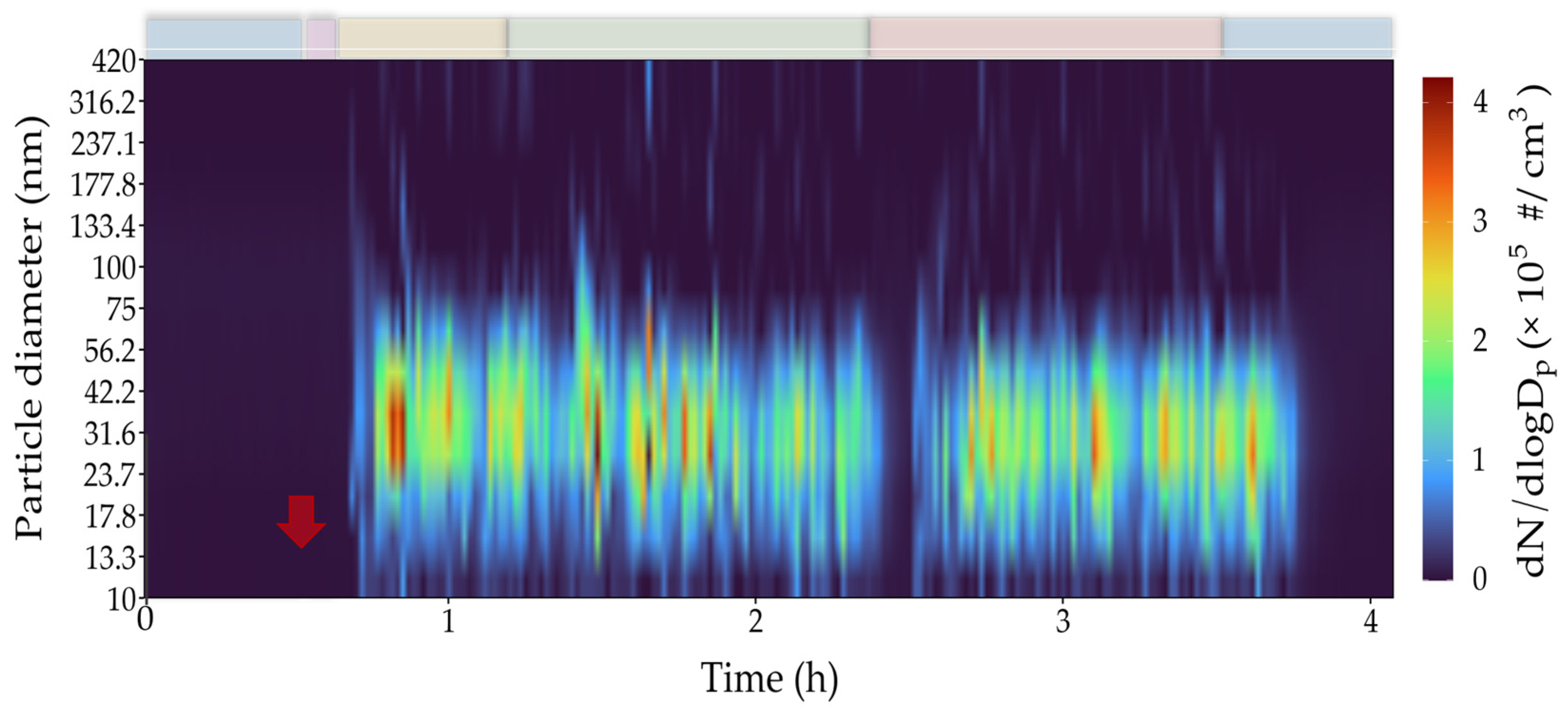
3.2. On-Site Exposure Assessment

Based on the results of the preliminary assessment, the performance of a particle exposure measurement campaign facilitates the evaluation of real-time particle number concentrations, both near-field and far-field, allowing a more accurate exposure assessment. The results are shown in Figure 4, Figure 5, Figure 6 and Figure 7. With the setup described in Section 2.5, the monitoring of the exposure to airborne particles from 10 nm to 25 μm throughout the room was enabled and a quantitative risk assessment was performed.
Near- and far-field particle number concentration measurements of sub-micron particles (<1 μm) (Figure 4) show that using either CNTs or FLG has a negligible effect on the particle number concentrations during the CF sizing. Results showed that during the sizing using either CNTs or FLG as bath solutions for a given CF, particle concentrations ranged from 100,000 to approximately 300,000 particles/cm3. For CPC measurements, using the Nano Reference Values for nanomaterials with densities < 6000 kg/m3 [54], the 15 min short-term exposure limit (STEL) is defined as 80,000 particles/cm3 and the 8 h time-weighted average (TWA) as 40,000 particles/cm3. Both thresholds are surpassed throughout the process in the near-field measurements for the sizing of 6k CF. Focusing on the far-field exposure results, in order to evaluate if the ventilation was sufficient to clear the ambient environment air and for particle concentrations to drop to previous background values, results showed that particle concentrations were between the 15 min STE limit and the 8 h TWA limit, indicating that additional safety control measures would minimise the potential exposure risks.
Proper ventilation in the occupied spaces can be estimated based on the air changes per hour according to the Industrial Ventilation Standard for proper control of the occupational risk [55]. Bello et al. studied the potential particle emissions during dry and wet abrasive machining of composites, highlighting the minimal contribution of CNTs on exposure to airborne nano-scale and sub-micron particles during operation [56]. Overall, the near-field results are well above 100,000 particles per cm3, which, according to the instrument’s manual, limits the reliability of the measurement. Further exploratory measurements could provide more reliable results, but they are out of the scope of this study.
Similarly, Figure 5 shows increased concentrations of particles between 0.3 and 0.4 μm in size in both the near-field and far-field measurements during the overall sizing process. The recorded upsurges in particle concentration for the 0.3–1 μm samples were aligned with the time-logged beginning of the sizing process for the different sizing bath solutions, probably due to the increased residence time of the CFRP in the ovens (Figure 5). These results indicate that in cases of manual labour processes which require constant operator presence, such as changing the sizing bath solution, the use of appropriate PPE is critical (e.g., high-efficiency respiratory protective masks (FFP3)) to prevent the inhalation of the generated airborne particles. Analysing the mass-based concentration measurements from the DustTrak instrument for particles from PM1 to PM10 (Figure 6 and Figure S1, Supplementary Information), particle concentrations were affected mainly by the commencement of the sizing process with each sizing solution, where the same part of the fibre remains in the oven for longer until the bath is changed, while the use of CNTs or FLG did not seem to affect the mass-based concentrations. The different lines of the measuring channels seem to overlap (Figure S1, Supplementary Information); however, when analysing the 15 min average values of the mass-base measurements (Figure 6), similarly to Figure 4, it was observed that upsurges were more pronounced for PM1–PM4 than PM10 both in near-field and far-field measurements. PM10 concentration seems to be elevated in the bath with FLG in the far-field measurement, which is probably related to different particle size profiles and thus seems unrelated to the process and due to an adjacent activity. Based on the particle size distribution (Figure 7), during the sizing of the 6k CF (Figure 7), increased concentrations were recorded for particles smaller than 75 nm for both CNT and FLG baths and below 100 nm for the control experiment without the engineered nanomaterials. For all sizing experiments, the highest values were reached for the size range of 23.7 to 75 nm. This indicates that most released particles cannot penetrate undamaged skin as their size exceeds 20 nm [57]. Additionally, larger particles can accumulate in the olfactory bulb, causing inflammation, while smaller particles can potentially pass through the olfactory nerve, increasing the risk of neurodegenerative effects [25]. Pulmonary and extrapulmonary effects are discussed in the next section.
In all cases, following the completion of each sizing cycle, all particle size concentrations immediately dropped close to the background values. Older research suggests that there is small consensus on exposure assessment methods and metrics (particle number, surface area and mass), although particle number is often dominated by ultrafine or non-engineered nanoparticle sources [58,59,60]. It is worth noting that, although in the current document there is no repeatability of the procedure and exposure campaign, a similar study was previously conducted for the sizing of 6k fibres, showing comparable results [61].

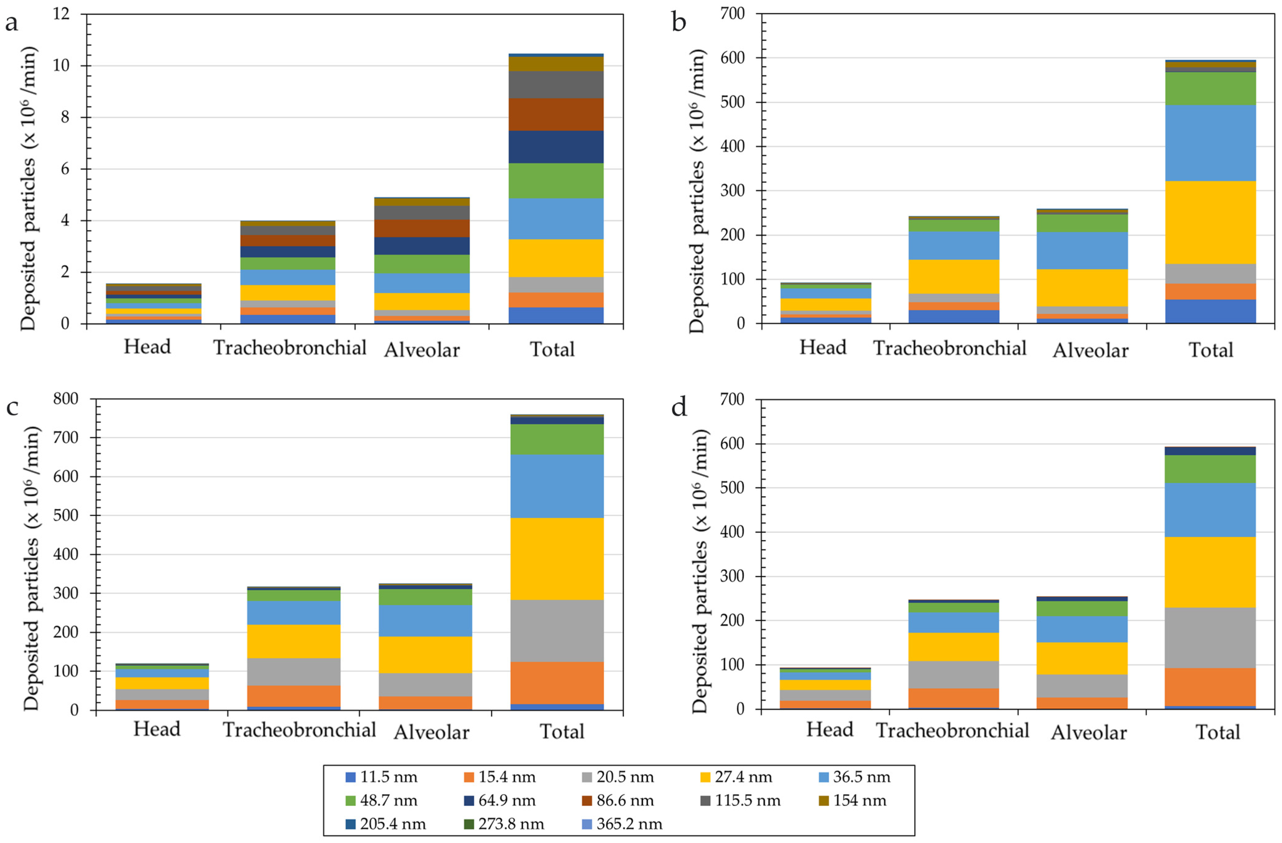
3.3. Respiratory Tract Particle Deposition Analysis

Figure 8 presents an estimation of particles potentially deposited in different sections of the respiratory tract—as analysed by coupling the particle size distribution results obtained by the NanoScan SMPS 3910 and the MPPD model (Figures S2–S5, Supplementary Information)—within one minute in the four distinct process phases of the measurement campaign (background, no bath, bath with MWCNTs, bath with FLG). The results presented are based on (i) the size distribution of the released and background particles and (ii) the deposition of different particle sizes in the respiratory tract. The latter is a standardised model that is mostly defined by the breathing model and the pathway morphology. However, particle size distribution is defined by the materials, processes and process environment. Different materials and process parameters can lead to vastly different size distributions for the released particles. Additionally, background size distributions can be affected by other processes performed in the same environment, cleaning schedule and type, stored materials, etc. During the background measurements, no substantial changes in particle concentration and size distribution were observed; therefore, the results presented in Figure 8a are expected to be indicative of the whole duration of the background. For the other three phases, the minute with the highest particle concentration for each phase was selected and is presented in Figure 8b–d. The MPPD model simulations show an increased fraction deposited in the tracheobronchial region compared to the background. During the background, a similar number of particles are deposited for most of the size channels. However, a swift towards smaller particles is observed during the operation of the pilot line, with most of the deposited particles being between 15 nm and 50 nm. The highest deposition values were observed for particle sizes of 27.4 nm and 36.5 nm. Small particles have a larger relative surface area, leading to an increased chance of absorption and reactivity with the cells.
A review by Thu et al. [62] highlights particle size as a key factor of toxicity, documenting increased toxicity for particles smaller than 50 nm as well as increased occurrence of systemic effects following absorption of the particles and circulation. The pulmonary effects of several nanoforms have been reviewed by Braakhuis et al., with most studies reporting dose-dependent pulmonary inflammation for carbon black and MWCNTs [63]. More severe inflammation was observed for smaller particles. Furthermore, Heinrich et al. reported evidence of lung tumour generation following exposure to carbon black (14 nm diameter) [64]. Raftis and Miller reported the potential of particles smaller than 30 nm to pass into the blood through the alveolar barrier, leading to the risk of damage to the kidneys, the gastrointestinal system, the liver and the reproductive organs [65].

3.4. Study Limitations and Future Research

While this study provides valuable results and analysis concerning the processes that comprise the sizing of carbon fibres, we have acknowledged certain factors that should be noted as potential limitations. Additional proposals for future research are stated below, based on the identified limitations, that will provide further value to this study and the nanomaterials field. One of the limitations of this work is related to the absence of collection and subsequent chemical analysis of the carbon-based nanomaterials due to their similarity to the air sample filters’ substrate (carbon-based polymer filters). Further research with scanning electron microscopy (SEM) analysis could provide more information on the surface morphology of the fibres and additional transmission electron microscopy (TEM) analysis could be used to provide detailed information for the structure and morphology of the fibres on an atomic level, which would affect the properties of the material. This information would facilitate the assessment of hazard potential [66,67].
Furthermore, the same limitation applies to the lack of toxicological analysis on tangled CNTs and FLG [68]. The applied hazard banding approach could lead to uncertain results of the CNTs and FLG analysis due to unknown properties and related effects on human health and the environment. For example, the functionalization of CNTs improves their solubility and biocompatibility and alters their cellular interaction pathways, resulting in much-reduced cytotoxic effects [69,70]. In-depth toxicological analysis would be beneficial in future research to rigorously evaluate the potency and hazard banding of CNTs and FLG.
In our analysis, process isolation between the two sub-processes (desizing and drying), which took place in different furnaces, was not possible. Based on the on-site observations, it is likely that the main emissions originate from the desizing stage, as its furnace operates at a higher temperature than the drying stage. The inability to recognise the main emission contributor (e.g., desizing or drying oven) hinders the design of sufficient safety controls as other emission contributors could be overlooked or not taken into account. The current setup was designed and developed as a continuous manufacturing system; hence, future analysis with process isolation—or the selective operation of units and parts of the setup—and a focus on the desizing part of the process could potentially enhance that theory and provide more accurate results. Additional exposure experiments varying the type and position of additional engineering controls, such as local source ventilation at different positions of the setup, etc., would benefit the optimisation of the room layout since changing these parameters greatly influenced the airflow patterns in the room [71,72]. Finally, this work is related to the limited repeatability of the procedure and the extension to other types of CFs (e.g., 50k CFs).
Measurement studies exist for other configurations, such as polymer processing and additive manufacturing through 3D printing [73,74], that show similar results in terms of airborne hazard exposure. Given that the available engineering controls and the mitigation measures are mapped by established sources, e.g., ISO 45001:2018 [75], it is noted that in exposure studies similar courses of action can be applied. However, the measurement results of one process cannot be extrapolated to a different process. Case-specific measurements and process design are vital to ensure the safety of the operators. It is important to identify the parameters that affect the measurement results in order to make an informed decision on the extrapolation of the data to other configurations or to large-scale industrial settings of the same sizing process.
The assessment of parameters depends on their effect on the results and their potential to be anticipated. Besides quantities, which are the main alterations in large-scale sites and should be easily anticipated, the parameters that are related to the process, such as materials used, process temperature, duration, etc., are the first to be addressed, because different materials mean different toxicity profiles and, hence, different respective acceptable exposure limits. Temperature and duration have the biggest effect on the exposure results, in terms of process specifications, as temperature significantly increases the emission concentrations, and the duration also indirectly increases the emission concentration. Keeping these parameters stable could result in expected emission particle sizes and particle size distribution from the pilot scale and be used to design a safer industrial-scale process line. However, when considering large-scale sites, the workroom parameters, such as workroom volume, and applied controls, like general ventilation, source containment, etc., can vary significantly, leading to uncertainty for the extrapolation of the pilot-scale results. Evidently, in large-scale settings, it is found that space morphology and airflow characteristics are important factors affecting the concentration distribution of human-exhaled contaminants [76]. It is a logical result that aerosol concentration is greatly influenced by the room specifications and ventilation systems and can be significantly reduced by optimisation of parameters to the specific case. Another consideration, regarding dustiness measurements, is the presence of other liquids or moisture content that affects the release of dust from powders [77]. In large settings, the simultaneous activities should be taken into account, because they increase the difficulty of isolating the emissions deriving from each process and can potentially increase the respirable particulate matter and the background measurements that are used as reference for the assessment of source emissions. Summarising the process-related parameters as well as the parameters related to workroom specifications and simultaneous activities poses a challenge to the interpretation of the results in different settings. Either the correlation with different materials and processes or the correlation of pilot-scale results with larger scale settings is not proposed. Overall, in health and safety assessments the preferred course of action is a case-specific approach that will isolate, to the extent that is possible, the process and produce reliable results. Further analysis such as computational fluid dynamic (CFD) simulations coupled with the pilot-scale sizing process results can enhance the certainty and applicability of the data, in order to achieve safer design processes and setups.

4. Conclusions

This study presents a comprehensive approach for the evaluation of the occupational hazards during the sizing of 6k carbon fibres using functionalized engineered nanomaterials (CNTs and FLG). A tiered approach was followed based on EN 17058, while hazard and exposure banding highlighted the need for on-site measurements due to the moderate hazard level of the materials used and the increased exposure potential due to the process conditions. Additionally, a process hazard analysis based on the ‘what-if’ methodology investigated hypothetical scenarios of process malfunctioning of utilities and ancillaries, as well as human error, which could lead to increased exposure potential to airborne hazardous substances, enabling the analysis of effective mitigation measures. Measurements showed increased concentrations of sub-micron particles throughout all sizing processes. Increased concentrations of larger particles were also observed at the beginning of each sizing process, which can be attributed to the prolonged idle time of the CFs in the desizing and drying ovens. The selection of sizing had a negligible effect on the overall exposure potential, with the use of CNTs or FLG leading to similar results. In order to minimise the exposure potential, upgrades of the engineering controls (e.g., local ventilation) were recommended and taken into consideration in the design for further optimisation of the pilot line since the release of particles below 50 nm poses a high risk due to their higher toxicity potential and deposition in the alveoli causing adverse health effects. Further studies on the toxicological and morphological analyses of carbon-based engineered nanomaterials would provide a greater understanding of their hazard potential, while process isolation between the various steps would allow for more effective implementation of hazard control systems and support a safe-by-design approach.

Supplementary Materials

The following supporting information can be downloaded at https://www.mdpi.com/article/10.3390/safety11010011/s1. Figure S1: (a) Near- and (b) far-field mass-based concentration measurements from DustTrak DRX 8534 over the operation time of the 6k carbon fibre sizing process. Shaded areas: blue: background; purple: ovens on; yellow: no bath; green: bath with MWCNTs; red: bath with FLG. Arrow: ovens are on; Figure S2: Timestamp of the (a) particle size distribution during background measurements (before CF sizing process) using the NanoScan SMSP 3910 and (b) size distribution of deposited particles in the respiratory tract via the MPPD model; Figure S3: Timestamp of the (a) particle size distribution during CF sizing process with no bath (NanoScan SMSP 3910) and (b) size distribution of deposited particles in the respiratory tract via the MPPD model; Figure S4: Timestamp of the (a) particle size distribution during the CF sizing process with an MWCNT bath (NanoScan SMSP 3910) and (b) size distribution of deposited particles in the respiratory tract via the MPPD model; Figure S5: Timestamp of the (a) particle size distribution during the CF sizing process with FLG (NanoScan SMSP 3910) and (b) size distribution of deposited particles in the respiratory tract via the MPPD model; Table S1: Hazard banding by hazard statement for the materials used during the fibre sizing process.

Author Contributions

Conceptualization, S.D. and E.P.K.; methodology, S.D. and S.S.; investigation, S.D. and S.S.; resources, D.S., C.C. and E.P.K.; writing—original draft preparation, S.D., S.S., A.K. and D.S.; writing—review and editing, S.D., D.S. and E.P.K.; visualisation, S.D. and S.S.; supervision, E.P.K.; project administration, E.P.K.; funding acquisition, E.P.K. All authors have read and agreed to the published version of the manuscript.

Funding

This research was funded by the European Union’s Horizon 2020 Research and Innovation Programme Carbo4Power project (Grant No.: 953192).

Institutional Review Board Statement

Not applicable.

Informed Consent Statement

Not applicable.

Data Availability Statement

Data are contained within the article and Supplementary Materials.

Acknowledgments

The authors would like to thank Haydale Ltd. for the supply of functionalised nanomaterials.

Conflicts of Interest

The authors declare no conflicts of interest.

References

  1. Ahmad, H.; Markina, A.A.; Porotnikov, M.V.; Ahmad, F. A Review of Carbon Fiber Materials in Automotive Industry—IOPscience. IOP Conf. Ser. Mater. Sci. Eng. 2020, 971, 032011. [Google Scholar] [CrossRef]
  2. Williams, G.; Trask, R.; Bond, I. A Self-Healing Carbon Fibre Reinforced Polymer for Aerospace Applications. Compos. Part A Appl. Sci. Manuf. 2007, 38, 1525–1532. [Google Scholar] [CrossRef]
  3. Vijayan, D.S.; Sivasuriyan, A.; Devarajan, P.; Stefańska, A.; Wodzyński, Ł.; Koda, E. Carbon Fibre-Reinforced Polymer (CFRP) Composites in Civil Engineering Application—A Comprehensive Review. Buildings 2023, 13, 1509. [Google Scholar] [CrossRef]
  4. Harussani, M.M.; Sapuan, S.M.; Nadeem, G.; Rafin, T.; Kirubaanand, W. Recent Applications of Carbon-Based Composites in Defence Industry: A Review. Def. Technol. 2022, 18, 1281–1300. [Google Scholar] [CrossRef]
  5. Ismail, K.B.M.; Kumar, M.A.; Mahalingam, S.; Raj, B.; Kim, J. Carbon Fiber-Reinforced Polymers for Energy Storage Applications. J. Energy Storage 2024, 84, 110931. [Google Scholar] [CrossRef]
  6. Teng, H.; Li, S.; Cao, Z.; Li, S.; Li, C.; Ko, T.J. Carbon Fiber Composites for Large-Scale Wind Turbine Blades: Applicability Study and Comprehensive Evaluation in China. J. Mar. Sci. Eng. 2023, 11, 624. [Google Scholar] [CrossRef]
  7. Gonabadi, H.; Oila, A.; Yadav, A.; Bull, S. Structural Performance of Composite Tidal Turbine Blades. Compos. Struct. 2021, 278, 114679. [Google Scholar] [CrossRef]
  8. Wang, J.; Schlagenhauf, L.; Setyan, A. Transformation of the Released Asbestos, Carbon Fibers and Carbon Nanotubes from Composite Materials and the Changes of Their Potential Health Impacts. J. Nanobiotechnol. 2017, 15, 15. [Google Scholar] [CrossRef]
  9. Qiu, J.; Li, J.; Yuan, Z.; Zeng, H.; Chen, X. Surface Modification of Carbon Fibres for Interface Improvement in Textile Composites. Appl. Compos. Mater. 2018, 25, 853–860. [Google Scholar] [CrossRef]
  10. Fortune Business Insight Carbon Fiber Market Size, Share & Industry Analysis 2024-20232. Available online: https://www.fortunebusinessinsights.com/industry-reports/carbon-fiber-market-101719 (accessed on 28 October 2024).
  11. Jaber, A.A.; Abbas, S.A.; Farah, A.A.; Kopeć, K.K.; Alsalik, Y.M.; Tayeb, M.A.; Verghese, N. Effect of Fiber Sizing Levels on the Mechanical Properties of Carbon Fiber-Reinforced Thermoset Composites. Polymers 2023, 15, 4678. [Google Scholar] [CrossRef]
  12. Mamalis, D.; Flanagan, T.; Ó Brádaigh, C.M. Effect of Fibre Straightness and Sizing in Carbon Fibre Reinforced Powder Epoxy Composites. Compos. Part A Appl. Sci. Manuf. 2018, 110, 93–105. [Google Scholar] [CrossRef]
  13. Matveeva, A.Y.; Lomov, S.V.; Gorbatikh, L. Debonding at the Fiber/Matrix Interface in Carbon Nanotube Reinforced Composites: Modelling Investigation. Comput. Mater. Sci. 2019, 159, 412–419. [Google Scholar] [CrossRef]
  14. Yang, T.; Zhao, Y.; Liu, H.; Sun, M.; Xiong, S. Effect of Sizing Agents on Surface Properties of Carbon Fibers and Interfacial Adhesion of Carbon Fiber/Bismaleimide Composites. ACS Omega 2021, 6, 23028–23037. [Google Scholar] [CrossRef]
  15. Aoki, R.; Yamaguchi, A.; Hashimoto, T.; Urushisaki, M.; Sakaguchi, T.; Kawabe, K.; Kondo, K.; Iyo, H. Preparation of Carbon Fibers Coated with Epoxy Sizing Agents Containing Degradable Acetal Linkages and Synthesis of Carbon Fiber-Reinforced Plastics (CFRPs) for Chemical Recycling. Polym. J. 2019, 51, 909–920. [Google Scholar] [CrossRef]
  16. Bao, J.; Li, Y.; Zhong, X.; Chen, X. The Effect of Sizing Agent of Carbon Fibre on the Interface of Electron Beam Cured Composites. Adv. Compos. Lett. 2011, 20, 096369351102000601. [Google Scholar] [CrossRef]
  17. Pawar, S.S.; Hutchinson, S.A.; Eyckens, D.J.; Stojcevski, F.; Hayne, D.J.; Gengenbach, T.R.; Razal, J.M.; Henderson, L.C. Carbon Fiber Sizing Agents Based on Renewable Terpenes. Compos. Sci. Technol. 2022, 220, 109280. [Google Scholar] [CrossRef]
  18. Pozegic, T.R.; Anguita, J.V.; Hamerton, I.; Jayawardena, K.D.G.I.; Chen, J.-S.; Stolojan, V.; Ballocchi, P.; Walsh, R.; Silva, S.R.P. Multi-Functional Carbon Fibre Composites Using Carbon Nanotubes as an Alternative to Polymer Sizing. Sci. Rep. 2016, 6, 37334. [Google Scholar] [CrossRef]
  19. Jäger, M.; Zabihi, O.; Ahmadi, M.; Li, Q.; Depalmeanar, A.; Naebe, M. Nano-Enhanced Interface in Carbon Fibre Polymer Composite Using Halloysite Nanotubes. Compos. Part A Appl. Sci. Manuf. 2018, 109, 115–123. [Google Scholar] [CrossRef]
  20. Balaban, A.C.; Toygar, M.E. Usage of Nanomaterials on Carbon Fibre/Epoxy Composites for Improvement of Their Material Properties. Procedia Struct. Integr. 2022, 42, 292–298. [Google Scholar] [CrossRef]
  21. Semitekolos, D.; Papadopoulos, I.; Anagnou, S.; Dashtbozorg, B.; Li, X.; Dong, H.; Charitidis, C.A. Nanomaterial-Enhanced Sizings: Design and Optimisation of a Pilot-Scale Fibre Sizing Line. Fibers 2024, 12, 16. [Google Scholar] [CrossRef]
  22. Asmatulu, E.; Alonayni, A.; Alamir, M. Safety Concerns in Composite Manufacturing and Machining. In Proceedings of the Behavior and Mechanics of Multifunctional Materials and Composites XII, Denver, CO, USA, 5–8 March 2018; Naguib, H.E., Ed.; SPIE: Bellingham, WA, USA, 2018; Volume 10596, p. 1059623. [Google Scholar]
  23. Kehren, D.; Simonow, B.; Bäger, D.; Dziurowitz, N.; Wenzlaff, D.; Thim, C.; Neuhoff, J.; Meyer-Plath, A.; Plitzko, S. Release of Respirable Fibrous Dust from Carbon Fibers Due to Splitting along the Fiber Axis. Aerosol Air Qual. Res. 2019, 19, 2185–2195. [Google Scholar] [CrossRef]
  24. Tölle, L.; Monsé, C.; Rosenkranz, N.; Haibel, N.; Walter, D.; Bünger, J.; Hopp, M.; Westphal, G.A. Characterization of Fiber Dust Resulting from Recycling of Carbon Fiber-Reinforced Thermoplastics (CFRP) and Their Cell Toxicity. J. Mater. Sci. Chem. Eng. 2022, 10, 1–16. [Google Scholar] [CrossRef]
  25. Oberdörster, G.; Oberdörster, E.; Oberdörster, J. Nanotoxicology: An Emerging Discipline Evolving from Studies of Ultrafine Particles. Environ. Health Perspect 2005, 113, 823–839. [Google Scholar] [CrossRef]
  26. Kelly, F.J.; Fussell, J.C. Toxicity of Airborne Particles—Established Evidence, Knowledge Gaps and Emerging Areas of Importance. Philos. Trans. Ser. A Math. Phys. Eng. Sci. 2020, 378, 20190322. [Google Scholar] [CrossRef] [PubMed]
  27. Marval, J.; Tronville, P. Ultrafine Particles: A Review about Their Health Effects, Presence, Generation, and Measurement in Indoor Environments. Build. Environ. 2022, 216, 108992. [Google Scholar] [CrossRef]
  28. Ganguly, P.; Breen, A.; Pillai, S.C. Toxicity of Nanomaterials: Exposure, Pathways, Assessment, and Recent Advances. ACS Biomater. Sci. Eng. 2018, 4, 2237–2275. [Google Scholar] [CrossRef] [PubMed]
  29. McCormick, S.; Niang, M.; Dahm, M.M. Occupational Exposures to Engineered Nanomaterials: A Review of Workplace Exposure Assessment Methods. Curr. Environ. Health Rep. 2021, 8, 223–234. [Google Scholar] [CrossRef]
  30. Borm, P.J.; Robbins, D.; Haubold, S.; Kuhlbusch, T.; Fissan, H.; Donaldson, K.; Schins, R.; Stone, V.; Kreyling, W.; Lademann, J.; et al. The Potential Risks of Nanomaterials: A Review Carried out for ECETOC. Part. Fibre Toxicol. 2006, 3, 11. [Google Scholar] [CrossRef]
  31. Ding, Y.; Kuhlbusch, T.A.J.; Van Tongeren, M.; Jiménez, A.S.; Tuinman, I.; Chen, R.; Alvarez, I.L.; Mikolajczyk, U.; Nickel, C.; Meyer, J.; et al. Airborne Engineered Nanomaterials in the Workplace—A Review of Release and Worker Exposure during Nanomaterial Production and Handling Processes. J. Hazard. Mater. 2017, 322, 17–28. [Google Scholar] [CrossRef] [PubMed]
  32. Heitbrink, W.A.; Lo, L.-M.; Dunn, K.H. Exposure Controls for Nanomaterials at Three Manufacturing Sites. J. Occup. Environ. Hyg. 2015, 12, 16–28. [Google Scholar] [CrossRef]
  33. Kokkinopoulos, I.; Karayannis, P.; Saliakas, S.; Damilos, S.; Koumoulos, E.P. Employing Nanosafety Standards in a Nanomaterial Research Environment: Lessons Learned and Refinement Potential. Standards 2022, 2, 490–502. [Google Scholar] [CrossRef]
  34. Zhang, C.; Wu, L.; de Perrot, M.; Zhao, X. Carbon Nanotubes: A Summary of Beneficial and Dangerous Aspects of an Increasingly Popular Group of Nanomaterials. Front. Oncol. 2021, 11, 693814. [Google Scholar] [CrossRef] [PubMed]
  35. Madannejad, R.; Shoaie, N.; Jahanpeyma, F.; Darvishi, M.H.; Azimzadeh, M.; Javadi, H. Toxicity of Carbon-Based Nanomaterials: Reviewing Recent Reports in Medical and Biological Systems. Chem.-Biol. Interact. 2019, 307, 206–222. [Google Scholar] [CrossRef]
  36. Ou, L.; Song, B.; Liang, H.; Liu, J.; Feng, X.; Deng, B.; Sun, T.; Shao, L. Toxicity of Graphene-Family Nanoparticles: A General Review of the Origins and Mechanisms. Part. Fibre Toxicol. 2016, 13, 57. [Google Scholar] [CrossRef]
  37. Kirešová, S.; Guzan, M.; Sobota, B. Using Low-Cost Sensors for Measuring and Monitoring Particulate Matter with a Focus on Fine and Ultrafine Particles. Atmosphere 2023, 14, 324. [Google Scholar] [CrossRef]
  38. Karayannis, P.; Petrakli, F.; Gkika, A.; Koumoulos, E.P. 3D-Printed Lab-on-a-Chip Diagnostic Systems-Developing a Safe-by-Design Manufacturing Approach. Micromachines 2019, 10, 825. [Google Scholar] [CrossRef] [PubMed]
  39. Subramanian, V.; Peijnenburg, W.J.G.M.; Vijver, M.G.; Blanco, C.F.; Cucurachi, S.; Guinée, J.B. Approaches to Implement Safe by Design in Early Product Design through Combining Risk Assessment and Life Cycle Assessment. Chemosphere 2023, 311, 137080. [Google Scholar] [CrossRef]
  40. EN 17058:2018; Workplace Exposure—Assessment of Exposure by Inhalation of Nano-Objects and Their Aggregates and Agglomerates. European Committee for Standardization: Brussels, Belgium, 2018.
  41. ISO/TS 12901-2:2014; Nanotechnologies—Occupational Risk Management Applied to Engineered Nanomaterials—Part 2: Use of the Control Banding Approach. International Organization for Standardization: Geneva, Switzerland, 2014.
  42. C&L Inventory—ECHA. Available online: https://echa.europa.eu/information-on-chemicals/cl-inventory-database (accessed on 17 October 2022).
  43. Kwon, S.-J.; Choi, S.-W.; Lee, E.-B. Hazard Identification and Risk Assessment During Simultaneous Operations in Industrial Plant Maintenance Based on Job Safety Analysis. Sustainability 2024, 16, 9277. [Google Scholar] [CrossRef]
  44. Lyon, B.K.; Popov, G. The Power of What If: Assessing and Understanding Risk. Prof. Saf. 2020, 65, 36–43. [Google Scholar]
  45. ISO/TR 12885:2018; Nanotechnologies—Health and Safety Practices in Occupational Settings. European Committee for Standardization: Geneva, Switzerland, 2018.
  46. Stephens, B.; Azimi, P.; El Orch, Z.; Ramos, T. Ultrafine Particle Emissions from Desktop 3D Printers. Atmos. Environ. 2013, 79, 334–339. [Google Scholar] [CrossRef]
  47. Saliakas, S.; Karayannis, P.; Kokkinopoulos, I.; Damilos, S.; Gkartzou, E.; Zouboulis, P.; Karatza, A.; Koumoulos, E.P. Fused Filament Fabrication 3D Printing: Quantification of Exposure to Airborne Particles. J. Compos. Sci. 2022, 6, 119. [Google Scholar] [CrossRef]
  48. Lamon, L.; Asturiol, D.; Vilchez, A.; Cabellos, J.; Damásio, J.; Janer, G.; Richarz, A.; Worth, A. Physiologically Based Mathematical Models of Nanomaterials for Regulatory Toxicology: A Review. Comput. Toxicol. 2019, 9, 133–142. [Google Scholar] [CrossRef] [PubMed]
  49. Brief Profile—ECHA—Carbon Black. Available online: https://echa.europa.eu/brief-profile/-/briefprofile/100.014.191 (accessed on 30 October 2024).
  50. Koch, A.; Friederici, L.; Fiala, P.; Springer, A.; Di Bucchianico, S.; Stintz, M.; Frank, M.; Rüger, C.P.; Streibel, T.; Zimmermann, R. Impact of Thermal Stress on Abrasive Dust from a Carbon Fiber-Reinforced Concrete Composite. Fibers 2022, 10, 39. [Google Scholar] [CrossRef]
  51. American Chemical Society. Identifying and Evaluating Hazards in Research Laboratories; American Chemical Society: Washington, DC, USA, 2015. [Google Scholar]
  52. Nakanishi, J.; Morimoto, Y.; Ogura, I.; Kobayashi, N.; Naya, M.; Ema, M.; Endoh, S.; Shimada, M.; Ogami, A.; Myojyo, T.; et al. Risk Assessment of the Carbon Nanotube Group. Risk Anal. 2015, 35, 1940. [Google Scholar] [CrossRef] [PubMed]
  53. C&L Inventory—ECHA—Tangled Multi-Walled Carbon Nanotubes. Available online: https://echa.europa.eu/information-on-chemicals/cl-inventory-database/-/discli/details/256880 (accessed on 29 October 2024).
  54. van Broekhuizen, P.; van Veelen, W.; Streekstra, W.-H.; Schulte, P.; Reijnders, L. Exposure Limits for Nanoparticles: Report of an International Workshop on Nano Reference Values. Ann. Occup. Hyg. 2012, 56, 515–524. [Google Scholar] [CrossRef] [PubMed]
  55. American Conference of Governmental Industrial Hygienists. Industrial Ventilation: A Manual of Recommended Practice, 23rd ed.; American Conference of Governmental Industrial Hygienists, Inc.: Cincinnati, OH, USA, 1988; ISBN 1-882417-22-4. [Google Scholar]
  56. Bello, D.; Wardle, B.L.; Yamamoto, N.; Guzman deVilloria, R.; Garcia, E.J.; Hart, A.J.; Ahn, K.; Ellenbecker, M.J.; Hallock, M. Exposure to Nanoscale Particles and Fibers during Machining of Hybrid Advanced Composites Containing Carbon Nanotubes. J. Nanopart. Res. 2009, 11, 231–249. [Google Scholar] [CrossRef]
  57. Larese Filon, F.; Mauro, M.; Adami, G.; Bovenzi, M.; Crosera, M. Nanoparticles Skin Absorption: New Aspects for a Safety Profile Evaluation. Regul. Toxicol. Pharmacol. 2015, 72, 310–322. [Google Scholar] [CrossRef] [PubMed]
  58. Erdely, A.; Dahm, M.; Chen, B.T.; Zeidler-Erdely, P.C.; Fernback, J.E.; Birch, M.E.; Evans, D.E.; Kashon, M.L.; Deddens, J.A.; Hulderman, T.; et al. Carbon Nanotube Dosimetry: From Workplace Exposure Assessment to Inhalation Toxicology. Part. Fibre Toxicol. 2013, 10, 53. [Google Scholar] [CrossRef]
  59. Dahm, M.M.; Evans, D.E.; Schubauer-Berigan, M.K.; Birch, M.E.; Deddens, J.A. Occupational Exposure Assessment in Carbon Nanotube and Nanofiber Primary and Secondary Manufacturers: Mobile Direct-Reading Sampling. Ann. Occup. Hyg. 2013, 57, 328–344. [Google Scholar] [CrossRef]
  60. Evans, D.E.; Ku, B.K.; Birch, M.E.; Dunn, K.H. Aerosol Monitoring during Carbon Nanofiber Production: Mobile Direct-Reading Sampling. Ann. Occup. Hyg. 2010, 54, 514–531. [Google Scholar] [CrossRef] [PubMed]
  61. Damilos, S.; Kokkinopoulos, I.; Semitekolos, D.; Podara, C.V.; Antonaropoulos, G.; Saliakas, S.; Karayannis, P.; Charitidis, C.; Koumoulos, E.P. Occupational Risk Management of Engineered Nanomaterials: A Carbon Fibre Sizing Pilot Line Case Study. In Proceedings of the Conference Proceedings: 2nd International Conference on Polymer Process Innovation, Lavrion, Greece, 15–16 September 2022; ISBN 978-94-6466-761-5. [Google Scholar]
  62. Thu, H.E.; Haider, M.; Khan, S.; Sohail, M.; Hussain, Z. Nanotoxicity Induced by Nanomaterials: A Review of Factors Affecting Nanotoxicity and Possible Adaptations. OpenNano 2023, 14, 100190. [Google Scholar] [CrossRef]
  63. Braakhuis, H.M.; Park, M.V.; Gosens, I.; De Jong, W.H.; Cassee, F.R. Physicochemical Characteristics of Nanomaterials That Affect Pulmonary Inflammation. Part. Fibre Toxicol. 2014, 11, 18. [Google Scholar] [CrossRef] [PubMed]
  64. Heinrich, U.; Fuhst, R.; Rittinghausen, S.; Creutzenberg, O.; Bellmann, B.; Koch, W.; Levsen, K. Chronic Inhalation Exposure of Wistar Rats and Two Different Strains of Mice to Diesel Engine Exhaust, Carbon Black, and Titanium Dioxide. Inhal. Toxicol. 1995, 7, 533–556. [Google Scholar] [CrossRef]
  65. Raftis, J.B.; Miller, M.R. Nanoparticle Translocation and Multi-Organ Toxicity: A Particularly Small Problem. Nano Today 2019, 26, 8–12. [Google Scholar] [CrossRef]
  66. Hoshyaripour, G.A.; Bachmann, V.; Förstner, J.; Steiner, A.; Vogel, H.; Wagner, F.; Walter, C.; Vogel, B. Effects of Particle Nonsphericity on Dust Optical Properties in a Forecast System: Implications for Model-Observation Comparison. J. Geophys. Res. Atmos. 2019, 124, 7164–7178. [Google Scholar] [CrossRef]
  67. Mallios, S.A.; Daskalopoulou, V.; Amiridis, V. Modeling of the Electrical Interaction between Desert Dust Particles and the Earth’s Atmosphere. J. Aerosol Sci. 2022, 165, 106044. [Google Scholar] [CrossRef]
  68. Federal Institute for Occupational Safety and Health. Sustance Evaluation Report as Required by REACH Article 48 and Evaluation Report for Multi-Walled Carbon Nanotubes (MWCNT), Synthetic Graphite in Tubular Shape and Tangled EC No 936-414-1/701-160-0; Federal Institute for Occupational Safety and Health: Dortmund, Germany, 2020. [Google Scholar]
  69. Vardharajula, S.; Ali, S.Z.; Tiwari, P.M.; Eroğlu, E.; Vig, K.; Dennis, V.A.; Singh, S.R. Functionalized Carbon Nanotubes: Biomedical Applications. Int. J. Nanomed. 2012, 7, 5361. [Google Scholar] [CrossRef]
  70. Mohammadi, E.; Zeinali, M.; Mohammadi-Sardoo, M.; Iranpour, M.; Behnam, B.; Mandegary, A. The Effects of Functionalization of Carbon Nanotubes on Toxicological Parameters in Mice. Hum. Exp. Toxicol. 2020, 39, 1147–1167. [Google Scholar] [CrossRef]
  71. Quang, T.N.; He, C.; Morawska, L.; Knibbs, L.D. Influence of Ventilation and Filtration on Indoor Particle Concentrations in Urban Office Buildings. Atmos. Environ. 2013, 79, 41–52. [Google Scholar] [CrossRef]
  72. D’Alicandro, A.C.; Mauro, A. Effects of Operating Room Layout and Ventilation System on Ultrafine Particle Transport and Deposition. Atmos. Environ. 2022, 270, 118901. [Google Scholar] [CrossRef]
  73. Karayannis, P.; Saliakas, S.; Kokkinopoulos, I.; Damilos, S.; Koumoulos, E.P.; Gkartzou, E.; Gomez, J.; Charitidis, C. Facilitating Safe FFF 3D Printing: A Prototype Material Case Study. Sustainability 2022, 14, 3046. [Google Scholar] [CrossRef]
  74. Saliakas, S.; Damilos, S.; Karamitrou, M.; Trompeta, A.-F.; Milickovic, T.K.; Charitidis, C.; Koumoulos, E.P. Integrating Exposure Assessment and Process Hazard Analysis: The Nano-Enabled 3D Printing Filament Extrusion Case. Polymers 2023, 15, 2836. [Google Scholar] [CrossRef] [PubMed]
  75. ISO 45001:2018; Occupational Health and Safety Management Systems—Requirements with Guidance for Use. International Organization for Standardization: Geneva, Switzerland, 2018.
  76. Wang, J.; Pan, Z.; Tang, H.; Guo, W. Assessment of Airborne Viral Transmission Risks in a Large-Scale Building Using Onsite Measurements and CFD Method. J. Build. Eng. 2024, 95, 110222. [Google Scholar] [CrossRef]
  77. Evans, D. Chapter AD: Quantification of Airborne Dusts from Powders. In NIOSH Manual of Analytical Methods (NMAM), 5th ed.; Centers for Disease Control and Prevention—National Institute for Occupational Safety and Health (NIOSH): Cincinnati, OI, USA, 2016. [Google Scholar]
Figure 1. Illustration of the carbon fibre sizing process line.
Safety 11 00011 g001
Figure 2. (a) Top-down illustration of carbon fibre sizing pilot line, with the equipment positioned at the (b) near- and (c) far-field, and (d) measurement size range of the exposure equipment used in the exposure campaign.
Safety 11 00011 g002
Figure 3. SEM pictures of the carbon fibres (a) before any sizing treatment (control), (b) after sizing with MWCNTs and (c) after sizing with FLG. The red square in (b) shows a magnified area of the CF covered with CNTs.
Safety 11 00011 g003
Figure 4. Near- and far-field particle number concentration measurements from CPC3007 over the operation time of the carbon fibre sizing process on 6k CF. Shaded areas: blue: background; purple: ovens on; yellow: no bath; green: bath with MWCNTs; red: bath with FLG. Red arrow: time when ovens are on. STE lines represent the 15 min average values. Dashed line represents the 15 min short-term exposure limit (STEL) at 80,000 particles/cm3.
Safety 11 00011 g004
Figure 5. (a) Near- and (b) far-field particle number concentration measurements from Aerotrak 9306-V2 over the operation time of the 6k carbon fibre sizing process. Shaded areas: blue: background; purple: ovens on; yellow: no bath; green: bath with MWCNTs; red: bath with FLG. Red arrows: time when ovens are on.
Safety 11 00011 g005
Figure 6. The 15 min average values of (a) near- and (b) far-field mass-based concentration measurements from DustTrak DRX 8534 over the operation time of the 6k carbon fibre sizing process. Shaded areas: blue: background; purple: ovens on; yellow: no bath; green: bath with MWCNTs; red: bath with FLG. Red arrows: time when ovens are on.
Safety 11 00011 g006
Figure 7. Particle size distribution from NanoScan SMSP 3910 of the emitted particles over the operation time of the 6k carbon fibre sizing process. Coloured scale bar on the top of the figure represents the process steps: blue: background; purple: ovens on; yellow: no bath; green: bath with MWCNTs; red: bath with FLG. Red arrow: time when ovens are on.
Safety 11 00011 g007
Figure 8. Number of particles (at peak times) potentially deposited in the respiratory tract during the operation of the 6k carbon fibre sizing process: (a) background, (b) no bath, (c) bath with MWCNTs and (d) bath with FLG.
Safety 11 00011 g008
Table 1. Basic exposure-related information from the pilot line for the preliminary assessment.
ProcessCarbon fibre sizing line
Release/exposure expectedEmission of particles (ultrafine and microscale) due to partial decomposition and thermal degradation of the polymer resin
Workroom characteristicsVolume: ≈212 m3
Temperature: 24–30 °C
Relative humidity: 43–48%
Secondary processes conducted within the workroomPreparation of nanomaterial sizing solution
Materials usedCarbon fibres: 6k CFs
Sizing solution: Epoxy sizing agent, Triton X100 and nanomaterials (MWCNTs or FLG)
Process automationManual process initiation (print start) and finish (print removal); sizing process is automated and requires only periodic progress monitoring
Manual stop and fibre removal in case of critical defects and errors
Process containmentThe sizing line is not contained in a fume hood
The sub-process of nanomaterial sizing solution preparation takes place under a fume hood
Process durationCarbon fibre sizing requires 15 h of operation per week
Preparation of nanomaterial sizing solution takes place once per week and requires 2 h per week
Employees associated with the processTwo employees directly involved
Work patternsOperators enter the sizing pilot line room for start/stop and periodic inspection during the process
Cleaning is compulsory at the end of each batch of production
Periodic inspections take place for repair and maintenance purposes
MaintenanceCleaning the line rollers, removing carbon fibres, disposing of the bath solution and cleaning the bath equipment
Primary particle emission sourceCarbon fibre sizing line
Incidental particle emission sourcesNo other instruments that can lead to particle generation are used within the specific workroom during the sizing operations; no apparent sources of significant incidental ultrafine particle emissions; general workplace dust particles may be present; disturbance of settled/deposited particles on work surfaces may occur (e.g., due to air condition airflow, open windows)
Current controls appliedGeneral ventilation
Full-face masks with P3 filters available in the workplace
Table 2. “What if” process hazard analysis of the carbon fibre sizing pilot line.
IDWhat-If…CausesConsequencesControlsRecommendations
1Carbon fibre is entangled in line/roller.Improper placement of carbon fibre.(i) Halting of operation.
(ii) Increased residence time of CF in the oven leading to the elevated release of airborne (nano)particles.
Standard operating procedures in place.Training operators and using a checklist to ensure proper placement of the carbon fibre.
2Rollers stop working.Motor malfunctions and stops working.(i) Halting of operation. (ii) Increased residence time of CF in the oven leading to the elevated release of airborne (nano)particles.Inspection before sizing operation.Periodic maintenance.
3Oven thermostats malfunction.Dirt and particulate matter accumulate.In case of increased temperature, elevated release of airborne (nano)particles.Standard operating procedures in place.Periodic maintenance and risk assessment/standard operating procedures in place for immediate action.
4Sizing bath solution agitator stops working.Damaged shaft damaged wires.Unevenly dispersed engineered nanomaterials in the sizing solution, requiring the process to restart, thus increasing potential exposure to airborne (nano)particles.Standard operating procedures in place.Periodic maintenance and risk assessment/standard operating procedures in place for immediate action.
5Sizing bath solution agitator rotates at extreme speeds.Rotation controller malfunctions.Spillage of engineered nanomaterials resulting in an emission source.Standard operating procedures in place.Periodic maintenance and risk assessment/standard operating procedures in place for immediate action.
Guards on the bath to prevent spillage.
Table 3. Hazard classification summary of the carbon fibre sizing pilot line.
MaterialHazard Band
Commercial sizing solutionHB-A (No significant hazard)
SurfactantHB-C (Moderate hazard)
MWCNTs
FLG
Disclaimer/Publisher’s Note: The statements, opinions and data contained in all publications are solely those of the individual author(s) and contributor(s) and not of MDPI and/or the editor(s). MDPI and/or the editor(s) disclaim responsibility for any injury to people or property resulting from any ideas, methods, instructions or products referred to in the content.

