
Article

Towards Circularity: Analytical Methods to Identify Chemicals in Spent Electrolytes from Waste LFP Battery

by
Gavin E. Collis
1,*,
Renée L. Webster
2,
Aaron Seeber
2,
Chris Sheedy
2,
Sherman Wong
2,
Thomas J. Raeber
2 and
Yanyan Zhao
3
1
CSIRO Manufacturing Research Unit, Advanced Materials and Processing Program, Clayton South, VIC 3169, Australia
2
CSIRO Manufacturing Research Unit, Materials Characterization and Modelling Program, Clayton South, VIC 3169, Australia
3
CSIRO Energy Research Unit, Clayton South, VIC 3169, Australia
*
Author to whom correspondence should be addressed.
Recycling 2026, 11(5), 87; https://doi.org/10.3390/recycling11050087
Submission received: 16 November 2025 / Revised: 2 April 2026 / Accepted: 27 April 2026 / Published: 6 May 2026

Abstract

Using strategies employed in synthetic chemistry, we investigated the chemicals found in lithium iron phosphate (LFP) spent battery via an initial dichloromethane (DCM) extraction of the individual cathode and anode. The pre- and post-treated electrodes and DCM extracts were examined using a range of analytical techniques. A total of 26 compounds were identified, which included the following: (1) some of the benchmark materials, LFP, lithium hexafluorophosphate (LIPF6), polyvinylidene fluoride (PVDF), graphite and carbon black; (2) NMR spectroscopy of DCM extract revealed five main chemicals, which were ethylene and propylene carbonate solvents, LiPF6, lithium tetrafluoroborate (LiBF4), and an unknown fluorochemical; (3) analysis of the water-treated DCM extract revealed 21 chemicals by GCMS, several fluorochemicals; (4) 12 chemicals were found in both cathode and anode and three only in the anode; (5) only 13 of the 21 chemicals could be properly named, whilst four had some notable functionality and three could not be identified; and (6) ICP analysis revealed high levels of Al, Cu, Fe, V, and Zn in both electrodes and spent electrolyte. The high number of chemicals present in the spent electrolyte and electrodes suggest battery manufacturers use many proprietary chemicals to enhance battery properties. This procedure allows insight and identification of chemicals present in waste LIBs which will require advanced chemical techniques to recover high yields and purity of recycled materials and the need to dispose of hazardous waste.

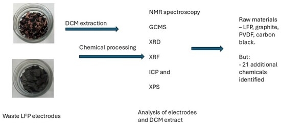
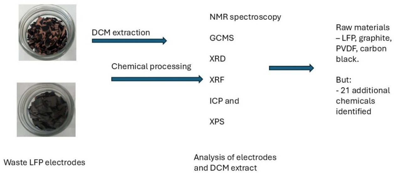
Graphical Abstract

1. Introduction

Renewable energy generation and storage play a key role as countries transition away from fossil fuels to address Net Zero Emissions (NZEs) targets [1,2,3,4,5]. Over the last decade, lithium-ion batteries (LIBs) have become ubiquitous in society, from consumer electronics, portable devices, and electric vehicles (EVs) to battery energy storage systems (BESSs) [6], both at the residential and industrial scales. Despite continued growth and demand for LIBs, less effort has been focused on what happens to the batteries at end-of-life (EoL) and how to best manage this increasing waste stockpile [7,8,9]. In recent years, governments have looked to further curb emissions (i.e., gas, liquid and solid waste) through the gradual implementation of environmental, social and governance (ESG) frameworks and circular economies. Here, sustainability, reduce, reuse and recycle strategies, and new green technologies have become connected to the renewable transition and other industrial sectors [10,11,12,13,14,15]. Developing cost-effective, low waste production and minimal environmental impact technologies has seen a change in how EoL technologies are viewed. Globally the vast quantities of LIBs that will be manufactured will need disposal at some stage and necessitates that as much of the LIB be repurposed (i.e., second life) [16,17], recycled, even upcycled [16,18] or downcycled in an effort to reduce the pressures of processing materials from virgin sources [19].
Currently, several recycling methods are used industrially to address manufacturing scraps and EoL LIBs. These consist of pyrometallurgy, hydrometallurgy and direct recycling [18,20]. Each has advantages and disadvantages, and with the introduction of the ESG framework, many of these technologies are looking to improve the efficacy of current processes or develop new technologies to meet stricter regulations around circularity, sustainability and eliminating the use of hazardous materials [19,21]. To complicate matters, the widespread global contamination of perfluoro/perfluoroalkyl substances (PFASs), commonly referred to as “forever chemicals,” has resulted in the European Union banning or minimizing the use of fluorinated chemicals [22,23]. Unfortunately, LIB manufacturers use PFASs, and the current concern is that the majority of spent batteries still end up in landfills [24]. It is clear that each country will have different challenges and opportunities to manage the growing waste of domestic spent LIBs through partial or full onshore recycling [14,25,26].
Recycling of LIBs is difficult compared to lead acid batteries, which, through significant introduction of regulations and standardization of cell formats (i.e., designed for recycling), have achieved global recycling rates >95% [27,28,29,30]. LIBs have become the predominant battery energy storage device, where the performance, lifetime, energy features, cost, size, weight and safety requirements are heavily dependent on the end-use application. Whilst some LIB chemistries have entered the market early (i.e., LFP and NMC predominant) [31], emerging technologies are changing the demands around the LIB chemistry now and into the future. In addition, solid-state lithium-ion, sodium-ion, lithium–sulfur and redox flow batteries (RFBs) are emerging alternatives to address the limitations of current commercial LIBs. Nevertheless, there are significant quantities of current commercial LIBs that will reach EoL that require recycling in the very near future [19,32].
To date, the core focus of linear recycling LIB technologies has been centered around recovery of critical metals, such as Li, Co and Ni [14,18,19,33,34]. However, there is a diverse range of inorganic and organic chemicals used in LIBs, some highly toxic, and others resource-intensive to produce; thus, it would be unethical environmentally and economically if they were not recovered and reused [35]. A recent study has compared the benefits of manufacturing LIBs from raw or recycled materials and found that using the latter source is expected to deliver a 58% cost-reduction benefit [36] as well as minimize the environmental impact as a result of the vast quantities of raw materials (i.e., new mining operations) needed. From the ESG compliance and circular recycling principles, the percent chemical composition of a typical LCO/graphite LIB [9] are shown to be cathode (31%), cathode aluminum collector (8%), anode (22%), anode copper collector (17%), electrolyte and additives (17%), separator (3%) and carbon black/binders (4%), highlighting the vast number of materials required [34]. Recently, there has been renewed interest to determine whether the organic electrolytes [35] used can be recycled [37,38,39,40] or even potentially upcycled [41,42], thereby reducing the waste footprint from current recycling processes. However, whether the spent organic solvent can be reused for batteries or secondary applications is dependent on what chemicals/impurities are present (toxic and non-hazardous), how easy they are to remove to meet end-use specifications and the overall cost of the process [43]. To date, there is limited information and few analytical methods reporting the contaminants present in waste LIBs prior to various chemical processing methods employed to recover various components. This is largely due to the scarcity of suitable EoL spent lithium-ion battery waste and the variety of industrial recycling methods used, compounded by the proprietary nature of chemicals employed by battery manufacturers and recent studies that involve processed samples from recyclers that have already undergone significant chemical processing (no information of the actual method provided) [8,17,37,38,39,40,41,44,45,46,47]. Understanding all the chemicals present in the initial waste LIBs would enable more greener, sustainable and circular recycling methods to be developed, to provide high purity materials required for battery manufacturing (i.e., battery grade > 99.99%) [19,48] and therefore allow recycled battery materials to support the ever-growing demand for next generation LIBs.

2. Materials and Methods

2.1. Chemical and Reagents

Anhydrous dichloromethane (DCM) (>99.8%, contains 40–150 ppm amylene as stabilizer) was used as supplied for the extraction of the cathode and anode.
The following chemicals were sourced from chemical suppliers and used as provided. Acetonitrile (Sigma Aldrich 99.8% anhydrous, St. Louis, MO, USA), chlorobenzene (Sigma Aldrich 99.8% anhydrous), cyclohexylbenzene (TCI Japan, >97%, Tokyo, Japan), diethyl carbonate (Alfa Aesar 99%, Ward Hill, MA, USA), dimethoxyethane (Sigma Aldrich 99.% anhydrous, inhibitor free), dimethyl carbonate (Sigma Aldrich 99%), ethanol (Merck absolute for analysis, Rahway, NJ, USA), ethyl carbonate (Sigma Aldrich 98%), ethyl methyl carbonate (Sigma Aldrich 99%), fluorobenzene (Sigma Aldrich 99%), fluoroethylene carbonate (Sigma Aldrich 99% anhydrous), methanol (Merck Liquid chromatography grade), propylene carbonate (Sigma Aldrich 99.7% anhydrous), and vinylene carbonate (Combi-Blocks 98%, San Diego, CA, USA) were used as is for NMR and GCMS studies. Experimental procedures for preparing and analyzing samples are described in the Supplementary Materials following the literature and methods developed as a part of this paper [49,50,51,52,53,54,55,56].

2.2. Characterization Instrumentation and Sampling Methodology

Sample preparation and instrument parameters used for NMR, GCMS, XRD, XRF, ICP and XPS are described in detail in the Supplementary Materials document.

3. Results and Discussion

The challenges of recycling of LFP are well documented in reviews [57,58,59,60,61,62] and it is encouraging to see some publications considering circularity and sustainability [45,46,48,63], but significantly more progress needs to be made in the waste management of all the chemicals used. For hydrometallurgy or direct recycling, shredding of the spent LIB can be undertaken under inert gas, vacuum or atmospheric conditions [64]. The first two are used as a safety measure to minimize the initiation of fires and it also allows for isolation of water and air-sensitive species (i.e., LiPF6), whereas the latter is cheaper and shreds are typically deposited directly into water baths, readily decomposing reactive species, quenching possible fires, minimizing the release of particulate matter/volatiles (e.g., hydrofluoric acid) and dissolving water-soluble materials. Both have advantages and disadvantages and are heavily dependent on the chemistry, structure and state-of-health of the LIB at EoL [16]. However, dismantling of the cell under inert atmosphere offers a novel insight into the state of the battery electrolyte, chemical additives used and degree of degradation, before hydrolysis and further external degradation occurs during the typical recycling process.
EoL LFP cells were provided by a commercial supplier without any information about the history of the battery. The LFP cell was dismantled in a glovebox under an inert atmosphere to minimize the exposure of air-sensitive materials to oxygen and water, then separated into the cathode and anode substrates, which were then cut into pieces approximately 10 × 10 mm. These smaller pieces are easier to handle and have greater surface area, allowing for better extraction of the DCM-soluble materials from the electrodes.
Given the diverse range of chemicals that can be used in LIBs [35], we have taken a holistic approach by applying a range of chemical processing and analytical techniques to gather as much information as to the chemical composition of electrolyte at EoL. This approach is commonly used in synthesis of chemicals to qualitatively identify the chemicals present in the initial crude sample prior to determining what chemical processing pathways are best suited to recover the target compounds from waste byproducts in high yield and purity. Before extraction of the electrode material, to highlight the difference between raw materials and processed components used by battery manufacturers, commercial chemicals used in the cathode, anode and electrolyte/additives were characterized by different techniques, such as nuclear magnetic resonance (NMR), gas chromatography mass spectrometry (GCMS), X-ray diffraction (XRD), X-ray fluorescence (XRF), Inductively Coupled Plasma (ICP) and X-ray photoelectron spectroscopy (XPS) to provide an insight into known and novel proprietary chemicals used by LIB manufacturers. More formal information beyond battery cell chemistries (e.g., LFP, NMC, LCO) is of critical relevance to LIB-recycling activities and to the development of sustainable and cost-effective solutions for managing the increasing volume of waste LIBs. Electrode materials were analyzed to assess compositional differences between the cathode and anode, both prior to and following the DCM solvent extraction process.

3.1. Characterization of Raw Materials Used in LIBs: Cathode, Anode, Electrolyte Solvents and Other Novel Chemicals

3.1.1. Nuclear Magnetic Resonance (NMR) Spectroscopy and Chemical Stability

LIB cells are typically manufactured under conditions where water and oxygen are at extremely low levels (i.e., ppm) as some chemicals are reactive and produce unwanted byproducts. NMR spectroscopy allows several nuclei to be studied in a non-destructive fashion, providing rapid feedback about chemical composition.
Samples were subjected to a variety of NMR experiments using a range of nuclei (H, C, and F) to examine the different chemicals typically found in LIB cells as electrolyte solvents/additives and to assist in the identification of “unknown additives” that are proprietary chemicals used by battery manufacturers. Reference chemicals including diethyl carbonate (DEC), dimethyl carbonate (DMC), ethylene carbonate (EC), fluoroethylene carbonate (FEC), propylene carbonate (PC), and vinylene carbonate (VC) were analyzed in deuterated DCM (d-DCM) (see Supplementary Materials Figure S1a–m).
Lithium hexafluorophosphate, which is the preferred commercial salt used with carbonate solvents to enhance the electrochemical conductivity of the electrolyte, is known to be oxygen and water sensitive [50,65]. We observed that deuterated dimethyl sulfoxide (d-DMSO) (see Supplementary Materials Figure S1n) was the best solvent to determine the presence of LiPF6 using 19F NMR spectroscopy instead of d-DCM, which yielded no detectable signal. To minimize decomposition of LiPF6 whilst handling the electrodes and electrolyte outside of the glovebox, we found minimal exposure time to the atmosphere sufficient to undertake characterization by NMR and other techniques. This is supported by qualitative studies of the reactivity of LiPF6 under laboratory conditions reported here (see Supplementary Materials Table S1). The 19F NMR spectrum for LiPF6 is a doublet indicating the F atom is magnetic, coupled to 31P nuclei. The 1H NMR of certain fluorinated compounds are also typically complex as H-F coupling produces unique and complex splitting patterns as observed for additive FEC (see Supplementary Materials Figure S1g). NMR spectroscopy serves as a practical tool when coupled with other analytical methods described in this paper to assist in identifying what chemicals might be present in the spent electrolyte.

3.1.2. Gas Chromatography Mass Spectrometry (GCMS) Analysis of Chemical Standards

Solvents commonly used as electrolytes in LIBs are typically linear and cyclic organic carbonates [35,66,67]. Recent work by Scholl and coworkers [37] used GCMS to examine a range of carbonate solvents, other chemicals found as additives and degradation products (detected >106 chemicals, of which 42 were unknowns) in semi-processed (methodology not mentioned) spent battery electrolyte from waste nickel–manganese–cobalt (NMC) LIBs.
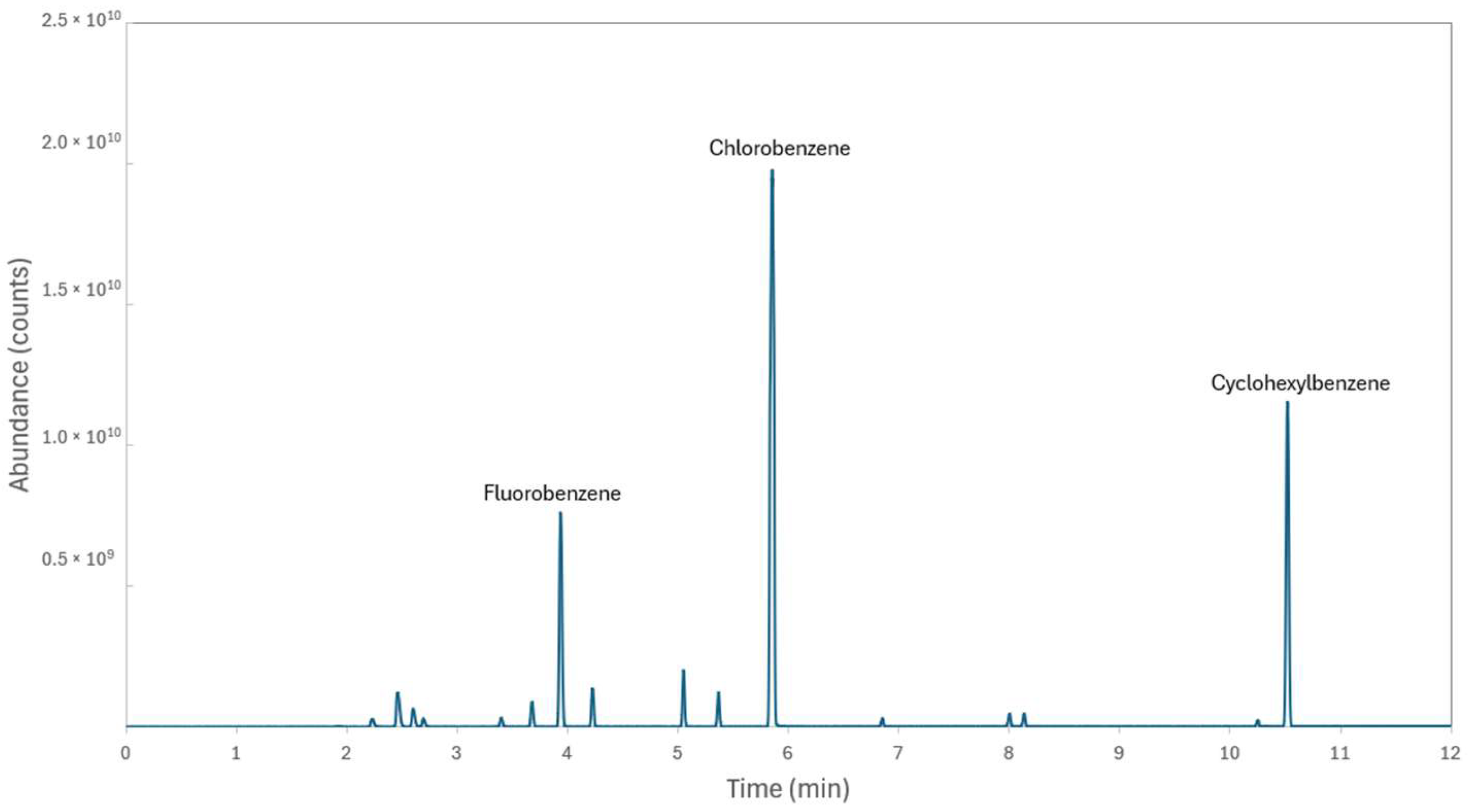
A selection of reference chemicals was characterized by GCMS (Figure 1). A standard solution of acetonitrile (ACN), chlorobenzene (CB), cyclohexylbenzene (CHB), diethyl carbonate (DEC), dimethoxymethane (DME), dimethyl carbonate (DMC), ethanol (EtOH), ethylene carbonate (EC), ethyl methyl carbonate (EMC), fluorobenzene (FB), fluoroethylene carbonate (FEC), methanol (MeOH), propylene carbonate (PC), and vinylene carbonate (VC) was prepared for analysis. The standard solution was characterized by GCMS to determine retention times and purity and collect mass spectral data for comparison to key compounds of interest (see Supplementary Materials Table S2). These chemicals have boiling points ranging from 65 °C (MeOH) up to 242 °C (PC).

3.1.3. X-Ray Diffraction (XRD) of LIB Raw Materials

XRD can detect phases that are present in a crystalline form. Penetration depth varies depending on X-ray wavelength and sample composition, but for the current source and samples, it ranges from ~8 microns for LFP to ~340 microns for the graphite and carbon black samples. Detection sensitivity varies substantially between phases, but the minimum detectable amount is generally ~1%. Commercial raw materials, LFP, carbon black, graphite and PVDF, were used to obtain characterization data from different analytical techniques as they are commonly used in LIB electrodes.
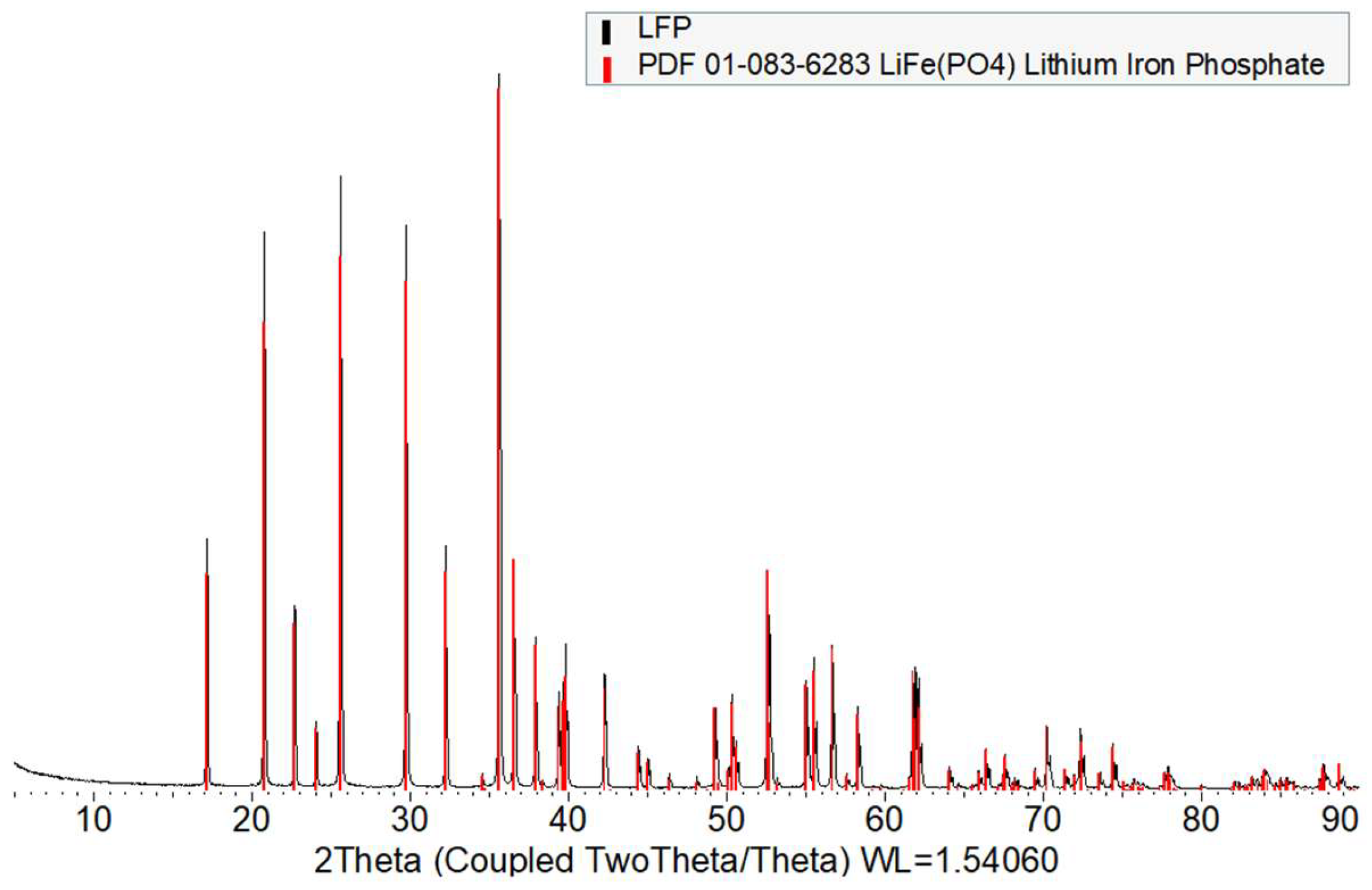
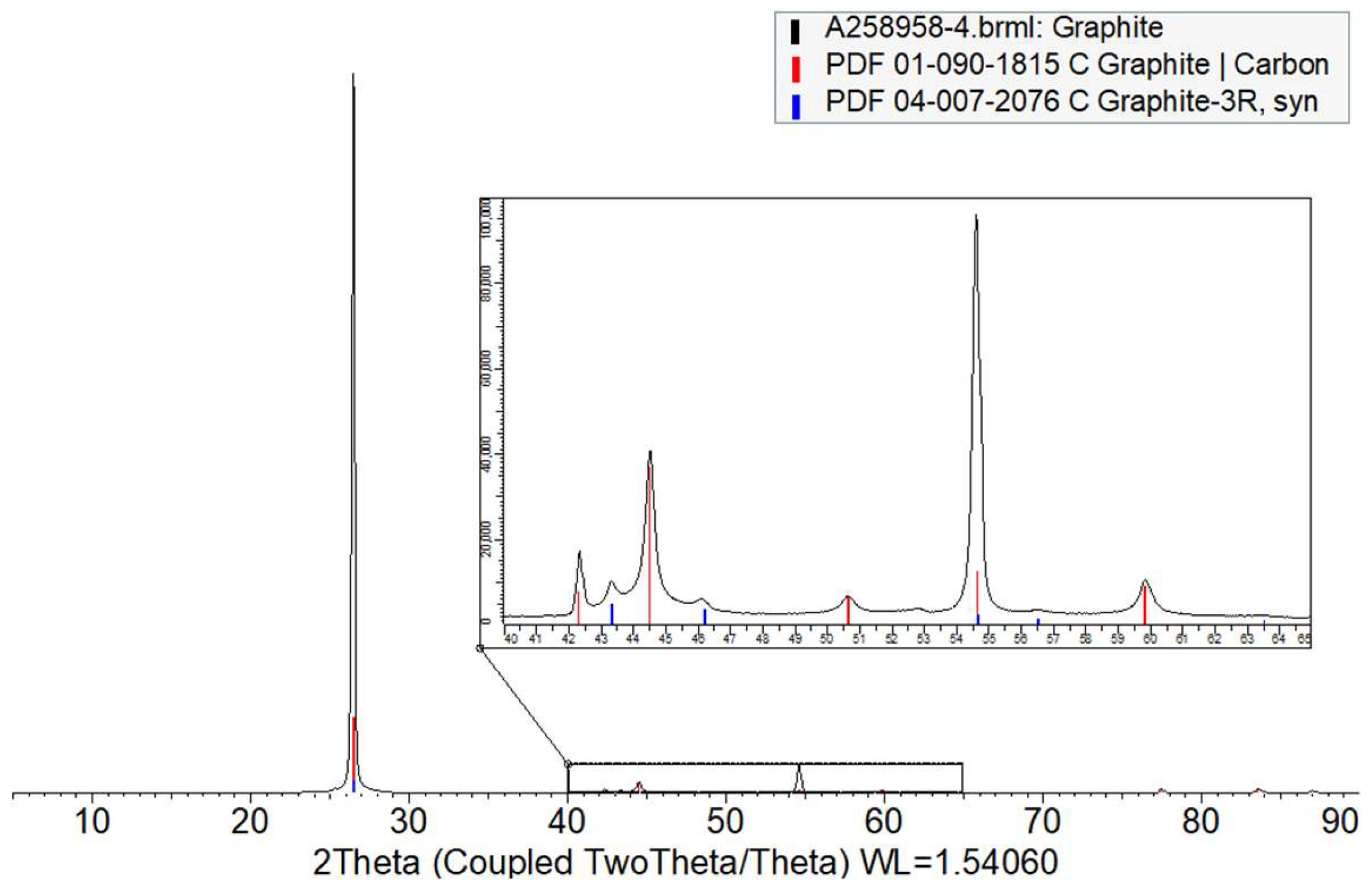
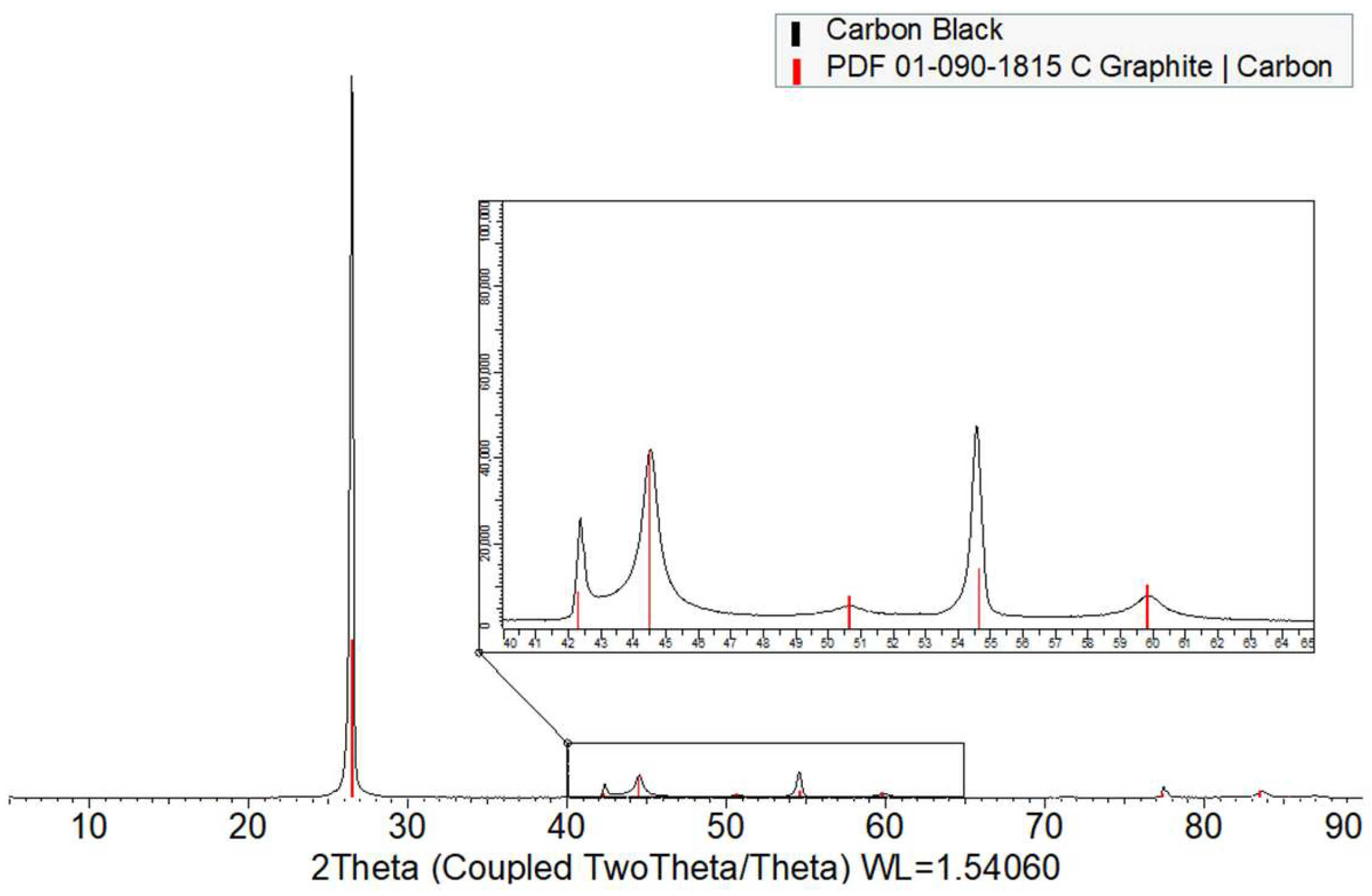
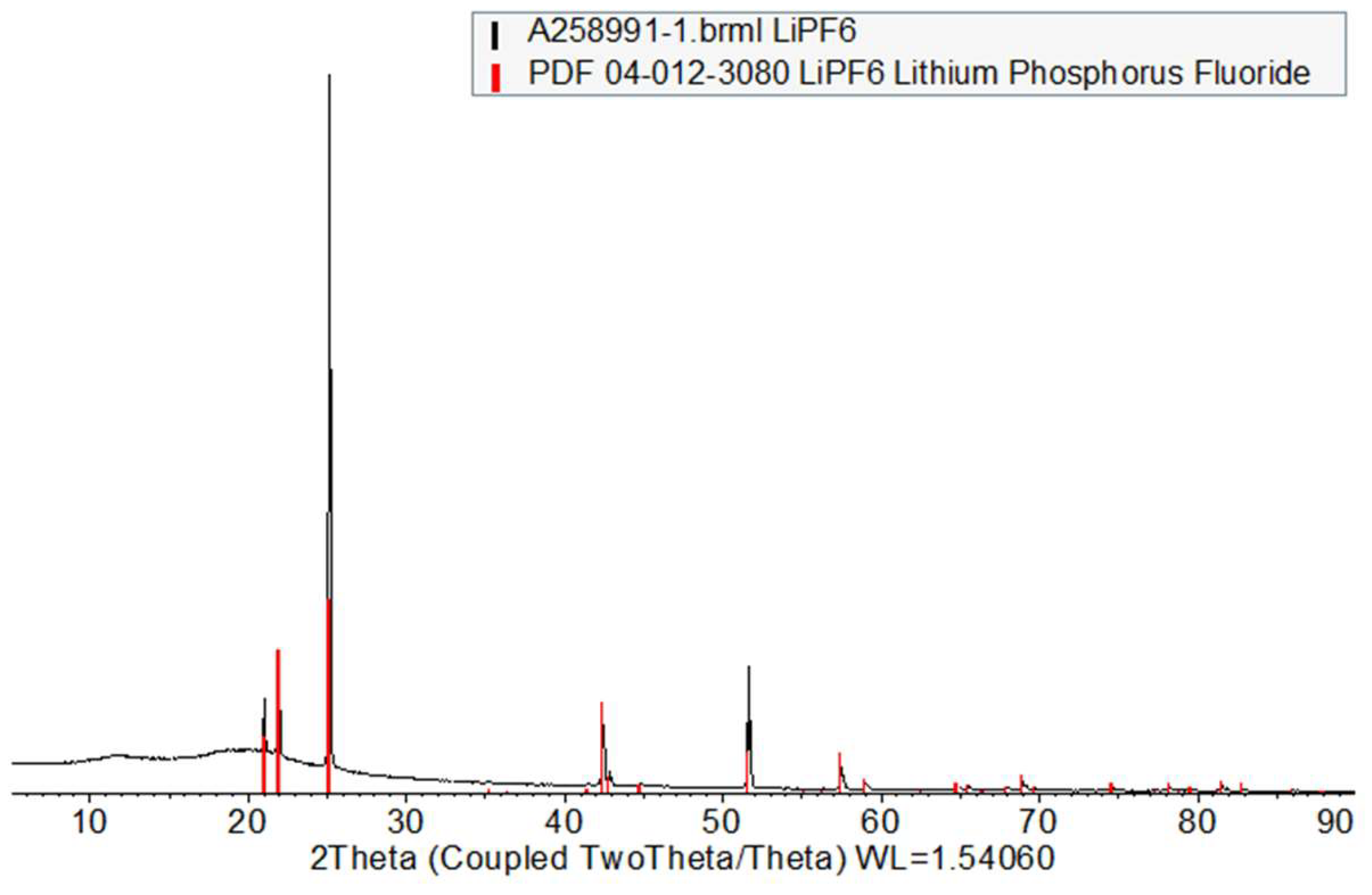
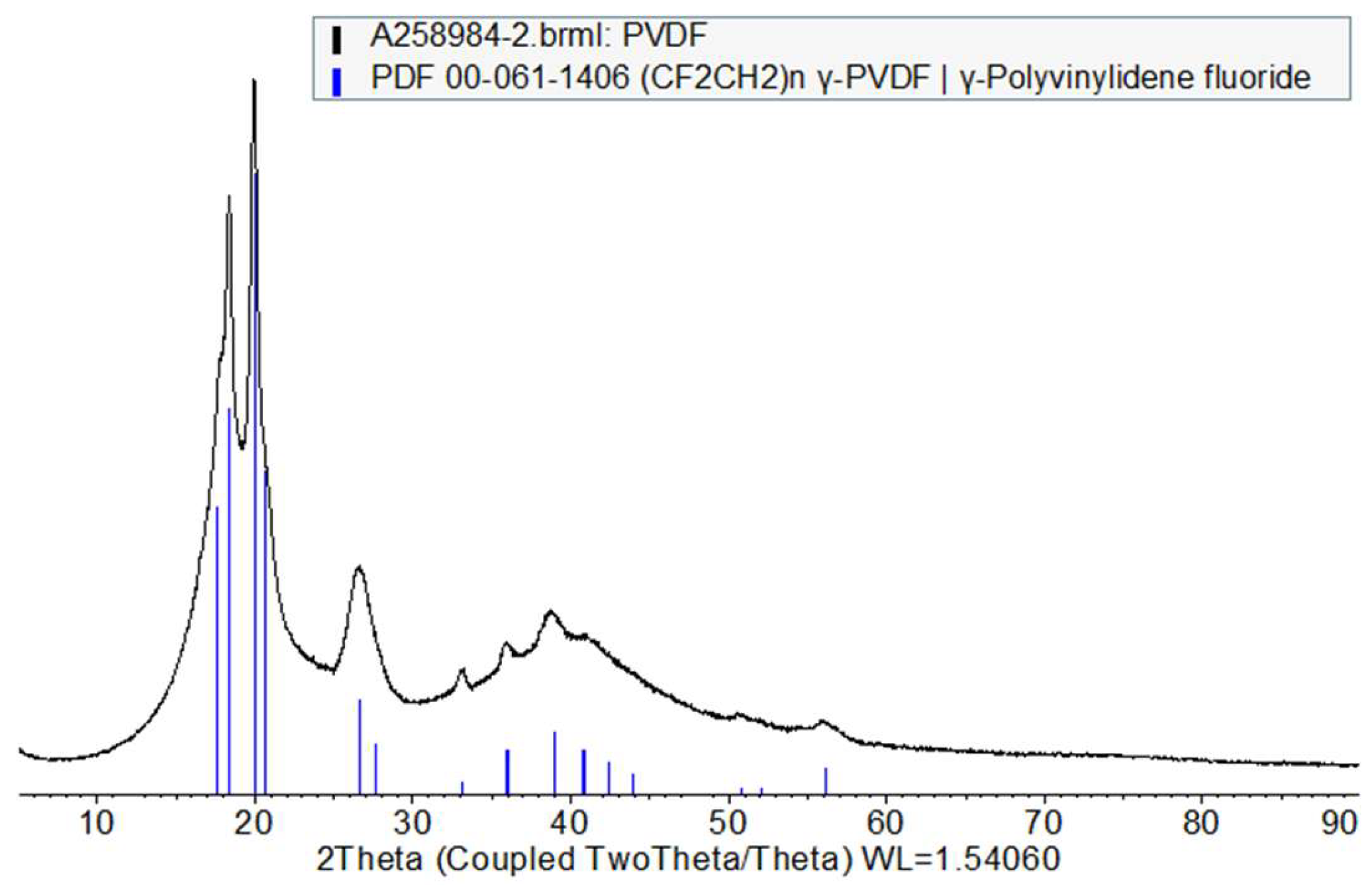
Phases found in the diffractograms are listed in Table 1, Table 2, Table 3, Table 4 and Table 5, alongside wt% values where possible. The 5–90°2θ region from the standard diffractograms collected from these samples are shown in Figure 2, Figure 3, Figure 4, Figure 5 and Figure 6.
The diffractogram collected from the LFP sample only exhibited peaks consistent with orthorhombic LiFePO4 (see Table 1 and Figure 2) [68]. Those peaks were consistent with reference data from card 01-083-6283 from the Joint Committee on Powder Diffraction Standards database (JCPDS) [51].
The graphite sample appears to comprise a mixture of the 2H and 3R polytypes reported in JCPDS cards (01-090-1815 and 04-007-2076) [51] and the literature [2,69], respectively, with the 2H polytype predominating. A trace peak was also found at ~14.6°2θ in the diffractogram collected from the graphite sample (see Table 2 and Figure 3), but this could not be defined.
Interestingly, the carbon black sample (see Table 3 and Figure 4) appears to be primarily composed of crystalline graphite in the 2H polytype (JCPDS card 01-090-1815) [51], whereas we would have expected mainly amorphous material.
The X-ray diffractogram collected from the LiPF6 sample shows that only one phase is present (JCPDS card 04-012-3080) [51] as seen in Table 4 and Figure 5 and consistent with the literature [70]. The broad background humps in the data collected from the LiPF6 sample are due to the dome under which the sample was placed during data collection.
The diffractogram obtained from the PVDF sample showed mainly amorphous content, alongside crystalline features, which could be matched to the gamma phase of PVDF (Table 5 and Figure 6), consistent with reference data from the JCPDS database (card 00-061-1406) [51] and the literature [71].

3.1.4. X-Ray Fluorescence (XRF) Spectroscopy of LIB Raw Materials

XRF can detect elements that may be present in forms not readily detected by XRD. For example, phases present in a non-crystalline form or in a semi-crystalline form in smaller quantities may not result in distinct peaks that can be detected by XRD.
XRF analysis was undertaken on the same raw materials (LFP, carbon black, graphite and PVDF) used in the XRD and XPS sections. Analyses were performed under atmospheric conditions (i.e., not equipped with a vacuum chamber) and therefore low atomic number elements (such as H, Li, C, O, F, and P) cannot be reliably detected. This includes almost all expected elements in the raw materials; however, it does allow for the detection of trace materials containing other elements of the periodic table, especially the presence heavy elemental impurities.
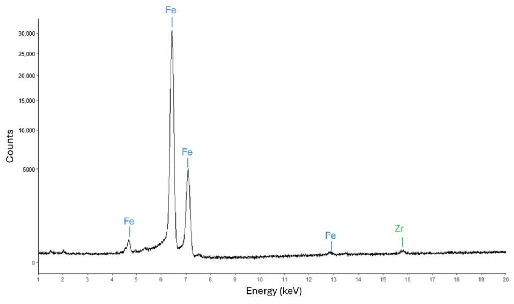
For LFP, in addition to the expected Fe peaks, a low amount of Zr impurity is present (Figure 7). For both the PVDF and carbon black samples, no signals were detected (see Supplementary Materials Figure S4a,b), whereas there was a trace amount of nickel (Ni) present that we assume originates from the underlying sample holder (see Supplementary Materials Figure S4c).
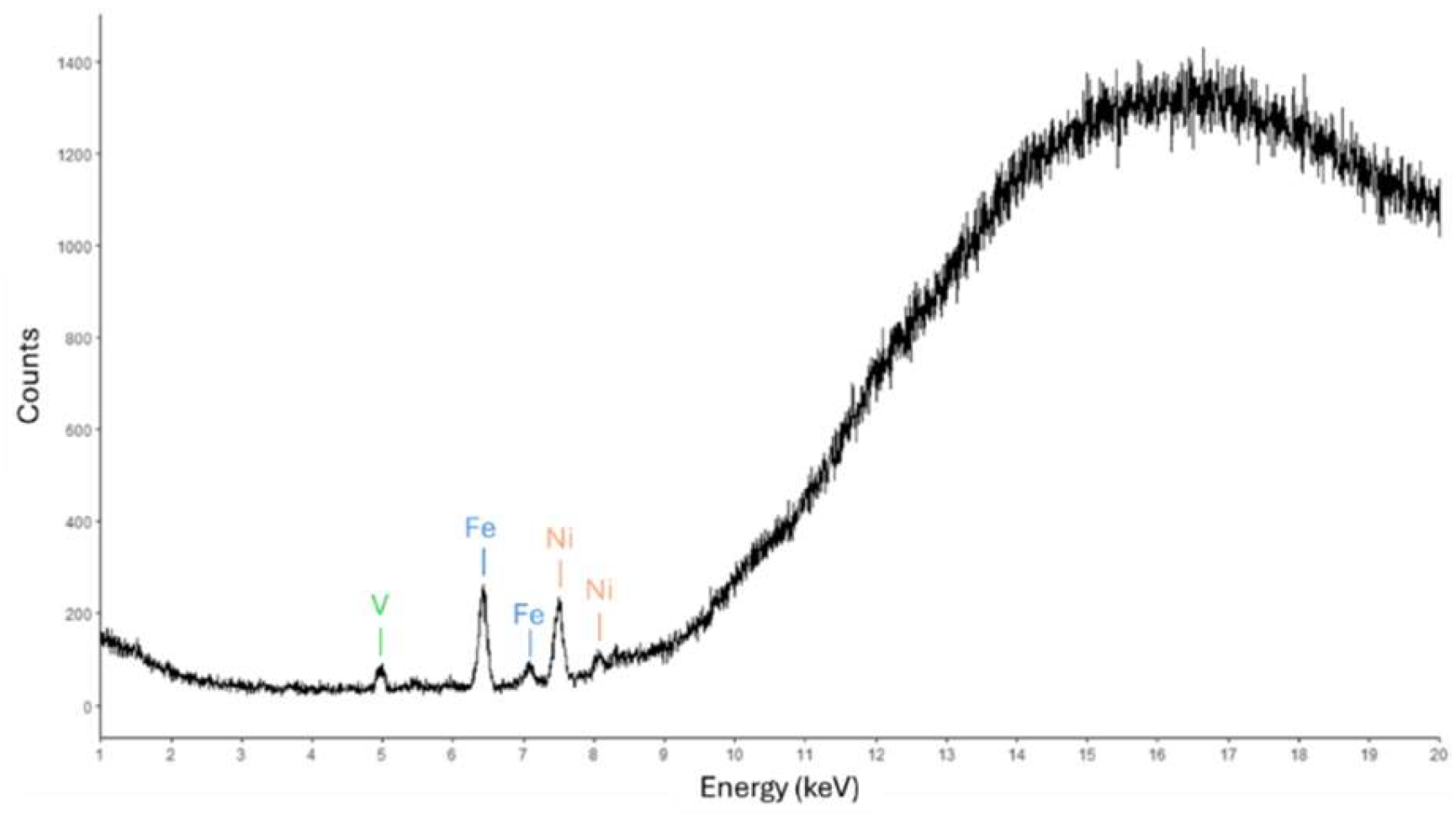
For graphite (Figure 8), the unexpected presence of iron (Fe) and vanadium (V) peaks were observed, suggesting the presence of a low amount of Fe and V impurities. It is unclear where these materials originate from (see section on ICP later).

3.1.5. X-Ray Photoelectron Spectroscopy (XPS) of LIB Raw Materials

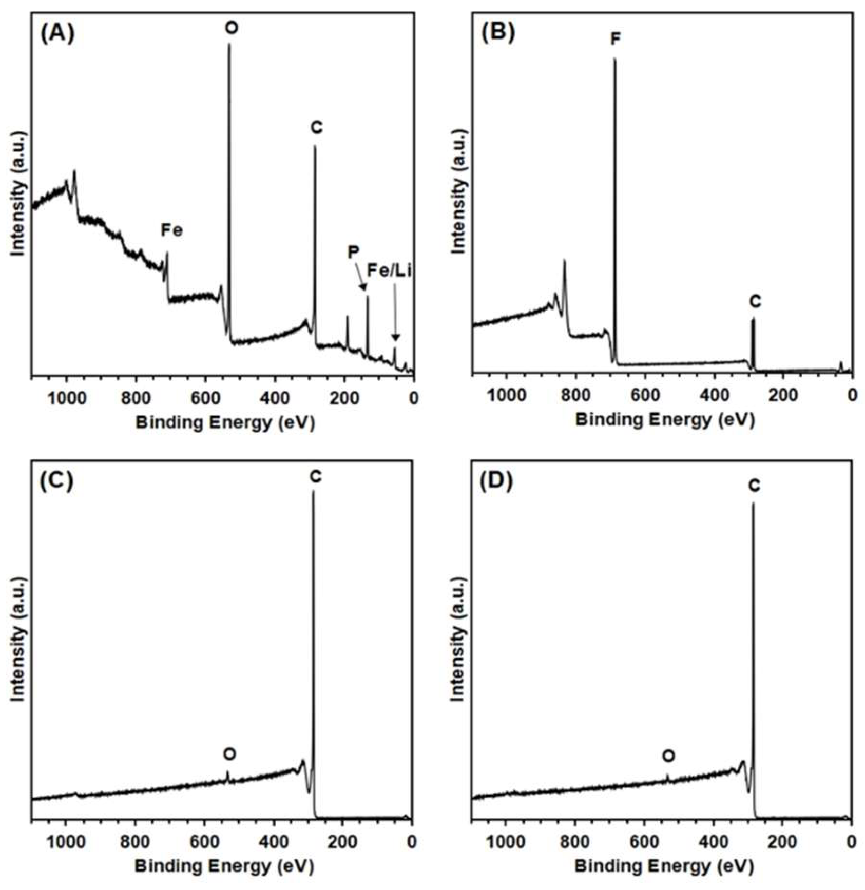
XPS is a surface-sensitive technique that typically probes < 10 nm of the surface of a material. The same battery raw chemicals, LFP, PVDF, carbon black and graphite, were analyzed by XPS (Figure 9).
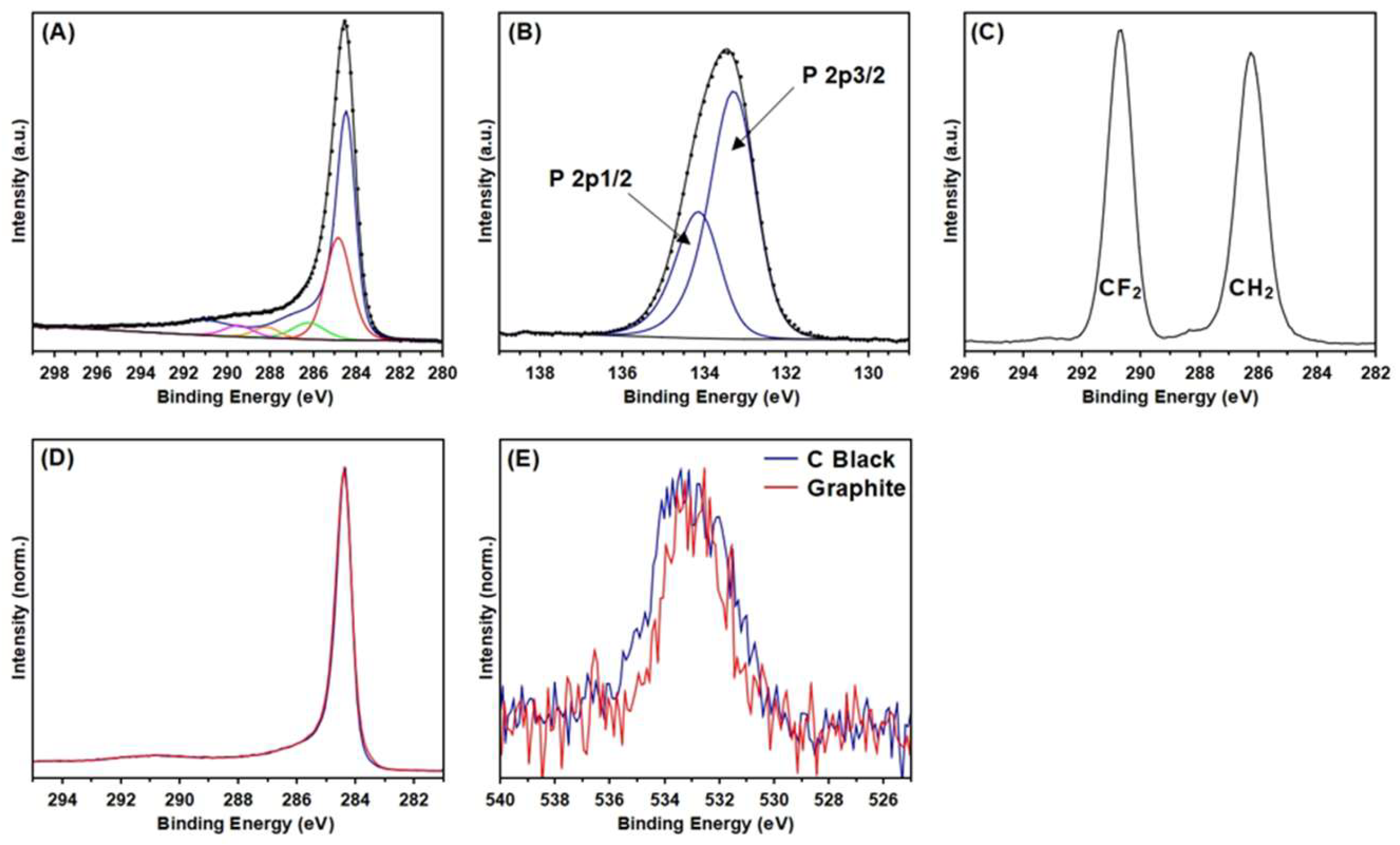
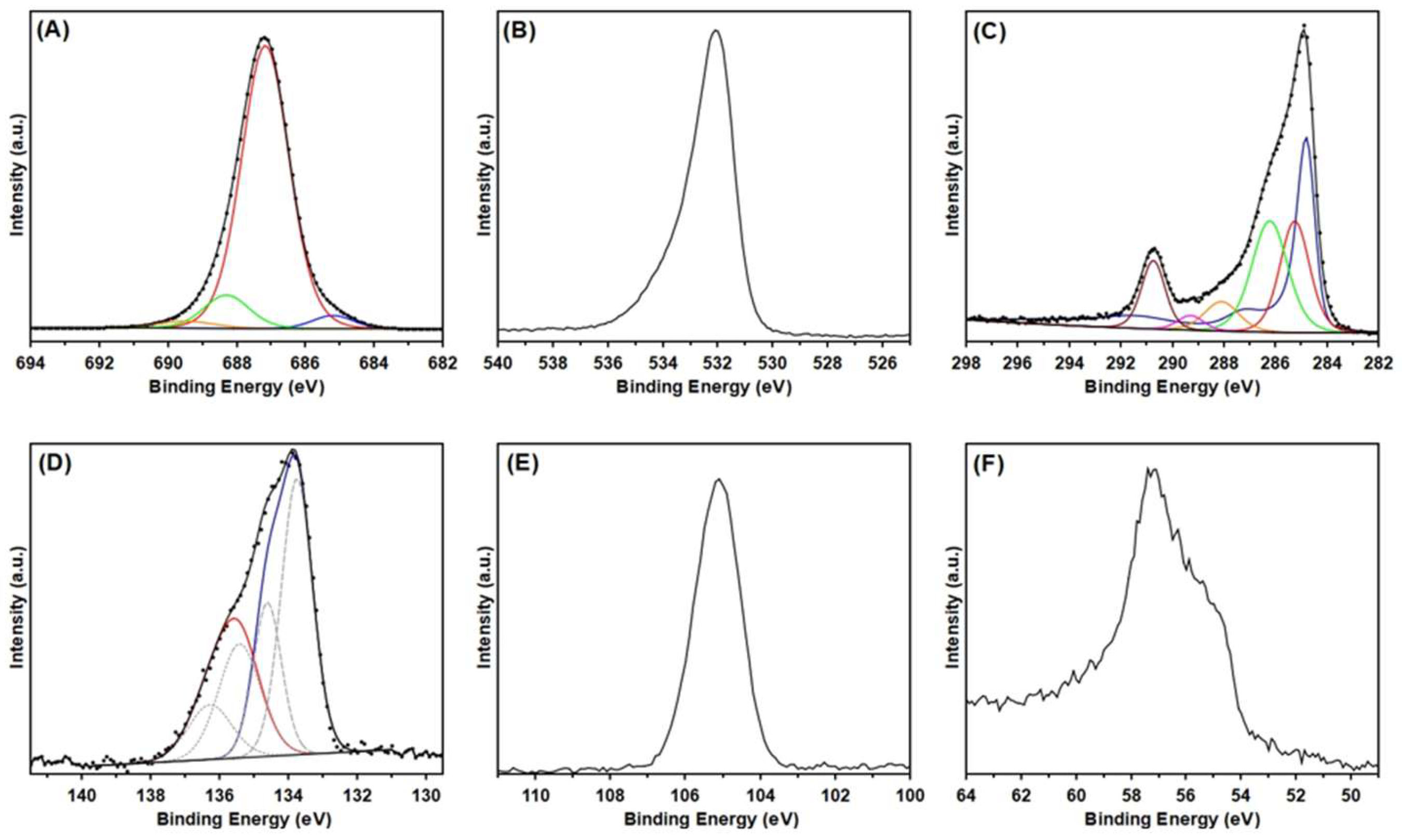
LFP was shown to contain Li, Fe, P, O and C. The LFP C 1s spectrum appeared graphitic though noticeably broadened (Figure 10A) which has been observed in other LiFePO4 systems [72,73]. Fitting the spectrum with a synthetic graphitic model adapted from [74], it was shown that in addition to graphitic signal, aliphatic hydrocarbons and various CO functionalizations were also present.
Fitting the P 2p spectrum showed that the binding energy (BE) position for the main intensity is consistent with the results observed for phosphate in FePO4 dihydrate (Sigma-Aldrich) by this lab and the reported values for phosphate (Figure 10B) [72,75]. Due to the complexity of the system, the Fe 2p spectrum was not fitted (Supplementary Materials Figure S5a).
The PVDF contained only C and F and the C 1s spectrum showed two main peaks corresponding to CH2 and CF2 (see Figure 10C). Comparison of the C1 and valence band region (Supplementary Materials Figure S5b) to a reference database confirmed the material was PVDF [76].
Carbon black and graphite only contained C and a minor amount of O (<2 At.% for carbon black and <1 At.% for graphite). When the corresponding C 1s were compared (see Figure 10D), carbon black and graphite were almost indistinguishable despite the expected differences due to crystal structuring/ordering The position of the O 1s peak for both materials was consistent with organic O (see Figure 10E) [77].

3.1.6. Extraction of LIB Materials from Cathode and Anode Electrodes: Findings from NMR Spectroscopy Analysis

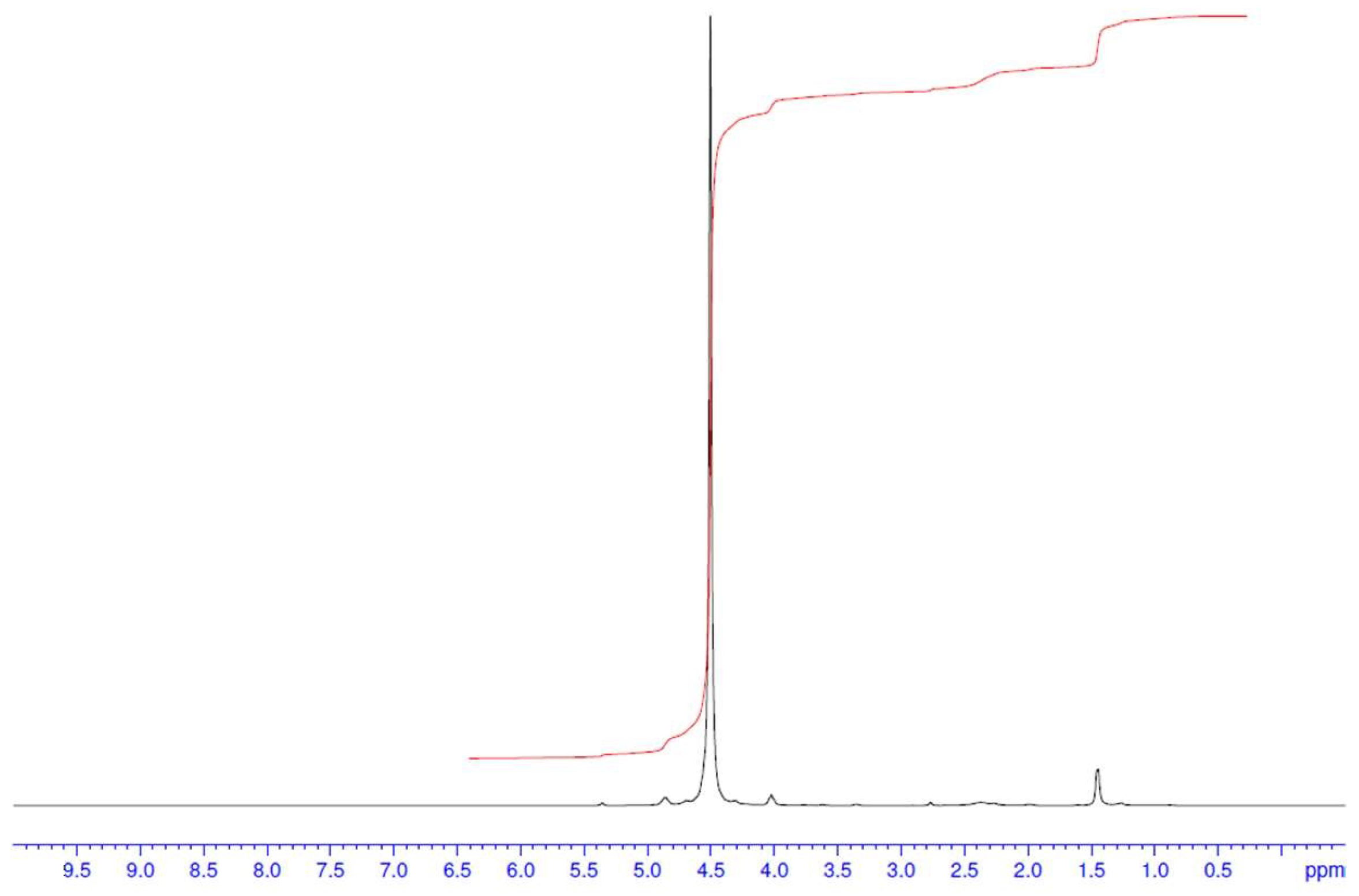
Both cathode and anode samples were subjected to separate Soxhlet Extraction processes using anhydrous DCM under a nitrogen atmosphere over a 24 h period. Once the mixture was cooled the DCM solvent was removed to afford the cathode- and anode-extracted materials as crude brown oily solids. Unlike the electrolyte samples characterized by Scholl and coworkers [37] that contained only trace amounts of battery carbonate solvents, indicative of some prior chemical processing by the recycler, analysis by 1H NMR spectroscopy (Figure 11) revealed broad signals in both electrode samples, attributable to primarily ethylene carbonate (EC) and minor contribution of propylene carbonate (PC) cosolvent (based on our 1H and 13C NMR standards; see Supplementary Materials Figures S1e (EC) and S1j (PC), respectively), and other trace materials. Analysis of the 19F NMR spectrum (see Supplementary Materials Figure S6a) indicates mainly LiPF6 at ~−80 ppm (as a doublet which agrees with our standard (see Supplementary Materials Figure S1n)), another major fluorinated product and a minor product. These other fluorinated products have different chemical shifts to LiPF6, occurring at ~−140 (minor) and −150 (major) ppm, and occur as singlets indicating they are not coupled to the phosphorus or hydrogen nuclei. Analysis by 19F NMR of some known salt additives typically reported in battery solvents (lithium fluorosulfonamide (LiFSI), lithium bis(trifluorosulfonamide) (LiTFSI) and LiBF4) resulted in a match for LiBF4 for the other major −150 ppm signal.
This result was consistent with the spectrum obtained from a reference sample prepared using material sourced from a commercial supplier (see Supplementary Materials Figure S1o). Unfortunately, we could not identify the minor fluorinated product or other trace materials by NMR spectroscopy as the large amounts of EC, PC, LIPF6 and LiBF4 obscured their signals.

3.1.7. Analysis of DCM Extracts of Cathode and Anode After Water Processing: Bulk Chemicals from NMR Spectroscopy Analysis

The bulk carbonate solvents and fluorinated salts found in the initial DCM electrode extracts were reduced in quantity by an aqueous treatment. However, it should be noted that some chemicals, degradation products and impurities that are ionic in nature, reactive to water (e.g., LiPF6 and LiBF4) or highly water-soluble (e.g., compounds with water solubilizing groups) will likely be removed from these DCM residues and therefore not be available for detection by GCMS. It should be noted that some compounds will not be detected by GCMS analysis, as these compounds are unsuitable for this technique (i.e., LiPF6, LiBF4 and other non-volatile materials).
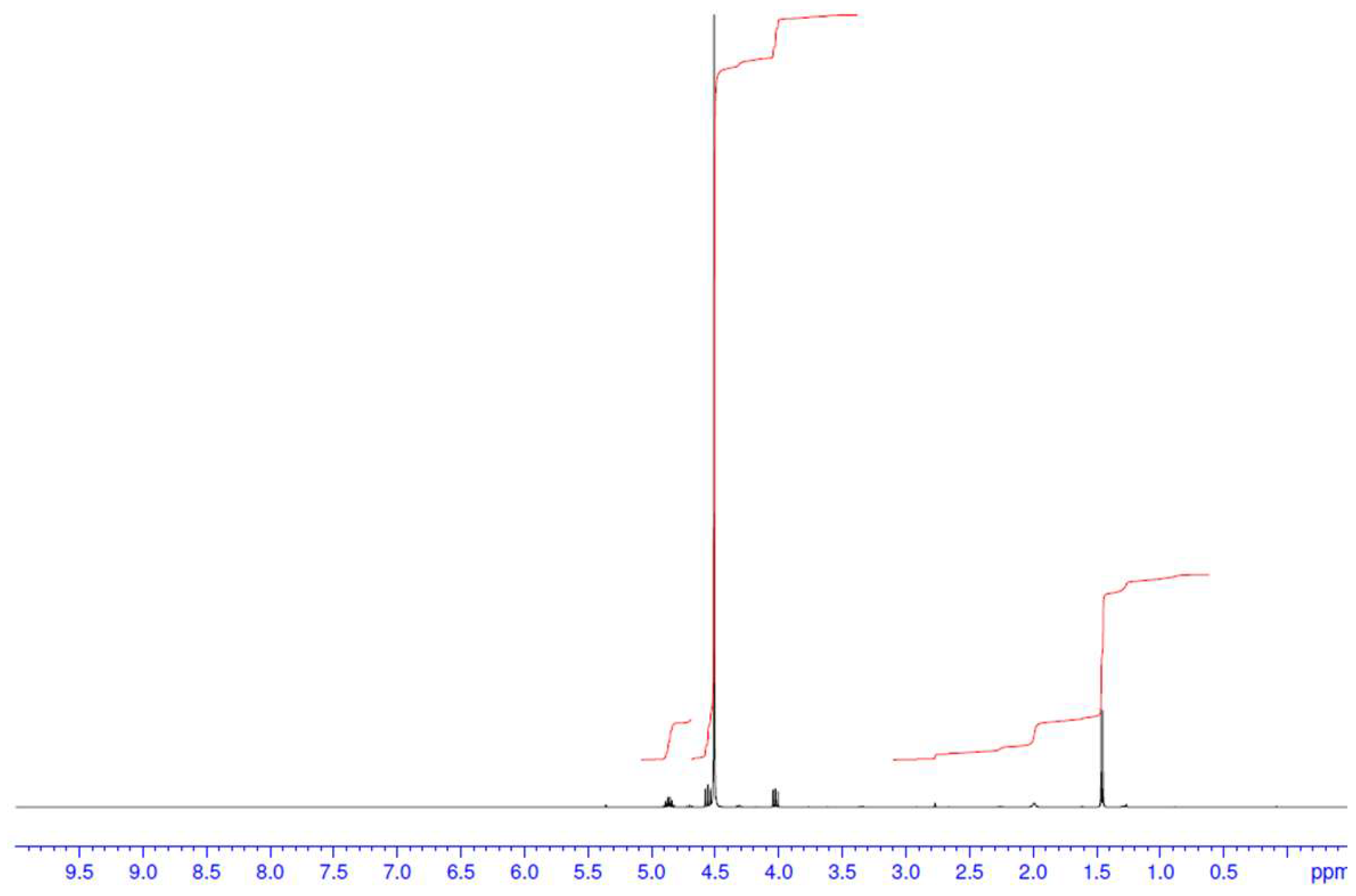
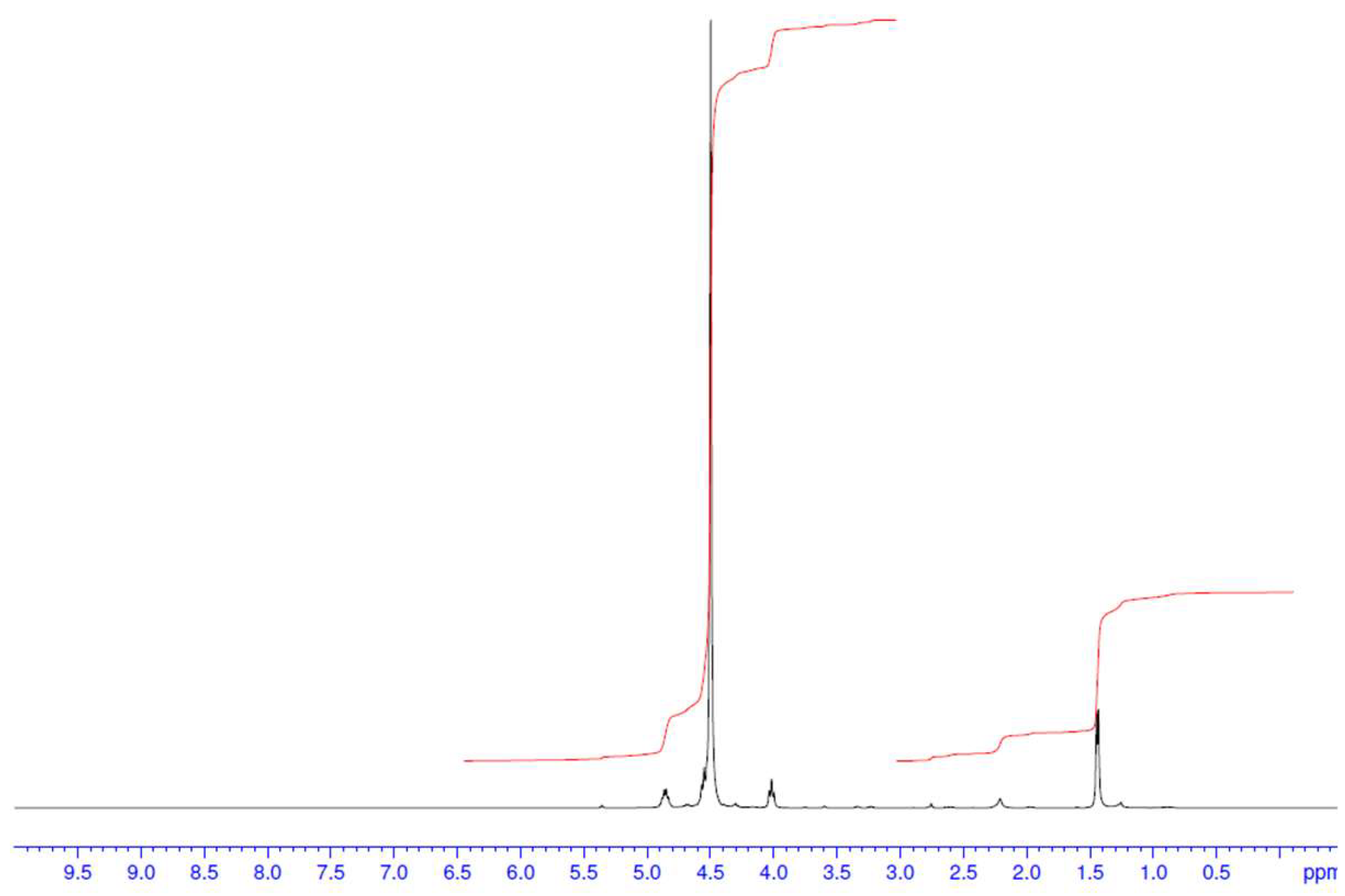
Analysis of the 1H NMR spectra for the cathode and anode show that after the aqueous workup, the signals have become significantly sharper and have less carbonate solvents (Figure 12 and Figure 13) compared to previously (Figure 11), making the trace chemicals (see Section 3.1.6) and also the 13C and 19F spectra more noticeable (Supplementary Materials Figure S7a,b).
Analysis of the 13C and 19F NMR spectra further support what was observed in the 1H NMR spectrum. In the 13C NMR spectrum, signals due to impurities are now more prominent than in the initial DCM extracts. In the original 19F NMR spectrum, signals at ~−60 ppm (LiPF6), ~140 ppm (unknown) and ~150 ppm (LiBF4) are no longer observed. Whilst we expect LiPF6 and LiBF4 to react with water to produce water-soluble byproducts, we were surprised to see the unknown fluorochemical signal disappear, indicating high water solubility.
Some impurities were present in both the cathode and anode samples, although the anode exhibited several distinct signals not observed in the cathode. However, given the number of signals and differences in intensity, it suggests a variety of impurities are present and these cannot be easily identified by NMR spectroscopy; therefore, GCMS was pursued.

3.1.8. Findings from GCMS Analysis of Water-Processed DCM Electrolyte Extract: Identification of Chemical Additives

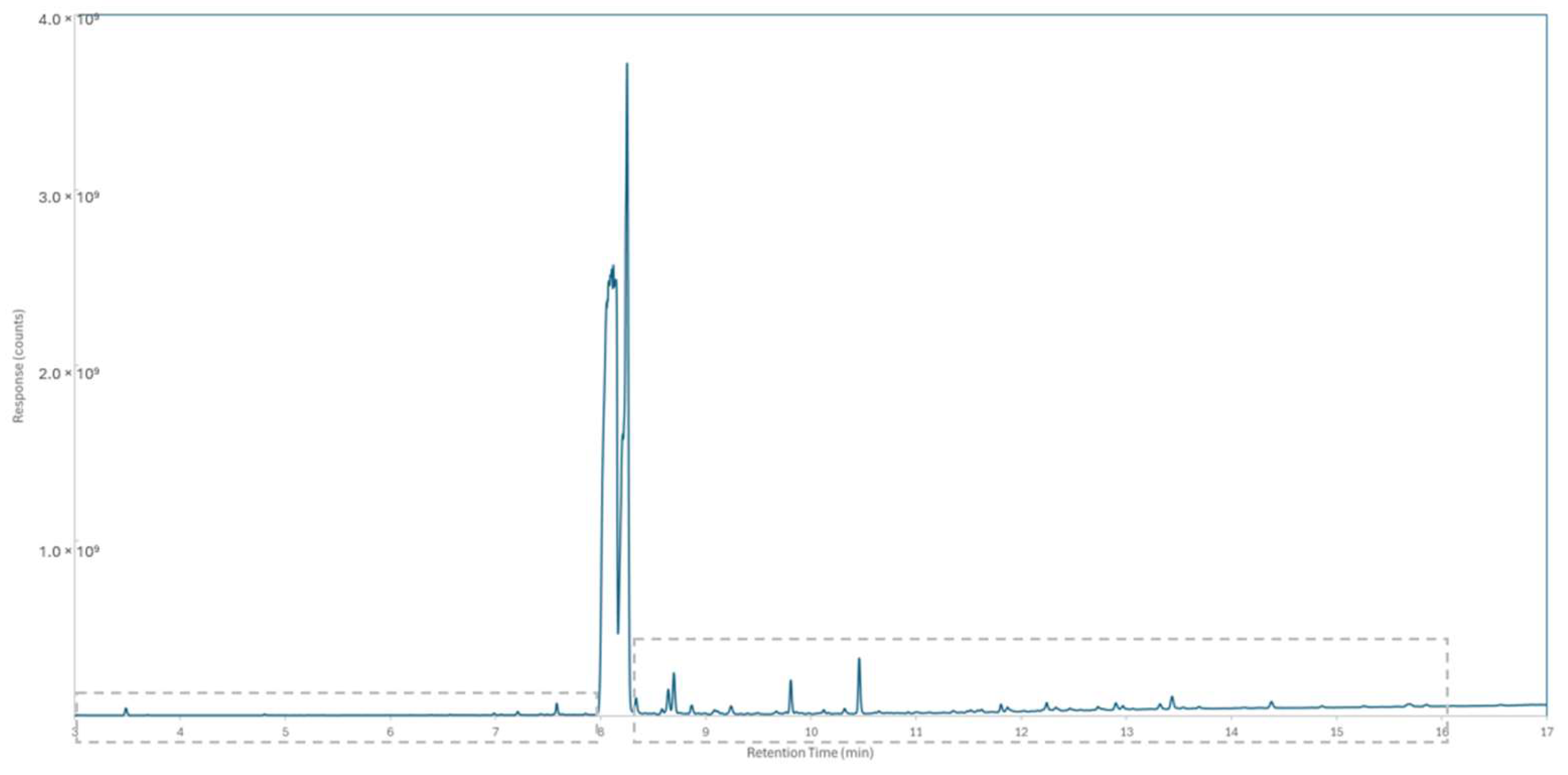
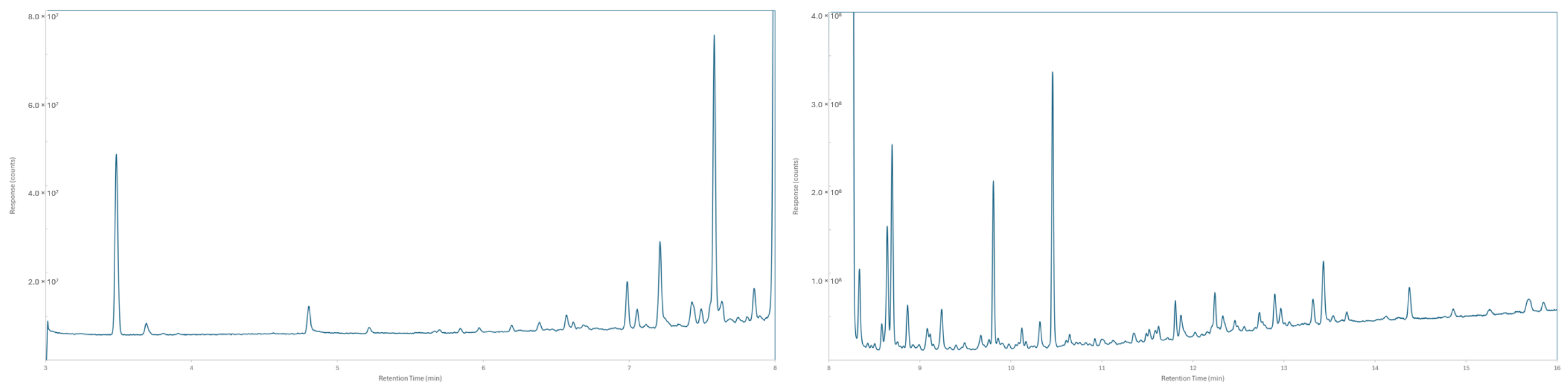
The GCMS spectra of both the water-processed electrode DCM extracts show that the signals of the carbonate solvents have been dramatically reduced, allowing for the signals of the impurities to become more visible (Figure 14 and Figure 15). As with the proton NMR spectra, we observe compounds of similar retention time (RT) in both the GCMS traces for the cathode and anode, while some signals were exclusive to the anode extract, indicating unique chemical interactions occurring at this electrode with the unique electrolyte/additives [35] used by the battery manufacturer, likely for SEI formation. Detailed GCMS was undertaken on the anode DCM extract.
Electron ionization (EI) and chemical ionization (CI) mass spectral data were collected for the electrode extract. Chromatographic peaks were background subtracted to obtain clean mass spectra, and in the first instance searched against the NIST [56] mass spectral databases for possible matches. Plausible library matches were returned for eight of the peaks in the chromatogram (see summary in Table 6 and full data in Supplementary Materials Table S8). Accurate masses (<5 ppm) of EI fragments were used to support the assignment of proposed structures to the peaks in the chromatogram. Using methane reagent gas, CI mass spectra were also collected with the molecular formula determined from the accurate masses (<2 ppm) of protonated adducts [M + H]+, and confirmed with [M + C2H5]+ in most cases. For some peaks, insufficient or not high enough quality data were collected to determine the molecular weight/formula or structure. However, in these cases we have proposed likely sub-structures gleaned from the available mass spectral data. As a reminder, GCMS is only able to detect compounds that are volatile and not suited for certain materials. Based on the GCMS analysis undertaken and methodology used (see Supplementary Materials Sections S2.0 and S8.0), a range of chemicals were detected and categorized as known to be used, likely to be used, or unusual and unknown compounds.
Using NMR spectroscopy on the spent electrolyte from each electrode and analysis of the DCM extract by GCMS, we can conclude at least 26 chemicals are present. NMR revealed the carbonate solvents, primarily ethylene carbonate (EC) with a minor amount of propylene carbonate (PC), and electrolyte salts, LiPF6 and LiBF4, plus an unknown fluorinated material. Analysis of the DCM extract of the electrode by GCMS enabled the identification of a further 21 distinct chemical species.
Of the remaining 21 chemicals detected by GCMS, entries 1, 2, 4, 6, 7, 8, 11, 12, 13, 14, 19 and 20 are found in both the cathode and anode, while entries 3, 5 and 21 are only found in the anode. It is well known that chemical additives are used in the formation of chemical electrolyte interface (CEI) and solid electrolyte interface (SEI) layers found on the cathode and anode, respectively [78]. Also, from these 21 chemicals detected, three chemicals—acetylformate (entry 14), propane-1,3-sultone (entry 13) and an unknown chemical (entry 12)—were found in significant amounts as highlighted by their signal intensities. Propane-1,3-sultone is well known to be used in batteries as an additive as it forms a SEI layer on the anode, preventing exfoliation of graphite, and it has been shown to reduce gas production at both electrodes [79]. Also, degradation products from LiPF6 are well studied and are heavily dependent on the other chemical additives used, but likely explain the presence of entries 3, 4, 6, and 18 [50].
Six chemicals, entries 7, 8, 9, 11, 20 and 21, are present in moderate amounts while 12 chemicals, entries 1–6, 10, and 15–19, are present in trace amounts. Entries 1–5, 7–9, 11, and 15–16 were identified by matching retention time and mass spectral data against the standard to unequivocally confirm the peak identity or matched against a mass spectral library entry at a high correlation. The molecular formula could be matched with the experimentally determined accurate mass-to-charge ratio value with a maximum error of 5 ppm. Unfortunately, nine entries, 6, 10, 12, and 17–21, had insufficient data to assign a molecular formula and structure, and therefore are defined as unknown.
While some chemicals (entries 2, 3, 4, 5, 6, 7, 8, 10, 14, and 16) might be expected to be used as a cosolvent and additive or arise as a degradation product, entries 1, 9, 11, and 15 are not commonly known to be used in batteries; again, this highlights the array of proprietary chemicals that battery manufacturers use which may cause contamination issues in the recovery and recycling of all battery chemicals.

3.1.9. Findings from Inductively Coupled Plasma–Optical Emission Spectroscopy (ICP-OES): Analysis of Cathode, Anode and DCM Extract Before and After Water Processing: Metal Migration

The elemental composition was obtained for the pre-treated electrodes (cathode and anode), the residue obtained from the DCM extraction of post-treated electrodes (cathode and anode), and the post-treated electrodes (cathode and anode), with key data shown below (Table 7) and the full data in Supplementary Materials Table S9. The information gleaned from this analysis supports and explains some of the features observed in the other analytical techniques used in this article, with some unexpected findings.
The observation from the ICP results is the ease with which the metal ions are easily extracted during the DCM process, unexpected given their highly ionic nature. However, transition metal dissolution, migration and deposition at the anode is well documented for a host of cathode materials [80]. Analysis of the cathode pre-treatment shows significant levels of Al, Cu, Fe, Li, P and V, but analysis after the DCM treatment shows that the levels of these elements dramatically decrease in the cathode. A closer examination of the DCM extract indicated higher amounts of Al, Cu, Fe, Li, P and V present in this sample, which suggests that the organic materials present are complexing with these metal cations, allowing them to be solubilized in the organic DCM phase. These findings also agree with the ICP chemical and XRF analysis of LFP black mass by Ravnsbaek and coworkers [8], where, in addition to Fe, P, Al and Cu, they observed traces of Si, Zr, Rh and B (see our XRF section later as well), but could not determine the origin of the source.
The increased solubilization of metal ions in aqueous and organic solvent is well documented to be enhanced by the use of simple commercial chemicals or designer ligands (i.e., monodentate, bidentate, tridentate, etc.) [81,82,83] with certain organic functional groups [82,84,85,86]. It is highly likely that the chemical additives and degradation fragments found in the spent LFP waste electrolyte easily complex with metal ions, extracting them from the electrodes over time, leading to a decrease in battery SoH. This would suggest significant degradation of the LFP electrode has occurred, and the mechanical structure of the cathode has significantly deteriorated, making these metal ions accessible. Likewise, a closer examination of the pre- and post-treated anode also reveals that there is a dramatic reduction in the concentration of Cu after treatment with DCM, whereas very high levels of Cu are found in the DCM extract.
In contrast, the level of B found in both the post-treated anode and cathode is slightly higher than the pre-treated cathode and anode, with minimal amounts being extracted from the DCM process. This would indicate that the B element, determined as LiBF4 (from the NMR section), unlike LiPF6, shows strong binding with electrode materials and is less easily extracted using the DCM process. The DCM extraction process therefore removes a significant amount of other material from both electrodes and thus enriches the electrode in B content.
In the initial DCM extraction process, analysis of crude material by 1H NMR shows signals that are noticeably broad, but after water treatment the signals are much sharper in the spectrum. The origin of this feature can be ascribed to the unexpected presence of paramagnetic metal ion species (i.e., Al Cu and Fe), which, when subjected to a water process, are removed.
The presence of V is observed by ICP in all samples, but specifically in the pre-treated cathode. Although it was detected during analysis of the raw battery material (only graphite) when using XRF, the manufacturer of this cell could use suppliers where vanadium is present and could explain the significant amount of V. Interestingly, there are reports of doping LFP to improve battery performance with a variety of metal species including V [87,88], or it could originate from the sourcing of raw materials where graphite deposits have been co-located with vanadium [89].
A significant amount of Cu is detected on the anode, which is expected as the graphite is coated onto a Cu current collector. However, we were surprised to see a significant amount of Cu in the DCM extract and cathode. Likewise, Al was observed in high quantities in the cathode where it is used as a current collector, but Al was also detected in moderate quantities in the DCM extract and trace amounts in the anode. Crossover of these the metals from the current collectors to the alternative electrode may be indicative that this LFP battery has a very poor SoH, therefore necessitating recycling rather than second-life applications [16]; it may not even be suitable for direct recycling methods.
Analysis of the different samples for Li content reveals that the bulk of the material is found in the pre-treated cathode and DCM extract of the cathode. This would indicate that the presence of Li in these samples is a result of LFP and LiPF6 chemicals.

3.1.10. Analysis of the Pre-Treated and Post-Treated Spent LFP Cathode and Anode:

Findings from XRD Analysis of Pre- and Post-Treatment of Cathode
Both the pre- and post-treatment cathode sample diffractograms (see Supplementary Materials Table S10a,b and Figure S10a,b) looked largely alike, both being dominated by LiFePO4 with trace sharp peaks that could be indicative of the presence of a tiny amount of LiH. As per the raw samples, the LiFePO4 peaks in the diffractogram were consistent with reference data from card (01-083-6283) [51] from the JCPDS database.
The only significant difference between the cathode samples was the presence of minor copper in the diffractogram collected from the post-treatment cathode.
Findings from XRD Analysis of Pre- and Post-Treatment of Anode
No differences could be observed between the pre- and post-treatment anode samples (Table S10c and Figure S10c). Both diffractograms comprised peaks indicative of copper metal [90] (JCPDS card 04-006-2601) [51] and highly oriented graphite for which the 2H polytype was used as a reference, although the preferred orientation meant that these peaks could have equally been assigned to the 3R polytype, and no crystallinity or phase-balance differences were observable.
Findings from XRF Analysis of Pre-Treated Cathode
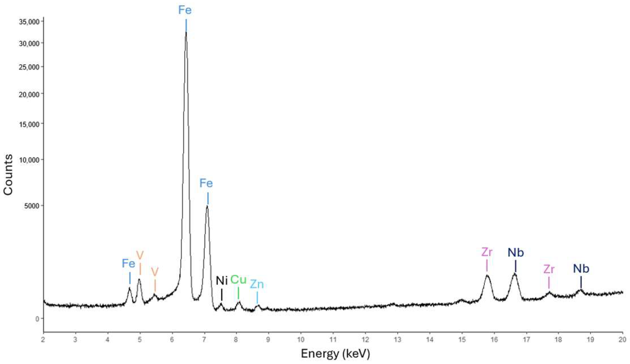
Figure 16 shows the XRF spectrum from the cathode pre-treatment. In addition to the expected Fe peaks, peaks associated with V, Cu, Zn, Zr, and Niobium (Nb) were present. Note that the y-axis is on a square root scale, which was necessary as all unexpected elements were present in low amounts.
The ICP analysis did not detect the Zr and Nb found in the XRF data as the standard assay does not include platinum group metals, rare earth elements, mercury, thorium and uranium as these metals require a mass spectral scan in addition to ICP analysis. This suggests that XRF might be a suitable method to detect elements not routinely run by ICP, especially as these were not expected to be present. More importantly, there has been a review showing that over the past 20 years, various studies have been undertaken on the doping of LFP with various metal species in an effort to improve LIB performance [91].
Findings from XRF Analysis of Pre-Treated Anode
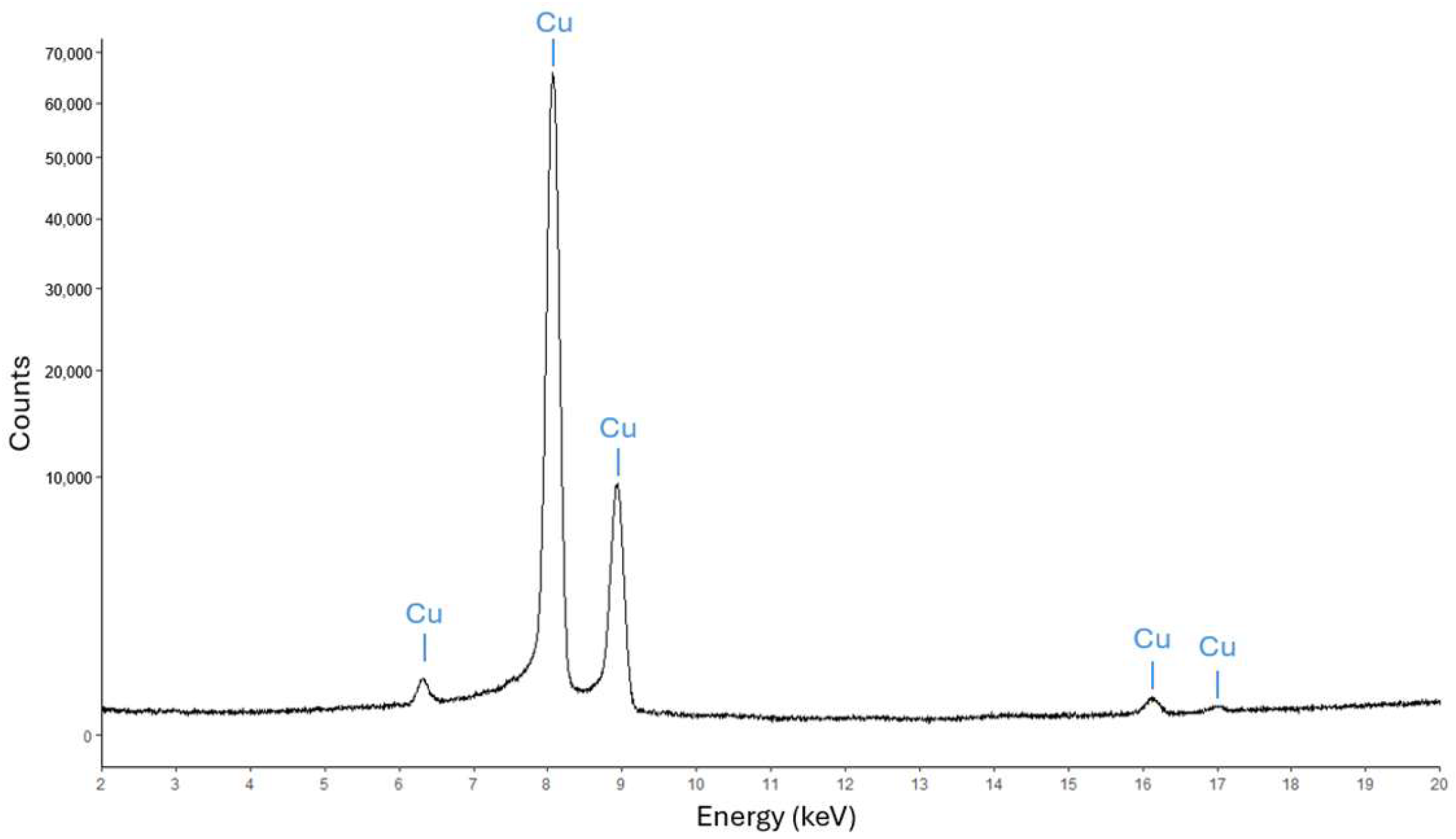
Figure 17 of the anode prior to DCM extraction shows a significantly different spectra from the pre-treated cathode with only Cu peaks from the substrate present. No other substantial information could be gleaned from this spectrum.
Findings from XRF Analysis of Post-Treatment of Cathode and Anode
The same spectrum of the cathode post-treatment (see Supplementary Materials Figure S10e) shows no change in the elements present to that of the cathode pre-treatment spectrum (Figure 16). This indicates that these Fe, V, Cu, Zn, Zr, and Nb species are not in a form easily extracted with DCM compared to these metals found in the ICP analysis for the electrolyte (i.e., see Table S9; high Cu, Fe and V in cathode and high Cu in anode). However, an increase in the intensity of the Cu peak was observed. This suggests Cu may be present in a transportable form. For the anode post-treatment spectrum (see Supplementary Materials Figure S10f), no significant difference was observed, suggesting the changes to the chemicals on this surface could not be detected by XRF technique and the materials are not labile.
Findings from XPS Analysis of Pre- and Post-Treatment of Electrodes
Due to the presence of volatile organic compounds and the need for XPS sample loading and data acquisition to be undertaken under high vacuum (i.e., 10−9 Torr), the pre-treated cathode and anode could not be analyzed using this technique as various compounds would be removed from the electrode surface during the preparation process.
Findings from XPS Analysis of Post-Treatment Cathode
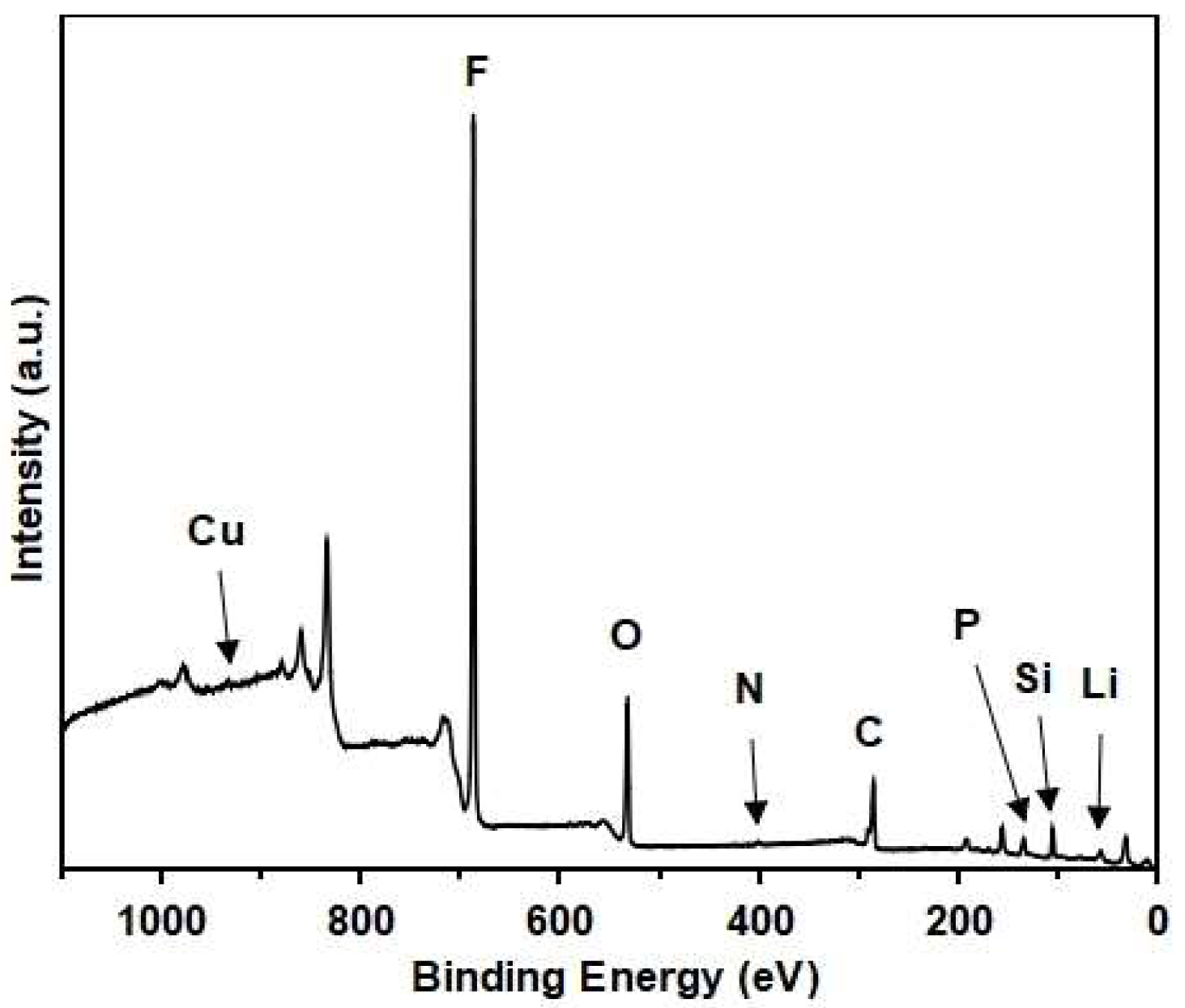
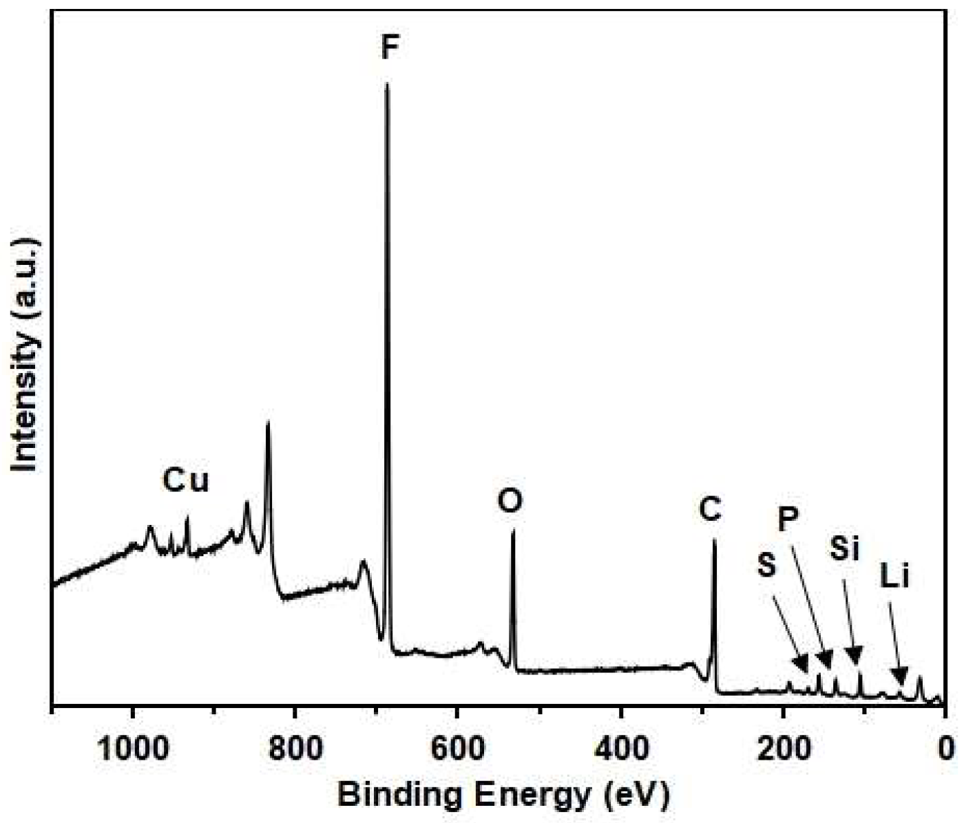
The post-treatment cathode material was analyzed by XPS to investigate the chemicals present on the surface of the electrode to complement the other techniques used to determine chemical composition. The XPS survey spectra revealed a complex mixture of elements (Figure 18) with a composition that was predominantly F with Li, P, O, C, N, Si, S, and Cu also present. Note that the size of the signal is not a reflection of the amount present as different nuclei have different sensitivities when using XPS. Interestingly, Fe was not detected on the cathode surface although it is observed to be present in the XRD (pre- and post-treatment cathode analysis). While the high F content would mask weak Fe 2p signal, other Fe core-level peaks and the Auger signal would not be affected. Given these signals were not observed, Fe does not appear to be present in the thin surface layer analyzed by XPS at the nm thickness, suggesting that a coating of material on the surface may be present.
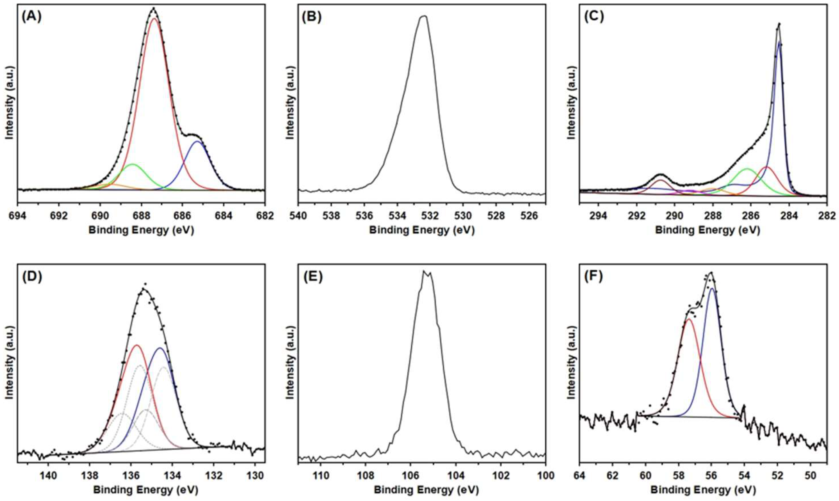
To elucidate the chemical species present, core-level spectra were analyzed (Figure 19). The C 1s spectrum was fitted using the synthetic graphitic model mentioned earlier and showed graphitic carbon, aliphatic hydrocarbon, CO functionalization and CF2 signal. There also appears to be carbonate present, which may result from the degradation of carbonate solvents. The F 1s showed a minor peak at low BE, indicative of LiF, but the main peak is more difficult to define. Based on the C 1s spectrum, the peaks at high BE appear to be organofluorines. Looking at the P 2p region, two states were fitted with the high BE state, presumed to be PF6 based on the literature [92] and the reference material analyzed. Based on the reference material and the literature [73,75], the lower BE doublet is phosphate. The low P content means that PF6 alone cannot account for F signal. Looking at the Si 2p region, the unusually high BE of the Si peak suggests that Si is bonded to F. However, analysis by XRF, XRD and ICP does not indicate any significant levels of Si. This suggests that there may be a very thin film of degraded Si-based residue as a part of the CEI. It is known that silane materials are added as scavenging agents for water and to enhance surface wettability of the electrode. The Li spectra support the presence of a carbonate with the signal at low BE. It is also likely that LiF is present, and that possibly Li is associated with PF6 based on the high BE of the main Li intensity.
Findings from XPS Analysis of Post-Treatment of Anode
Analysis of the post-treatment anode material yielded similar results to the cathode. Like the cathode, the XPS survey spectra revealed F was the most prominent element in the surface composition with Li, P, O, C, N, Si, S, and Cu also detected (Figure 20). No Fe was detected on the anode surface, which agrees with the XRD and XRF data.
The core-level spectra were analyzed to further discern the chemical species present (Figure 21). The C 1s spectra was fitted using the same graphitic model as previous figures and showed similar graphitic carbons, aliphatic hydrocarbon and CO functionalization. The peak at high BE is typical of CF2. Comparing this with the F 1s region, these could be organofluorines, either PVDF and/or PTFE. The F 1s region shows a clear peak at low BE which is likely LiF. Comparison with the Li 1s region supports this. The primary peak in the F 1s is suspected to be a mix of mainly PF6 anion and some SiFx. The Li 1s region had an additional signal at high BE that was in the report range for LiPF6 and the P 2p region shows two states with one in the range of PF6 anion and the Si 2p peak which sits at an unusually high BE as seen in the cathode. The second P state did not appear to be phosphate as observed for the cathode and it is proposed to be either a metaphosphate and/or fluorophosphate, which are both consistent with chemicals identified in the GCMS [73,93,94].

4. Conclusions

Given the growing quantities of LIBs being used globally, recycling of all battery chemicals is becoming an important aspect of addressing sustainability, circularity and emerging global regulations. LIBs use a host of materials, some critical materials, and others highly toxic, which necessitates their recovery and recycling or upcycling at EoL. A key challenge is developing recycling processes that are green, economically and environmentally viable, and use sustainable materials to enable significant reductions in the substantial energy and chemical inputs required by current linear recycling technologies. To achieve greater efficiency and sustainability towards recovering as much of the chemicals used in LIBs, we have developed a simple chemical process (Soxhlet Extraction) and analytical protocols (NMR, GCMS, XRD, ICP, XRF and XPS) to study the types of contaminants found in spent LIB electrolytes and electrodes. The methodology presented reveals the presence of >26 chemicals, including known chemicals, likely proprietary materials used by battery manufacturers [9,34,35], degradation products and several unidentified substances. By using different chemical processing and a combination of analytical techniques, we identify chemicals which are inorganic, non-volatile, volatile, and air- and water-sensitive. NMR spectroscopy determined the presence of solvents (ethylene and propylene carbonates), salt additives (LiPF6 and LiBF4) and an unknown fluorochemical. Refinement of the DCM extract allowed trace chemicals to be enhanced; however, some chemicals were no longer present, indicating high water solubility (i.e., carbonate solvents, LiPF6, LiBF4 and the unknown fluorochemical). Analysis of this refined DCM sample by NMR revealed a variety of chemicals by 1H spectroscopy and a significant number of fluorochemicals using 19F spectroscopy; the latter could not be identified. GCMS revealed 21 chemicals; 3 were found in significant amounts, 6 chemicals in moderate amounts and 12 chemicals in only trace amounts. Of the 21 chemicals detected by GCMS, 12 were found in both cathode and anode, while 3 were only found in the anode. Of these 21 chemicals analyzed by GCMS, 13 were identified using mass spectral databases, while 4 had some key features (i.e., containing N or P), and there are 4 that could not be identified. Interestingly, continued research by Schroder, Scholl and coworkers [47] have recently reported the reuse of recycled ethyl methyl carbonate solvent in new batteries. Although this electrolyte has less impurities than their previous studies [37], whilst initial results look encouraging, the presence of some residual impurities does have an impact on SEI formation and in-situ generation of HF.
The chemical and analytical tools developed here provide an insight into the complexity of chemicals present in LFP spent electrolyte and electrodes and highlights the challenges to develop green, sustainable and circular technologies to deliver high purity recycled products for use in new batteries or upcycling applications.

Supplementary Materials

The following supporting information can be downloaded at https://www.mdpi.com/article/10.3390/recycling11050087/s1. [49,50,51,52,53,54,55,56,95].

Author Contributions

Conceptualization, G.E.C.; methodology, G.E.C. and Y.Z.; data curation, G.E.C., R.L.W., A.S., C.S., S.W. and T.J.R.; formal analysis, G.E.C., R.L.W., A.S., C.S., S.W. and T.J.R.; investigation, G.E.C., R.L.W., A.S., S.W. and T.J.R.; resources, writing—original draft preparation, G.E.C., R.L.W., A.S., S.W. and T.J.R.; writing—review and editing, G.E.C., R.L.W., A.S., C.S., S.W., T.J.R. and Y.Z.; funding acquisition, G.E.C. and Y.Z. All authors have read and agreed to the published version of the manuscript.

Funding

We would like to thank the industry partner for providing the EoL LFP cells for recycling studies and Energy Research Unit for partial funding of the work and providing the pieces of LFP cathode and anode electrodes. We would like to thank the Manufacturing Research Unit for access to the synthetic chemistry laboratories to undertake the chemical processing and the support from Materials Characterization Program staff and facilities.

Data Availability Statement

The original contributions presented in the study are included in the article; additional information can be found in the supplementary section; further inquiries can be directed to the corresponding author.

Acknowledgments

The authors also thank Sherry Mayo and Melissa Skidmore for useful comments on the manuscript.

Conflicts of Interest

The authors declare no conflicts of interest.

References

  1. Chen, L.; Msigwa, G.; Yang, M.; Osman, A.I.; Fawzy, S.; Rooney, D.W.; Yap, P.S. Strategies to Achieve a Carbon Neutral Society: A Review. Environ. Chem. Lett. 2022, 20, 2277–2310. [Google Scholar] [CrossRef]
  2. Meunier, V.; Ania, C.; Bianco, A.; Chen, Y.; Choi, G.B.; Kim, Y.A.; Koratkar, N.; Liu, C.; Tascon, J.M.D.; Terrones, M. Carbon Science Perspective in 2022: Current Research and Future Challenges. Carbon 2022, 195, 272–291. [Google Scholar] [CrossRef]
  3. Timilsina, R.R.; Zhang, J.; Rahut, D.B.; Patradool, K.; Sonobe, T. Global Drive Toward Net-Zero Emissions and Sustainability via Electric Vehicles: An Integrative Critical Review. Energy Ecol. Environ. 2025, 10, 125–144. [Google Scholar] [CrossRef]
  4. Fankhauser, S.; Smith, S.M.; Allen, M.; Axelsson, K.; Hale, T.; Hepburn, C.; Kendall, J.M.; Khosla, R.; Lezaun, J.; Mitchell-Larson, E.; et al. The Meaning of Net Zero and How to Get it Right. Nat. Clim. Change 2021, 12, 15–21. [Google Scholar] [CrossRef]
  5. Stern, N.; Valero, A. Innovation, Growth and the Transition to Net Zero Emissions. Res. Policy 2021, 50, 104293. [Google Scholar] [CrossRef]
  6. Tasneem, O.; Tasneem, H.; Xian, X. Lithium-Ion Battery Technologies for Grid-scale Renewable Energy Storage. Next Res. 2025, 2, 100297. [Google Scholar] [CrossRef]
  7. Skeete, J.-P.; Wells, P.; Dong, X.; Heidrich, O.; Harper, G. Beyond the EVent horizon: Battery Waste, Recycling, and Sustainability in the United Kingdom Electric Vehicle Transition. Energy Res. Social. Sci. 2020, 69, 101581. [Google Scholar] [CrossRef]
  8. Christensen, P.A.; Anderson, P.A.; Harper, G.D.J.; Lambert, S.M.; Mrozik, W.; Rajaeifar, M.A.; Wise, M.S.; Heidrich, O. Risk Management Over the Life Cycle of Lithium-Ion Batteries in Electric Vehicles. Renew. Sustain. Energy Rev. 2021, 148. [Google Scholar] [CrossRef]
  9. Jacoby, M. It’s Time to Get Serious About Recycling Lithium-Ion Batteries. C&E News 2019, 97, 29–32. [Google Scholar]
  10. Xi, L.; Xu, W.; Zhang, L.; Zhao, C.; Wang, L. Exploration of Talent Cultivation for Power Battery Recycling Based on Geely College’s “Three Campus” Strategy. Adv. Soc. Behav. Res. 2025, 16, 18–25. [Google Scholar] [CrossRef]
  11. Li, P.; Li, Y.; Qiao, Y.; Wang, J.; Zhao, D.; Yu, R. Can Chinese Electric Vehicles Meet EU Batteries Regulation Targets? A Dynamic Approach to Assess the Potential for Recycled Materials Use in Chinese EV Batteries. World Electr. Veh. J. 2025, 16, 342. [Google Scholar] [CrossRef]
  12. Harper, G.D.J.; Kendrick, E.; Anderson, P.A.; Mrozik, W.; Christensen, P.; Lambert, S.; Greenwood, D.; Das, P.K.; Ahmeid, M.; Milojevic, Z.; et al. Roadmap for a Sustainable Circular Economy in Lithium-Ion and Future Battery Technologies. J. Phys. Energy 2023, 5, 021501. [Google Scholar] [CrossRef]
  13. Nguyen-Tien, V.; Dai, Q.; Harper, G.D.J.; Anderson, P.A.; Elliott, R.J.R. Optimising the Geospatial Configuration of a Future Lithium-Ion Battery Recycling Industry in the Transition to Electric Vehicles and a Circular Economy. Appl. Energy 2022, 321, 119230. [Google Scholar] [CrossRef]
  14. Collis, G.E.; Dai, Q.; Loh, J.S.C.; Lipson, A.; Gaines, L.; Zhao, Y.; Spangenberger, J. Closing the Loop on LIB Waste: A Comparison of the Current Challenges and Opportunities for the U.S. and Australia Towards a Sustainable Energy Future. Recycling 2023, 8, 78. [Google Scholar] [CrossRef]
  15. Schandl, H.; Walton, A.; Oliver, S.; Barnett, G.; Whitten, S. Navigating Sustainability Transitions: A Science for Policy Approach. Sustain. Prod. Consum. 2025, 58, 385–395. [Google Scholar] [CrossRef]
  16. Pohl, O.; Collis, G.; Mahon, P.; Rüther, T. Waste Prevention for Energy Storage Devices Based on Second-Life Use of Lithium-Ion Batteries. In Sustainable Energy Storage in the Scope of Circular Economy; John Wiley & Sons, Ltd: Chichester, UK, 2023; pp. 307–333. [Google Scholar]
  17. Askarzadehardestani, M.; Essmann, S.; Schröder, D. Exploring the Impact of Prior Degradation on the Performance and Lifetime of Second-Life Li-Ion Batteries. Batter. Supercaps 2025, 8, e202500286. [Google Scholar] [CrossRef]
  18. Zhao, Y.; Pohl, O.; Bhatt, A.I.; Collis, G.E.; Mahon, P.J.; Rüther, T.; Hollenkamp, A.F. A Review on Battery Market Trends, Second-Life Reuse, and Recycling. Sustain. Chem. 2021, 2, 167–205. [Google Scholar] [CrossRef]
  19. Piątek, J.; Afyon, S.; Budnyak, T.M.; Budnyk, S.; Sipponen, M.H.; Slabon, A. Sustainable Li-Ion Batteries: Chemistry and Recycling. Adv. Energy Mater. 2020, 11, 2003456. [Google Scholar] [CrossRef]
  20. Jena, K.K.; AlFantazi, A.; Mayyas, A.T. Comprehensive Review on Concept and Recycling Evolution of Lithium-Ion Batteries (LIBs). Energy Fuels 2021, 35, 18257–18284. [Google Scholar] [CrossRef]
  21. Doose, S.; Mayer, J.K.; Michalowski, P.; Kwade, A. Challenges in Ecofriendly Battery Recycling and Closed Material Cycles: A Perspective on Future Lithium Battery Generations. Metals 2021, 11, 291. [Google Scholar] [CrossRef]
  22. Pearl, L. EPA Outlines Steps to Address PFAS Contamination. C&E News 2025, 103, 13. [Google Scholar]
  23. Alam, K.; Qian, B.; Davis, G.; Kumar, A.; Donn, M.; Trinchi, A.; Kyratzis, L.; Kirby, J.; Collis, G.; Xie, Z.; et al. Fluorinated Pesticides Use, Fate and Ecotoxicity is a Growing Source of PFAS Contamination in the Environment: An Australian Perspective. Crit. Rev. Environ. Sci. Technol. 2025; in press. [CrossRef]
  24. Rensmo, A.; Savvidou, E.K.; Cousins, I.T.; Hu, X.; Schellenberger, S.; Benskin, J.P. Lithium-Ion Battery Recycling: A Source of Per- and Polyfluoroalkyl Substances (PFAS) to the Environment? Environ. Sci. Process Impacts 2023, 25, 1015–1030. [Google Scholar] [CrossRef]
  25. Melin, H.E.; Rajaeifar, A.M.; Ku, A.Y.; Kendall, A.; Harper, G.; Heidrich, O. Global Implications of the EU Battery Regulation. Science 2021, 373, 384–387. [Google Scholar] [CrossRef]
  26. Ocon, J.; Limjuco, L.; Abarro, J.M.; Ahmad, R.K.; Muzaffar, T.K.; Kartini, E.; Hasibuan, T.A.; Joelianto, E.; Chiam, S.Y.; Fam, D.; et al. Navigating the Battery-related Landscape in Southeast Asia and Beyond. In Proceedings of the 3rd ASEAN Battery Technology Conference (ABTC), Phuket, Thailand, 25–27 August 2025. [Google Scholar]
  27. Schaddelee-Scholten, B.; Tempowski, J. Recycling Used Lead Acid Batteries: Health Considerations. In Recycling Used Lead-Acid Batteries: Brief Information for the Health Sector; World Health Organization: Geneva, Switzerland, 2017; pp. 1–56. Available online: https://www.who.int/publications/i/item/recycling-used-lead-acid-batteries-health-considerations (accessed on 16 November 2025).
  28. Zhao, T.; Chae, S.; Choi, Y. A Review on Recycling on Waste Lead Acid Batteries. J. Phys. Conf. Ser. 2024, 2738, 012019. [Google Scholar] [CrossRef]
  29. Bača, P.; Vanýsek, P. Issues Concerning Manufacture and Recycling of Lead. Energies 2023, 16, 4468. [Google Scholar] [CrossRef]
  30. Yanamandra, K.; Pinisetty, D.; Daoud, A.; Gupta, N. Recycling of Li-Ion and Lead Acid Batteries: A Review. J. Indian Inst. Sci. 2022, 102, 281–295. [Google Scholar] [CrossRef]
  31. Evro, S.; Ajumobi, A.; Mayon, D.; Tomomewo, O.S. Navigating Battery Choices: A Comparative Study of Lithium Iron Phosphate and Nickel Manganese Cobalt Battery Technologies. Future Batter. 2024, 4, 100007. [Google Scholar] [CrossRef]
  32. Tembo, P.M.; Dyer, C.; Subramanian, V. Lithium-Ion Battery Recycling— A Review of the Material Supply and Policy Infrastructure. NPG Asia Mater. 2024, 16, 43. [Google Scholar] [CrossRef]
  33. Ma, X.; Meng, Z.; Bellonia, M.V.; Spangenberger, J.; Harper, G.; Gratz, E.; Olivetti, E.; Arsenault, R.; Wang, Y. The Evolution of Lithium-Ion Battery Recycling. Nat. Rev. Clean. Technol. 2025, 1, 75–94. [Google Scholar] [CrossRef]
  34. Rehman, S.; Al-Greer, M.; Burn, A.S.; Short, M.; Cui, X. High-Volume Battery Recycling: Technical Review of Challenges and Future Directions. Batteries 2025, 11, 94. [Google Scholar] [CrossRef]
  35. Liu, Y.K.; Zhao, C.Z.; Du, J.; Zhang, X.Q.; Chen, A.B.; Zhang, Q. Research Progresses of Liquid Electrolytes in Lithium-Ion Batteries. Small 2023, 19, e2205315. [Google Scholar] [CrossRef]
  36. Machala, M.L.; Chen, X.; Bunke, S.P.; Forbes, G.; Yegizbay, A.; de Chalendar, J.A.; Azevedo, I.L.; Benson, S.; Tarpeh, W.A. Life cycle comparison of industrial-scale lithium-ion battery recycling and mining supply chains. Nat. Commun. 2025, 16, 988. [Google Scholar] [CrossRef]
  37. Wolke, M.; Schröder, K.; Arnold, K.; Mozumder, P.; Beuerle, T.; Jasch, K.; Scholl, S. Analyzing Organic Electrolyte Solvents from Spent Lithium-Ion Batteries as a Basis for Distillative Value Component Recovery. Recycling 2025, 10, 19. [Google Scholar] [CrossRef]
  38. Xu, R.; Lei, S.; Wang, T.; Yi, C.; Sun, W.; Yang, Y. Lithium Recovery and Solvent Reuse from Electrolyte of Spent Lithium-Ion Battery. Waste Manag. 2023, 167, 135–140. [Google Scholar] [CrossRef] [PubMed]
  39. Shi, G.; Wang, J.; Zhang, S.; Cheng, J.; Shao, X.; Xu, Z.; Chen, X.; Xin, B. Green Regeneration and High-Value Utilization Technology of the Electrolyte from Spent Lithium-Ion Batteries. Sep. Purif. Technol. 2024, 335, 126144. [Google Scholar] [CrossRef]
  40. Zou, J.; Zhang, R.; Zhang, Y.; Chen, L.; Huang, Y.; Sun, X. Extraction of Organic Solvents and Preferential Recovery of Lithium from Spent Lithium-Ion Batteries by In-situ Carbothermal Reduction. Process Saf. Environ. Prot. 2024, 187, 259–269. [Google Scholar] [CrossRef]
  41. Ren, F.; Qi, K.; Liu, J.; Huguet, P.; Voiry, D.; Deabate, S. Converting the Liquid Electrolyte of Li Batteries into a Catalyst for CO2RR via Laser Irradiation. ACS Appl. Energy Mater. 2023, 6, 6773–6780. [Google Scholar] [CrossRef]
  42. Prudlik, A.; Matei, A.; Scherkus, A.; Bardagi, J.I.; Beil, S.B.; Francke, R. On the Use of Propylene Carbonate and Dimethyl Carbonate as Green Solvents in Organic Electrosynthesis. Green Chem. 2025, 27, 4280–4288. [Google Scholar] [CrossRef]
  43. Niu, B.; Xu, Z.; Xiao, J.; Qin, Y. Recycling Hazardous and Valuable Electrolyte in Spent Lithium-Ion Batteries: Urgency, Progress, Challenge, and Viable Approach. Chem. Rev. 2023, 123, 8718–8735. [Google Scholar] [CrossRef]
  44. Bjerre-Christensen, N.; Eriksen, C.B.; Sylvester-Hvid, K.O.; Ravnsbæk, D.B. Characterization of Industrial Black Mass from End-of-Life LiFePO4-Graphite Batteries. Batteries 2025, 11, 210. [Google Scholar] [CrossRef]
  45. Guo, Z.; Ji, S.; Lai, C.; Zhang, D.; Nie, L.; Hou, Y.; Zhang, Y.; Zhang, Y.; Bai, L. Recycle of Spent LiFePO4 Batteries: An Eco-Friendly Closed-Loop Technique Based on Less Solvent Solid State Reaction. Sep. Purif. Technol. 2025, 354, 128871. [Google Scholar] [CrossRef]
  46. Nam, D.-H.; Foster, B.M.; Choi, K.-S. Electrochemical Li Recovery from Spent LiFePO4-Based Li-Ion Batteries. ACS Energy Lett. 2025, 10, 2934–2941. [Google Scholar] [CrossRef]
  47. Mohni, V.N.; Heine, N.; Wolke, M.; Scholl, S.; Lucht, B.L.; Novák, P.; Schröder, D. Challenges of Using Recycled Ethyl Methyl Carbonate in Lithium-Ion Batteries: Effects of Residual Alcohols on Performance. J. Power Sources 2025, 659, 238385. [Google Scholar] [CrossRef]
  48. Barbosa de Mattos, D.F.; Duda, S.; Petranikova, M. Recycling of Lithium Iron Phosphate (LiFePO4) Batteries from the End Product Quality Perspective. Batteries 2025, 11, 33. [Google Scholar] [CrossRef]
  49. Zhang, K.; Zhong, J.; Yan, B.; Xia, B.; Li, J. Li2SiF6 In-Situ Embedded in an Amorphous SiO Matrix to Inhibit Volume Expansion During Prelithiation. ACS Appl. Nano Mater. 2024, 7, 8053–8062. [Google Scholar] [CrossRef]
  50. Song, Z.; Zheng, L.; Cheng, P.; Wang, X.; Wu, H.; Ma, Q.; Liu, J.; Feng, W.; Nie, J.; Yu, H.; et al. Taming the Chemical Instability of Lithium Hexafluorophosphate-Based Electrolyte with Lithium Fluorosulfonimide Salts. J. Power Sources 2022, 526, 231105. [Google Scholar] [CrossRef]
  51. Kabekkodu, S.N.; Dosen, A.; Blanton, T.N. PDF-5+: A Comprehensive Powder Diffraction File™ for Materials Characterization. Powder Diffr. 2024, 39, 47–59. [Google Scholar] [CrossRef]
  52. Jia, W.; Zhang, Z.; Zhang, X.; Luo, Y.; Ling, Y.; Hei, D.; Shan, Q.; Zhang, J.; Shi, C. The Study of X-ray Full-Field Imaging Method for low Atomic Number Elements Based on Compton Scattering. J. Instrum. 2023, 18, P09017. [Google Scholar] [CrossRef]
  53. Boesenberg, U.; Henriksen, C.; Rasmussen, K.L.; Chiang, Y.-M.; Garrevoet, J.; Ravnsbæk, D.B. State of LiFePO4 Li-Ion Battery Electrodes after 6533 Deep-Discharge Cycles Characterized by Combined Micro-XRF and Micro-XRD. ACS Appl. Energy Mater. 2022, 5, 4358–4368. [Google Scholar] [CrossRef]
  54. Salomatin, A.M.; Zinov’eva, I.V.; Zakhodyaeva, Y.A.; Voshkin, A.A. Co-Leaching of Li, Fe, Al, and Cu from Active Materials of LFP Batteries. Russ. J. Inorg. Chem. 2024, 69, 1084–1091. [Google Scholar] [CrossRef]
  55. Liu, Y.; Banis, M.N.; Xiao, W.; Li, R.; Wang, Z.; Adair, K.R.; Rousselot, S.; Sauriol, P.; Dollé, M.; Liang, G.; et al. Visualization of the Secondary Phase in LiFePO4 Ingots with Advanced Mapping techniques. Can. J. Chem. Eng. 2019, 97, 2218–2223. [Google Scholar] [CrossRef]
  56. Wallace, W. NIST Mass Spectral Library In NIST Mass Spectral Library; NIST Mass Spectrometry Data Center: Gaithersburg, MD, USA, 2020. Available online: https://chemdata.nist.gov/dokuwiki/doku.php?id=chemdata:start (accessed on 16 November 2025).
  57. Luo, B.; Xu, B.; Yan, Q.; Zhou, Y.; Dong, Z.; Huang, X.; Zhao, Z. Advances and Challenges in Recycling Spent LiFePO4 Batteries. Sep. Purif. Technol. 2025, 362, 131780. [Google Scholar] [CrossRef]
  58. Naseri, T.; Mousavi, S.M. Treatment of Spent Lithium Iron Phosphate (LFP) Batteries. Curr. Opin. Green Sustain. Chem. 2024, 47, 100906. [Google Scholar] [CrossRef]
  59. Vasconcelos, D.d.S.; Tenório, J.A.S.; Botelho Junior, A.B.; Espinosa, D.C.R. Circular Recycling Strategies for LFP Batteries: A Review Focusing on Hydrometallurgy Sustainable Processing. Metals 2023, 13, 543. [Google Scholar] [CrossRef]
  60. Zhao, T.; Li, W.; Traversy, M.; Choi, Y.; Ghahreman, A.; Zhao, Z.; Zhang, C.; Zhao, W.; Song, Y. A Review on the Recycling of Spent Lithium Iron Phosphate Batteries. J. Environ. Manag. 2024, 351, 119670. [Google Scholar] [CrossRef] [PubMed]
  61. Rostami, H.; Valio, J.; Tynjala, P.; Lassi, U.; Suominen, P. Life Cycle of LiFePO(4) Batteries: Production, Recycling, and Market Trends. Chemphyschem 2024, 25, e202400459. [Google Scholar] [CrossRef]
  62. Forte, F.; Pietrantonio, M.; Pucciarmati, S.; Puzone, M.; Fontana, D. Lithium Iron Phosphate Batteries Recycling: An Assessment of Current Status. Crit. Rev. Environ. Sci. Technol. 2020, 51, 2232–2259. [Google Scholar] [CrossRef]
  63. Van Beek, C.B.; Yilmaz, E.; Boom, D.H.A. Sustainable Hydrometallurgical LFP Battery Recycling: Electrochemical Approaches. ChemSusChem 2025, 18, e202402699. [Google Scholar] [CrossRef]
  64. Bhar, M.; Ghosh, S.; Krishnamurthy, S.; Kaliprasad, Y.; Martha, S.K. A Review on Spent Lithium-Ion Battery Recycling: From Collection to Black Mass Recovery. RSC Sustain. 2023, 1, 1150–1167. [Google Scholar] [CrossRef]
  65. Iizuka, A.; Shibata, E. Mass spectrometric study on volatilization behavior of electrolyte solvents of lithium-ion batteries. Mater. Trans. 2021, 62, 1030–1038. [Google Scholar] [CrossRef]
  66. Horsthemke, F.; Friesen, A.; Mönnighoff, X.; Stenzel, Y.P.; Grützke, M.; Andersson, J.T.; Winter, M.; Nowak, S. Fast Screening Method to Characterize Lithium Ion Battery Electrolytes by Means of Solid Phase Microextraction—Gas Chromatography—Mass Spectrometry. RSC Adv. 2017, 7, 46989–46998. [Google Scholar] [CrossRef]
  67. Mönnighoff, X.; Friesen, A.; Konersmann, B.; Horsthemke, F.; Grützke, M.; Winter, M.; Nowak, S. Supercritical Carbon Dioxide Extraction of Electrolyte from Spent Lithium Ion Batteries and its Characterization by Gas Chromatography with Chemical Ionization. J. Power Sources 2017, 352, 56–63. [Google Scholar] [CrossRef]
  68. Li, X.Y.; Zhang, B.; Zhang, Z.G.; He, L.H.; Li, H.; Huang, X.J.; Wang, F.W. Crystallographic Structure of LiFe1−xMnxPO4 Solid Solutions Studied by Neutron Powder Diffraction. Powder Diffr. 2014, 29, 248–253. [Google Scholar] [CrossRef]
  69. Didier, C.; Pang, W.K.; Guo, Z.; Schmid, S.; Peterson, V.K. Phase Evolution and Intermittent Disorder in Electrochemically Lithiated Graphite Determined Using in Operando Neutron Diffraction. Chem. Mater. 2020, 32, 2518–2531. [Google Scholar] [CrossRef]
  70. Rohr, C.; Kniep, R. The Crystal Structures of Li[PF6] and Li[AsF6]. Verl. Z. Naturforschung 1993, 49b, 650–654. [Google Scholar]
  71. Takahashi, Y.; Tadokoro, H. Crystal Structure of Form III of Poly(vinylidene fluoride). Macromolecules 1980, 13, 1318–1320. [Google Scholar] [CrossRef]
  72. Dedrryvere, R.; Maccario, M.; Le Cras, F.; Delmas, C.; Gonbeau, D. X-Ray Photoelectron Spectroscopy Investigations of Carbon-Coated LixFePO4 Materials. Chem. Mater. 2008, 20, 7164–7170. [Google Scholar] [CrossRef]
  73. Castro, L.; Dedryvère, R.; Ledeuil, J.B.; Bréger, J.; Tessier, C.; Gonbeau, D. Aging Mechanisms of LiFePO4// Graphite Cells Studied by XPS: Redox Reaction and Electrode/Electrolyte Interfaces. J. Electrochem. Soc. 2012, 159, A357–A363. [Google Scholar] [CrossRef]
  74. Gengenbach, T.R.; Major, G.H.; Linford, M.R.; Easton, C.D. Practical Guides for X-ray Photoelectron Spectroscopy (XPS): Interpreting the Carbon 1s Spectrum. J. Vac. Sci. Technol. A Vac. Surf. Film. 2021, 39, 013204. [Google Scholar] [CrossRef]
  75. Kang, B.; Ceder, G. Battery Materials for Ultrafast Charging and Discharging. Nature 2009, 458, 190–193. [Google Scholar] [CrossRef] [PubMed]
  76. Beamson, G.; Briggs, D. High Resolution XPS of Organic Polymers, the Scienta ESCA300 Database; Wiley: Chichester, UK, 1992; p. 280. [Google Scholar]
  77. Henderson, J.D.; Payne, B.P.; McIntyre, N.S.; Biesinger, M.C. Enhancing Oxygen Spectra Interpretation by Calculating Oxygen Linked to Adventitious Carbon. Surf. Interface Anal. 2025, 57, 214–220. [Google Scholar] [CrossRef]
  78. Bouguern, M.D.; Kumar, A.M.R.; Zaghib, K. The Critical Role of Interfaces in Advanced Li-Ion Battery Technology: A Comprehensive Review. J. Power Sources 2024, 623, 235457. [Google Scholar] [CrossRef]
  79. Self, J.; Hall, D.S.; Madec, L.; Dahn, J.R. The Role of Prop-1-ene-1,3-sultone as an Additive in Lithium-Ion Cells. J. Power Sources 2015, 298, 369–378. [Google Scholar] [CrossRef]
  80. Zhan, C.; Wu, T.; Lu, J.; Amine, K. Dissolution, Migration, and Deposition of Transition Metal Ions in Li-Ion Batteries Exemplified by Mn-Based Cathodes—A Critical Review. Energy Environ. Sci. 2018, 11, 243–257. [Google Scholar] [CrossRef]
  81. Collis, G.E.; Burrell, A.K. Studies into the Generation and Diels–Alder Reactions of 7,8-Quinolyne with Furan Dienes. Tetrahedron Lett. 2005, 46, 3653–3656. [Google Scholar] [CrossRef]
  82. Diyabalanage, H.V.; Ganguly, K.; Ehler, D.S.; Collis, G.E.; Scott, B.L.; Chaudhary, A.; Burrell, A.K.; McCleskey, T.M. Three-Coordinate Ligand for Physiological Beryllium Imaging by Fluorescence. Angew. Chem. Int. Ed. Engl. 2008, 47, 7332–7334. [Google Scholar] [CrossRef]
  83. Collis, G.E.; Burrell, A.K. Synthesis of High Purity Pyridine-Phenolic Ligands for Metal Ion Optical Sensors. Arkivoc 2023, 2022, 205–218. [Google Scholar] [CrossRef]
  84. Hancock, R.D.; Martell, A.E. Ligand Design for Selective Complexation of Metal Ions in Aqueous Solution. Chem. Rev. 1989, 89, 1875–1914. [Google Scholar] [CrossRef]
  85. Choppin, G.R. Complexation of Metal Ions. In Solvent Extraction Principles and Practice, Revised and Expanded, 2nd ed.; Ryberg, J., Ed.; CRC Press: Boca Raton, FL, USA, 2004; p. 29. [Google Scholar] [CrossRef]
  86. Lehn, J.M. Design of Organic Complexing Agents. In Alkali Metal Complexes with Organic Ligands; Springer: Berlin/Heidelberg, Germany, 2005; Volume 16, pp. 1–69. [Google Scholar]
  87. Hua, N.; Wang, C.; Kang, X.; Wumair, T.; Han, Y. Studies of V Doping for the LiFePO4-Based Li Ion Batteries. J. Alloys Compd. 2010, 503, 204–208. [Google Scholar] [CrossRef]
  88. Jiang, S.; Wang, Y. Synthesis and Characterization of Vanadium-Doped LiFePO4@C Electrode with Excellent Rate Capability for Lithium-Ion Batteries. Solid State Ion. 2019, 335, 97–102. [Google Scholar] [CrossRef]
  89. Di Cecco, V.E.; Tait, K.T.; Spooner, E.T.C.; Scherba, C. The Vanadium-Bearing Oxide Minerals of the Green Giant Vanadium-Graphite Deposit, Southwest Madagascar. Can. Mineral. 2018, 56, 247–257. [Google Scholar] [CrossRef]
  90. Ellsworth, L.D.; Blake, F.C. An X-Ray Study of the Copper-Manganese Binary Alloy System. J. Appl. Phys. 1944, 15, 507–512. [Google Scholar] [CrossRef]
  91. Zhang, B.; He, Y.; Gao, H.; Wang, X.; Liu, J.; Xu, H.; Wang, L.; He, X. Unraveling the Doping Mechanisms in Lithium Iron Phosphate. Energy Mater. 2022, 2, 200013. [Google Scholar] [CrossRef]
  92. Villar-Garcia, I.J.; Smith, E.F.; Taylor, A.W.; Qiu, F.; Lovelock, K.R.; Jones, R.G.; Licence, P. Charging of Ionic Liquid Surfaces Under X-ray Irradiation: The Measurement of Absolute Binding Energies by XPS. Phys. Chem. Chem. Phys. 2011, 13, 2797–2808. [Google Scholar] [CrossRef]
  93. Pelavin, M.; Hendrickson, D.N.; Hollander, J.M.; Jolly, W.L. Phosphorus 2p Electron Binding Energies. Correlation With Extended Huckel Charges. J. Phys. Chem. 1970, 74, 1116–1121. [Google Scholar] [CrossRef]
  94. Oshida, K.; Yuan, K.; Yamazaki, Y.; Tsukimura, R.; Nishio, H.; Nomoto, K.; Miura, H.; Shishido, T.; Jin, X.; Nozaki, K. Hydrogen-Induced Formation of Surface Acid Sites on Pt/Al(PO(3))(3) Enables Remarkably Efficient Hydrogenolysis of C-O Bonds in Alcohols and Ethers. Angew. Chem. Int. Ed. Engl. 2024, 63, e202403092. [Google Scholar] [CrossRef]
  95. Wiley, Wiley Registry NIST Mass Spectral Library. John Wiley and Sons, H., NJ, Ed. Wiley Registry NIST Mass Spectral Library, 2023. Available online: https://sciencesolutions.wiley.com/solutions/technique/gc-ms/wiley-registry-nist-mass-spectral-library/ (accessed on 16 November 2025).
Figure 1. Chromatogram of the standard solution with chemicals analyzed by GCMS (key peaks are shown here; full data in Supplementary Materials Table S2).
Recycling 11 00087 g001
Figure 2. The 5–90°2θ region from the diffractogram collected from the LFP sample.
Recycling 11 00087 g002
Figure 3. The 5–90°2θ region from the diffractogram collected from the graphite sample.
Recycling 11 00087 g003
Figure 4. The 5–90°2θ region from the diffractogram collected from the carbon black sample.
Recycling 11 00087 g004
Figure 5. The 5–90°2θ region from the diffractogram collected from the LiPF6 sample.
Recycling 11 00087 g005
Figure 6. The 5–90°2θ region from the diffractogram collected from the PVDF sample.
Recycling 11 00087 g006
Figure 7. XRF spectrum of LFP raw material.
Recycling 11 00087 g007
Figure 8. XRF spectrum of graphite.
Recycling 11 00087 g008
Figure 9. XPS survey spectra for (A) LFP, (B) PVDF, (C) carbon black, and (D) graphite. The main peaks for the elements present are labeled. Note that the peak intensities are qualitative comparison only: a correction factor (relative sensitivity factor) is required for quantitative results.
Recycling 11 00087 g009
Figure 10. XPS core-level spectra showing (A) fitted C 1s region for LFP, (B) fitted P 2p region for LFP, (C) C1s region for PVDF, (D) C1s region for carbon black and graphite, and (E) O 1s region for carbon black and graphite. Plot (A) is fitted with a synthetic graphitic model (dark blue), aliphatic hydrocarbon (red) and CO functionalization (green, magenta). Plot (B) is fitted with a set of doublets due to spin–orbit splitting of 2p shell signal.
Recycling 11 00087 g010
Figure 11. 1H NMR (400 MHz, d-DCM) spectrum of DCM extract of cathode.
Recycling 11 00087 g011
Figure 12. 1H NMR (400 MHz, d-DCM) spectrum of cathode DCM extract after water processing.
Recycling 11 00087 g012
Figure 13. 1H NMR (400 MHz, d-DCM) spectrum of anode DCM extract after water processing.
Recycling 11 00087 g013
Figure 14. GCMS spectrum of DCM extract of anode after water processing.
Recycling 11 00087 g014
Figure 15. Expansion of GCMS spectrum of DCM extract of anode after water processing showing trace chemicals.
Recycling 11 00087 g015
Figure 16. XRF spectrum of the cathode pre-treatment.
Recycling 11 00087 g016
Figure 17. XRF spectrum of the anode pre-treatment.
Recycling 11 00087 g017
Figure 18. Example of XPS survey spectrum for cathode post-treatment.
Recycling 11 00087 g018
Figure 19. Example of XPS core-level spectra for post-treatment cathode material showing (A) F 1s, (B) O 1s, (C) C 1s, (D) P 2p, (E) Si 2p, and (F) Li 1s. Plot (A) fit shows LiF (blue), PF6/SiFx (red) and organofluorines (green, orange). Plot (C) is fitted with a model graphitic line shape (dark blue), aliphatic hydrocarbon (red), CO functionalization (green, orange, magenta) and carbonate (brown). Plot (D) is fitted with two sets of doublets representing material suspected to be metaphosphate and/or fluorophosphate (dark blue) and PF6 (red).
Recycling 11 00087 g019
Figure 20. Example of XPS survey spectrum for anode post-treatment.
Recycling 11 00087 g020
Figure 21. Example of XPS core-level spectra for pre-treatment anode material showing (A) F 1s, (B) O 1s, (C) C 1s, (D) P 2p, (E) Si 2p, and (F) Li 1s. Plot (A) fit shows LiF (blue), PF6/SiFx (red), and organofluorines (green, orange). (C) is fitted with a model graphitic line shape (dark blue), aliphatic hydrocarbon (red), CO functionalization (green, orange, magenta) and CF2 (brown). Plot (D) is fitted with two sets of doublets representing material suspected to be metaphosphate (dark blue) and PF6 (red). Plot (F) is fitted with two peaks representing LiF (dark blue) and LiPF6 (red).
Recycling 11 00087 g021
Table 1. Phases found in the diffractogram collected from the LFP sample.
Pattern #Compound NameFormulaLatticeSpace Group
PDF 01-083-6283Lithium Iron PhosphateLiFe(PO4)OrthorhombicPnma (62)
Table 2. Phases found in the diffractogram collected from the graphite sample.
Pattern #Compound NameFormulaLatticeSpace GroupWt%
PDF 01-090-1815Graphite 2HCHexagonalP63/mmc (194)90 ± 2
PDF 04-007-2076Graphite-3RCHexagonalR-3mH (166)10 ± 2
Table 3. Phases found in the diffractogram collected from the carbon black sample.
Pattern #Compound NameFormulaLatticeSpace Group
PDF 01-090-1815Graphite 2HCHexagonalP63/mmc (194)
Table 4. Phases found in the diffractogram collected from the LiPF6 sample.
Pattern #Compound NameFormulaLatticeSpace Group
PDF 04-012-3080Lithium Phosphorus FluorideLiPF6HexagonalR-3H (148)
Table 5. Phases found in the diffractogram collected from the PVDF sample.
Pattern #Compound NameFormulaLatticeSpace Group
PDF 00-061-1406γ-Polyvinylidene fluoride(CF2CH2)nMonoclinicP (0)
Table 6. Characterization of trace chemicals determined in the electrode by GCMS.
Entry Retention
Time
ElectrodeRelative Peak Amount% AStructural Match DataName and Structure
1 Cathode MF = CCl3HTrichloromethane
3.48and<1 Recycling 11 00087 i001
Anode MW = 119.37
2 Cathode MF = C4H8O3Methyl ethyl carbonate
4.8and<1 Recycling 11 00087 i002
Anode MW = 118.13
3 MF = CH5O3FPMethyl fluorophosphonic acid
5.66Anode<1 Recycling 11 00087 i003
MW = 114. 01
4 Cathode MF = H2O3FPFluorophosphoric acid
6.38and<1 Recycling 11 00087 i004
Anode MW = 99.99
5 MF = C4H4O34-Methyl-1,3-dioxol-2-one
6.47Anode<1 Recycling 11 00087 i005
MW = 100.07
6 Cathode Contains
6.99and <1UnknownPhosphate esters
Anode
7 Cathode MF = C4H6O2 Butyrolactone
7.21and 2 Recycling 11 00087 i006
Anode MW = 86.09
8 Cathode MF = C2H7O4PDimethyl hydrogen phosphate
7.58and4 Recycling 11 00087 i007
Anode MW = 126.06
9 Cathode MF = C4H4N2Succinonitrile
8.34and7 Recycling 11 00087 i008
Anode MW = 80.09
10 Cathode Contains
8.64and <1Unknownphosphate esters
Anode
11 Cathode MF = C5H7NO2N-methyl-2,5-pyrrolidinedione
8.69and8 Recycling 11 00087 i009
Anode MW = 113.12
12 Cathode -
9.81and10 Unknown
Anode
13 Cathode MF = C3H6SO3Propane-1,3-sultone
10.33and10 Recycling 11 00087 i010
Anode MW = 122.14
14 Cathode Possible structureAcetylformate
10.46and14MF C3H4O3Recycling 11 00087 i011
Anode MW = 88.06
15 Cathode MF = C11H12O2Ethyl (Z)-cinnamate
11.81and2 Recycling 11 00087 i012
Anode MW 176.21
16 Cathode MF = C10H17NON-Cyclohexyl-2-pyrrolidone
12.24and2 Recycling 11 00087 i013
Anode MW 167.25
17 Cathode -
12.9and2Unknown
Anode
18 Cathode Contains phosphorous
13.32and2Unknown
Anode
19 Cathode -
13.43and 2Unknown
Anode
20 Cathode -
14.38and 5Unknown
Anode
2115.69Anode4UnknownContains nitrogen
A % of total (minus large 8.0–8.2 min region).
Table 7. ICP data for electrodes (pre and post) and DCM solvent extractions (ppm).
MetalCathode
Pre-Treatment
DCM Extract
of Cathode
Cathode Post-TreatmentAnode
Pre-Treatment
DCM Extract
of Anode
Anode Post-Treatment
Aluminum (Al)5.18.90.010.010.020.01
Boron (B) <0.0020.0110.04<0.0020.0080.02
Copper (Cu)0.82.10.27.210.00.1
Iron (Fe)5.99.80.0020.0040.0050.003
Lithium (Li)0.81.2<0.010.020.02<0.01
Phosphorous (P)3.86.20.30.20.20.1
Sulfur (S)0.040.060.070.020.020.05
Vanadium (V)0.20.4<0.002<0.002<0.002<0.002
Disclaimer/Publisher’s Note: The statements, opinions and data contained in all publications are solely those of the individual author(s) and contributor(s) and not of MDPI and/or the editor(s). MDPI and/or the editor(s) disclaim responsibility for any injury to people or property resulting from any ideas, methods, instructions or products referred to in the content.