Abstract
The objective of this work is to evaluate how spent catalyst from fluid catalytic cracking (SCFCC) affects the physical, mechanical and durability properties of fly ash (FA) and blast furnace slag (BFS)-based alkali-activated materials (AAMs). Recycling of SCFCC by integrating it in a AAM matrix offers several advantages: valorization of the material, reducing its disposal in landfills and the landfill cost, and minimizing the environmental impact. Mineralogical, physical and mechanical characterization were carried out. The durability of the specimens was studied by performing acid attack and thermal stability tests. Mass variation, compressive strength and porosity parameters were determined to assess the durability. BFS- and FA-based AAMs have a different chemical composition, which contribute to variations in microstructure and physical and mechanical properties. Acid neutralization capacity was also determined to analyse the acid attack results. Porosity, including the pore size distribution, and the acid neutralization capacity are crucial in explaining the resistance of the AAMs to sulfuric acid attack and thermal degradation. Herein, a novel route was explored, the use of SCFCC to enhance the durability of AAMs under harsh operating conditions since results show that the compositions containing SCFCC showed lower strength decay due to the lower macroporosity proportions in these compositions.
Keywords:
recycling waste; AAMs; slags; fly ashes; compressive strength; pore size distribution; durability 1. Introduction
Currently, the catalysis processes in the petrochemical industry are involved throughout the world in transforming crude oil and some other fuels/natural raw materials into gasoline, jet fuel, heating oil, diesel and other chemical products [1]. Global generation of spent catalyst from fluid catalytic cracking (SCFCC), is estimated to range between 200,000 and 400,000 tons per year [1]. The SCFCC mainly contains SiO2 and Al2O3. Additionally, it has approximately 7–20% of vanadium and nickel, 15–25% of coke, 7–15% of sulfur, and 5–10% of residual oil and active metals [2]. Other work [3] have shown values of V, Ni and Mo of 3.4–9.7%, 3.4–4% and 4.5–6.3%, respectively.
The catalyst is mainly composed of four components: zeolite, matrix, filler, and binder [4]. The most used zeolites in fluid catalytic cracking are Type X, Type Y, and ZSM-5. The active matrix is mainly derived from amorphous alumina. The filler, typically a clay such as kaolin, is incorporated into the catalyst formulation and mixed with zeolite and the other components to support the structural integrity and dilute the catalytic activity. Regarding the physical properties, values of specific gravity between 2.45–2.6 g/mL have been reported [5,6,7]. SCFCC contains spheroidal-shaped particles with diameter range between 20–100 µm [6]. Other studies have reported particle sizes less than 180 µm [8], between 40–100 µm [9] or between 0.8–100 µm [10].
Catalyst activity always degrades and deactivates with time due to physical or chemical deterioration [11]. Although there are different units (such as slurry settlers, scrubbers or cyclone systems) by means of which the catalyst can be recovered, it will sooner or later end up being a residue, because it will no longer remain useful. Although the disposal in landfill is an alternative means to manage this waste [12], the valorization by means of recycling of this waste is one of the most environmentally attractive alternatives [3,8]. Its recycling as raw material to produce other valuable materials such as cement paste, mortar or concrete have been studied in many studies with the following general results: As FCC spent catalyst contains mainly SiO2 and Al2O3, the SCFCC can be mixed with other raw materials (limestone and clay) for Portland cement production [3]. In cementitious blends [13,14,15,16], the introduction of moderate amounts of the SCFCC produces a refinement of pore structure, an increase in the mechanical strength and durability of the material. However, excessive amount can increase the porosity, the workability, and the water absorptivity of the resulting material. In cementitious mortar and concretes, the SCFCC could be used as a substitute for sand as well as source of ultra fine material to partially replace cement, without decrement of mechanical properties [17,18,19]. SCFCC can be also incorporated into alkali-activated material (AAM) matrices. The AAMs (often also referred to as geopolymer or inorganic polymer [20]) can be easily described as a three-dimensional inorganic material composed mainly of aluminosilicates that form amorphous extended networks connected by covalent bonds [20]. The geopolymerization process (chemical process to alkali-activate different materials) forms specific frameworks similarly to those of rock-forming minerals. The production of AAMs has been focused on the creation, innovation or substitution of cements mortar-concrete, with a special application to Ordinary Portland Cement (OPC) [20]. The overall properties and possible applications of this type of binders are still being intensively studied by many scientists and industrial enterprises. Each advancement in this field opens new paths toward the correct exploitation of the resources on which AAMs are based. Materials that are particularly suitable for alkaline activation typically contain significant amounts of amorphous or semi-crystalline aluminosilicates. These include natural material, such as raw clays, or industrial residues, such as fly ashes, blast and electric arc furnace steel slags, copper and stainless-steel slags, biomass fly ashes, Bayer red mud and construction and demolition wastes [20,21,22]. Due to the use of industrial residues as raw material, the AAMs present an important environmental advantage. On one hand, the AAMs contributes to the establishment of a circular economy in the construction industry through the use of industrial residues. On the other hand, the substitution of traditional cement by AAMs have the potential to reduce carbon dioxide (CO2) emissions by 80% to 90% [23].
As for today, there are many possible applications for AAMs both in the market sector (a curious diversity of industrialized and commercialized AAM products already exist). Most of the applications that emerge from AAMs are in the construction sectors [24,25] and waste immobilization [26,27,28,29]. Some new ways of using AAMs are construction thermal and sound isolation applications and water treatment [30,31,32,33].
Due to the silica and alumina content and physical properties of the SCFCC, this residue has been also studied as raw material for AAMs manufacture [7,10,34,35,36,37]. Rodríguez et al. 2013 [10] reported that the dealuminated zeolites of SCFCC dissolve easily, due to its high reactivity, even with low alkalinity activating solutions. However, increasing the alkali content makes a more dense and cross-linked aluminosilicate gel compared to that with lower alkali, which presents a disordered structure enriched in silicon with more pores. Das and Narayanan [36] showed that the compressive strength of AAM binders employing the SCFCC increases with higher alkali concentrations, as silicon and aluminium species dissolve better during the polymerization phase. Tashima et al. [37] reported that an excess of alkalinity leads to dissolution of the species formed at the beginning of the process, reducing the compressive strength due to their stability. Ruíz et al. [7] also studied the geopolymerization of SCFCC obtaining a maximum compressive strength of 20 MPa at a 0.85 Ms (SiO2/Na2O ratio), a similar value to that in Tashima´s work. Trochez et al. 2015 [35] reported that the highest compressive strength (67 MPa) was obtained at SiO2/Al2O3 and Na2O/SiO2 ratios of 2.4 and 0.25, respectively.
This study aims to evaluate the effects of replacing conventional precursors (blast furnace slag and fly ash) in alkali-activated materials (AAMs) with a spent catalyst from fluid catalytic cracking (SCFCC), focusing on the physical, mechanical, and durability properties of the final AAMs. Recycling the spent catalyst by incorporating it into an AAM matrix offers several advantages. Firstly, it enables the exploitation of the intrinsic physical and chemical properties of the spent catalyst, which may contribute to improved performance of the resulting alkali-activated material. Secondly, it promotes the valorization of this waste that would otherwise be destined for landfill, thereby contributing to cost reduction and environmental impact mitigation. Ultimately, this approach supports the transition from waste to resource, in alignment with the principles of sustainable development and the circular economy.
2. Results
2.1. XRD Results
XRD patterns of the three raw materials are detailed in Figure 1. DIFFRAC.EVA software estimated the amorphous content of the analysed materials. The contents of the amorphous phase of the BFS, FA and SCFCC were 13.2%, 50.7% and 40.8%, respectively. Calcite (PDF 01-086-4274) was the only mineral phase in the BFS, which came from an enrichment in calcium of the BFS by the incorporation of calcium carbonate made by the producer. Quartz (PDF 04-008-7651) and mullite (PDF 01-079-1455) were the main minerals found in the FA. Anatase (PDF 00-21-1272), silicalite (PDF 01-78-9210) (an MFI-type zeolite) and faujasite (Al reduced (hydrogen aluminium silicate) (PDF 01-073-2312)) (an US-Y zeolite) were found in the SCFCC.
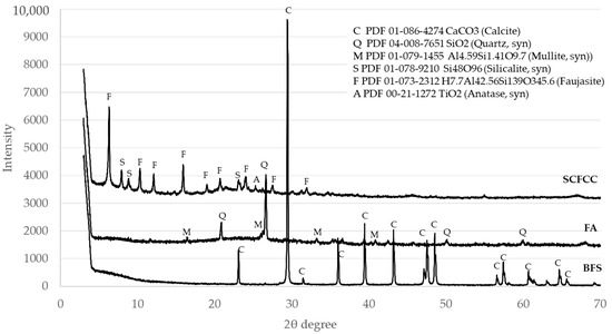
Figure 1.
X-ray diffractograms of raw materials.
Diffractograms of BFS- and FA-based AAMs are shown in Figure 2 and Figure 3. The XRD patterns of BFS100-SCFCC0 show the presence of calcite (PDF 01-086-4274) and bütschliite (PDF 04-010-1207). The amorphous content of the BFS100-SCFCC0 AAM was 55.6%. The XRD patterns of BFS75-SCFCC25 only showed calcite as a mineral phase. The amorphous content was 61.3%. The X-ray diffractograms of FA100-SCFCC0 showed the presence of quartz (PDF 04-008-7651), mullite (PDF 01-079-1455), kalicinite (PDF 00-012-0292) and gonnardite (a potassium aluminium silicon oxide hydrate) (PDF 04-017-3349). The amorphous content calculated by DIFFRAC.EVA software was 52.3%. The XRD patterns of FA75-SCFCC25 also showed quartz and mullite. No other crystalline phases were visualized, and the amorphous content was 56.6%.
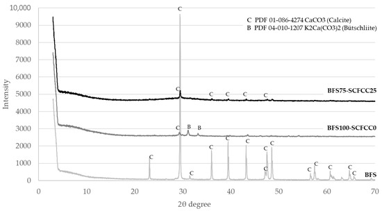
Figure 2.
X-ray diffractograms of BFS, BFS100-SCFCC0 and BFS75-SCFCC25.
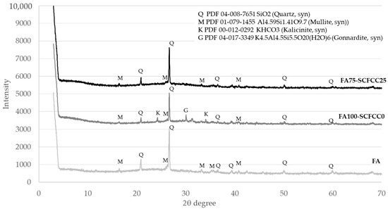
Figure 3.
X-ray diffractograms of FA, FA100-SCFCC0 and FA75-SCFCC25.
2.2. Total Porosity and Density
Total porosity (as pore volume) of the four AAMs with the time are detailed in Table 1. Pore size distribution is visualized in Figure 4.

Table 1.
Porosity as pore volume of AAMs.
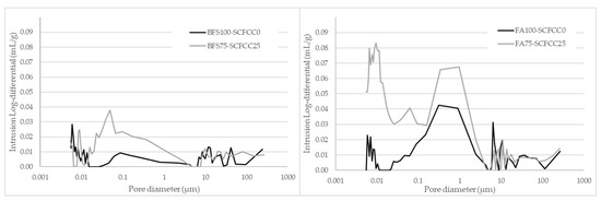
Figure 4.
Pore size distribution of AAMs.
As can be seen in Table 1, the AAM based on BFS (BFS100-SCFCC0) was less porous than the FA-based one (FA100-SCFCC0). Regarding to the evolution with time, from day 1 to day 28, a decrement of porosity happened in all the AAMs. BFS-based AAMs presented densities of 2311 ± 23 kg/m3 (BFS100-SCFCC0) and 2025 ± 22 kg/m3 (BFS75-SCFCC25). FA-based AAMs presented densities of 1973 ± 21 kg/m3 (FA100-SCFCC0) and 1776 ± 13 kg/m3 (FA75-SCFCC25) at 28 days of curing. Figure 4 shows the pore size distribution (PSD) at 28 days of curing. Different PSD of AAMs based on BFS and FA can be observed. BFS100-SCFCC0 shows certain bimodality with two peaks of pore volume around 10 µm and 0.01 µm, and with almost no pores between 0.1 and 5 µm. FA100-SCFCC0 shows a trimodal patterns, with the highest concentration of pores around 0.01 µm, between 0.07 and 5 µm and higher than 10 µm.
The addition of SCFCC to the AAMs mixture results in an increase in total porosity (see Table 1) and a decrease in density. Table 1 also showed that SCFCC induces more significant changes in BFS-AAM than in FA-AAM. The reduction of density and increment of porosity were around 12% and 58%, respectively, in BFS-AAMs, while they were 10% and 36%, respectively, in FA-AAMs. Besides, and as shown in Figure 4, the incorporation of SCFCC into BFS- and FA-based AAMs leads to an increase in pore volume, particularly in pores with diameters smaller than 4–5 µm, accompanied by a reduction in the volume of larger pores. The distribution of pore volume across different pore size ranges (according to IUPAC), macropores (0.05–300 µm) and mesopores (0.002–0.05 µm), is detailed in Table 2. A further subdivision into small macropores (0.05–5 µm) and large macropores (5–300 µm) proportions has also been carried out. The data corroborate the reduction of macroporous volume proportion due to the incorporation of SCFCC into the matrix.
Table 2.
Percentage of mesoporous and macroporous proportion in AAMs.
2.3. Mechanical Properties
Figure 5 shows the values of compressive strength (CS) (MPa) of samples during the time of curing (1–28 days). Variation coefficients of compressive strength were lower than 7%.
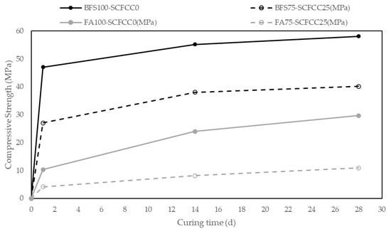
Figure 5.
Evolution of compressive strength along the curing time.
The first point of information that can be obtained from these results is that the 100% BFS-AAM is emphatically the leading mixture in CS, with a value of 58.06 MPa at 28 days. The 100% FA-AAM presented a value of 29.7 MPa at 28 days. The addition of SCFCC to the mixture leads to a decrease in compressive strength.
Regarding the evolution with the time, a great increment of compressive strength is observed in one day in BFS-AAM, reaching almost the maximum value of compressive strength at 14 days, with a slight increase of CS from 14 days to 28 days. However, for FA-AAM, the maximum values were reached later, at 28 days. The incorporation of SCFCC into the matrix led to a reduction in the reaction rate at the early stages (1 day). From day 1 to day 28, the curves with and without SCFCC follow the same trend.
2.4. Acid Attack Test
The evaluation of the acid attack test (data from acid and from water (as reference) tests) has been carried out using the following parameters: mass variation (%) after and before the test; ratio between CS values after and before the attack (reference values at 28 days—Figure 5) attack; total porosity and pore size distribution after and before the test.
Figure 6 shows the value of mass variation and ratio of CS of all AAMs studied. Variation coefficients of mass variation range 2–3% and of compressive strength range 1–8%.
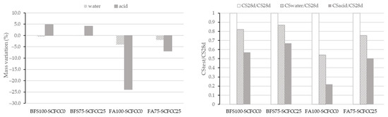
Figure 6.
Mass variation (left) and compressive strength ratio (right) after acid attack.
Regarding the mass variation results, the effect of immersion in acid or water is more pronounced in FA-based AAMs compared to BFS-based ones. It can also be observed that the effect of water immersion is less important than that of acid immersion. Water exposure resulted in only negligible mass loss in the BFS-based AAM and a comparatively lower mass loss in the FA-based AAM than that observed under acidic conditions.
To further investigate the behaviour of the materials, the acid neutralization capacity of the raw material (BFS, FA, and SCFCC) and BFS100-SCFCC0 and FA100-SCFCC0 were evaluated using the GANC test [38]. Figure 7 presents the relationship between the pH of the samples and the amount of acetic acid added (expressed as equivalents per kilogram of material). This analysis provides insights into the buffering capacity and chemical stability of the AAMs under acidic conditions. As can be seen, BFS exhibited a higher acid neutralization capacity than FA, as evidenced by the lower pH variation per eq/kg of acid added and the gentler slope of the neutralization curve. SCFCC presented pH value in the range of 3–6, with the value of pH practically constant between 1 and 6 eq/kg. BFS100-SCFCC0 and FA100-SCFCC0 AAMs exhibited the same behavior as their respective precursors.
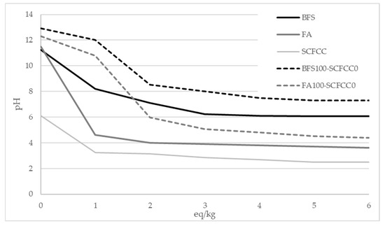
Figure 7.
Acid neutralization capacity. pH vs eq/kg.
The incorporation of SCFCC into the FA-based AAM resulted in reduced mass loss after immersion in acid and water. In the BFS-based AAM, SCFCC addition led to lower mass loss after water immersion and reduced mass gain after the acid exposure.
The results of CS variation expressed as the ratio between the CS after the test and the initial CS at 28 days, are presented in Figure 6 (right). As can be seen, there was a decrement of CS after the immersion in water and acid of the four AAMs. The FA-AAMs were less resistant than the BFS-AAMs, which is due to the high mass loss visualized in Figure 6 (left). The incorporation of SCFCC led to lower reductions of the CS ratio.
Total porosity as pore volume (Table 3) was also analysed after the immersion in water and in acid solution.
Table 3.
Evolution of total porosity (as pore volume) after water and acid immersion.
The water immersion produced an increment of porosity, more pronounced in FA-AAMs than in BFS-AAMs and less important in AAMs with SCFCC. However, the acid immersion produced different effects in BFS- and FA-AAMs: a reduction of porosity in BFS-based AAMs and an increment of porosity in FA-ones. Figure 8 shows the pore size distribution of BFS-based AAMs and FA-based AAMs before and after the acid immersion.
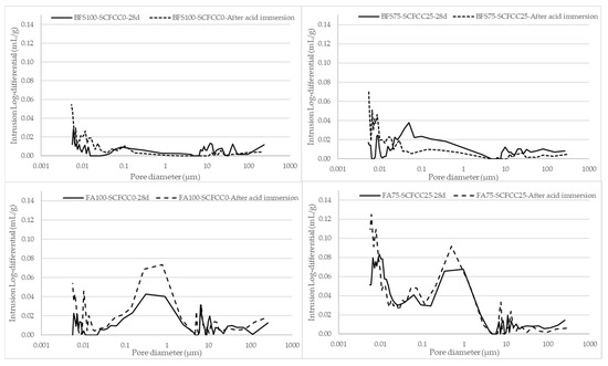
Figure 8.
Pore size distribution of AAMs before and after acid immersion.
The bimodal pattern of BFS-based AAMs observed in the PSD at 28 days disappears, as the pore volume in pores larger than 0.1 µm in BFS100-SCFCC0 and larger than 0.04 µm in BFS75-SCFCC25 becomes practically negligible. Conversely, a slight increase in pore volume is observed in the smallest pore size range. The pore size distribution graphs for FA100-SCFCC0 and FA75-SCFCC25 maintain the trimodal pattern; however, a significant increase in pore volume is observed in pores smaller than 2 µm for FA100-SCFCC0 and smaller than 1 µm for FA75-SCFCC25. The volume of pores larger than these thresholds remains unchanged.
Figure 9 shows the photographs of samples after acid immersion, A: BFS100-SCFCC0; B: BFS75-SCFCC25; C: FA100-SCFCC0; and D: FA75-SCFCC25.
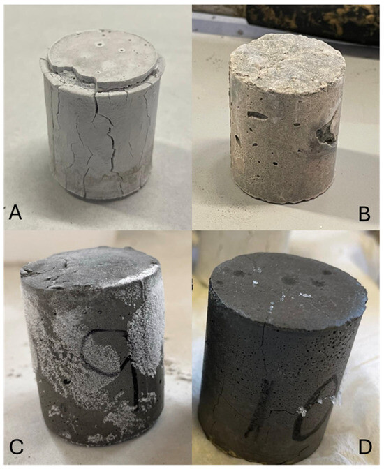
Figure 9.
Samples after acid attack. (A) BFS100-SCFCC0; (B) BFS75-SCFCC25; (C) FA100-SCFCC0; and (D) FA75-SCFCC25.
2.5. Accelerated Weathering Test in Simulated Warm-Humid Conditions
As was performed in the acid attack analysis, mass, compressive strength and total porosity (as pore volume) were analysed after the test and compared with the values before the test. Table 4 shows the values of total pore volume before and after the accelerated weathering test. Figure 10 shows the value of mass variation and ratio of CS of all AAMs subjected to the test. Variation coefficients of mass variation range 2–3% and of compressive strength range 2–7%.
Table 4.
Total porosity (as pore volume) after the accelerated weathering test.
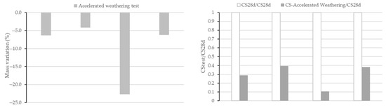
Figure 10.
Mass variation (left) and compressive strength ratio (right) after the accelerated weathering test.
An increment of total porosity (57.4% in BFS100-SCFCC0, 15.3% in BFS75-SCFCC25, 75.6% in FA100-SCFCC0 and 21.1% in FA75-SCFCC25) was observed after the accelerated weathering test, with a lower increment in BFS-AAMs and when SCFCC was incorporated into the matrix. A mass loss and a reduction of the CS were also observed in accordance with the values of porosities. The incorporation of the SCFCC into the mixture resulted in AAMs with the lowest increment of porosities and mass loss, and therefore the highest CS ratio.
BFS100SCFCC0 (left) and FA100SCFCC0 (right) AAMs photographs after the accelerated weathering test are shown in Figure 11.
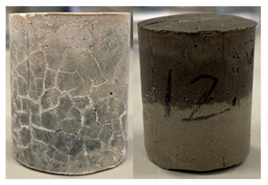
Figure 11.
BFS100SCFCC0 (left) and FA100SCFCC0 (right) samples after the accelerated weathering test.
3. Discussion
Alkali-activated BFS and FA were manufactured without any difficulty and showed thixotropy and great workability. When the SCFCC was incorporated into the mixture, the behaviour of the blends changed, and water was required to improve the workability. Payá et al. [6] studied fluid catalytic cracking catalyst residue to enhance the early strength of cement mixtures. They reported that the presence of connected polyhedral cavities in the zeolite structure of the catalyst permits the absorption of water, resulting in a water demand when this material is added to cement mixtures.
The first results presented in the work were the XRD patterns. Calcite is the main phase observed in the BFS. Calcite and bütschliite were observed in the BFS100-SCFCC0 sample. The intensities of peaks of calcite in the XRD pattern of BFS decrease remarkably in comparison with the peak in BFS100-SCFCC0. Some authors [39] reported the disappearance of calcite after the alkaline attack of slags. Besides, calcite may dissolve in alkaline conditions [40] demonstrating that this phase, either partial or whole, can dissolve during the activation. The products of the dissolution may react and form the C–(N)–A–S–H gel (characteristic gel of alkali (sodium) silicate-activated slag systems [41]). In addition, CaCO3 could participate in the formation of bütschliite which also appeared in the BFS100-SCFCC pattern. The formation of bütschliite (K2Ca(CO3)2) from the CaCO3 evidences the presence of available K+ ions of the alkali activation, which is possibly attributed to an excess of this alkali [42]. The amorphous content of the BFS100-SCFCC0 AAM was 55.6%, which is indicative of the formation of the amorphous gel formed in alkali silicate-activated slag systems. The XRD patterns of BFS75-SCFCC25 only showed calcite as crystalline phase, but in a lower proportion than in the BFS. The zeolitic phases of SCFCC, silicalite and faujasite, did not appear in the diffractogram, likely due to the zeolitic phases have been activated during the geopolymerization reaction [34]. DIFFRAC.EVA provides an amorphous content of 61.3%, higher than in BFS100-SCFC0, which can be attributed to the formation of products by the alkali attack of zeolites. In addition, SCFCC presented a higher amorphous content (40.8%) than BFS (13.2%), which also may react with the activating solution.
The XRD pattern of FA100S-CFCC0 showed quartz and mullite, the same crystalline phases as the FA. Kalicinite and gonnardite were also visualized. Kalicinite is a KHCO3 possibly formed due to the phenomenon of carbonation of the sample. Gonnardite ((Na,Ca)2(Si,Al)5O10·2H2O) is a zeolite resulting from the activation of ashes with sodium-based activator [43]. In this work, K-based activators have been used, so the gonnardite (PDF 04-017-3349), a potassium aluminium silicon oxide hydrate, was observed. The amorphous content of the raw fly ash (FA) was 50.7%. After alkali activation, the amorphous content in the FA100-SCFCC0 AAM was 52.3%, which is indicative of the formation of K-A-S-H gel, characteristic in FA activated with potassium silicates [44]. With the incorporation of SCFCC into the FA matrix, the amorphous content further increased to 56.6%. As well as being observed in BFS-based AAMs, the increase in amorphous content in FA75-SCFCC25 may be attributed to the partial dissolution of zeolitic and vitreous phases in the SCFCC. This dissolution can contribute additional amorphous gel to the system.
Total porosity, density and compressive strength of the AAMs were also evaluated. BFS-based AAMs were less porous and denser than FA-based ones. These results may be explained by a combination of physical and chemical factors. Firstly, the physical characteristics of the raw materials—BFS and FA—play a significant role. BFS has finer particles and is denser compared to FA (specific gravity of BFS and FA are 2.93 and 1.93 g/mL respectively), which enhances its reactivity with the alkaline solution and contributes to a more efficient geopolymerization process. Secondly, the chemical composition of the raw materials significantly affects the nature of the reaction products. BFS is rich in calcium (43.5 wt% of CaO), whereas FA contains relatively low calcium content (3.94 wt% of CaO). When FA is activated with potassium silicate, the primary reaction product is K-A-S-H (potassium alumino silicate hydrate) gel; in contrast, the activation of BFS with potassium silicate results in the formation of both K-A-S-H and C-A-S-H (calcium alumino silicate hydrate) gels [44]. Puligilla and Mondal [45] proposed that the simultaneous formation of the geopolymeric gel (K-A-S-H gel in the current work) and the C-A-S-H gel in BFS-based AAMs may help to fill the gaps between the different hydrated phases and the unreacted particles, resulting in a denser and more homogeneous matrix. Therefore, these differences in gel composition directly affect the microstructure development and, consequently, the porosity, density and mechanical properties of the AAMs matrix.
Regarding the evolution with time, from day 1 to day 28, a decrement of porosity happened in all the AAMs studied. The evolution of porosity over time is attributed to the progressive formation of geopolymerizaton products, which occupy and fill the pore space contributing to the closing of the pores. This process leads to a continuous decrease in porosity and the corresponding increase in density and compressive strength.
The addition of SCFCC to the AAMs mixture results in a decrease in density and an increase in total porosity (see Table 1). At first, this overall increase in porosity may be attributed to the additional water required in the SCFCC-containing AAM to facilitate the mixing of the paste and the SCFCC particles. During the curing process, the evaporation of the water can lead to pores formation. SCFCC also induces more significant changes in BFS-AAM than in FA-AAM due mainly to the higher amount of water requirements (ratio 0.1 in BFS-AAMs and 0.07 in FA-AAM). To further investigate the total porosity of samples, the pore size distribution was evaluated. As shown in Figure 4, the incorporation of SCFCC into BFS- and FA-based AAMs leads to an increase in the total pore volume. However, the increase in pore volume occurs particularly in pores with diameters smaller than 4–5 µm, accompanied by a reduction in the volume of larger pores. Table 2 presents the distribution of pore volume percentages within the mesopore range (0.002–0.05 µm) and the macropore range (0.05–300 µm), further subdivided into small macropores (0.05–5 µm) and large macropores (5–300 µm). The data show an increase in the percentage of pore volume associated with mesopores and a decrease in macropore volume, particularly within the large macropore range, with the incorporation of SCFCC. To explain this result, several factors should be considered. First, the improved packing efficiency resulting from the broader particle size distribution of SCFCC (ranging from 40 to 180 µm) likely contributes to the reduction in pore volume within the 5–300 µm range. Larger particles can fill voids more effectively when combined with smaller ones, leading to a denser matrix structure. Second, the increase in pore volume in sizes less than 5 µm may be attributed to a higher water content, as commented before, which, upon evaporation, can lead to pores formation. Additionally, the formation of a new phase following the activation of the zeolitic and amorphous content of SCFCC (primarily K-A-S-H gel) should be considered. The formation of the C-A-S-H gel is not expected due to the very low calcium content in SCFCC (0.04 wt%). This newly formed phase may initially contribute to pore refinement by partially filling the voids, thereby reducing macroporosity. However, this new gel could have a different composition (K + Ca ratio in the gel) [46] than the gel formed after the BFS activation (C-A-S-H and K-A-S-H gel) and could show lower differences to the gel derived from the FA activation (K-A-S-H gel). These differences in gels originating from distinct raw materials could lead to the development of porous interfacial zones between the gels and unreacted particles, creating pores in the mesopore zone. This phenomenon could account for the increased mesoporosity detected in the BFS75–SCFCC25.
In relation to the compressive strength results, the 100% BFS-AAM is emphatically the leading mixture in CS, with a value of 58.06 MPa at 28 days. The 100% FA-AAM presented a value of 29.7 MPa at 28 days. As previously commented, FA100-SCFCC0 was less dense and more porous than BFS100-SCFCC0. The addition of SCFCC to the mixture leads to a decrease in compressive strength, which can be attributed to the lower density and higher total porosity caused by its incorporation.
Another interesting aspect to evaluate is the rate of the reaction. BFS-AAM exhibited a great increment of compressive strength in one day, reaching almost the maximum value of compressive strength at 14 days, with a slight increase of CS from 14 days to 28 days. However, the FA-AAMs presented the maximum value later, at 28 days. These behaviours are corroborated with other studies [47,48], which show that BFS-based AAMs exhibit rapid strength development. This is due to their high calcium content, which promotes the formation of both C-A-S-H and N-A-S-H (K-A-S-H gel in the current work). This hybrid gel accelerates the setting and early strength development. The addition of SCFCC to the matrix led to a significant reduction in the early-age reaction rate (1 day), as reflected by the decrease in CS from 48 MPa to 27 MPa in BFS-based AAMs, and from 10 MPa to 4 MPa in FA-based systems, while the curves exhibited the same trend from 1 day to 28 days. The reduction in early-age CS may be attributed to the dilution effect introduced by the SCFCC in the binder matrix. Additionally, as SCFCC interacts with the alkaline solution, the availability of OH− and silicate species for the dissolution and subsequent polycondensation of the primary precursors (BFS and FA) could be reduced. This competition may lead to a slower formation of the binding gels associated with BFS and FA, particularly at early curing ages.
The results of the acid attack test showed that FA100-SCFCC0 were less resistant to the acid attack than BFS100-SCFCC0. This difference is likely attributed to the more porous macrostructure of the FA-AAM, as observed in Figure 4 and Table 2 (percentage of macroporous volume was 54.4% and 70.6% for BFS100-SCFCC0 and FA100-SCFCC0, respectively), which facilitates greater ingress of water or acidic solutions. The higher porosity increases the exposure surface of the internal matrix to degradation mechanisms, leading to more significant mass changes over time.
FA100-SCFCC0 showed a loss of mass during the test, stronger after the immersion in acid than in water. On the contrary, BFS100-SCFCC0 showed a gain of mass after the immersion in acid and a slight loss of mass after the immersion in water. Some studies try to explain the loss of mass [49]: when an AAM is brought into contact with water or an acid solution (like sulfuric acid), the alkali cation, K+ in this work, is replaced in polymers by other molecules, such as hydrogen or hydronium cations. This would lead to a mass reduction due to the lack of the presence of alkali cations that are involved in the stronger geopolymeric frameworks [49]. Moreover, if an AAM interacts with a strong acid, it attacks the aluminosilicate framework and leads to dealumination so that many Si–O–Al bonds are broken, and there is an increase in the Si–OH and Al–OH groups. There will also be more silicic acid ions and dimers in the acid solution. These facts also lead to mass loss in AAM materials [49].
Although this statement depends on the nature of the fly ash used, the blast furnace slag does not lose mass. The literature [50] on BFS-based AAMs dictates the following constraint: this type of AAM should also lose weight when exposed to acid media. This issue is based on the idea of the dissolution of K and Al ions from AAMs in the sulfuric acid and on the reasons explained below. However, during exposure to the sulfuric acid attack BFS-AAM showed a gain of mass. Bernal et al. [51] indicate that the Ca-rich alkali-activated material (such as BFS) may suffer from decalcification and dealumination and form products such as gypsum. On the contrary, in low-Ca alkali activated materials (such as FA), in which the main reaction products are the alkali alumino silicate hydrate gel (N-A-S-H gel) with zeolite-like products [52], the degradation of the N-A-S-H gel under sulfuric acid attack involves ion exchange, dealumination, and then poly condensation, eventually turning this gel into a highly-polymerized aluminosilicate or silicate frameworks, with no gypsum precipitation due to the low Ca concentration [53].
The acid neutralization capacity was assessed to provide a comprehensive understanding of material behavior when exposed to acidic or aqueous environments. As can be seen in Figure 7, BFS exhibited a higher acid neutralization capacity than FA, as evidenced by the lower pH variation per eq/kg of acid added and the gentler slope of the neutralization curve. This indicates that BFS is more resistant to acid attack compared to FA. A similar trend was observed in the AAM samples, with 0 eq/kg (water) the pH values of BFS100-SCFCC0 and FA100-SCFCC0 were 12.92 and 12.31, respectively. However, with 6 eq/kg (acid), the pH value drops 6.17 points in BFS100-SCFCC0 and 7.73 points in FA100-SCFCC0). Therefore, BFS100-SCFCC0 demonstrated greater acid neutralization capacity than FA100-SCFCC0. A higher acid neutralization capacity implies increased alkalinity, which enhances the material buffering ability upon exposure to acidic environments. Consequently, the pH reduction within the matrix is attenuated, minimizing gel dissolution and structural degradation. This results in reduced mass loss and minimal changes in the pore structure, indicating that BFS-based AAMs offer enhanced resistance to acid degradation. This improved resistance may be associated with a delayed dealumination process in the gel phase, as previously reported [54].
The incorporation of SCFCC into the FA and BFS-based AAM resulted in a reduction in the degree of deterioration. This improvement can be attributed to the decrease in pore volume in the range of the larger pores (between 5–300 µm), due to the presence of SCFCC. This effect was less pronounced in the FA-based AAM, likely due to the reduced proportion of larger pores (see Table 2), which may have limited the penetration of water and acid into the matrix, thereby enhancing its resistance to chemical attack.
Regarding the results for CS of FA-AAMs after the acid attack test, these are correlated with the observed mass loss, which is indicative of structural degradation. BFS-based AAMs also exhibited a reduction in CS following immersion in water and acid. This behaviour is not correlated with the mass gain observed (likely associated with the formation of a new calcium sulphate phase [51]). It is possible that the formation of this new phase may have contributed to a weakening of the microstructure, ultimately reducing the mechanical strength. The incorporation of SCFCC led to lower reductions of CS ratio, which are associated with lower mass loss and reduced pore volume in the range of larger pores (5–300 µm).
To further investigate the effect of acid immersion in both types of AAMs, pore size distributions were analysed (see Figure 8). In the case of BFS-AAMs, the acid exposure led to a decrement of pore volume in pores larges than 0.1 µm (and 0.04 µm when SCFCC was incorporated into the matrix). This is possibly because of the pore filling effect of the new calcium sulphate phase generated during the acid attack. On the contrary, there is an increment of finer pores due to the neutralization and dealumination process occurring in the gel pores. FA-AAMs showed an increment of pore volume in pore sizes smaller than 2 µm (and 1 µm when SCFCC was incorporated into the matrix). Due to the low calcium content in FA, the formation of calcium sulphate phases is negligible, particularly when compared to BFS-based AAMs. As a result, there is no secondary phase available to fill the pores. The greater increase in total porosity after the acid attack observed in FA-based AAMs is mainly attributed to the chemical degradation of the microstructure, driven by the low acid neutralization capacity of the matrix. This leads to a significant drop in pH under acidic conditions, which in turn promotes dealumination and further neutralization reactions, resulting in deterioration of the gel phase and an increase in porosity. Furthermore, it must be considered that FA-based AAMs presented the largest proportion of macroporosity, which facilitates the penetration of acid into the matrix.
Water immersion also resulted in an increment of total porosity of samples, which was more pronounced in FA-based AAMs than in BFS-based ones and less important in AAMs containing SCFCC. This increase can be attributed to neutralization reactions between the pore solution and the geopolymeric matrix, which lead to microstructural degradation. As commented before, the BFS-based AAM (BFS100-SCFCC0) exhibited higher acid neutralization capacity than the FA-based one (FA100-SCFCC0) and a low proportion of macropores (54.4%), so it also shows better resistance to water immersion.
Exposure to water induced a lower important degradation than acid exposure. This behaviour aligns with the intrinsic acid neutralization capacity of the respective matrices, which governs their resistance to aqueous environments, as previously discussed. It was also observed that samples exposed to water underwent less degradation than those immersed in acidic solutions. Given the high intrinsic alkalinity of alkali-activated materials, immersion in acidic media induces a more intense neutralization reaction compared to water exposure, as the reduction in pH is significantly greater under acidic conditions than in neutral aqueous environments.
Figure 9 shows the AAM samples after the acid immersion. BFS100-SCFCC0 presented superficial whitening, which confirm the formation of a calcium sulphate phase. An expansion and spalling phenomenon can also be observed. The crystallization of the neutralization reaction products may lead to internal tensile stress and contributes to this expansion and spalling [55]. FA100-SCFCC0 also presented a slight swelling of the material, but in a different form from BFS100-SCFCC0. In this case, where no calcium sulphate phase is formed, the expansion may be attributed to the absorption of water/acid into the more porous and degraded regions of the FA-AAM matrix. Additionally, the presence of some crystals, possibly potassium sulphate, was observed. Samples BFS75-SCFCC25 and FA75-SCFCC25 presented lower deterioration than the respective samples without SCFCC. BFS75-SCFCC25 exhibited a slight white layer and FA75-SCFCC25 showed negligible presence of crystals.
Regarding the accelerated weathering test, the four AAMs presented mass loss, a decrement of total porosity and a reduction in CS. In general terms, the damage suffered by these samples was associated with a significant increase in porosity after the exposure to water-steam generated during the test. BFS100-SCFCC0 showed better behaviour than FA100-SCFCC0, likely due to the lower macroporosity (54.4%), as can be seen in Table 2. As a result of the test, a notable increment in porosity was observed, 57.4% and 75.6% in the BFS- and FA-based AAMs, respectively (Table 4). Some studies [56] on durability under steam exposure show that AAMs may suffered leaching of alkali ions such as sodium or potassium, which can lead to efflorescence and an increment of porosity over the time. Other research [57] indicates that prolonged exposure to humid environments can lead to microstructural alterations, such as increased pore connectivity, which may affect mechanical properties.
Figure 11 shows photographs of BFS100SCFCC0 (left) and FA100SCFCC0 (right) after the simulated warm-humid conditions. As can be seen, the BFS100SCFCC0 shows external cracks while the FA100SCFCC0 shows some swelling. The effects observed in the current test are comparable to those of steam curing, suggesting that similar outcomes could be achieved. Studies [58,59] on the effect of steam curing in concrete showed that the rapid temperature changes and moisture gradients during steam curing contribute to internal stresses. This leads to microcrack development including pronounced volumetric deformation, shrinkage, surface microcracking, pore structure coarsening and reduced long-term durability.
The incorporation of the SCFCC into the mixture resulted in materials with the highest resistance to this test. It must be considered that, as well as happened in the acid attack experiment, the SCFCC in both AAMs resulted in a decrement of the proportion of pores larger than 5 µm (effect more important in the FA-AAM), so the penetration of water steam into the matrix could be limited.
4. Conclusions
As a primary conclusion, it can be established that in general terms the alkali-activated blast furnace slag has better mechanical and durability properties than those based on fly ash. The compressive strength values of BFS-AAMs at 28 days (58.06 MPa for BFS100-SCFCC0, and 40.1 MPa for BFS75-SCFCC25) support its viability as a substitute for OPC. On the contrary, the lower CS values of FA-AAMs (29.7 MPa for FA100-SCFCC0, and 10.9 MPa for FA75-SCFCC25) compared to OPC (32.5 MPa) suggests its suitability for alternative applications, such as use as a road binder [60]. In this case, leaching behavior should be analyzed, which could be addressed in future studies.
The incorporation of SCFCC into the matrix leads to an increase in total porosity (total pore volume), but this increase is associated with the pores smaller than 5 µm (an increase in the proportion of pore volume in sizes smaller than 5 µm is observed compared to the samples without SCFCC). On the contrary, the incorporation of SCFCC into the matrix reduces the proportion of pores larger than 5 µm when compared to the samples without SCFCC. As the incorporation of SCFCC results in an overall increase in total porosity, this adversely impacts in the mechanical performance of the material. However, the concurrent reduction in the volume of macropores contributes to improving the durability, as it restricts the ingress of aggressive external agents, thereby improving resistance to environmental degradation.
5. Materials and Methods
5.1. Materials
A coal combustion fly ash (FA) was supplied by a coal-fired power plant located in southern Spain. The blast furnace slag (BFS) was provided by a steel and mining company in northern Spain. The spent fluid catalytic cracking catalyst (SCFCC) was obtained from a Spanish oil refinery. The chemical composition has been determined by Atomic Absorption Spectrophotometry after the digestion of the samples at 750 °C (ASTM D-3682-78) [61]. Major elements are shown in Table 5.
Table 5.
Major chemical composition of solid raw materials.
The SCFCC also contains P2O5 (3.21 wt%), La2O3 (0.79 wt%), Ni2O3 (0.18 wt%), and TiO2 (1.90 wt%), completing the total to 100 wt%. As can be seen, FA shows an elevated amounts of SiO2 and Al2O3, while BFS is mainly a source of CaO and SiO2. SCFCC also show SiO2 and Al2O3 as main oxides.
The trace elements and their concentrations have been measured through Inductively Coupled Plasma Atomic Emission Spectroscopy. They are shown in Table 6. As can be observed, FA presents high concentration of Ba, Cr, As, Zn and V. Ba is also observed in BFS.
Table 6.
Trace elements in solid raw materials.
The specific gravity of the solid phase was also measured according to the ASTM C127-93 standard [62] being the values in g/mL: FA = 1.930 ± 0.001, BFS = 2.93 ± 0.01, and SCFCC = 3.15 ± 0.00. The values for specific gravity are in accordance with the LOI percentage (carbonaceous fraction) since this phase is considered a very porous phase [63].
Particle size distribution was analysed using a high-definition digital particle size analyser (Micromeritics, Saturn DigiSizer II model). Figure 12 shows the results of cumulative representation. D50 of BFS, FA, and SCFCC was 11.5, 13.3, and 90 µm, respectively. BFS is the finer material, followed by the FA, and the SCFCC is the thickest.
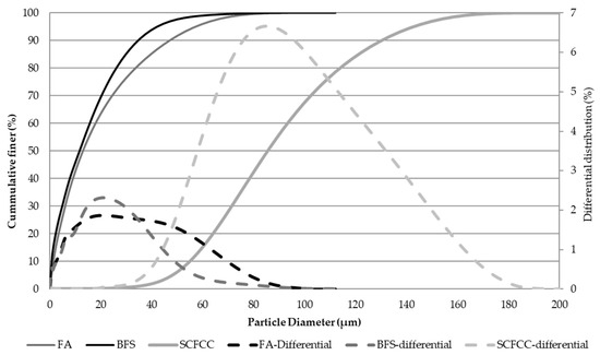
Figure 12.
Particle size distribution of solid raw materials.
The alkali-activating solution (AAS) used was a mixture of potassium silicate (supplied by Industrias Químicas del Ebro SA) and potassium hydroxide (supplied by MERCK) with a purity of 85 w%. SiO2, K2O, and water contents of the potassium silicate solution were 23 wt%, 14.9 wt%, and 62.1 wt%, respectively, with a weight ratio K2O/SiO2 of 0.647. KOH is added to the potassium silicate solution to obtain a final molar ratio K2O/SiO2 of 0.98.
The composition of the samples is detailed in Table 7. Two types of AAMs were manufactured: one based on BFS and the other on FA (both without and with SCFCC). The AAMs without SCFCC were prepared as follows. Firstly, the solid phase (BFS or FA) was placed in a planetary dough mixer. Then, the AAS was added and mixed until a workable material with thixotropic properties was obtained. The resulting pastes were poured into cylindrical plastic moulds (30 mm in diameter and 40 mm in height), with their bases covered with paraffin paper and vibrated on a vibrating table for 3 min. This vibration facilitated the filling of the moulds and helped eliminate entrapped air.
Table 7.
Formulations of alkali-activated materials.
The AAMs with SCFCC were manufactured in a similar way to those prepared without SCFCC, but incorporating of SCFCC into the solid phase (BFS or FA) and mixing for 4 min. Then, the AAS was added using the same AAS-to-main precursors ratio. Due to difficulties encountered during the mixing of the components, additional water was required to improve the integration of the materials into the overall mixture. The resulting pastes were then placed into cylindrical plastic molds and vibrated on a vibrating machine for 3 min.
All AAMs were cured in an oven at 60 °C for 16 h to harden. They were then demolded and left to set under laboratory conditions (25 °C).
5.2. Methodology
X-ray diffraction analysis (XRD) of raw materials and AAMs was carried out using a D8 Advance A25 (BRUKER) (40kV and 30mA) instrument and DIFFRAC-EVA software 5.2.0.3 version (BRUKER) was used for phase identification. JCPS data were PDF-4.2022.
Bulk density was calculated according to UNE EN 1936 [64] after 28 days of curing. The average dimensions of the cylindrical samples were 38–43 mm high and 32–34 mm in diameter. Four specimens of each sample were tested. Total porosity and pore size distribution were analysed by means mercury intrusion porosity using the PoreMaster 60GT also after 1, 14, and 28 days of curing.
The compressive strength test was carried out according to standard ASTM C39/C39M [65] after 1, 14, and 28 days of curing using a Tinius Olsen-TO317EDG. Three specimens of each sample were tested.
After 28 days of hardening, AAM were subjected to two tests. In the first case, AAMs were submitted to an acid attack test. The acid attack was based on the immersion of the samples in sulfuric acid (1M) (pH 0) in a liquid/solid ratio of 3 (specimens must be fully immersed in the solution throughout the test) for 14 days, following the protocol of Cerulli et al. [66]. There is no renewal of the acid solution during the test. Therefore, to prevent evaporation of the solution, the containers used for the test are covered with paraffin paper. The test was carried out at 25 °C. For comparison reasons, specimens of the samples were also immersed in tap water for 14 days. The same procedure as with acid was followed. Four specimens of each sample were tested. After the test, samples were completely dried under ambient conditions. Mass loss, porosity by means mercury intrusion porosimetry and compressive strength were then evaluated.
In the second case, an accelerated weathering test simulating real environmental conditions typical of warm and humid regions was also carried out. Four samples of each AAM were put in a tray with wet sand. The tray was introduced in an oven a 60 °C for 20 days. Sand was moistened daily to maintain the water content in the sand. The objective of this test is simulating the behaviour of the material forming part of a structure buried in the soil and exposed to extreme environmental temperature. On the one hand, the bottom of the sample absorbs water by means capillarity (as in real situation), and on the other hand, the rest of the sample is exposed to a temperature of 60 °C and to the water-steam generated as the water evaporates in the oven. Four specimens of each sample were tested.
Author Contributions
Conceptualization, Y.L.-G.; methodology, Y.L.-G. and C.L.F.; validation, M.R.-G.; formal analysis, D.C.-G., Y.L.-G. and R.M.N.; investigation, D.C.-G. and Y.L.-G.; resources, M.R.-G.; data curation, C.L.F.; writing—original draft preparation, D.C.-G. and Y.L.-G.; writing—review and editing, M.R.-G., Y.L.-G., C.L.F., J.A.L. and R.M.N.; visualization, M.R.-G.; supervision, C.L.F.; project administration, Y.L.-G. All authors have read and agreed to the published version of the manuscript.
Funding
This research received no external funding.
Data Availability Statement
The study did not report any data.
Acknowledgments
The authors acknowledge the Research, Technology, and Innovation Center of the University of Seville for access to the X-ray Laboratory facilities.
Conflicts of Interest
The authors declare no conflicts of interest.
Abbreviations
The following abbreviations are used in this manuscript:
| SCFCC | Spent catalyst from fluid catalytic cracking |
| FA | Fly ash |
| BFS | Blast furnace slag |
| AAS | Alkali-activating solution |
| AAM | Alkali-activated materials |
| PSD | Pore size distribution |
| CS | Compressive strength |
References
- Alonso-Fariñas, B.; Rodríguez-Galán, M.; Arenas, C.; Arroyo Torralvo, F.; Leiva, C. Sustainable management of spent fluid catalytic cracking catalyst from a circular economy approach. Waste Manag. 2020, 110, 10–19. [Google Scholar] [CrossRef]
- Dufresne, P. Hydroprocessing catalysts regeneration and recycling. Appl. Catal. A Gen. 2007, 322, 67–75. [Google Scholar] [CrossRef]
- Marafi, M.; Stanislaus, S. Spent catalyst waste management: A review. Part I-Developments in hydroprocessing catalyst waste reduction and use. Resour. Conserv. Recycl. 2008, 52, 859–873. [Google Scholar] [CrossRef]
- Sadeghbeigi, R. Chapter 9. Products and Economics. In Fluid Catalytic Cracking Handbook, 4th ed.; Sadeghbeigi, R., Ed.; Elsevier: Amsterdam, The Netherlands, 2020; pp. 163–182. [Google Scholar]
- Antiohos, S.K.; Chouliara, E.; Tsimas, S. Re-use of spent catalyst from oil-cracking refineries as supplementary cementing material. China Particuol. 2006, 4, 73–76. [Google Scholar] [CrossRef]
- Payá, J.; Monzó, J.; Borrachero, M. Fluid catalytic cracking catalyst residue (FC3R): An excellent mineral by-product for improving early-strength development of cement mixtures. Cem. Concr. Res. 1999, 29, 1773–1779. [Google Scholar] [CrossRef]
- Ruiz, G.; Aguilar, R.; Nakamatsu, J.; Kim, S. Synthesis of a geopolymer binders using spent fluid catalytic cracking (FCC) Catalyst. In Proceedings of the IOP Conference Series: Materials Science and Engineering, Riga, Latvia, 25–27 September 2019; Volume 660. [Google Scholar]
- Marafi, M.; Stanislaus, A. Options and processes for spent catalyst handling and utilization. J. Hazard. Mater. 2003, 101, 123–132. [Google Scholar] [CrossRef]
- Lu, G.; Lu, X.; Liu, P. Reactivation of spent FCC catalyst by mixed acid leaching for efficient catalytic cracking. J. Ind. Eng. Chem. 2020, 92, 236–242. [Google Scholar] [CrossRef]
- Rodríguez, E.D.; Bernal, S.A.; Provis, J.L.; Gehman, J.D.; Monzó, J.M.; Payá, J.; Borrachero, M.V. Geopolymers based on spent catalyst residue from a fluid catalytic cracking (FCC) process. Fuel 2013, 109, 493–502. [Google Scholar] [CrossRef]
- Kamichetty, J. Spend Fluids Cracking Catalyst (FCC)-A Potential Adsorbent for Organics in Hydraulic Fracturing Flowback. Master’s Thesis, Oklahoma State University, Stillwater, OK, USA, 2014. [Google Scholar]
- Nguyen, L.P.; Pham, Y.T.H.; Ngo, P.T.; Van Tran, T.; Vinh Tran, L.; Hoai Le, N.L.; Nguyen, L.H.; Dang, T.T.; Nguyen, D.A.; Wenzel, M.; et al. Production of high purity rare earth mixture from iron-rich spent fluid catalytic cracking (FCC) catalyst using acid leaching and two-step solvent extraction process. Korean J. Chem. Eng. 2018, 355, 1195–1202. [Google Scholar] [CrossRef]
- Niewiadomski, P.; Cisinski, M. The impact of waste fluid catalytic cracking catalyst addition on the selected properties of cement pastes. Mater. Proc. 2023, 13, 10. [Google Scholar]
- Bukowskaa, M.; Pacewskab, B.; Wilinska, I. Influence of spent catalyst used for catalytic cracking in a fluidized bed on sulphate corrosion of cement mortars: I. Na2SO4 medium. Cem. Concr. Res. 2004, 34, 759–767. [Google Scholar] [CrossRef]
- Hsiu-Liang, C.; Yun-Sheng, T.; Kung-Chung, H. Spent FCC catalyst as a pozzolanic material for high-performance mortars. Cem. Concr. Compos. 2004, 26, 657–664. [Google Scholar] [CrossRef]
- Nan, S.; Hung-Yuan, F.; Zong-Huei, C.; Fu-Shung, L. Reuse of waste catalysts from petrochemical industries for cement substitution. Cem. Concr. Res. 2000, 30, 1773–1783. [Google Scholar] [CrossRef]
- Su, N.; Chen, Z.H.; Fang, H.Y. Reuse of spent catalyst as fine aggregate in cement mortar. Cem. Concr. Compos. 2001, 23, 111–118. [Google Scholar] [CrossRef]
- Pacewka, B.; Willinska, I.; Bukowska, M.; Nocuri, W. Effect of waste aluminosilicate material on cement hydration and properties of cement mortars. Cem. Concr. Res. 2002, 32, 1823–1830. [Google Scholar] [CrossRef]
- Dweck, J.; Pinto, C.A.; Büchler, P.M. Study of a Brazilian spent catalyst as cement aggregate by thermal and mechanical analysis. J. Therm. Anal. Calorim. 2008, 92, 121–127. [Google Scholar] [CrossRef]
- Sofi, M.; Van Deventer, J.S.J.; Mendis, P.A.; Lukey, G.C. Engineering properties of inorganic polymer concretes (IPCs). Cem. Concr. Res. 2007, 37, 251–257. [Google Scholar] [CrossRef]
- Luna-Galiano, Y. Estudio de la Estabilización/Solidificación de Residuos Industrials Mediante la Tecnología de los Geopolímeros Basados en Cenizas Volantes Procedentes de Centrales Térmicas. Ph.D. Thesis, University of Seville, Seville, Spain, 2013. [Google Scholar]
- Papa, E. Geopolymers with Tailored Porosity. Ph.D. Thesis, University of Bologna, Bologna, Italy, 2016. [Google Scholar]
- Geopolymer Institute. Geopolymer Cement for Mitigation of Global Warming. 2006. Available online: https://www.geopolymer.org/applications/global-warming/# (accessed on 23 April 2025).
- Madirisha, M.M.; Dada, O.R.; Ikotun, B.D. A chemical fundamental of geopolymers in sustainable construction. Mater. Today Sustain. 2024, 27, 100842. [Google Scholar] [CrossRef]
- Furqan, F.; Xin, J.; Faisal Javed, M.; Akbar, B.A.; Izhar Shah, M.; Aslam, F.; Alyousef, R. Geopolymer concrete as sustainable material: A state of the art review. Constr. Build. Mater. 2021, 306, 124762. [Google Scholar] [CrossRef]
- Fernández-Pereira, C.; Luna-Galiano, Y.; Querol, X.; Antenucci, D.; Vale, J. Waste stabilization/solidification of an electric arc furnance dust using fly ash-based geopolymers. Fuel 2009, 88, 1185–1193. [Google Scholar] [CrossRef]
- Provis, J.L. Immobilisation of toxic wastes in geopolymers. In Geopolymers: Structures, Processing, Properties and Industrial Applications; Provis, J.L., van Deventer, J.S.J., Eds.; Elsevier: Amsterdam, The Netherlands, 2009; pp. 421–440. [Google Scholar]
- El-Eswed, B.I.; Yousef, R.I.; Alshaaer, M.; Hamadneh, I.; Al-Gharabli, S.I.; Khalili, F. Stabilization/solidification of heavy metals in kaolin/zeolite based geopolymers. Int. J. Miner. 2015, 137, 34–42. [Google Scholar] [CrossRef]
- Genua, F.; Lancellotti, I.; Leonelli, C. Geopolymer-based stabilization of heavy metals, the role of chemical agents in encapsulation and adsorption: Review. Polymer 2025, 17, 670. [Google Scholar] [CrossRef] [PubMed]
- Bai, C.M.; Colombo, P. Processing, properties and applications of highly porous geopolymers: A review. Ceram. Int. 2018, 44, 16103–16118. [Google Scholar] [CrossRef]
- Salazar, P.A.; Fernández, C.L.; Luna-Galiano, Y.; Sánchez, R.V.; Fernández-Pereira, C. Physical, Mechanical and Radiological Characteristics of a Fly Ash Geopolymer Incorporating Titanium Dioxide Waste as Passive Fire Insulating Material in Steel Structures. Materials 2022, 15, 8493. [Google Scholar] [CrossRef]
- Leiva, C.; Luna-Galiano, Y.; Arenas, C.; Alonso-Fariñas, B.; Fernández-Pereira, C. A porous geopolymer based on aluminum-waste with acoustic properties. Waste Manag. 2019, 95, 504–512. [Google Scholar] [CrossRef]
- Novais, R.M.; Carvalheiras, J.; Tobaldi, D.M.; Seabra, M.P.; Pullar, R.C.; Labrincha, J.A. Synthesis of porous biomass fly ash-based spheres for efficient removal of methylene blue from wastewaters. J. Clean. Prod. 2019, 207, 350–362. [Google Scholar] [CrossRef]
- Tashima, M.M.; Akasaki, J.L.; Castaldelli, V.L.; Soriano, L.; Monzó, J.M.; Payá, J.; Borrachero, M.V. New geopolymer binder based on fluid catalytic cracking catalyst residue (FCC). Mater. Lett. 2012, 80, 50–52. [Google Scholar] [CrossRef]
- Trochez, J.J.; Mejia de Gutierrez, R.; Rivera, J.; Bernal, S.A. Synthesis of geopolymer from spent FCC: Effect of SiO2/Al2O3 and Na2O/SiO2 molar ratios. Mater. Constr. 2015, 65, 317. [Google Scholar] [CrossRef]
- Das, B.B.; Narayana, N. Sustainable construction and building materials. In Proceedings of the Select Proceedings of ICSCBM 2018, Busan, Republic of Korea, 1–6 July 2018. [Google Scholar]
- Tashima, M.M.; Akasi, J.L.; Melges, J.L.P.; Soriano, L.; Monzó, J.M.; Payá, J.; Borrachero, M.V. Alkali activated materials based on fluid catalytic cracking catalyst residue (FCC): Influence of SiO2/Na2O and H2O/FCC ratio on mechanical strength and microstructure. Fuel 2013, 108, 833–839. [Google Scholar] [CrossRef]
- Isenburg, J.; Moore, M. Generalized acid neutralization capacity test. In Stabilization and Solidification of Hazardous, Radioactive, and Mixed Wastes 2; Gilliam, T.M., Wiles, C.C., Eds.; American Society for Testing and Materials: Philadelphia, PA, USA, 1992; pp. 361–377. [Google Scholar]
- Lancellotti, I.; Piccolo, F.; Traven, K.; Cešnovar, M.; Ducman, V.; Leonelli, C. Alkali activation of metallurgical slags: Reactivity, chemical behavior, and environmental assessment. Materials 2021, 14, 639. [Google Scholar] [CrossRef]
- Dolgaleva, I.V.; Gorichev, I.G.; Izotov, A.D.; Stepanov, V.M. Modeling of the effect of pH on the calcite dissolution kinetics. Theor. Found. Chem. Eng. 2005, 39, 614–621. [Google Scholar] [CrossRef]
- Provis, J.L. Geopolymers and other alkali activated materials: Why, how, and what? Mater. Struct. 2014, 47, 11–25. [Google Scholar] [CrossRef]
- Esaifan, M.; Khoury, H.; Aldabsheh, I.; Rahier, H.; Hourani, M.; Wastiels, J. Hydrated lime/potassium carbonate as alkaline activating mixture to produce kaolinitic clay based in organic polymer. Appl. Clay Sci. 2016, 126, 278–286. [Google Scholar] [CrossRef]
- Rodríguez, E.D.; Bernal, S.A.; Provis, J.; Paya, J.; Monzo, J.M.; Borrachero, M.V. Effect of nanosilica-based activators on the performance of an alkali-activated fly ash binder. Cem. Concr. Compos. 2013, 35, 1–11. [Google Scholar] [CrossRef]
- Luna-Galiano, Y.; Fernández-Pereira, C.; Izquierdo, M. Contributions to the study of porosity in fly ash-based geopolymers. Relationship between degree of reaction, porosity and compressive strength. Mater. Constr. 2016, 66, 324. [Google Scholar] [CrossRef]
- Puligilla, S.; Mondal, P. Role of slag in microstructural development and hardening of fly ash-slag geopolymer. Cem. Concr. Res. 2013, 43, 70–80. [Google Scholar] [CrossRef]
- Liu, H.; He, H.; Li, Y.; Hu, T.; Ni, H.; Zhang, H. Coupling effect of steel slag in preparation of calcium-containing geopolymers with spent fluid catalytic cracking (FCC) catalyst. Constr. Build. Mater. 2021, 290, 123194. [Google Scholar] [CrossRef]
- RILEM. Technical Committee 224-AAM. In Alkali Activated Materials: State-of-the-Art Report; Provis, J.L., van Deventer, J.S.J., Eds.; Springer: Berlin/Heidelberg, Germany, 2014. [Google Scholar]
- Luna-Galiano, Y.; Fernández-Pereira, C.; Pérez, C.M.; Suárez, P. Influence of BFS content in the mechanical properties and acid attack resistance of fly ash based geopolymers. Key Eng. Mater. 2016, 663, 50–61. [Google Scholar] [CrossRef]
- Bakharev, T. Resistance of geopolymer materials to acid attack. Cem. Concr. Res. 2005, 35, 658–670. [Google Scholar] [CrossRef]
- Özcan, A.; Karakoç, M.B. The resistance of blast furnace slag- and ferrochrome slag-based geopolymer concrete against acid attack. Int. J. Civ. Eng. 2019, 17, 1571–1583. [Google Scholar] [CrossRef]
- Bernal, S.A.; Rodríguez, E.D.; Mejía de Gutiérrez, R.; Provis, J.L. Performance of alkali- activated slag mortars exposed to acids. J. Sustain. Cem.-Based Mater. 2012, 1, 138–151. [Google Scholar] [CrossRef]
- Provis, J.; Lukey, G.; Van Deventer, J. Do geopolymers actually contain nanocrystalline zeolites? A reexamination of existing results. Chem. Mater. 2005, 17, 3075–3085. [Google Scholar] [CrossRef]
- Ariffin, M.; Bhutta, M.; Hussin, M.; Mohd Tahir, M.; Aziah, N. Sulfuric acid resistance of blended ash geopolymer concrete. Constr. Build. Mater. 2013, 43, 80–86. [Google Scholar] [CrossRef]
- Sun, K.; Asad Ali, H.; Xuan, D.; Poon, C.-S. Sulfuric acid resistance behaviour of alkali-activated slag and waste glass powder blended precursors. Cem. Concr. Compos. 2024, 145, 105319. [Google Scholar] [CrossRef]
- Albegmprli, H.M.; Al-Qazzaz, Z.K.A.; Rejeb, S.K. Strength performance of alkali activated structural lightweight geopolymer concrete exposed to acid. Ceram. Int. 2022, 48, 6867–6873. [Google Scholar] [CrossRef]
- Singaram, K.K.; Khan, M.A.; Talakokula, V. Review on compressive strength and durability of fly-ash-based geopolymer using characterization techniques. Arch. Civ. Mech. Eng. 2025, 25, 73. [Google Scholar] [CrossRef]
- Boutkhil, H.; Fellak, S.; Alenyen, S.; Bari, A.; Fidan, H. Physico-chemical properties and durability of a fly-ash-based geopolymer. Open Chem. 2024, 22, 20240048. [Google Scholar] [CrossRef]
- Zhang, S.; Han, B.; Xie, H.; An, M.; Lyu, S. Brittleness of concrete under different curing conditions. Materials 2021, 14, 7865. [Google Scholar] [CrossRef]
- Wang, L.; Wei, W.; Zhang, J.; Hu, Y.; Zhang, L. Effect of curing regime on the mechanical properties and microstructure of concrete: A Review. Buildings 2023, 13, 1697. [Google Scholar] [CrossRef]
- Peceño, B.; Hurtado-Bermudez, S.; Alonso-Fariñas, B.; Villa-Alfageme, M.; Más, J.L.; Leiva, C. Recycling bio-based wastes into road-base binder: Mechanical, leaching, and radiological implications. Appl. Sci. 2023, 13, 1644. [Google Scholar] [CrossRef]
- ASTM D-3682-78; Test for Major and Minor Elements in Coal and Coke Ash by the Atomic Absorption Methods. ASTM International: West Conshohocken, PA, USA, 1978.
- ASTM C127-93; Standard Test Method for Relative Density (Specific Gravity) and Absorption of Coarse Aggregate. ASTM International: West Conshohocken, PA, USA, 1993.
- Vilches, F.; Vale, J.; Olivares, J.; Fernández-Pereira, C. Effect of carbonaceous matter contents on the fire resistance and mechanical properties of coal fly ash enriched mortars. Fuel 2008, 87, 2977–2982. [Google Scholar] [CrossRef]
- UNE EN 1936; Test Methods for Natural Stone. Determination of True and Apparent Density and Open and Total Porosity. AENOR: Madrid, Spain, 2007.
- ASTM C39/C39M M-05e2; Standard Test Method for Compressive Strength on Cylindrical Concrete Specimens. ASTM International: West Conshohocken, PA, USA, 2005.
- Cerulli, T.; Pistolesi, C.; Maltese, C.; Salvioni, D. Durability of traditional plasters with respect to blast furnace slag-based plaster. Cem. Concr. Res. 2003, 33, 1375–1383. [Google Scholar] [CrossRef]


Disclaimer/Publisher’s Note: The statements, opinions and data contained in all publications are solely those of the individual author(s) and contributor(s) and not of MDPI and/or the editor(s). MDPI and/or the editor(s) disclaim responsibility for any injury to people or property resulting from any ideas, methods, instructions or products referred to in the content. |
© 2025 by the authors. Licensee MDPI, Basel, Switzerland. This article is an open access article distributed under the terms and conditions of the Creative Commons Attribution (CC BY) license (https://creativecommons.org/licenses/by/4.0/).