Article

Sustainable Mortar with Waste Glass and Fly Ash: Impact of Glass Aggregate Size and Life-Cycle Assessment

1
School of Engineering, Centre for Future Materials, University of Southern Queensland, Springfield, QLD 4300, Australia
2
Civil and Infrastructure Engineering, School of Engineering, RMIT University, 124 La Trobe Street, Melbourne, VIC 3000, Australia
*
Author to whom correspondence should be addressed.
Recycling 2025, 10(4), 133; https://doi.org/10.3390/recycling10040133
Submission received: 10 May 2025 / Revised: 9 June 2025 / Accepted: 1 July 2025 / Published: 4 July 2025

Abstract

This study investigates the use of Glass Fine Aggregate (GFA) and Fly Ash (FA) in mortar for Alkali–Silica Reaction (ASR) mitigation through a multidimensional evaluation. GFA was used to replace river sand in 20% increments up to 100%, while FA replaced cement at 10%, 20%, and 30%. Three GFA size ranges were considered: <1.18 mm, 1.18–4.75 mm, and a combined fraction of <4.75 mm. At 100% replacement, <1.18 mm GFA reduced ASR expansion to 0.07%, compared to 0.2% for <4.75 mm and 0.46% for 1.18–4.75 mm GFA. It also improved long-term strength by 25% from 28 days to 6 months due to pozzolanic activity. However, refining GFA to below 1.18 mm increased environmental impacts and resulted in a 4.2% increase in energy demand due to the additional drying process. Incorporating 10% FA reduced ASR expansion to 0.044%, had no significant effect on strength, and decreased key environmental burdens such as toxicity by up to 18.2%. These findings indicate that FA utilisation offers greater benefits for ASR mitigation and environmental sustainability than further refining GFA size. Therefore, combining <4.75 mm GFA with 10% FA is identified as the optimal strategy for producing durable and sustainable mortar with recycled waste glass.

1. Introduction

Glass, known for its transparency and durability, makes up about 7% of global solid waste, posing significant environmental challenges, as it takes millions of years to decompose [1,2,3]. Traditional recycling methods for glass are energy-intensive, involving steps like melting, cleaning, and sorting. These processes are not only costly but also complicated due to impurities and colour variations in waste glass, which hinder the production of high-quality recycled glass [4,5]. Consequently, the global recycling rate was a mere 21% in 2021 [6]. Increasing attention is being given to alternative recycling approaches aimed at reducing the environmental footprint associated with waste glass disposal. One promising strategy is the incorporation of crushed waste glass into cement-based composites like concrete, which avoids the high resource requirements of traditional recycling processes [7,8]. In this application, waste glass is processed into fine or coarse aggregates and used as a partial or full replacement for natural aggregates in concrete production. This not only minimises the environmental burden associated with landfilling but also reduces the extraction of natural river sand, thereby mitigating ecological damage to riverbeds and aquatic systems [9]. Additionally, the integration of waste glass into concrete supports sustainable construction goals by promoting material circularity and the responsible reuse of industrial by-products.
However, a major concern with incorporating glass into cementitious composites is its susceptibility to the Alkali–Silica Reaction (ASR). This reaction occurs between the alkaline components in concrete and the amorphous silica in glass, resulting in the formation of an expanding silica gel that causes cracking and weakening of the concrete structure [10,11,12,13]. Earlier research has shown significant ASR expansion in cementitious composites containing waste glass. For instance, Abdallah and Fan [14] observed a 325% increase in expansion with 20% glass replacement, while Ismail and AL-Hashmi [15] reported a comparable 300% rise under similar replacement levels. However, it has been demonstrated that using finer glass aggregates, particularly those smaller than 1 mm, can help mitigate the effects of ASR [16,17]. Idir et al. [17] reported that the use of glass fines promotes the formation of calcium silicate hydrate (C-S-H) through pozzolanic reactions. These C-S-H phases increase the density of the cement paste structure, reduce porosity and permeability, and simultaneously improve the mechanical strength. As a result, the material exhibits greater resistance to the expansive stresses caused by ASR gels. Furthermore, incorporating Fly Ash (FA) as a partial replacement for Ordinary Portland Cement (OPC) in glass-based composites has been found to be effective in reducing ASR. Several studies have confirmed the benefits of using FA in reducing expansion when crushed glass is utilised as fine aggregates in the mix [18,19,20]. Moreover, previous research on glass-based cementitious composites has produced mixed results regarding their strength. Some studies, including those by Taha and Nounu [21] and Borhan [22], observed minimal strength reduction even when river sand was completely replaced with Glass Fine Aggregate (GFA). Other studies have reported strength increases, such as a 40% increase with 20% GFA [23] and a 20% increase with 25% GFA [19]. However, further research indicates that while initial increases in strength can occur at low GFA levels, higher levels of GFA tend to reduce strength [24,25,26]. Some studies, such as those by Limbachiya [27] and De Castro and De Brito [28], have shown that even a 10% incorporation of GFA can decrease the strength of cementitious composites. Recent research has also expanded into structural applications of waste glass in reinforced concrete. Zeybek et al. [29] investigated the use of waste glass aggregates in reinforced concrete beams and found that incorporating 20% GFA improved shear performance. Similarly, Karalar et al. [30] reported that replacing cement with glass powder enhanced the flexural behaviour of beams without compromising structural integrity. These findings underscore the potential of utilising glass in structural applications. However, to enable broader adoption, the aforementioned challenges related to strength and durability, particularly ASR, must be systematically addressed.
This study investigates the effects of GFA particle size and FA incorporation on the mechanical and environmental performance of cementitious mortar, with particular attention to compressive strength, ASR expansion, and life cycle impacts. Although previous research has established that both GFA size reduction and FA addition can mitigate ASR, a critical gap remains in understanding which approach offers a more effective and sustainable solution when all critical dimensions, including strength, ASR performance, and environmental impact, are evaluated concurrently. This study addresses that gap through a systematic comparison of mortar mixtures incorporating three GFA size fractions and varying FA contents, enabling a multidimensional evaluation across technical and environmental criteria. For sustainability assessment, a Life Cycle Assessment (LCA) is conducted to quantify the environmental consequences of both strategies, including metrics such as embodied energy, greenhouse gas emissions, and ecotoxicity potential. Recent LCA studies have demonstrated the environmental advantages of incorporating recycled materials such as waste glass and fly ash into cementitious composites. Jin et al. [31] reported that substituting natural aggregates with waste glass in concrete led to notable improvements in mechanical properties and environmental performance, with carbon emissions reduced by approximately 21.5%. Similarly, Onyelowe et al. [32] showed that replacing a portion of cement with fly ash significantly lowered the global warming potential of concrete, primarily due to reduced clinker content. These findings support the use of glass and fly ash as viable strategies for enhancing both sustainability and performance in concrete systems. Nevertheless, unlike earlier studies that consider technical or environmental outcomes in isolation, this research integrates both dimensions to provide a robust basis for material selection. This multidimensional assessment represents the core novelty of the study and is intended to support the broader adoption of these strategies in practical applications within sustainable construction.

2. Materials and Test Methods

2.1. Materials

This investigation utilised OPC as the main binder and natural river sand as the primary fine aggregate. Crushed waste glass, obtained from iQRenew in Wacol, Queensland, with a maximum size of 4.75 mm, was used as a sustainable alternative to river sand in the mortar mixtures. Additionally, a commercially available fly ash product was utilised to partially replace OPC. The obtained GFA was separated into two additional size ranges: 1.18–4.75 mm and <1.18 mm. This choice allows for a comprehensive understanding of how varying GFA sizes influence the behaviour and performance of the mortar. Figure 1 presents images of the GFAs of different sizes and the cementitious materials used in the study.
Figure 2 presents the grading between different sizes of GFA and river sand, which was determined in accordance with the specifications outlined by the ASTM C33 [33] standard. Both the utilised river sand and <4.75 mm GFA conform to the specified range defined by ASTM C33 for fine aggregates. However, the 1.18–4.75 mm and <1.18 mm GFA ranges significantly deviate from the standard size range specified by ASTM C33 [33]. Despite this deviation, these size ranges were intentionally selected to investigate the effect of GFA size on mortar properties.
Figure 3 presents Scanning Electron Microscope (SEM) images of sand and GFA granules, illustrating that larger glass aggregates possess smoother surfaces in contrast to the sand granules, which are characterised by porous, rough, and irregular surfaces. Conversely, smaller glass aggregates exhibit a rougher texture due to more extensive crushing, which leads to the loss of smooth surfaces.
Table 1 presents the physical characteristics of GFA in various size fractions alongside those of river sand. Moisture content was assessed in accordance with ASTM C566 [34], and absorption and density were measured following ASTM C128 [35]. River sand exhibited significantly greater moisture content and absorption values than GFA, likely due to its more porous surface structure, as observed in the SEM image shown in Figure 3a. The relatively low water absorption observed in GFA is likely due to microscopic cracks within the glass grains trapping moisture, as shown in Figure 3b. Furthermore, <1.18 mm GFA exhibited the highest moisture absorption, while the 1.18–4.75 mm GFA sizes showed the lowest absorption, with the <4.75 mm range displaying intermediate values. This higher absorption in smaller glass aggregates is likely due to their rough and irregular surfaces, which can retain more moisture. Furthermore, the density data in Table 1 show that GFA has approximately 5% lower density compared to natural river sand.
The chemical compositions of OPC and FA were analysed using X-Ray Fluorescence (XRF), and the results are shown in Table 2. The analysis reveals that FA contains a significantly lower amount of Calcium Oxide (CaO), which is a key factor contributing to its ability to mitigate ASR.
Figure 4 presents SEM images of OPC and FA, providing a microscopic view of the utilised cementitious materials. OPC particles exhibit random, irregular, and angular shapes, whereas FA particles are characterised by their spherical shapes.
FTIR spectra were obtained for GFA, sand, OPC, and FA within the 4000–400 cm−1 range, as presented in Figure 5. Sand showed sharp peaks at ~1084 and 798 cm−1, with additional bands near 695 and 470 cm−1, confirming its crystalline quartz structure. In contrast, GFA exhibited a broad band around 1027 cm−1 and lacked these sharp features, indicating an amorphous silicate structure. Moisture-related bands at ~1630 and 3400 cm−1 appeared only in sand, reflecting the dry, non-porous nature of GFAs [36,37].
OPC showed characteristic peaks at ~1420, 875, and 710 cm−1, corresponding to carbonate phases likely formed from the carbonation of CaO-containing components, and a broad Si–O band at ~1020 cm−1 related to silicates. The absence of a Portlandite peak (~3640 cm−1) suggests that the cement remained unhydrated. FA presented a broad band in the 1020–1050 cm−1 range due to amorphous Si–O–Si and Si–O–Al structures and lacked portlandite and carbonate peaks, confirming its unhydrated, pozzolanic nature [38,39].

2.2. Mix and Specimen Preparation

The mix designs, summarised in Table 3, were selected to evaluate the compressive strength of mortars containing various GFA sizes and FA contents. GFA was used to replace river sand in 20% increments, from 0% to 100%, to examine the effect of increasing replacement levels on the performance of the mixes. In addition, parallel sets of mixes were prepared with FA substituting 10%, 20%, and 30% of OPC. These replacement levels were selected based on established research and typical industry practice, which supports using up to 30% FA for improved durability and ASR mitigation [40,41]. Incremental levels of 10%, 20%, and 30% were chosen to enable a systematic evaluation of how increasing FA content influences ASR expansion, strength development, and environmental performance. All mixes were prepared with a fixed water content of 205 kg/m3 and a constant water-to-binder ratio of 0.44 to isolate the effects of the variables under investigation. To maintain uniform moisture conditions, adjustments were made to the mixing water based on the moisture content and absorption values of the aggregates, as provided in Table 1, corresponding to each GFA replacement level. This approach ensured consistency in total water content across all mixtures, allowing for a fair comparison of strength and workability outcomes. The mortar was mixed using a benchtop mixer, as shown in Figure 6a, and freshly cast mortar was compacted using a vibration table to ensure uniform consolidation within the moulds.

2.3. Flow Test

Workability was assessed following the procedure outlined in ASTM C1437 [42], using a flow table specifically designed for testing hydraulic cement, as illustrated in Figure 6b. Prior to testing, the flow table was cleaned and dried, and the mould was positioned at its centre. A 25-mm-thick layer of mortar was added to the mould and tamped 20 times to ensure uniform filling. This process was repeated for additional layers, with tamping distributed evenly. The mortar surface was levelled with a straightedge. The table was cleaned and dried again, particularly around the mould edges. One minute after completing the mixing, the mould was removed, and the table was dropped 25 times within 15 s. A calliper was then used to measure the diameter of the mortar along the four lines scribed on the tabletop. These measurements were averaged to obtain the final flow value.

2.4. ASR Expansion Test

The Mortar Bar Test (MBT) was conducted in accordance with ASTM C1260 [43] and ASTM C1567 [44] to examine the effects of replacing river sand with GFA and substituting OPC with FA on ASR-induced expansion. Each mix comprised three mortar bars with dimensions of 25 × 25 × 280 mm, as shown in Figure 6c. Specimens were cured in the moulds for 24 h, followed by immersion in water at 80 °C for another 24 h after demoulding. Subsequently, the bars were stored in a sealed container containing 1 M NaOH solution at 80 °C. The expansion of the mortar bars was monitored over 14 days, with at least three intermediate readings taken. Before each measurement, the bar surfaces were dried, and length variations were measured using a vertical comparator with an accuracy of 0.001 mm, as shown in Figure 6d. As per ASTM C1260, aggregates exhibiting less than 0.1% expansion at 14 days are considered potentially innocuous, while those exceeding 0.2% are deemed reactive; values between 0.1% and 0.2% are classified as potentially reactive. In addition, ASTM C1567 [44] states that combinations of Portland cement, supplementary cementitious materials (SCMs), and aggregates producing expansion below 0.1% at 14 days are regarded as having a low risk of harmful expansion in concrete under field conditions, whereas values above 0.1% suggest a potential risk.

2.5. Compressive Strength Test

Compressive strength was evaluated on 40 × 40 × 40 mm mortar cubes containing GFA and FA, in accordance with ASTM C109 [45]. The testing apparatus used for these measurements is shown in Figure 6e. Compressive strength was measured at both 28 and 91 days using a compressive strength testing machine. The 91-day testing aimed to evaluate the long-term strength development associated with the use of FA and to determine whether ASR had any adverse effects on the compressive performance of the mortar. A 300 kN capacity load cell was used to obtain accurate load measurements. For each mix, six mortar cubes were cast and cured in a controlled environment with 100% humidity before the strength test.

2.6. Life Cycle Assessment (LCA)

The environmental impact of mortar containing GFA was assessed using the ReCiPe 2016 v1.1 method (midpoint H and endpoint H) through SimaPro 9.6. ReCiPe 2016 provides evaluation across eighteen midpoint categories and three endpoint categories, offering both detailed and aggregated insights. Midpoint indicators reflect specific environmental issues, while endpoint indicators represent broader damage categories: Human Health, Ecosystems, and Resources. Higher endpoint scores correspond to a greater environmental burden. Results were first reported in characterised form and then normalised to allow comparison across categories. Normalisation, performed automatically in SimaPro, involves dividing raw results by standard reference values, helping to prioritise and benchmark impacts. The LCA was conducted in accordance with ISO 14040 and ISO 14044 [46,47]. A functional unit of 1 m3 of mass concrete for beam applications was used to compare cradle-to-gate environmental impacts between conventional concrete and mixes incorporating GFA. The system boundaries and production framework are presented in Figure 7.
The waste glass was sourced from the Willawong facility and transported to a recycling centre in Wacol, where it was crushed and washed to produce aggregate-sized particles. Energy consumption for this stage was based on previously published data [48] and data provided by the crushed waste glass supplier, iQRenew. The processed GFA was subsequently transported to the laboratory for mortar production. All transport activities related to glass collection, processing, and delivery were accounted for within the LCA system boundaries. As FA is a byproduct of coal-fired power generation, its environmental burden in this assessment is limited to the emissions associated with its transportation to the casting site, with the primary environmental impacts attributed to electricity production [49]. The FA used in this study was sourced from the Millmerran power station and transported to the lab. Table 4 details the material sources and corresponding transport distances to the casting location.
The assessment was conducted for four specific scenarios. These scenarios allow for a comprehensive comparison of the environmental impacts of each waste material. In these scenarios, a maximum of 60% river sand replacement was selected based on the strength performance of mortar incorporating GFA. Scenario 1 (S1) represents mortar made with conventional raw materials, while also accounting for the landfilling of waste glass that would otherwise end up in landfills if not utilised in the mortar mixtures of the other scenarios. Scenario 2 (S2) and scenario 3 (S3) represent the production of 1 m3 of mortar incorporating GFA with aggregate sizes of less than 4.75 mm and less than 1.18 mm, respectively. Scenario 4 (S4) is identical to S3, except that in this case, 10% of OPC is replaced with FA. The selected percentages of GFA and FA were determined based on optimisation guided by the strength and ASR test results.
  • S1: Producing 1 m3 of mortar utilising river sand and OPC/landfilling waste glass
  • S2: Producing 1 m3 of mortar utilising 40% river sand, 60% <4.75 mm GFA, and OPC
  • S3: Producing 1 m3 of mortar utilising 40% river sand, 60% <1.18 mm GFA, and OPC
  • S4: Producing 1 m3 of mortar utilising 40% river sand, 60% GFA, 90% OPC, and 10% Fly Ash
Most of the material and energy inputs used in the LCA were obtained from the Ecoinvent 3 database, which served as the primary data source. In addition, specific key data, particularly related to recycled waste glass processing, were gathered from relevant literature and direct information provided by the recycled glass supplier, iQRenew. The system model followed a cut-off by classification-unit approach, ensuring consistency in the treatment of recycled materials. A detailed summary of the material inputs, along with their corresponding database descriptors, is presented in Table 5.

3. Results and Discussion

3.1. Workability

Figure 8 illustrates the effect of varying GFA and FA contents on the flowability of mortar. As shown in Figure 8, increasing the <4.75 mm GFA content significantly improves flowability, indicating that GFA enhances the workability of the mix. Figure 8b further demonstrates that 1.18–4.75 mm GFA results in a similar flow increase to <4.75 mm GFA mixes. This indicates that deviating from the standard size range specified in ASTM C33 [33] did not affect the flow when using 1.18–4.75 mm GFA. However, <1.18 mm GFA resulted in a noticeable reduction in flow compared to the <4.75 mm mixes, though the decrease was not significant when compared to the control mix without GFA. This reduction in flow observed with <1.18 mm GFA can be attributed to the loss of smooth surface texture, as shown in Figure 3.
These smooth surfaces originate from the nature of the waste glass, which is largely sourced from consumer products such as bottles. The smooth texture of GFA reduces interparticle friction, thereby facilitating better flow. However, when GFA is crushed into finer sizes, the total area of the smooth surface diminishes, reducing its influence on flowability. Nonetheless, even the finer GFA retains some degree of surface smoothness when compared to river sand, as evidenced by the SEM images in Figure 3. This explains the slight increase in flow observed at higher replacement levels of <1.18 mm GFA. In the <4.75 mm range, which includes both large and fine GFA particles, the flowability increases but shows intermediate values compared to mixes with 1.18–4.75 and <1.18 mm GFA. This is attributed to the combined influence of the smooth surfaces of larger particles and the reduced surface area effect of finer particles.
The incorporation of FA significantly improves the flowability of mortar, with higher FA replacement levels further enhancing this effect, as shown in Figure 8a. This improvement is attributed to the smooth and spherical morphology of FA particles, which promotes better flow compared to the irregular, angular shapes of OPC particles, as illustrated in Figure 4. The spherical shape of FA reduces inter-particle friction within the mix.

3.2. ASR Expansion

Figure 9 presents the MBT ASR expansion results for mortar incorporating increasing GFA content, varying GFA particle sizes, and different levels of FA. As illustrated in Figure 9a, the ASR expansion increases significantly with higher levels of <4.75 mm GFA replacement. At 100% replacement, the ASR expansion reaches 0.2%, which is the threshold value for reactive aggregates as defined by ASTM C1260 [43]. Ismail and Al-Hashmi [15] and Limbachiya [27] observed 298% and 142% increases in ASR expansion compared to the control, respectively, when 20% GFA was used in cementitious composites. This indicates that the use of GFA at high replacement levels poses a substantial risk of deleterious ASR-induced damage.
A comparison of the ASR behaviour of different GFA size ranges is shown in Figure 9b,c. The mixes containing 1.18–4.75 mm GFA exhibit significantly higher expansion, reaching values up to 0.5%, which surpasses the ASTM threshold. In contrast, mixes incorporating <1.18 mm GFA show considerably lower expansion, peaking at only 0.12%. These observations are consistent with prior studies. Rajabipour et al. [51] reported that glass finer than 0.6 mm resulted in negligible expansion, while particles around 1.8 mm exhibited significantly higher ASR. Similarly, Yuksel et al. [52] found that glass finer than 1 mm produced expansions ≤0.04%, whereas coarse glass aggregates (2–4 mm) reached expansions exceeding 1.1% after 180 days. Liu et al. [53] confirmed this trend, reporting that glass larger than 1 mm reached 0.54% expansion. These results indicate that ASR expansion is predominantly driven by the presence of larger glass particles, likely due to their greater surface area exposed to the alkaline environment, their slower pozzolanic reactivity relative to finer particles, and a higher likelihood of containing residual microcracks that can serve as initiation sites for ASR [51,54].
Although the reduction in GFA particle size effectively lowers ASR expansion, it is not sufficient to fully mitigate the risk. According to ASTM C1260 [43], expansion values exceeding 0.10% after 14 days are considered potentially deleterious. Since the mixes with <1.18 mm GFA exceed this limit at some replacement levels, it can be concluded that reducing GFA size alone does not ensure long-term ASR safety. Nonetheless, the addition of FA effectively eliminated ASR expansion, as shown in Figure 9c–e. Notably, even a 10% replacement of OPC with FA was sufficient to reduce ASR expansion to a level lower than that of the control without GFA. In this study, ASR expansion decreased from 0.20% to 0.044% with 10% FA, achieving complete mitigation. This result is supported by previous studies. Kim et al. [18] reported that 10% FA reduced ASR expansion from 0.151% to 0.078% in mortars incorporating GFA between 4.75 mm and 1.18 mm. Similarly, Topçu et al. [20] observed that 10% FA reduced expansion by approximately 38% in mortars containing 100% waste glass aggregate. These results highlight the high effectiveness of FA as an ASR mitigating SCM in GFA mortar. Several mechanisms are at play to cause this ASR mitigation by FA. The low CaO content in FA reduces the availability of calcium hydroxide in the system and suppresses high pH conditions that accelerate the reaction [10,55]. The pozzolanic reaction between FA and Portlandite [Ca(OH)2] leads to the formation of a denser C-S-H phase with a lower Ca/Si ratio, which enhances the binding of alkalis and reduces their concentration in the pore solution, thereby further inhibiting ASR development [41,56,57]. FA also appears to improve the microstructure of mortar. As shown in the SEM images in Figure 10, the mortar containing FA exhibits a denser and less porous microstructure compared to the mortar made with 100% OPC. This microstructural refinement contributes to reduced ionic mobility and permeability, further enhancing ASR resistance [58].
Moreover, across all FA replacement levels in mixes with <4.75 mm GFA, an interesting trend was observed where increasing GFA content led to a reduction in ASR expansion. This contrasts with the behaviour seen in OPC mixes containing <4.75 mm and 1.18–4.75 mm GFA size ranges, which both showed an increase in ASR expansion as the GFA content increased. A similar decreasing trend was also evident in the <1.18 mm GFA mix without FA, which showed ASR mitigation compared to mixes containing larger GFA size ranges (<4.75 and 1.18–4.75 mm). This behaviour is likely due to the dense and impermeable structure of GFA particles, which may act as physical barriers that hinder the penetration of the alkaline NaOH solution, thereby reducing ASR activity [19,59]. This effect is only observable when ASR expansion is effectively mitigated, in this study, through either the inclusion of FA or the use of <1.18 mm GFA. In mixes with high ASR expansion, the expansion due to ASR dominates the system, overshadowing this effect.

3.3. Compressive Strength Behaviour

3.3.1. Effect of GFA Percentage and Size

Figure 11 displays the compressive strength results of mortar containing various percentages and sizes of GFA at curing ages of 28 and 91 days. At 28 days, a reduction in strength is observed across all GFA sizes as the replacement level increases. Compared to the control mix, compressive strength decreased by 9, 23, and 13% for the <4.75 mm, 1.18–4.75 mm, and <1.18 mm GFA size ranges, respectively, when the GFA content increased from 0 to 100%. This strength reduction is primarily attributed to the higher friability of glass compared to river sand, which may lead to premature failure under compressive stress [60]. Among the different sizes, 1.18–4.75 mm GFA particles demonstrated a higher strength loss, especially at higher replacement levels. This decline is likely due to the smoother surfaces of the coarse GFA granules, as shown in Figure 1, which weaken the interfacial bond with the cement matrix. Limbachiya [27] and Rahim et al. [24] reported 23% and 21% reductions in compressive strength, respectively, at 50% GFA replacement in concrete, attributing the loss to poor bonding caused by the smooth surface texture of glass, which limits mechanical interlock and weakens the paste–aggregate interface.
Additionally, mortar containing larger GFA sizes (<4.75 and 1.18–4.75 mm mixes) exhibits higher workability, as shown in Figure 8, which increases the risk of segregation and can further reduce strength, particularly when compared to mixes with <1.18 mm GFA. Figure 12 presents cross-sections of the crushed specimens. In Figure 12c, the 1.18–4.75 mm GFA mix shows uneven aggregate distribution, resulting in weaker regions throughout the specimen. In contrast, Figure 12b illustrates a more uniform dispersion of <1.18 mm GFA, as this finer size range does not significantly increase workability, as shown in Figure 8b. Figure 12a, which shows the cross-section of the <4.75 mm GFA mix, reveals some segregation of the larger particles. However, the presence of smaller GFA particles distributed throughout the matrix appears to improve packing and contributes to its relatively better strength performance compared to the 1.18–4.75 mm mix.
At 91 days, all mixes show an increase in compressive strength compared to their 28-day values across all levels of GFA replacement, primarily due to continued cement hydration. The strength trends with the increasing GFA for the <4.75 mm and 1.18–4.75 mm GFA size ranges remain consistent with the 28-day results, with strength generally decreasing as GFA content increases. However, the degree of strength reduction relative to the control mix has lessened over time for all GFA sizes.
Nonetheless, the <1.18 mm GFA mix demonstrates a substantial strength gain at 91 days, especially at higher replacement levels. For example, the 100% <1.18 mm GFA mix, which initially showed a 13% reduction in strength at 28 days, achieved a 6% strength increase at 91 days compared to the control. This trend reflects a transition from early-age strength loss to long-term strength enhancement in mortars containing fine GFA particles. This improvement is attributed to the pozzolanic reaction between the amorphous silica present in fine GFA particles and Portlandite [Ca(OH)2], a hydration by-product of cement [15,61,62,63]. Chen et al. [59] found that the utilization of glass in concrete exhibited compressive strength increases of 17% at 28 days, 27% at 91 days, and 43% at 365 days compared to the control, attributing this to the combined effect of hydration and pozzolanic reactivity of fine glass particles. This reaction contributes to further strength development and enhances the bond between glass aggregates and the cement matrix. The higher replacement levels of GFA increase the availability of amorphous silica, and this effect is further enhanced in the <1.18 mm size range, which contains a greater proportion of fine particles compared to the other GFA size ranges, as shown in Figure 2. This finer particle distribution contributes to increased surface area and reactivity, thereby intensifying the pozzolanic activity in this range. SEM images in Figure 13, comparing 28-day and 91-day specimens with 100% GFA, show a more refined and continuous interfacial transition zone in the 91-day specimen, further supporting this strength-enhancing mechanism.

3.3.2. Effect of the Inclusion of Fly Ash

As shown in Figure 14a, at 28 days, the inclusion of FA resulted in a reduction in mortar strength, which can be attributed to two main factors. First, the lower quicklime (CaO) content in FA means that replacing OPC with FA reduces the amount of available CaO necessary for cement hydration, thereby limiting early strength development. Second, the addition of FA significantly increased the flowability of the mortar, as shown in Figure 8, which led to more pronounced segregation compared to the <4.75 mm GFA mix with OPC, as illustrated in Figure 12d. A similar trend of strength reduction was observed at 91 days across all FA replacement levels, as shown in Figure 14b. Nevertheless, some strength recovery occurred over time due to the continued pozzolanic activity of FA [63,64], with the 10% FA mix demonstrating a notable improvement in strength. Despite this recovery, mixes containing more than 10% FA continued to show a significant strength reduction compared to their OPC-based counterparts. A comparable trend was reported by Hay and Ostertag [65], who observed a 15% reduction in compressive strength at 28 days in concrete containing 20% FA, attributing this decline to the slower reaction kinetics and lower reactivity of FA relative to Portland cement.

3.4. Life Cycle Assessment Results

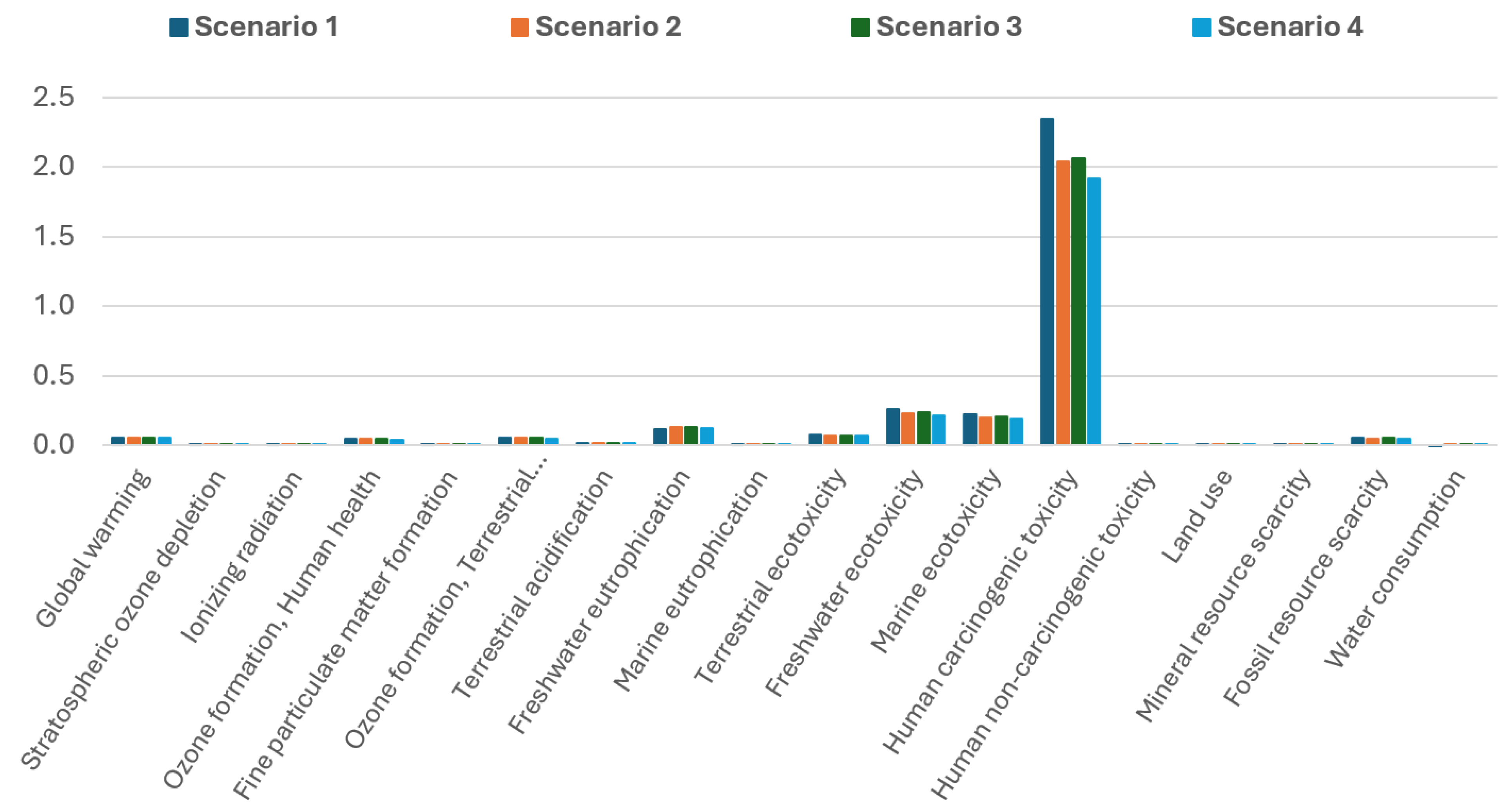
Figure 15 presents normalised midpoint results, highlighting the most critical environmental impacts associated with mortar production. The most dominant impact categories identified from the results include human carcinogenic toxicity, freshwater ecotoxicity, marine ecotoxicity, freshwater eutrophication, and global warming potential. These impacts represent the highest environmental burdens in the conventional mix (S1) and are therefore used as the primary basis for evaluating the performance of the alternative mixes in S2, S3, and S4.
Figure 16 shows the characterised midpoint results as percentage differences in those environmental impacts for S2, S3, and S4 relative to S1, with S1 serving as the baseline, while Table 6 presents the relevant midpoint results. When 60% of virgin sand was replaced with <4.75 mm GFA in S2, modest improvements were observed in most key impact areas. Human carcinogenic toxicity decreased by approximately 13%, which can be attributed to the reduced demand for natural raw materials and the utilisation of recycled glass that carries lower upstream emissions. Similarly, freshwater and marine ecotoxicity declined by around 7% to 13%, indicating that the environmental load from waste glass processing is lower than that associated with river sand extraction. A slight reduction in global warming potential was also observed (0.4% lower than S1), reflecting the avoided emissions from waste glass landfilling. However, freshwater eutrophication increased by about 8%, likely due to the water used in cleaning and processing the GFA. Overall, S2 delivered environmental benefits in most categories, though some trade-offs emerged.
Further refining GFA to a size below 1.18 mm (S3) led to less favourable outcomes. According to the waste recycling facility iQRenew, further crushing glass below 1.18 mm requires an additional drying step, as screening particles smaller than 2 mm becomes difficult without it. This additional energy required for drying increased the environmental burden in several categories. Fossil resource scarcity was the most affected, increasing by 4.5% compared to S2, which had previously shown a 2.9% reduction compared to S1. Global warming and terrestrial ecotoxicity followed, rising by 1.3% and 1.4% over S2, respectively. All other impact categories also showed slight worsening in S3 compared to S2. These results indicate that reducing GFA size to below 1.18 mm introduces additional environmental burdens that diminish the gains achieved through partial sand replacement by <4.75 mm GFA.
In S4, where 10% of OPC was replaced with FA alongside 60% GFA, significant improvements were observed across all high-impact categories. Human carcinogenic toxicity showed the most substantial reduction, decreasing by 18.2% compared to S1, due to the lower emissions associated with FA production and the reduced clinker content. Freshwater and marine ecotoxicity decreased by 16.4% and 15.5%, respectively, reflecting the dual benefit of reduced emissions and enhanced matrix densification from the pozzolanic activity of FA. Importantly, freshwater eutrophication, which had increased in both S2 and S3, was brought back below the baseline level in S4, with only a 2.4% increase over S1. This indicates that FA replacement not only compensates for the environmental costs of GFA processing but also contributes additional significant sustainability gains. Global warming potential also dropped substantially, with an 18% reduction compared to the control, reaffirming the advantage of reducing clinker usage in cementitious materials.
The results for water consumption require careful interpretation, particularly in S1, where a negative value is reported. This anomaly arises from the Ecoinvent database’s modelling of glass landfilling, which accounts for the capture of landfill leachate that is directed to wastewater treatment. As a result, the system assigns a net negative water use to S1, which does not reflect actual water savings but rather a modelling artefact. In contrast, Scenarios 2, 3, and 4 show small positive water consumption values, mainly due to the washing and processing of GFA. Despite this, water use remains low in absolute terms and is not among the most critical impact categories. On the other hand, land use shows a clear environmental benefit in all GFA-containing scenarios. The use of recycled glass reduces dependence on virgin sand extraction and, more importantly, avoids the need for landfilling glass waste. As a result, land use impacts are reduced by 42% in S2 and S3, and by 47% in S4 compared to S1, reinforcing the resource conservation and circular economy advantages of GFA utilisation in mortar production.
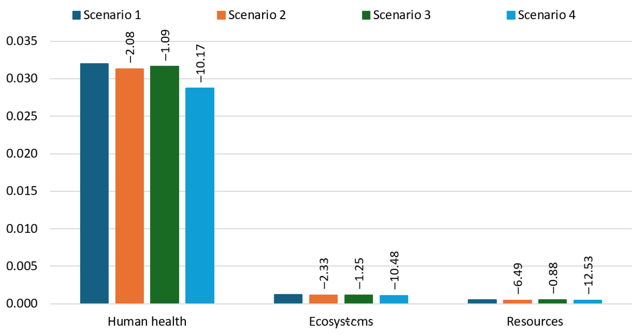
Figure 17 presents the normalised endpoint results, summarising the overall environmental burden of each scenario across three damage categories: Human Health, Ecosystems, and Resources. These results provide a high-level interpretation of the environmental trade-offs and benefits associated with the substitution of conventional materials with GFA and FA. In the Human Health category, S2 and S3 show very limited improvements over S1, with percentage reductions of only 2.08% and 1.09%, respectively.
This indicates that replacing 60% of river sand with GFA, whether at <4.75 mm or <1.18 mm, offers only marginal health-related environmental benefits when OPC content remains unchanged. In contrast, S4, which combines GFA with 10% FA replacement for OPC, shows a significant reduction of 18.26% in human health-related impacts. This demonstrates that FA plays a critical role in reducing emissions and pollutants associated with clinker production, which are major contributors to human toxicity, particulate matter formation, and related health risks. The Ecosystems category follows a similar trend. S2 and S3 provide minimal improvements (2.33% and 1.25% reductions, respectively), whereas S4 shows a substantial 18.62% decrease. This reflects the contribution of FA to lowering acidification, eutrophication, and ecotoxicity-related burdens, which directly affect terrestrial and aquatic ecosystems. The low improvement seen in S3 also confirms that the environmental cost of processing <1.18 mm GFA offsets its marginal benefits in this category. In the Resources category, the benefits of FA replacement are again evident. While S2 and S3 reduce resource-related impacts by only 6.49% and 0.88%, respectively, S4 achieves a significant 18.56% reduction. This is due to reduced demand for clinker and virgin sand, both of which are resource-intensive. The near-neutral result for S3 is a direct consequence of the increased energy demand associated with drying fine GFA, which diminishes its resource efficiency.
Table 7 presents the cumulative energy demand for each scenario across various impact categories, while Figure 18 illustrates the total energy demand per scenario. The total energy demand for producing 1 m3 of mortar varies notably across the four scenarios. S1, representing conventional mortar with 100% OPC and river sand, has the highest energy demand at 2572.3 MJ, serving as the baseline. Replacing 60% of river sand with <4.75 mm GFA in S2 results in a slight reduction, bringing the total energy use down to 2503.2 MJ, a 2.7% decrease compared to S1. However, further reducing the GFA size to <1.18 mm in S3 increases the total energy demand to 2611.1 MJ, which is 1.5% higher than in S1. This increase is due to the additional drying step required for <1.18 mm GFA processing. In contrast, S4, which combines 60% GFA with 10% FA replacement for OPC, achieves the most significant reduction in total energy demand, dropping to 2151.5 MJ. This represents a 16.4% decrease from the baseline, highlighting the energy-saving potential of incorporating FA as a partial cement replacement. These results demonstrate that while the use of GFA alone offers modest benefits, combining GFA with FA delivers substantial energy efficiency in mortar production.

3.5. Multidimensional Evaluation of Performance, Environmental Impact, and Cost

A more detailed comparison of all scenarios reveals the full extent of the trade-offs between technical performance, environmental performance, and material cost. While <1.18 mm GFA demonstrated slightly better technical performance in terms of ASR mitigation (0.07% expansion vs. 0.20% with <4.75 mm GFA) and higher long-term compressive strength (40 MPa vs. 37 MPa with <4.75 mm GFA), these gains came at a disproportionate cost. Environmentally, <1.18 mm GFA failed to improve key midpoint categories beyond what was achieved with <4.75 mm GFA and, in several cases, performed worse. Environmental impacts such as fossil resource scarcity, global warming, and terrestrial ecotoxicity increased by 4.5%, 1.3%, and 1.4%, respectively, primarily due to the additional drying process required for producing <1.18 mm GFA. Total energy demand increased by 1.5% over conventional mortar and 4.3% over <1.18 mm GFA mortar, further confirming the inefficiency introduced by <1.18 mm GFA processing. Moreover, according to iQRenew, the additional drying step required to produce <1.18 mm GFA significantly increases production costs. While the cost of producing 4.75 mm GFA is approximately 1.95 AUD per tonne, the cost rises to 3.15 AUD per tonne for <1.18 mm GFA, representing a 62% increase. This added expense introduces a clear economic disadvantage to the use of <1.18 mm GFA in mortar production.
However, the FA inclusion showed the most balanced performance overall. The addition of 10% FA to the <4.75 mm GFA mix led to a 16.4% reduction in energy demand compared to conventional mortar and yielded significant environmental gains, including an 18% decrease in global warming potential and reductions of 18.2%, 16.4%, and 15.5% in carcinogenic toxicity, freshwater ecotoxicity, and marine ecotoxicity, respectively. Endpoint results also confirmed that FA utilisation reduced human health, ecosystem, and resource-related impacts by 18.2%, 18.6%, and 18.6%, respectively. These findings demonstrate that while utilising <1.18 mm GFA offers incremental technical gains, these are outweighed by its increased environmental and economic burdens. In contrast, FA inclusion not only enhances durability and energy efficiency but also provides a substantially more sustainable and economically viable solution for mortar production when used with <4.75 mm GFA.

4. Conclusions

This study investigated the effects of GFA particle size and FA incorporation on the mechanical performance, ASR resistance, and environmental impact of mortar. Both experimental testing and life cycle assessment were conducted to evaluate the trade-offs between technical performance and sustainability. The following conclusions summarise the key findings and practical implications of the research.
  • Workability improves with larger GFA (<4.75 and 1.18–4.75 mm) due to its smooth surfaces, while finer GFA (<1.18 mm) provides minimal enhancement. The inclusion of FA further increases flowability owing to its spherical particle shape, making it beneficial for workability improvement.
  • ASR expansion is highly dependent on GFA size, with larger particles causing severe expansion, while finer GFA (<1.18 mm) reduces expansion but remains above safe limits at higher replacement levels. The inclusion of FA effectively suppresses ASR, with even a 10% replacement of OPC proving sufficient to reduce expansion below the threshold, making FA a highly efficient mitigation strategy in GFA-based mortar.
  • Larger GFA particles (<4.75 and 1.18–4.75 mm) reduce compressive strength more significantly due to poor bonding and segregation, while finer GFA (<1.18 mm) leads to long-term strength gain through pozzolanic activity despite early-age reductions. The inclusion of FA causes initial strength loss but enables partial recovery over time, with 10% FA showing the best balance between ASR mitigation and strength.
  • Replacing 60% of river sand with GFA moderately reduces environmental impacts, particularly in toxicity-related categories, but also introduces trade-offs such as increased freshwater eutrophication. Reducing GFA size to <1.18 mm provides minimal additional environmental benefit and instead increases total energy demand and processing-related impacts due to the energy-intensive drying step. In contrast, incorporating FA with GFA results in the most substantial environmental improvements across all impact categories, including significant reductions in global warming potential, toxicity, eutrophication, land use, and energy demand. These findings confirm that while the use of <4.75 mm GFA alone offers limited benefits, combining GFA with FA maximises sustainability gains in mortar production.
  • Although reducing GFA particle size improves both compressive strength and ASR resistance, the additional processing required introduces significant environmental and energy burdens. Considering the overall sustainability performance, the use of <4.75 mm GFA combined with just 10% FA provides the most balanced solution, effectively mitigating ASR while minimising environmental impacts and preserving material efficiency in mortar production.
These findings offer practical guidance for developing more sustainable construction materials by leveraging locally available waste resources. The results support the advancement of circular economy practices in the construction sector by demonstrating how combining GFA with FA can reduce dependence on virgin materials and lower the environmental footprint of cement-based composites.
Future research should build on this multidimensional assessment by extending the investigation from mortar to concrete and structural-scale elements. This would allow for the evaluation of ASR mitigation, strength development, and environmental performance under conditions that more closely resemble real-world construction. Scaling up the study will help capture effects related to aggregate gradation, volume stability, and long-term durability that may not be apparent in mortar. In addition, assessing the performance of GFA-FA systems under exposure conditions such as carbonation, chloride ingress, and thermal cycling would provide further insights into their applicability for sustainable infrastructure.

Author Contributions

Conceptualization, V.F., W.L. and C.G.; Data curation, V.F.; Formal analysis, V.F.; Funding acquisition, W.L. and H.W.; Investigation, V.F.; Methodology, W.L., H.S., H.W. and C.G.; Project administration, W.L.; Resources, W.L. and H.S.; Supervision, W.L., H.W. and C.G.; Validation, W.L., H.S., H.W. and C.G.; Writing—original draft, V.F.; Writing—review and editing, W.L., H.S., H.W. and C.G. All authors have read and agreed to the published version of the manuscript.

Funding

This project is funded by ARC-ITRH (Australian Research Council-Industrial Transformation Research Hub) research grant (IH200100010) allocated for Transformation of Reclaimed Waste Resources to Engineered Materials and Solutions for a Circular Economy (TREMS).

Data Availability Statement

The raw data supporting the conclusions of this article will be made available by the authors on request.

Acknowledgments

The first author gratefully acknowledges the financial support provided by the University of Southern Queensland and the Centre for Future Materials through the UniSQ International Stipend Research Scholarship (via TREMS) and the UniSQ International Fees Research Scholarship.

Conflicts of Interest

The authors declare no conflicts of interest.

References

  1. U.S. Environmental Protection Agency. Environmental Factoids. 2016. Available online: https://archive.epa.gov/epawaste/conserve/smm/wastewise/web/html/factoid.html (accessed on 2 July 2025).
  2. Eid, J. Glass is the hidden gem in a carbon-neutral future. Nature 2021, 599, 7. [Google Scholar] [CrossRef]
  3. Topçu, I.B.; Canbaz, M. Properties of Concrete Containing Waste Glass. Cem. Concr. Res. 2004, 34, 267–274. [Google Scholar] [CrossRef]
  4. Guo, P.; Meng, W.; Nassif, H.; Gou, H.; Bao, Y. New Perspectives on Recycling Waste Glass in Manufacturing Concrete for Sustainable Civil Infrastructure. Constr. Build. Mater. 2020, 257, 119579. [Google Scholar] [CrossRef]
  5. Olofinnade, O.M.; Ndambuki, J.M.; Ede, A.N.; Booth, C. Application of Waste Glass Powder as a Partial Cement Substitute towards More Sustainable Concrete Production. Int. J. Eng. Res. Afr. 2017, 31, 77–93. [Google Scholar] [CrossRef]
  6. Washington Recycling Development Center. Glass Recycling; Washington Recycling Development Center: Washington, DC, USA, 2021. [Google Scholar]
  7. Federico, L.M.; Chidiac, S.E. Waste Glass as a Supplementary Cementitious Material in Concrete—Critical Review of Treatment Methods. Cem. Concr. Compos. 2009, 31, 606–610. [Google Scholar] [CrossRef]
  8. Mohajerani, A.; Vajna, J.; Cheung, T.H.H.; Kurmus, H.; Arulrajah, A.; Horpibulsuk, S. Practical Recycling Applications of Crushed Waste Glass in Construction Materials: A Review. Constr. Build. Mater. 2017, 156, 443–467. [Google Scholar] [CrossRef]
  9. Ali, E.E.; Al-Tersawy, S.H. Recycled Glass as a Partial Replacement for Fine Aggregate in Self Compacting Concrete. Constr. Build. Mater. 2012, 35, 785–791. [Google Scholar] [CrossRef]
  10. Rajabipour, F.; Giannini, E.; Dunant, C.; Ideker, J.H.; Thomas, M.D.A. Alkali–Silica Reaction: Current Understanding of the Reaction Mechanisms and the Knowledge Gaps. Cem. Concr. Res. 2015, 76, 130–146. [Google Scholar] [CrossRef]
  11. Du, H.; Tan, K.H. Effect of Particle Size on Alkali-Silica Reaction in Recycled Glass Mortars. Constr. Build. Mater. 2014, 66, 275–285. [Google Scholar] [CrossRef]
  12. Johnston, C.D. Waste Glass as Coarse Aggregate for Concrete. J. Test. Eval. 1974, 2, 344–350. [Google Scholar] [CrossRef]
  13. Pike, R.G.; Hubbard, D. Physicochemical Studies of the Destructive Alkali-Aggregate Reaction in Concrete. J. Res. Natl. Bur. Stand. 1957, 59, 127–132. [Google Scholar] [CrossRef]
  14. Abdallah, S.; Fan, M. Characteristics of Concrete with Waste Glass as Fine Aggregate Replacement. Int. J. Eng. Technol. Res. 2014, 2, 11–17. [Google Scholar]
  15. Ismail, Z.Z.; AL-Hashmi, E.A. Recycling of Waste Glass as a Partial Replacement for Fine Aggregate in Concrete. Waste Manag. 2009, 29, 655–659. [Google Scholar] [CrossRef]
  16. Takata, R.; Sato, S.; Nonaka, T.; Ogata, H.; Hattori, K. Investigation on Alkali–Silica Reaction Utilizing Waste Glass in Concrete and Suppression Effect by Natural Zeolite. In Proceedings of the 29th Conference on Our World in Concrete and Structures, Singapore, 25–26 August 2004; p. 26. [Google Scholar]
  17. Idir, R.; Cyr, M.; Tagnit-Hamou, A. Use of Fine Glass as ASR Inhibitor in Glass Aggregate Mortars. Constr. Build. Mater. 2010, 24, 1309–1312. [Google Scholar] [CrossRef]
  18. Kim, J.; Yi, C.; Zi, G. Waste Glass Sludge as a Partial Cement Replacement in Mortar. Constr. Build. Mater. 2015, 75, 242–246. [Google Scholar] [CrossRef]
  19. Pereira De Oliveira, L.A.; Castro-Gomes, J.P.; Santos, P. Mechanical and Durability Properties of Concrete with Ground Waste Glass Sand. In Proceedings of the 11 DBMC International Conference on Durability of Building Materials and Components, Istanbul, Turkey, 11–14 May 2008. [Google Scholar]
  20. Topçu, I.B.; Boǧa, A.R.; Bilir, T. Alkali-Silica Reactions of Mortars Produced by Using Waste Glass as Fine Aggregate and Admixtures Such as Fly Ash and Li2CO3. Waste Manag. 2008, 28, 878–884. [Google Scholar] [CrossRef]
  21. Taha, B.; Nounu, G. Properties of Concrete Contains Mixed Colour Waste Recycled Glass as Sand and Cement Replacement. Constr. Build. Mater. 2008, 22, 713–720. [Google Scholar] [CrossRef]
  22. Borhan, T.M. Properties of Glass Concrete Reinforced with Short Basalt Fibre. Mater. Des. 2012, 42, 265–271. [Google Scholar] [CrossRef]
  23. Batayneh, M.; Marie, I.; Asi, I. Use of Selected Waste Materials in Concrete Mixes. Waste Manag. 2007, 27, 1870–1876. [Google Scholar] [CrossRef]
  24. Rahim, N.L.; Che Amat, R.; Ibrahim, N.M.; Salehuddin, S.; Mohammed, S.A.; Abdul Rahim, M. Utilization of Recycled Glass Waste as Partial Replacement of Fine Aggregate in Concrete Production. Mater. Sci. Forum 2015, 803, 16–20. [Google Scholar] [CrossRef]
  25. Malik, M.I.; Bashir, M.; Ahmad, S.; Tariq, T.; Chowdhary, U. Study of Concrete Involving Use of Waste Glass as Partial Replacement of Fine Aggregates. IOSR J. Eng. 2013, 3, 8–13. [Google Scholar] [CrossRef]
  26. Malik, M.I.; Manzoor, A.; Ali, R.; Ahmad, B.; Asima, S.; Bashir, M. Positive Potential of Partial Replacement of Fine Aggregates By Waste Glass (<600 Micron). Int. J. Civ. Eng. Technol. 2014, 5, 146–153. [Google Scholar]
  27. Limbachiya, M.C. Bulk Engineering and Durability Properties of Washed Glass Sand Concrete. Constr. Build. Mater. 2009, 23, 1078–1083. [Google Scholar] [CrossRef]
  28. De Castro, S.; De Brito, J. Evaluation of the Durability of Concrete Made with Crushed Glass Aggregates. J. Clean. Prod. 2013, 41, 7–14. [Google Scholar] [CrossRef]
  29. Zeybek, Ö.; Başaran, B.; Aksoylu, C.; Karalar, M.; Althaqafi, E.; Beskopylny, A.N.; Stel’makh, S.A.; Shcherban, E.M.; Umiye, O.A.; Özkılıç, Y.O. Shear Performance in Reinforced Concrete Beams with Partial Aggregate Substitution Using Waste Glass: A Comparative Analysis via Digital Imaging Processing and a Theoretical Approach. ACS Omega 2024, 9, 41662–41675. [Google Scholar] [CrossRef]
  30. Karalar, M.; Başaran, B.; Aksoylu, C.; Zeybek, Ö.; Althaqafi, E.; Beskopylny, A.N.; Stel’makh, S.A.; Shcherban’, E.M.; Umiye, O.A.; Özkılıç, Y.O. Utilizing Recycled Glass Powder in Reinforced Concrete Beams: Comparison of Shear Performance. Sci. Rep. 2025, 15, 6919. [Google Scholar] [CrossRef]
  31. Jin, Z.; Liang, K.; Liu, C.; Yang, G.; Cui, K.; Mao, S. Mechanical Properties and Life Cycle Assessment (LCA) of Waste Glass Reinforced Concrete. J. Build. Eng. 2024, 96, 110643. [Google Scholar] [CrossRef]
  32. Onyelowe, K.C.; Ebid, A.M.; Riofrio, A.; Soleymani, A.; Baykara, H.; Kontoni, D.-P.N.; Mahdi, H.A.; Jahangir, H. Global Warming Potential-Based Life Cycle Assessment and Optimization of the Compressive Strength of Fly Ash-Silica Fume Concrete; Environmental Impact Consideration. Front. Built Environ. 2022, 8, 1–15. [Google Scholar] [CrossRef]
  33. ASTM C33/C33M; Standard Specification for Concrete Aggregates—Annual Book of ASTM Standards. ASTM International: Philadelphia, PA, USA, 2023.
  34. ASTM C566; Standard Test Method for Total Evaporable Moisture Content of Aggregate by Drying—Annual Book of ASTM Standards. ASTM International: Philadelphia, PA, USA, 2023.
  35. ASTM C128; Standard Test Method for Relative Gravity (Specific Gravity) and Absorption of Fine Aggregate—Annual Book of ASTM Standards. ASTM International: Philadelphia, PA, USA, 2022.
  36. Torres-Carrasco, M.; Palomo, J.G.; Puertas, F. Sodium Silicate Solutions from Dissolution of Glasswastes. Stat. Anal. Mater. Constr. 2014, 64, e014. [Google Scholar] [CrossRef]
  37. Ellerbrock, R.; Stein, M.; Schaller, J. Comparing Amorphous Silica, Short-Range-Ordered Silicates and Silicic Acid Species by FTIR. Sci. Rep. 2022, 12, 11708. [Google Scholar] [CrossRef]
  38. dos Santos, V.H.J.M.; Pontin, D.; Ponzi, G.G.D.; de Guimarães e Stepanha, A.S.; Martel, R.B.; Schütz, M.K.; Einloft, S.M.O.; Dalla Vecchia, F. Application of Fourier Transform Infrared Spectroscopy (FTIR) Coupled with Multivariate Regression for Calcium Carbonate (CaCO3) Quantification in Cement. Constr. Build. Mater. 2021, 313, 125413. [Google Scholar] [CrossRef]
  39. Yusuf, M.O. Bond Characterization in Cementitious Material Binders Using Fourier-Transform Infrared Spectroscopy. Appl. Sci. 2023, 13, 3353. [Google Scholar] [CrossRef]
  40. American Coal Ash Association. Fly Ash Facts for Highway Engineers; American Coal Ash Association: Aurora, CO, USA, 2003. [Google Scholar]
  41. Shehata, M.H.; Thomas, M.D.A. Effect of Fly Ash Composition on the Expansion of Concrete Due to Alkali-Silica Reaction. Cem. Concr. Res. 2000, 30, 1063–1072. [Google Scholar] [CrossRef]
  42. ASTM C1437; Standard Test Method for Flow of Hydraulic Cement Mortar—Annual Book of ASTM Standards. ASTM International: Philadelphia, PA, USA, 2020. [CrossRef]
  43. ASTM C1260; Standard Test Method for Potential Alkali Reactivity of Aggregates (Mortar-Bar Method)—Annual Book of ASTM Standards. ASTM International: Philadelphia, PA, USA, 2023.
  44. ASTM C1567; Standard Test Method for Determining the Potential Alkali-Silica Reactivity of Combinations of Cementitious Materials and Aggregate (Accelerated Mortar-Bar Method)—Annual Book of ASTM Standards. ASTM International: Philadelphia, PA, USA, 2023.
  45. ASTM C109/C109M; Standard Test Method for Compressive Strength of Hydraulic Cement Mortars (Using 2-in. or [50 Mm] Cube Specimens)—Annual Book of ASTM Standards. ASTM International: Philadelphia, PA, USA, 2021.
  46. AS ISO 14044; Environmental Management—Life Cycle Assessment—Requirements and Guidelines. Standards Australia: Sydney, Australia, 2019.
  47. AS ISO 14040; Environmental Management—Life Cycle Assessment—Principles and Framework. Standards Australia: Sydney, Australia, 2019.
  48. Hossain, M.U.; Poon, C.S.; Lo, I.M.C.; Cheng, J.C.P. Comparative Environmental Evaluation of Aggregate Production from Recycled Waste Materials and Virgin Sources by LCA. Resour. Conserv. Recycl. 2016, 109, 67–77. [Google Scholar] [CrossRef]
  49. Advanced Readymix Environmental Product Declaration “S25/20/CLR” Concrete, Manufactured at Seven Hills. 2024. Available online: https://epd-australasia.com/wp-content/uploads/2024/11/EPD-IES-0013988-001-ARM-Seven-Hills_S25-20-CLR.pdf (accessed on 6 February 2025).
  50. Tushar, Q.; Salehi, S.; Santos, J.; Zhang, G.; Bhuiyan, M.A.; Arashpour, M.; Giustozzi, F. Application of Recycled Crushed Glass in Road Pavements and Pipeline Bedding: An Integrated Environmental Evaluation Using LCA. Sci. Total Environ. 2023, 881, 163488. [Google Scholar] [CrossRef]
  51. Rajabipour, F.; Maraghechi, H.; Fischer, G. Investigating the Alkali-Silica Reaction of Recycled Glass Aggregates in Concrete Materials. J. Mater. Civ. Eng. 2010, 22, 1201–1208. [Google Scholar] [CrossRef]
  52. Yuksel, C.; Ahari, R.S.; Ahari, B.A.; Ramyar, K. Evaluation of Three Test Methods for Determining the Alkali-Silica Reactivity of Glass Aggregate. Cem. Concr. Compos. 2013, 38, 57–64. [Google Scholar] [CrossRef]
  53. Liu, Z.; Shi, C.; Shi, Q.; Tan, X.; Meng, W. Recycling Waste Glass Aggregate in Concrete: Mitigation of Alkali-Silica Reaction (ASR) by Carbonation Curing. J. Clean. Prod. 2022, 370, 133545. [Google Scholar] [CrossRef]
  54. Maraghechi, H.; Shafaatian, S.M.H.; Fischer, G.; Rajabipour, F. The Role of Residual Cracks on Alkali Silica Reactivity of Recycled Glass Aggregates. Cem. Concr. Compos. 2012, 34, 41–47. [Google Scholar] [CrossRef]
  55. Bleszynski, R.F.; Thomas, M.D.A. Microstructural Studies of Alkali-Silica Reaction in Fly Ash Concrete Immersed in Alkaline Solutions. Adv. Cem. Based Mater. 1998, 7, 66–78. [Google Scholar] [CrossRef]
  56. Hong, S.-Y.; Glasser, F.P. Alkali Binding in Cement Pastes: Part I. The C-S-H Phase. Cem. Concr. Res. 1999, 29, 1893–1903. [Google Scholar] [CrossRef]
  57. Hong, S.-Y.; Glasser, F.P. Alkali Sorption by C-S-H and C-A-S-H Gels: Part II. Role of Alumina. Cem. Concr. Res. 2002, 32, 1101–1111. [Google Scholar] [CrossRef]
  58. Fernando, W.C.V.; Lokuge, W.; Wang, H.; Gunasekara, C.; Dhasindrakrishna, K. Sustainable Mortar with Waste Glass Fine Aggregates and Pond Ash as an Alkali-Silica Reaction Suppressor. Case Stud. Constr. Mater. 2025, 22, e04269. [Google Scholar] [CrossRef]
  59. Chen, C.H.; Huang, R.; Wu, J.K.; Yang, C.C. Waste E-Glass Particles Used in Cementitious Mixtures. Cem. Concr. Res. 2006, 36, 449–456. [Google Scholar] [CrossRef]
  60. Polley, C.; Cramer, S.M.; de la Cruz, R.V. Potential for Using Waste Glass in Portland Cement Concrete. J. Mater. Civ. Eng. 1998, 10, 210–219. [Google Scholar] [CrossRef]
  61. Afshinnia, K.; Rangaraju, P.R. Mitigating Alkali-Silica Reaction in Concrete: Effectiveness of Ground Glass Powder from Recycled Glass. Transp. Res. Rec. 2015, 2508, 65–72. [Google Scholar] [CrossRef]
  62. Aliabdo, A.A.; Abd Elmoaty, A.E.M.; Aboshama, A.Y. Utilization of Waste Glass Powder in the Production of Cement and Concrete. Constr. Build. Mater. 2016, 124, 866–877. [Google Scholar] [CrossRef]
  63. Saha, A.K. Effect of Class F Fly Ash on the Durability Properties of Concrete. Sustain. Environ. Res. 2018, 28, 25–31. [Google Scholar] [CrossRef]
  64. Plowman, C.; Cabrera, J.G. The Use of Fly Ash to Improve the Sulphate Resistance of Concrete. Waste Manag. 1996, 16, 145–149. [Google Scholar] [CrossRef]
  65. Hay, R.; Ostertag, C.P. New Insights into the Role of Fly Ash in Mitigating Alkali-Silica Reaction (ASR) in Concrete. Cem. Concr. Res. 2021, 144, 106440. [Google Scholar] [CrossRef]
Figure 1. Materials used: (a) <4.75 mm GFA; (b) 1.18–4.75 mm GFA; (c) <1.18 mm GFA; (d) OPC; (e) Fly Ash.
Recycling 10 00133 g001
Figure 2. Size distribution of different size ranges of GFAs and sand.
Recycling 10 00133 g002
Figure 3. SEM images of (a) sand and (b) GFA.
Recycling 10 00133 g003
Figure 4. SEM images of (a) OPC and (b) FA.
Recycling 10 00133 g004
Figure 5. FTIR spectra for (a) sand and GFA; (b) OPC and FA.
Recycling 10 00133 g005
Figure 6. Specimen preparation and testing: (a) mixing of mortar; (b) flow table; (c) preparation of prism specimens for ASR expansion test; (d) measuring ASR expansion using vertical comparator; (e) mortar cube testing setup.
Recycling 10 00133 g006
Figure 7. System boundary and framework.
Recycling 10 00133 g007
Figure 8. Flow test results for (a) 4.75 mm GFA mixes with varying GFA and FA; (b) varying GFA size and percentage.
Recycling 10 00133 g008
Figure 9. AMBT ASR expansion results for (a) increasing <4.75 GFA; (b) increasing 1.18–4.75 GFA; (c) increasing <1.18 GFA; (d) <4.75 GFA and 10% FA; (e) <4.75 GFA and 20% FA; (f) <4.75 GFA and 30% FA.
Recycling 10 00133 g009
Figure 10. SEM images of (a) control mortar and (b) mortar with 20% FA.
Recycling 10 00133 g010
Figure 11. Compressive strength results of mixes with increasing GFA content and varying GFA sizes: (a) at 28 days; (b) at 91 days.
Recycling 10 00133 g011
Figure 12. Cross-sections of mortar specimens with 100% GFA: (a) <4.75 mm; (b) <1.18 mm; (c) 1.18–4.75 mm; (d) <4.75 mm with 30% FA.
Recycling 10 00133 g012
Figure 13. SEM images of (a) 28-day mortar with 100% GFA; (b) 91-day mortar with 100% GFA.
Recycling 10 00133 g013
Figure 14. Compressive strength of <4.75 mm GFA mixes with varying FA content: (a) at 28 days; (b) at 91 days.
Recycling 10 00133 g014
Figure 15. Normalised ReCiPe 2016 midpoint results.
Recycling 10 00133 g015
Figure 16. Comparison of characterised ReCiPe 2016 midpoint results.
Recycling 10 00133 g016
Figure 17. Normalised endpoint results.
Recycling 10 00133 g017
Figure 18. Total energy demand.
Recycling 10 00133 g018
Table 1. Properties of GFA and river sand.
PropertyGFASand
<4.75<1.181.18−4.75
Moisture content (%)0.120.180.083.9
Water absorption (%)0.300.320.220.48
Density (kg/m3)25022627
Table 2. Chemical compositions of OPC and FA.
MaterialComposition (%)
Al2O3BaOCaOCr2O3Fe2O3K2OMgOMnONa2OP2O5SO3SiO2SrOTiO2LOI
OPC4.270.03>600.023.390.613.350.240.120.142.8619.50.070.232.85
FA25.020.14.560.016.90.881.290.090.30.610.2556.280.051.342.17
Table 3. Mix ratios.
Mix DesignationCement/Binder (kg/m3)Fine Aggregate (kg/m3)
OPCFly AshFly Ash %SandGFAGFA %
0FA0GFA466--58100
20GFA466--46511620
40GFA466--34923240
60GFA466--23234960
80GFA466--11646580
100GFA466--0581100
10FA0GFA419471058100
20GFA419471046511620
40GFA419471034923240
60GFA419471023234960
80GFA419471011646580
100GFA41947100581100
20FA0GFA373932058100
20GFA373932046511620
40GFA373932034923240
60GFA373932023234960
80GFA373932011646580
100GFA37393200581100
30FA0GFA3261403058100
20GFA3261403046511620
40GFA3261403034923240
60GFA3261403023234960
80GFA3261403011646580
100GFA326140300581100
Table 4. Raw material sources and distances to the beam casting site.
MaterialsProducersDistance (km)
CementWagners Cement Plant, Pinkenba54
SandCarbrook River Sand Facility44
GravelKeperra quarry facility37.6
Fly ashMillmerran power station217
GFAFrom the Willawong waste collection facility to the Wacol glass recycling facility11
Wacol glass recycling facility11.2
Table 5. Material inputs.
InputsReference S1S2S3S4
WaterTap water {RoW}|tap water production, conventional treatment|Cut-off, Ukg205205205205
CementCement, Portland {RoW}|cement production, Portland|Cut-off, Ukg466466466419.4
Transport, freight, lorry 16–32 metric tonne, EURO4 {RoW}|market for transport, freight, lorry 16–32 metric tonne, EURO4|Cut-off, Utkm25.1625.1625.1622.65
Fly ashFly ashkg 46.6
Transport, freight, lorry 16–32 metric tonne, EURO4 {RoW}|market for transport, freight, lorry 16–32 metric tonne, EURO4|Cut-off, Utkm 10.11
SandSand {RoW}|gravel and sand quarry operation|Cut-off, Ukg581232.4232.4232.4
Transport, freight, lorry 7.5–16 metric tonne, EURO4 {RoW}|market for transport, freight, lorry 7.5–16 metric tonne, EURO4|Cut-off, Utkm25.5610.2310.2310.23
GFAWashing waste glass (Sizes varying from 0.75–150 mm)—Tap water {RoW}|tap water production, conventional treatment|Cut-off, U—water 50 kg/t—Tushar et al. [50]kg/t 348.6348.6348.6
Processing waste glass to produce < 5 mm GFA—47 MJ/t (electricity) and 21 MJ/t (diesel)—Hossain et al. [48]MJ/t
Processing waste glass to produce < 1 mm GFA—An additional 7.83 m3 of natural gas (iQRenew)MJ/t 233
Landfilling waste glass—Waste glass {GLO}|treatment of waste glass, sanitary landfill|Cut-off, Ukg348.6
Transport, freight, lorry 7.5–16 metric tonne, EURO4 {RoW}|market for transport, freight, lorry 7.5–16 metric tonne, EURO4|Cut-off, Utkm 7.747.747.74
Mixing17 kWh per 1 m3 of concrete (Jin et al. [31])—Electricity, medium voltage {AU}|market for electricity, medium voltage|Cut-off, UkWh17171717
Table 6. Characterised ReCiPe 2016 midpoint results.
Impact categoryUnitS1S2S3S4
Global warmingkg CO2 eq4.7 × 1024.6 × 1024.7 × 1024.2 × 102
Stratospheric ozone depletionkg CFC11 eq4.1 × 10−54.2 × 10−54.3 × 10−54.1 × 10⁻⁵
Ionizing radiationkBq Co−60 eq2.9 × 1002.9 × 1002.9 × 1002.6 × 100
Ozone formation, Human healthkg NOx eq9.9 × 10−19.6 × 10−19.6 × 10−18.8 × 10⁻¹
Fine particulate matter formationkg PM2.5 eq3.3 × 10−13.3 × 10−13.3 × 10−13.0 × 10⁻¹
Ozone formation, Terrestrial ecosystemskg NOx eq1.0 × 1009.7 × 10−19.8 × 10−19.0 × 10−1
Terrestrial acidificationkg SO2 eq8.1 × 10−18.0 × 10−18.0 × 10−17.3 × 10⁻¹
Freshwater eutrophicationkg P eq7.8 × 10−28.4 × 10−28.4 × 10−28.0 × 10⁻²
Marine eutrophicationkg N eq4.9 × 10−35.2 × 10−35.3 × 10−34.9 × 10⁻³
Terrestrial ecotoxicitykg 1,4−DCB1.2 × 1031.1 × 1031.1 × 1031.1 × 103
Freshwater ecotoxicitykg 1,4−DCB6.6 × 1005.9 × 1005.9 × 1005.5 × 100
Marine ecotoxicitykg 1,4−DCB9.8 × 1008.9 × 1008.9 × 1008.3 × 100
Human carcinogenic toxicitykg 1,4−DCB2.4 × 1012.1 × 1012.1 × 1012.0 × 101
Human non-carcinogenic toxicitykg 1,4−DCB2.0 × 1021.9 × 1021.9 × 1021.8 × 102
Land usem2a crop eq1.3 × 1017.7 × 1007.7 × 1007.4 × 100
Mineral resource scarcitykg Cu eq1.8 × 1001.7 × 1001.7 × 1001.6 × 100
Fossil resource scarcitykg oil eq5.3 × 1015.1 × 1015.3 × 1014.8 × 101
Water consumptionm3−3.2 × 10−19.2 × 10−19.2 × 10−18.7 × 10−1
Table 7. Cumulative energy demand for each scenario.
Impact CategoryUnitS1S2S3S4
Non-renewable, fossilMJ2.4 × 1032.3 × 1032.4 × 1032.0 × 103
Non-renewable, nuclearMJ5.4 × 1015.3 × 1015.3 × 1014.4 × 101
Non-renewable, biomassMJ9.2 × 10−28.3 × 10−28.3 × 10−27.4 × 10⁻²
Renewable, biomassMJ3.8 × 1013.8 × 1013.8 × 1013.1 × 101
Renewable, wind, solar, geothermalMJ2.5 × 1012.7 × 1012.7 × 1012.3 × 101
Renewable, waterMJ5.5 × 1015.6 × 1015.6 × 1014.6 × 101
Disclaimer/Publisher’s Note: The statements, opinions and data contained in all publications are solely those of the individual author(s) and contributor(s) and not of MDPI and/or the editor(s). MDPI and/or the editor(s) disclaim responsibility for any injury to people or property resulting from any ideas, methods, instructions or products referred to in the content.

