Article

Conceptual Recycling Chain for Proton Exchange Membrane Water Electrolyzers—Case Study Involving Review-Derived Model Stack

1
Institute for Mechanical Process Engineering and Mineral Processing, TU Bergakademie Freiberg, Agricolastr. 1, 09599 Freiberg, Germany
2
WBK Institute of Production Science, KIT Karlsruhe Institute of Technology, Kaiserstraße 12, 76131 Karlsruhe, Germany
3
Helmholtz-Zentrum Dresden-Rossendorf, Helmholtz Institute Freiberg for Resource Technology, Chemnitzer Straße 40, 09599 Freiberg, Germany
4
IME Process Metallurgy and Metal Recycling, RWTH Aachen University, Intzestraße 3, 52056 Aachen, Germany
5
Heraeus Precious Metals GmbH & Co., KG, Heraeusstr. 12-14, 63450 Hanau, Germany
*
Authors to whom correspondence should be addressed.
Recycling 2025, 10(3), 121; https://doi.org/10.3390/recycling10030121
Submission received: 25 April 2025 / Revised: 2 June 2025 / Accepted: 11 June 2025 / Published: 19 June 2025

Abstract

:
The recycling of proton exchange membrane water electrolyzer (PEMWE) raw materials is imperative due to their scarcity, cost, complexity and environmental impact. This is particularly true in the context of expanding electrolyzer manufacturing and reducing production costs. Developing comprehensive recycling strategies requires the creation of a model stack due to the diversity in stack design, structure and materials. The review-derived model presented here provides a sound basis and summarizes the variety of approaches found in the literature and industry. The holistically developed recycling chain, including dismantling, mechanical processing, hydrometallurgical processes and carbon reuse, is characterized by the complete recycling of materials, the reduced application of energy-intensive process steps and the avoidance of environmentally harmful processes. Emphasis is placed on demonstrating the non-destructive disassembly of joined components, the dry mechanical decoating of catalyst-coated membranes, membrane dissolution, the separation of anode and cathode particles and the environmentally friendly hydrometallurgical processing of platinum.

1. Introduction

Green hydrogen is seen as an essential building block for sector coupling and paves the way for new decarbonization paths. Such sectors where CO2 generation is difficult to abate include, for example, refining, aviation, shipping and road transport, iron and steel production, the cement industry, the chemical industry and the generation of high-temperature industrial heat [1]. Green hydrogen is considered inevitable in those sectors. To produce the large quantities of green hydrogen required for the decarbonization of these sectors, the technology of water electrolysis must be scaled up. Water electrolysis is considered as the central and so far the most promising technology for clean, CO2-neutral, i.e., green, hydrogen production [2]. As an important water electrolysis technology, proton exchange membrane (PEM) electrolysis is expected to grow strongly in the market due to its good load change behavior and possible operation in the partial load range. Compared to other technologies, it can respond more quickly to fluctuating electricity supplies, e.g., from renewable sources.
As the capacity of electrolyzer installations expands, the recovery and recycling of critical raw materials used in PEM water electrolyzers (PEMWEs), such as iridium and platinum, will become increasingly important in the future. The criticality of these raw materials [3]—stemming from supply security concerns, resource availability and sustainability considerations associated with hydrogen technology—drives the need to develop an adapted circular economy for PEMWE stacks.
According to the International Energy Agency (IEA), global electrolysis capacity for hydrogen production has grown in recent years, reaching an installed capacity of 1.4 GW by the end of 2023 [4]. The production capacity of electrolyzers at that time reached 25 GW per year. The electrolysis capacity is increasing from a low starting point and must be significantly accelerated to align with the Net Zero Emissions by 2050 (NZE) scenario. This scenario requires the installation of 560 GW of electrolysis capacity by 2030 [4]. The increasing demand for electrolyzers with a simultaneously constant production volume of only approx. 8 tons of iridium per year worldwide illustrates the importance of an efficient recycling chain.
As no standard PEMWE stack design has yet been established in the industry or research, a huge variety of technological designs are available [5,6,7,8,9,10]. Due to this high diversity, the development of suitable recycling approaches becomes more challenging as an adequate recycling concept must be tailored. Currently, the limited number of circular economy strategies for PEMWE stacks discussed so far focuses primarily on the hydrometallurgical and pyrometallurgical recovery of noble metals [11]; any other materials are not the focus.
A recycling approach which combines automated disassembly and mechanical processing can increase the maturity of the recovered materials and enable further circular economy strategies such as the reuse, repair or remanufacturing of selected components. These strategies are more environmentally friendly due to their low energy consumption, avoidance of fluorine emissions and possibility to recover membrane and carbon materials. However, mechanical recycling approaches for PEMWEs have not been designed and introduced on a large scale so far.
In order to advance research on recycling processes, a PEMWE model stack defined to represent a potential scaled-up stack is described as a starting point for further investigations. For this purpose, the components are described individually based on the literature and evaluated with respect to recycling strategies. This is followed by a general overview of relevant recycling stages in different areas of the circular economy. Finally, the integrated mechanical and metallurgical process chain for the recycling of PEMWE is described, and quantitative results for individual process steps are presented.

2. Model Stack of Proton Exchange Membrane Water Electrolyzer

The development of new or adapted recycling technologies needs a defined and representative material as a starting point. Due to the high diversity of PEMWE stacks [5,6,7,8,9,10], however, this representativity is not yet a given, which is why a conceptual outline of a stack based on the literature is worked out here to illustrate the potential material flows in the recycling streams. For this purpose, the individual components first have to be examined with regard to their relevance for recycling. Then the various configurations are assessed in terms of their likelihood of use on the basis of component requirements and market penetration. To understand the individual components, first the stack structure and the principle of operation are described. A possible model stack is shown in Figure 1.
The electrochemical cell of the electrolyzer consists of a polymer electrolyte membrane (PEM—proton exchange membrane) and the electrodes applied to it. This composite structure is the core element of the electrolyzer and is called a catalyst-coated membrane (CCM) or a membrane electrode assembly (MEA). This is where the electrochemical conversion of water to hydrogen and oxygen takes place, with hydrogen ions, i.e., protons, serving as charge carriers. On both sides of the CCM there are porous transport layers (PTLs), which are also called gas diffusion layers (GDLs), on the cathode side and liquid–gas diffusion layers (LGDLs) on the anode side. During operation, water and the product gases flow through these layers. They also contribute to closing the electrical circuit. Bipolar plates (BPPs), which ensure the inflow and outflow of reactants and products as well as the overall mechanical stability of the cell and close the circuit as current collectors, complete the repeating unit on both sides. Since the hydrogen production rate of one electrochemical cell is limited, multiple repeating units are combined into a stack to increase the overall power uptake and performance of the electrolyzer. The stack is framed by two massive end plates, which ensure proper sealing due to the uniform pressure distribution between layers in the repeating units. The compression derives from a tensioning system such as tie rods and screws. In order to apply an electrical current to the stack, one current distributor plate is used at each end of the stack between the multiple repeating units and end plates [12]. In addition, gaskets inside the stack provide an additional sealing functionality and equilibrate tolerances that may occur during operation.
Looking at the scientific literature [5,6,7,8,9,10] and the commercially available stack components on the market [13,14,15,16,17,18,19,20], differences in the characteristics and properties of the respective components are evident. The large number of variants of PEMWE stacks is clearly illustrated in a so-called morphological box in Table 1. The individual components, their properties and their different characteristics are described in detail below. The characteristics marked in bold in the morphological box are those commonly used.

2.1. Catalyst-Coated Membrane

For recycling, the mechanical properties and the recyclable material content are of primary importance, as they have a major influence on the recycling approach. Since the critical raw materials, such as precious metals, are mainly contained in the electrodes, which form the special composite structure of the catalyst-coated membrane (CCM), this component is considered first. In addition to the CCM, there are other types of MEA designs, such as porous transport electrodes (PTEs), where the catalyst is applied directly to the porous transport layers. Since the production and structure of CCMs differ from those of PTEs [21], a different recycling approach is required for the latter. For this reason, and because CCMs are used almost exclusively, PTEs are not considered further in this study.

2.1.1. Anode

The layered material composite must meet the highest requirements for mechanical and chemical stability and for electrochemical functionality. For this purpose, highly stable and electrochemically active materials are used to withstand the harsh operating conditions. On the anode side in particular, the high electrode potentials and the oxygen generated lead to corrosive conditions, which means that only certain precious metals can be used as catalysts. Because of its suitable catalytic activity and high corrosion resistance, iridium is mainly used in its pure form, as iridium black, mixed-metal form or oxide form for oxygen evolution reactions [6,22]. Ruthenium, by contrast, has better catalytic properties but is not stable enough in the long term under the conditions mentioned above [23]. Since iridium has a very low market availability and is much more costly, mixed oxides of iridium and ruthenium are also used, which are a compromise between stability, activity and price [23]. The use of iridium–ruthenium oxide mixture reduces material availability problems for large-scale production.
Another way avoiding the material scarcity and high production costs of PEMWEs is to reduce the iridium content in the anode, which is one main current focuses in electrode development [24,25]. Iridium loading can thus be reduced from 1–3 mgIr cm−2, which describes the state of the art, to, e.g., 0.3 mgIr cm−2 without causing performance losses [26]. Also, an ultra-low iridium loading of, for example, 0.08 mgIr cm−2 is another research focus [27]. These low loadings are made possible either by very thin electrode layers or by carrier materials such as titanium oxide [28]. Nevertheless, in industry and most of the literature, state-of-the-art anodes are made of non-supported iridium oxide with a loading of 1–3 mg cm−2 [29]. Hence, recycling strategies should firstly be adapted to this reference iridium content.
The catalyst material discussed so far has a typical particle size of approximately 2 nm and it is embedded in a binder/carrier system [27]. Since the binder, composed of the same ionomers as the proton exchange membrane, is an electrical insulator but also contributes to the mechanical stability and the dimensional stability of the structure, the ionomer content should be optimized to maintain all these functionalities, prioritizing uniform current distribution in the anode, which is essential for the electrochemical reaction. Contents of 5 to 33 wt% ionomer are commonly discussed in the literature [5,7,30,31]. For a low iridium loading on the anode side, Su et al. [30] reported an optimal ionomer content of 5 wt%, while Xu and Scott [32] described an optimal content of 25 wt%.
The thickness of the anode layer strongly depends on the iridium loading, ionomer content and catalyst support. In the literature, the thickness varies between 2 and 12 µm [8,10,26,27,31,33], with Bernt et al. [34] describing the best cell performance for a thickness of 4 to 8 µm, equivalent to 1–2 mgIr cm−2. A thickness of 3 to 4 µm has been reported for a lower loading of 0.34 mgIr cm−2 by Padgett et al. [35].
For these aforementioned parameters it is not possible to define exact values due to the high geometrical diversity, so recycling strategies have to address these types of variations. Given that iridium is one of the most valuable materials utilized in PEMWEs [3], the objective is to ensure its complete recovery without any losses. This encompasses the separation of the electrode from the membrane, followed by the subsequent metallurgical processing steps.

2.1.2. Cathode

The cathode layer, which is deposited on the opposite side of the proton exchange membrane, has a very similar structure. Commercially available catalyst materials, such as platinum on a carbon support, can be used because this layer does not have to withstand the harsh conditions of the anode. In PEM fuel cells (PEMFCs), carbon-supported platinum has also been widely applied. In addition to platinum, palladium is also a suitable catalyst for the hydrogen evolution reaction [9]. Palladium is also used as a carbon-supported catalyst [8], which is currently a focus of research [6]. However, palladium shows a slightly lower electrochemical performance than platinum [36], and the cost advantages of palladium as previously described [6,37] are no longer applicable in the context of the current raw material prices (Q1/2025). Since 2019, the price of Pd has been significantly higher than that of Pt; by early 2024, the raw material prices of platinum and palladium had converged [38].
The 8 to 21 µm thick layer [10,26,27,34] of the cathode consists of the catalyst, which is usually applied to a porous carbon support to minimize the platinum loading and to increase overall catalytic active area. Typically, a ratio of 40 to 60 ma.% metallic platinum is used as a catalyst on industrial carbon black or on other carbon supports, such as carbon nanotubes (CNTs). A very common support material is Vulcan XC72 from Cabot Corporation, since it is also used a lot in PEMFCs. Likewise, TEC10V50E from Tanaka Precious Metals Group Co., Japan [14], with a platinum ratio of approx. 46%, which was developed for PEMFCs, is often applied as a catalyst powder [7]. Since the platinum content, its particle size and local distribution within the CCM at the End of Life (EoL) are affected by degradation and dispersion phenomena [27], the initial ratio of platinum to carbon it is not relevant for the selection of recycling strategies.
Starting from the raw material, the platinum loading amounts to 0.5–1.0 mgPt cm−2 [5,6], which has already been reduced to 0.1–0.3 mgPt cm−2 in current research [27,39,40]. Analogous to the anode, a binder with mass fractions of 20–30% [5,31] is again used to ensure stability and proton transport.
As the recycling of platinum and/or palladium catalysts represents the current state of the art in PEMFC recycling [41], the metallurgical recovery of these precious metals from the cathode will not present a significant challenge. In addition to the goal of recycling the cathode without dissolving the precious metals, i.e., directly recycling the components, the objective is to identify a more environmentally sustainable approach that does not require the use of highly corrosive chemicals. In the context of mechanical recycling, the layer structure represents the most significant factor.

2.1.3. Membrane

The name-giving core element of a PEMWE is the proton exchange membrane, also called the polymer electrolyte membrane. It fulfills the functions of a reactant barrier to avoid gas permeation, an electrical insulator between the electrodes to avoid a short circuit and a proton conductor to close the electric circuit via charge carriers. In addition, it provides mechanical stability for the electrodes, which are commonly applied to the membrane. Considering the harsh electrochemical operating conditions, the material also has to demonstrate a low gas permeability at high pressures and excellent chemical stability [5,8,42].
Based on these requirements, only certain materials are eligible for proton exchange membrane, and perfluorosulfonic acid (PFSA) is the most outstanding. Looking at the structure of the polymer, the polytetrafluoroethylene (PTFE) backbone provides a high mechanical, thermal and chemical robustness, whereas its high proton conductivity is triggered by the perfluorinated side chains in the polymer ending with a hydrophilic sulfonic acid group [43]. Initially, PFSA was used because it was also applied in PEMFCs and was readily available with various membrane thicknesses of 51 to 254 µm depending on the supplier [19]. Thereupon it was established as an electrolyzer material despite some serious disadvantages.
On the one hand, the high costs in production and in disposal originate from the fluorochemistry applied here. Perflourinated hydrocarbons are stable in the long term and accumulate in the environment [44]. They have already been detected in drinking water and are suspected of causing damage to health [44]. In cases of pyrometallurgical treatment for the recovery of platinum-group metals, it is particularly important to neutralize evolved toxic gases, e.g., hydrogen fluoride [45,46,47]. On the other hand, at temperatures above 80 °C the membrane loses its mechanical integrity and emits water, leading to a decrease in ionic conductivity [45]. This temperature dependency restricts the window of operation of PEMWEs. Furthermore, the membrane becomes permeable for gas especially at increased temperatures and high pressures, leading to specific safety risks due to explosive gas mixtures of hydrogen and oxygen. In order to avoid this, thick membranes are utilized, resulting in high resistance to proton transport [48] and an increase in ohmic losses [31,49]. PFSA membranes exhibit hygroscopic behavior, expanding and contracting with humidity and temperature fluctuations [50].
The best-known brand name for PFSA membranes is Nafion® from Chemours (formerly DuPont). It was widely used in PEMFCs and has also established its use in electrolyzers [45,51]. Besides long-side-chain (LSC) PFSA products, like Nafion®, Aciplex® and Fumion®, there are also short-side-chain (SSC) PFSA products, differing in essential properties. Aquivion®, developed by Solvay Solexis, is the best-known SSC-PFSA and can provide improved thermal stability, resulting in a higher degree of crystallinity and higher thermal transition temperatures [52]. In addition to PFSA-only membranes, there are composite membranes that are mechanically reinforced with another polymer such as PEEK (polyether ether ketone) or PTFE. Fumatech offers reinforced and non-reinforced membranes made of LSC- and SSC-PFSA in thicknesses of 60 to 150 µm [18]. W. L. Gore & Associates, Inc. also offers an ePTFE-reinforced PEM with a thickness of 80 µm [16], which promises low gas permeability, a wide operating range and a more compact electrolyzer due to its reduced thickness.
Apart from PFSA, hydrocarbon membranes, i.e., sulfonated poly (ether ether ketone) and sulfonated polybenzimidazole, have also been the subject of research for some time, as they have low production costs and, even more importantly, do not require fluorine chemistry [45]. Some investigations were also carried out for their use in PEMFCs, but they could not compete against Nafion® in particular due to their short lifetime [43]. As well, in PEMWEs, the hydrocarbon membranes show advantageous behavior, such as low gas crossover despite operation at high pressures and good thermal stability [45].
Since the membrane is the core of the MEA and provides mechanical stability, it is also of great interest for recycling. Due to the variety of membranes and the differences in mechanical properties, one recycling strategy will probably not fit all types. Thus, it is important to focus on the most commonly used materials and develop the strategy on that. Nafion® is predominantly used both in research and on the market, mostly limited to Nafion® N115 and N117 [9,33,49] with thicknesses of 127 and 178 µm. Over the past two decades, the trend in fuel cells has been towards thinner membranes [51]. It can be reasonably assumed that this development will also be seen in the future for electrolyzers. CCM manufacturers and some of the literature [45] refer to N115 as the state of the art; therefore, this paper also uses this type as the model membrane.
Since the PFSA in CCMs releases toxic fluorine gases (especially HF) during metallurgical processing [41,45,46], it is important for environmental reasons to separate as much membrane material as possible from the electrodes before they are submitted to a metallurgical process step. It is also worthwhile to recover PFSA as a product because of its material value [11,22,53], and researchers are ambitiously developing ways to reuse recycled PFSA in CCMs through a recasting process [54,55]. To achieve this, the purest possible PFSA product must be obtained by mechanical methods or by dissolving the membrane.

2.2. Porous Transport Layer

The next functional layer in the electrolyzer is the porous transport layer (PTL), which is applied to the CCM from both sides, i.e., covering both the anode and the cathode side of the CCM. The important properties of the PTL are its electrical conductivity, for contact between the electrode layer and the bipolar plate, and corrosion resistance, especially on the anode side. In addition, this layer is responsible for reactant transport and the mechanical support of the CCM [56,57].
The PTL at the anode side is a liquid–gas diffusion layer (LGDL), since oxygen has to be transported as a product in addition to water as the reactant. The harsh conditions on the anode side again require highly stable materials [58], so titanium is commonly used in various variations. In research, sintered materials made of powder or fibers are mainly used [39,56,59], since small cell areas are involved [42]. For larger areas, titanium is more commonly used in the forms of expanded metal [60], meshes [6,61], felts [39,61], foams [8,58,61] and grids [56]. For long-term stability, the layer can also be coated with iridium [8,39], platinum [8,53] or gold [57,62]. According to the literature, the layer’s thickness is usually between 250 and 500 µm, although thicknesses of up to 2 mm have been reported [5,29,39,57]. Manufacturers like Bekaert offer LGDLs in thicknesses from 100 µm to 2 mm [63], Mott Corporation offers LGDLs in 254 to 3175 µm thickness [15] and GKN Powder Metallurgy GmbH offers, among others, type T3P in a thickness of 1300 µm [64]. A porosity between 30 and 50% is considered optimal [59,65,66]. If this layer does not adhere to the CCM, no further mechanical processing will be required, as the LGDL can be separated already by destacking. Thus, in this case, the LGDL could be sorted for further recycling or reuse. If the LGDL sticks to the CCM due to clamping pressure, the titanium component should be removed from the CCM. During this process, parts of the electrode may adhere to the titanium, which should be removed by cleaning to avoid losses and achieve a high recycling rate.
On the cathode side, the gas diffusion layer (GDL) is made of carbon since there are no special requirements for the material’s durability and stability, except for hydrogen embrittlement for some metals [5]. Similarly to GDLs in PEMFCs, carbon felt, paper and nonwovens are used [11,53]. Predominantly, carbon fiber papers of the trademark Toray® are applied, with thicknesses between 110 and 370 µm, and porosities of 75 to 80%, mostly 78%, are stated [13,67]. Other manufacturers include SGL Carbon SE [20] and Freudenberg SE [17], offering GDLs with thicknesses of 150 to 315 µm. GDLs with a microporous layer (MPL) for reduced electrical resistance and improved mass transport can also be implemented [42,58]. As the GDL is usually bound together with the CCM at the seal and adheres to the CCM due to the clamping pressure, further challenges arise during mechanical processing, such as the liberation and subsequent sorting of the shredded product. If the fibers of the GDL can be obtained by mechanical and hydrometallurgical processes, they can be reused at the end of the process chain, for example, in carbon-bonded alumina [68].

2.3. Membrane Electrode Assembly Configurations

In the context of PEMFCs, there is no uniform definition of the structure or design of MEAs. Ma et al. [50] described a three-layer MEA consisting of a membrane and two catalyst layers (CCMs). In a five-layer MEA, the CCM is framed within subgasket layers. A seven-layer MEA consists of a both-side-subgasketed CCM with anode- and cathode-side GDLs [50]. Some synonyms for subgasket are frame or edge protection. These provide sufficient robustness and mechanical durability to the MEA. Considering sufficient insulation between the anode and cathode, typically, malleable plastics such as PI (polyimide) or PTFE are used [21,69]. The provider CMC Klebetechnik GmbH [70] also offers PEN (polyethylene naphthalate), PEEK and PPS (polyphenylene sulfide) subgasket films for PEMFCs and PEMWEs.
These various MEA configurations are also known for PEMWEs. Bernt, Schröter, Möckl and Gasteiger [7] showed an MEA structure with a single-sided subgasket on the anode side [7]. Mayyas et al. [71] described a structure in which the CCM is enclosed by a frame on both sides at the edge areas. In a study from Stähler and coworkers [69], a 12 μm thick subgasket was used to protect the thin membrane from the sharp edges of the titanium PTL. Holzapfel et al. [21] also specify an MEA structure with a two-sided frame. When using a subgasket, there are several different possible assemblies. Either the CCM is encased in the subgasket and the GDL is then attached to the subgasket, or alternatively, the subgasket can encapsulate both the CCM and the mounted GDL. Subgasket films are typically supplied with adhesive on one side and joined by laminating under pressure and/or heat [70]. Without the use of a subgasket, the seal is located directly between the bipolar plate and the CCM.
The variety of MEA configurations with subgaskets presents a challenge in determining the appropriate process for MEA recycling. In the most straightforward scenario, the absence of a subgasket renders the recycling process unaffected. However, in instances where a subgasket is present, its removal or shredding and sorting are necessary to facilitate the recycling of the remaining MEA components.

2.4. Bipolar Plates

The functions of the BPP in the PEMWE stack is to ensure media transport, electrically contact the PLTs, transfer heat and provide mechanical stability. Currently BPPs are typically made of titanium. Lower-cost materials such as stainless steel, e.g., AISI 304 or 316L, could significantly reduce the overall system cost of an electrolyzer system [72]. Stainless steels are cheaper and easier to machine than titanium, but their main drawback is their corrosion at high chemical overpotential within an oxidative medium [5,9,73]. For this reason, a bipolar plate made of stainless steel must be protected with a highly conductive and corrosion-resistant coating. Highly conductive and corrosion-resistant coatings made of titanium, platinum, niobium, niobium/titanium, gold or iridium can further protect against the corrosive environment [6,8,71,73,74]. Other BPP materials mentioned in the literature include graphite and aluminum [8].
According to Bareiß and coworkers [10], PEMWE BPPs consist of thicker materials than PEMFC BPPs due to the higher operating pressure. They are between 0.3 mm and 3 mm thick [10,75] and can be produced using various manufacturing processes, such as sheet metal forming, destructive milling or plate etching [10]. As stated in a patent, the stack manufacturer Hoeller Electrolyzer GmbH produces bipolar plates by sintering [76].
Regarding the flow field in the bipolar plates, the parallel channel configuration remains the most common design in PEMWEs. The flow field design has to ensure the uniformity of the fluid flow and pressure distribution to enable high-pressure operation and a high current density in the stack. The flow channels are machined or stamped directly on the BPP surface [77]. In addition to this cell design with a BPP with an integrated flow field, Borgardt et al. [78] describe further designs. Alternatively, the cells can also be designed with a BPP without a flow field. In this case, a titanium mesh acts as a PTL to transport the media [77,78], which has implications for the disassembly and handling of the components in recycling processes.
The objective of recycling BPPs is to maintain the titanium within the material cycle. This can be achieved by incorporating the material into titanium recycling or by developing an effective reuse and remanufacturing process.

2.5. Sealing

Gaskets in PEM cells are used to seal the anode and cathode chambers, prevent gas crossover and the escape of water, hydrogen and oxygen, and achieve optimum contact between the components. To fulfill the requirements for the operating conditions in PEMWE stacks, the gaskets must have appropriate mechanical and chemical properties [75]. According to the study by Borgardt and coworkers [78], the optimum clamping pressure for PEMWE stacks amounts to 2.0–3.0 MPa [78]. The gasket materials used to fulfill these requirements are usually FKM, EPDM, silicone and PTFE [7,53,75,79]. Suppliers of PEMWE gaskets include the companies Freudenberg Sealing Technologies and Chemours. The usual material thicknesses amount to between 250 and 1640 µm and depend on the gasket material, the stack design and the operating pressure in the stack [53,75,80]. The gaskets are either directly applied to the BPP or the MEA by dispensing or screen-printing, or are alternatively inserted between the BPP and MEA as injection-molded O-ring gaskets.
Similarly, the situation with the subgaskets of MEAs is analogous to that described above. The more firmly the seal is applied to the MEA, the more effort is required to remove it from the supporting components. This can result in the loss of valuable materials, such as adhering catalysts, and the contamination of the products.

2.6. Clamping System

The clamping system establishes the sealing pressure and the correct distribution of the clamping pressure between the various cell components, which reduces the contact resistance between the interfaces. A high clamping pressure increases the contact area between the BPP and the PTL, which reduces the electrical contact resistance between the elements. The clamping pressure therefore plays an important role in optimizing the performance of the stack [75]. The materials used for end plates should provide high electrical insulation, high thermal conductivity, stability and rigidity, as well as corrosion resistance. To fulfill these requirements, end plates are usually made of aluminum or stainless steel and are regularly several centimeters thick [8,80]. Unlike in PEMFCs, which use tension straps in addition to tie rods [71], PEMWE end plates are bolted together with tie rods for tensioning and compression. The tie rods can be located outside or inside the cell stack and guided through boreholes in the cell components. Compression forces of around 2.5 MPa are mentioned in the literature for PEMWE stacks [75,78]. The specific design and structure of the clamping system and the end plates are of particular importance with regard to disassembly.

2.7. Stack Layout

There are major differences between manufacturers in terms of stack format and size. In principle, a distinction can be made between circular and rectangular stacks. According to a study by Smolinka et al. [81], PEMWE stacks at production scale have a cell area of less than 1 m2 (active area including edge). The further literature and a look at the stacks of various manufacturers such as Siemens Energy, Bosch, H-TEC, HIAT and HOELLER also reveal that the commercial stacks at the moment offer an area per cell of approximately between 0.0025 and 0.7 m2 [82,83,84].
Commercial electrolysis systems, such as that of Siemens Energy, have a power input of 17.5 MW and a hydrogen production of up to 2000 kg per hour. The Siemens system has a modular design and consists of 24 identical and connected electrolysis stacks [85]. Hoeller Electrolyzer GmbH offered three different stack sizes with stack power inputs from 76 kW to 1.4 MW (hydrogen production 34 to 635 kg per day per stack). With dimensions of 85 cm × 100 cm × 153 cm and a power input of 1.25 MW, the Bosch electrolysis stack is designed to produce up to 23 kg of hydrogen per hour [86].

3. Recycling Process

3.1. General Recycling Approaches

Before an item can be recycled, it must be assessed according to the EU Waste Directive of 2008 [87]. This directive defines a five-level waste hierarchy, which begins with preventing an item from becoming waste, for example, by extending its lifetime or reusing it. The next level is preparing for reuse, which involves testing, cleaning and repair. In the case of an electrolyzer, certain components such as the bipolar plates can be removed from the stack, and there are realistic options for their reuse after refurbishment or remanufacturing. The recycling of waste is the next level in the hierarchy and aims to use appropriate processes to reprocess waste into products, materials, or substances that can be used for their original purpose or for other purposes. It is important to recover as much material as possible and maintain material quality as far as possible.
To facilitate reuse and recycling, manufacturers should develop a disassembly-friendly design [88]. As soon as an object is destined for recycling, in order to recover valuable materials, it passes through the four steps of the recycling chain according to Martens and Goldmann [89], depending on the type of waste. The general recycling chain includes the following steps:
  • Collection and pre-sorting;
  • Pretreatment and disassembly;
  • Mechanical and chemical processing;
  • The production of secondary (raw) materials.
These steps have to be adapted to the product that is to be recycled. Kumar [90] suggests a similar term for the processing of e-waste without naming the collection, pre-sorting and pretreatment. For lithium-ion batteries (LIBs), Werner [91] explained the general steps of the recycling chain in his paper as follows: preparation (waste logistics and presorting), pretreatment (dismantling and depollution), processing (liberation and separation), and metallurgy (extraction and recovery).
Since there are certain similarities between LIBs and PEM technologies, e.g., the demountable structure, metal-containing electrodes and layered structure of the entire system, it is reasonable to take a closer look at this recycling chain. Individual steps can then be adopted or adapted.
The first step, i.e., preparation, includes waste logistics and presorting. Already, presorting can be logistically organized according to the fuel cell and hydrogen principle (alkaline, high-temperature and PEM). The further presorting of different PEM technology types accounts for the different components or materials used in each.
For LIBs, pretreatment consists of the dismantling of battery systems and depollution. The latter relates to chemical, electrical and thermal hazards. Depollution would not be necessary for PEMWEs or FCs since there is no residual charge nor any volatile solvents within the EoL set-up. With PEM technologies, disassembly is possible down to the repeating unit or even down to the level of individual components, such as the bipolar plates and MEA [41].
Since no general mechanical recycling route has been defined for PEM technologies yet, only individual steps such as liberation and separation can be named for their processing, which currently is the subject of research [47,92]. Nevertheless, these two steps can provide valuable feed materials for metallurgy. For LIBs, the liberation step may also include thermal pretreatment to decompose the binder in the electrodes to facilitate the decoating of the support structure and the electrode foils, respectively [93,94]. Since in PEM technologies the binder and the membrane are made of the same material, a thermal treatment is not an option to improve the liberation. The membrane would decompose, releasing toxic gases.
Metallurgical processes to produce secondary raw materials that can be returned to the material cycle are the state of the art for PGMs [8,22,47]. For platinum catalysts in particular, established processes can be adopted from the fuel cell industry. It is important to note that most PEMFC recycling has focused on platinum only and not on other valuable materials. In the pyrometallurgical recycling of PEMFCs and PEMWEs, the generation of HF from the decomposition of flour-containing membranes is a major issue [46,47]. Even the use of a threefold excess of the additive CaO was insufficient to bind all the HF produced [46]. This leads to significant challenges in pyrometallurgical recycling, including difficulties in process control, increased corrosion and higher process costs [46,47]. This paper does not go into detail about pyrometallurgical experiments, but focuses on hydrometallurgical approaches.

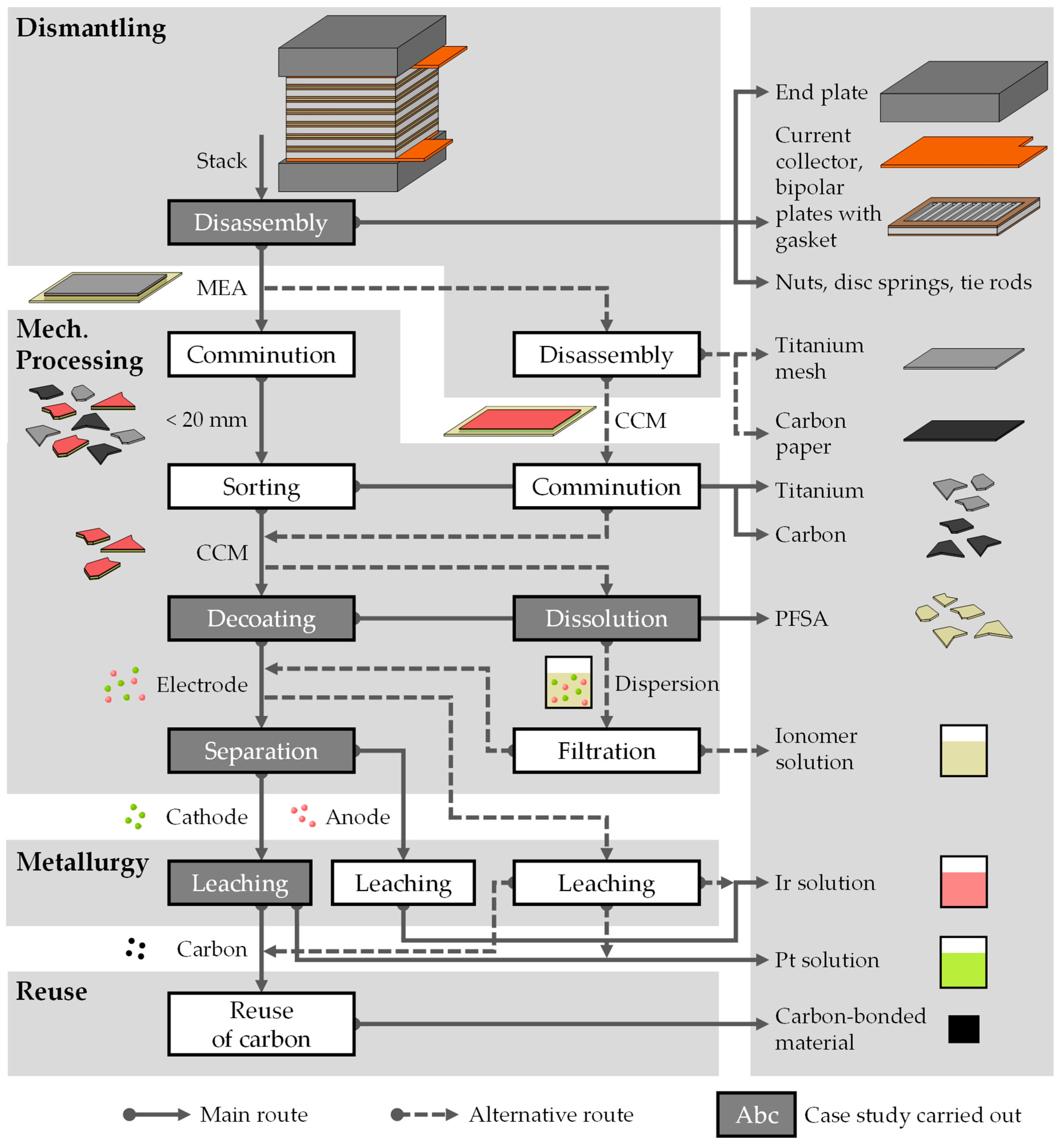
3.2. Process Chain for PEMWE Recycling and Proof of Principle Tests

A conceptual design of a possible process chain for the recycling of PEMWE was developed, which contained some variants (Figure 2). The feed material was the model PEMWE stack as described in Section 1.
First, the end plates, bipolar plates with seals, clamping elements and MEA are demounted through manual or automatic disassembly (see Section 3.2.1). Either a higher dismantling depth is possible and the GDLs and PTLs can be demounted whole, or the MEA has to be shredded into its GDL, PTL and CCM components. The next process sorts the liberated MEA components into their respective fractions. Since the CCM is a composite structure containing critical and valuable target elements, it has to be considered further, and the CCM is cut into smaller, more manageable pieces that can then be fed into the decoating process.
Mechanical decoating, which removes catalyst layers from polymeric membranes, can be performed with an impact stress that liberates both electrode layers from the flexible polymer membrane. The decoating produces a precious-metal-containing electrode powder and a PFSA product of larger decoated membrane pieces (see Section 3.2.2).
Since the electrode powder contains both anode and cathode active materials, a mechanical separation process can be applied to the ultrafine particles to generate a concentrate for the subsequent hydrometallurgical processing (see Section 3.2.4). If a high grade and sufficient recovery cannot be reached with mechanical separation methods, the entire electrode product can be leached as well. Leaching produces a platinum- and iridium-containing solution that can be further hydrometallurgically processed (see Section 3.2.5). Leaching also produces a carbon product from the cathode-side catalyst supports, and this can be processed into carbon-bonded materials in a reuse process.
A variant of the mechanical decoating of CCMs dissolves the membranes in a suitable solvent followed by filtration, and is an alternative approach to separating the electrode material from the fluorinated membrane. The filtration can become challenging, since the particles are below 10 µm in size, leading to a high filtration resistance which leads to a high operation pressure drop. Furthermore, the increase in viscosity due to the dissolved ionomer also effects the pressure drop in the filtration step negatively. The PFSA material from the membrane is recovered as a clear ionomer solution. It may also be useful to dissolve the mechanically decoated membrane pieces, as there may still be electrode residues on, or precious metal particles within, the membrane due to aging effects.

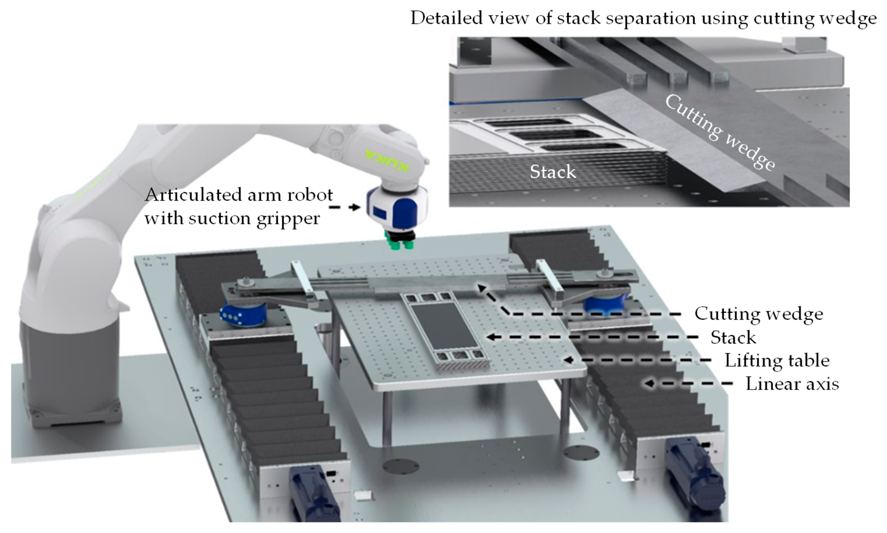
3.2.1. Disassembly into Individual Stack Components

The material-specific separation of products by disassembly has the potential to significantly increase the recycling yield and the grades of the precious and critical metals. Due to its preconcentration, it simplifies the downstream mechanical and metallurgical processing. The repair and reuse of products and the harvesting of components for reuse all require simplified access to product components and their joints. Disassembly thus enables the implementation of these further circular economy strategies [95], and it is of great importance that the disassembly is set up as a non-destructive procedure.
In the paper by Al Assadi et al. [88], the challenges of disassembling PEMFCs have already been highlighted. As fuel cell stacks and electrolysis stacks are comparable in terms of macroscopic product structure, the challenges mentioned can be transferred. A major challenge for disassembly is the adhesion of the stacked layers to each other, which originates from the compression, operation and aging itself, and not primarily from the manufacturing process. It predominantly occurs in the sealing areas between the stacked layers. Furthermore, the accessibility of these joints is also constrained by the layered structure, the small component pitches and the low material thicknesses.
The two main components, the MEA and BPP, exhibit different degradation mechanisms. The typical degradation pathways of the catalyst layer and the membrane are dissolution, poisoning, sintering and catalyst passivation. Degradation of the bipolar plates leads to embrittlement and corrosion [96]. A typical cause of stack failure is the perforation of the MEA [97]. The MEA or the membrane is therefore, in general, the component that limits the lifetime of the stack [10,97,98], while the BPP can have a significantly longer durability.
Mayyas and coworkers [71] provide an overview of the manufacturing cost structure of PEMWE stacks. The largest share of the costs of the CCM or MEA is attributable to material costs such as membrane and PGM costs. In contrast, the material costs for substrate materials and coatings or bipolar plates are low, and the production costs predominate here.
Circular economy strategies can be derived from the duality between MEA and BPP in terms of degradation and cost structure: Given that the MEA is the component that limits the lifetime, and it has a high material value, this component is forwarded for recycling. In order to maintain the high-value-added share of the BPP, its repair or remanufacturing should be realized before recycling [99]. This results in the following requirements for the disassembly process: the non-destructive and sorted disassembly and separation of the components of the PEMWE stack. In the scenario of a repair, it must be possible to separate the stack at any point within the layered construction.
The bonding of the components in an EoL stack is similar to an adhesive bond, which can be released using mechanical, physical or chemical methods [88,100]. Only mechanical methods like cutting, peeling and shearing fulfill the requirements for a non-destructive process if applied to the joints or sealing areas. Physical and chemical processes such as cooling and heating can be used as aids to render the sealing gasket brittle or to exceed its glass transition temperature and thus reduce its strength and the adhesive force. Solvents or blowing fluids can also be used to weaken the adhesion points. The accessibility within the stack structure and the reaction time of the solvent are limiting factors, extending the disassembly process time and generating additional challenges in work and environmental protection.
To demonstrate non-destructive disassembly using a cutting tool and the corresponding equipment required, a mechanical separation process is presented in Figure 3. This process has been validated for fuel cell stacks and could be transferred to electrolysis stacks. The equipment includes a lifting table on which the stack can be adjusted in height. Two linear axes, on which a cutting tool is mounted, can be adjusted synchronously or asynchronously and can guide a wedge through the stack. A robot is used to manipulate the separated components. Using the process described, non-destructive disassembly can be realized.

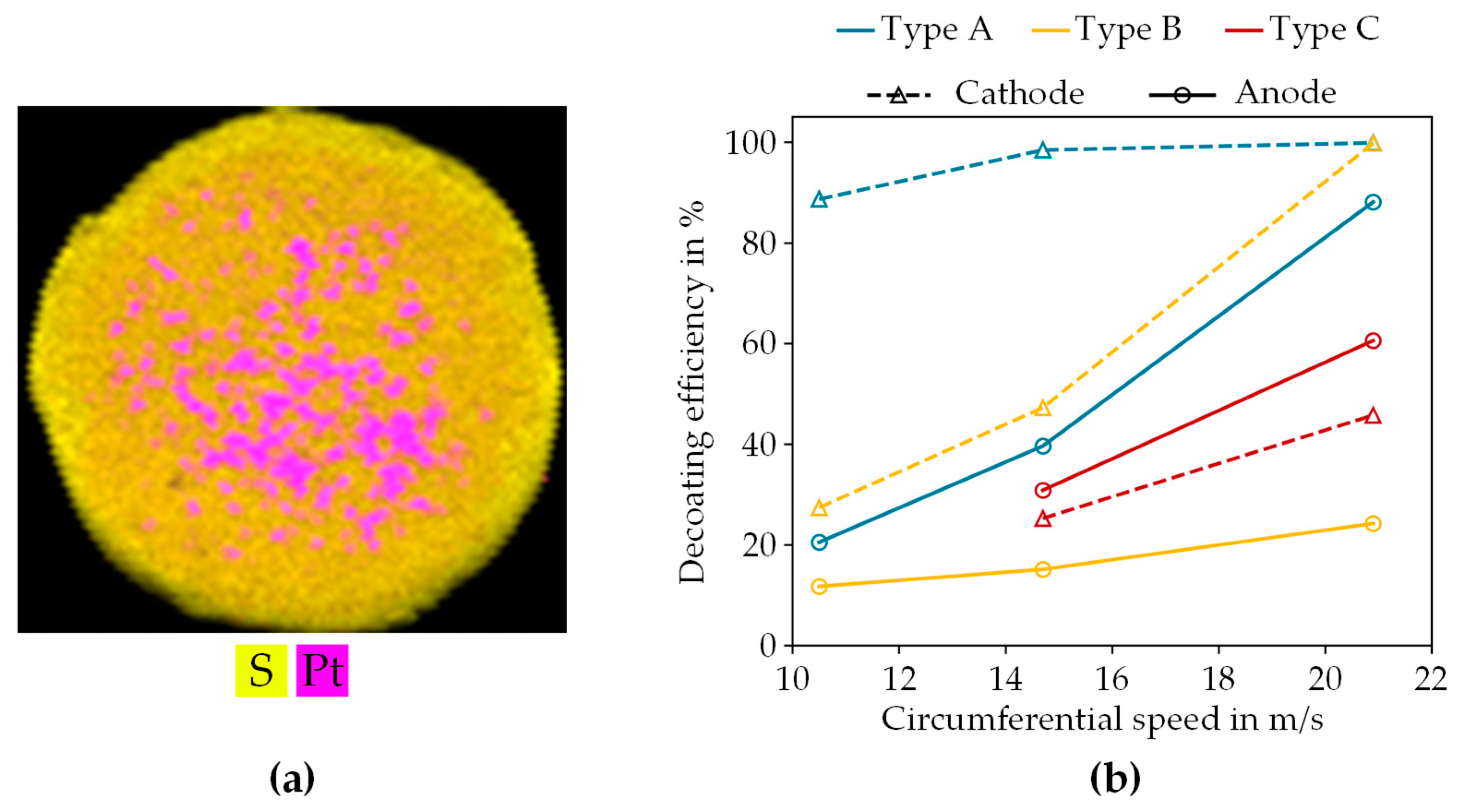
3.2.2. Decoating of Catalyst-Coated Membrane

After the disassembly of the end plates and the separation of the BBP from the MEA, the subsequent step is the decoating of the electrode from the membrane. As it is not clear how the PTL and GDL can be removed, the mechanical decoating focuses on the CCM.
The advantage of mechanically decoating the CCM is that the fluorine-containing membrane is liberated from the valuable electrode materials without the use of solvents or the emission of harmful hydrogen fluoride, which reduces the environmental impact. The membrane material can be recovered as a polymeric material, unlike in hydro- or pyrometallurgy where the membrane is decomposed.
Since the installation of high-capacity electrolyzers is still pending, the actual availability of sample material is limited. Therefore, the experiments were scaled down and a micro-scale hammer mill was used on samples of a size of <100 mg to investigate the separation and liberation of electrodes by mechanical processes. The Picocrush hammer mill with a discharge screen belonging to the Hosokawa Alpine’s Picoline machine platform is the only available comminution machine that can process CCM samples of several millimeters in size in very small quantities. With this machine, samples of less than 100 mg with a diameter of 5 mm can be processed at various speeds, i.e., various specific energy consumption. During this process, the electrode is liberated from the membrane by impact, while the membrane sample remains intact in most cases. It was necessary to develop quantitative analysis methods to meet the requirements set by the small masses and the properties of the samples. The elemental mapping of a µXRF analysis could be used to distinguish the remaining coating and the decoated areas of the CCM based on the dominant elements, which allowed us to quantify the decoating efficiency. For this purpose, iridium and platinum were used as indicators for the anode and cathode, respectively, while areas with a high sulfur content were assumed to be decoated, since the PFSA membrane was directly accessible. An example of such a µXRF mapping is shown in Figure 4a, which illustrates the cathode side of a partially decoated sample.
The investigation results are summarized in Figure 4b for different types of CCM. It shows that with increasing speed, the anode and cathode of each type continue to decoat, and that complete decoating is possible. However, the decoating efficiency, which is the ratio of the decoated area to the total area of the sample, depends on the type of CCM. For instance, type A shows a selective removal of the cathode at lower milling speeds, while the anode is mainly removed at higher speeds. This selective grinding is also CCM-type-dependent. The possible reasons for this include differences in the surface structure of the coating layer, such as cracks in the electrode that facilitate decoating, or the thickness and adhesion of the electrode layer, which are influenced during the manufacturing of the CCM and the binder content. The extent to which the adhesion of the electrodes to the membrane can be influenced prior to decoating remains to be determined in further investigations.
Since the recovery rate of the critical precious metals must be close to 100% for this process step to become relevant, further investigations need to be carried out at higher stressing intensities and higher speeds. Future investigations must also consider different stress mechanisms, combine these with characterizations from material testing (tensile, compression and peel tests) and analyze the failure mechanisms using suitable high-resolution microscopic methods.
If it is not possible to completely decoat the CCM using dry mechanical methods, an alternative process has to be used. This can be a wet mechanical decoating process, for which alcohol treatment has often been used in research to date [53,93], and it must be clarified whether this process can decoat all CCMs in contrast to the dry method. Alternatively, the complete dissolution of the membrane and ionomer-containing binder can be used.

3.2.3. Dissolution of Catalyst-Coated Membrane

An alternative process step to the mechanical decoating of the membrane is the complete dissolution of both the membrane and ionomer-containing binder. The sulfonic-acid-functionalized fluoropolymers (ionomers) that enable proton conductivity through the membrane and the catalyst layers can thus be recovered as a further target material for recycling. It is also an economically relevant target material, since the membranes used in PEMWEs have high costs. A known method for the dissolution of these ionomers is their dispersion in alcohol–water mixtures at high temperatures under pressure [101]. The ionomer dispersion can then be separated from the other components, mainly the catalysts, by filtration or centrifugation. In this work, these procedures were successfully applied to different kinds of CCM. Some obtained precious metal yields are given in Table 2. Analytical methods to determine the ionomer content in the initial CCMs still have to be developed, and the ionomer yield can therefore not yet be given.
The examples show that, within the precision limits of the measurements, losses of platinum and iridium into the ionomer dispersion stream do not occur. In further steps of the downstream processing, the PGM-containing catalyst residue can then be processed by conventional pyro- and hydrometallurgical methods in order to recover the PGMs.
For the ionomer dispersion, further work is necessary in order to evaluate further uses and decide on (direct) recycling or (chemical) downgrading. Knowledge about the chemical integrity of the polymeric ionomers and their impurity profiles is mandatory for this evaluation.

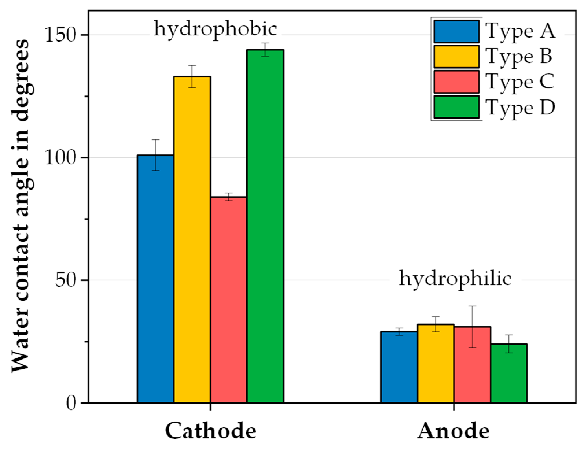
3.2.4. Separation of Anode and Cathode Materials

When the electrode and membrane are separated by one of the aforementioned processes, a mixture of the iridium-containing anode and the platinum-containing cathode is generated. Individual fractions of the two electrode types can be produced for efficient hydrometallurgical processing using mechanical separation processes.
Compared to mechanical separation, chemical methods consume more energy and require an overall higher processing effort. Thus, mechanical processes, which still require fundamental research, may provide an innovative and sustainable technological option to separate ultrafine particles below 10 µm [102,103,104]. Consequently, the development of physical separation processes for PEMWE recycling should be addressed.
As mentioned above, the state-of-the-art materials of the two different electrodes are metal oxides of iridium or ruthenium and platinum on the support material of carbon black. Ahn and Rudolph [105] stated that the catalyst materials used in each electrode of the PEMWE show significant differences in their (de)wetting behavior. The hydrophilic and hydrophobic properties of TiO2 and carbon black, which can be seen as the representative materials of the anode and cathode active materials, reproduce this behavior. The static water contact angle of four different CCM samples was determined with the sessile drop method to confirm the result of the hydrophobic cathode surface in contrast to the hydrophilic anode, as presented in Figure 5. Although the degree of hydrophobicity varies by CCM type, the results are consistent with their work. As described in the discussion of decoating processes, this can also be an effect of the manufacturing process of the CCMs or different binder contents.
To utilize the different wetting properties of TiO2 and carbon black, different methods such as froth flotation or liquid–liquid phase/particle separation (LLPS) can be applied to separate the two representative materials. Froth flotation is the most established separation process, exploiting the different wettability of the particles as the main separation feature. However, the separation of particles below 10 µm in size by flotation is challenging due to the low probability of particle–bubble attachment [106] as well as the entrainment of hydrophilic particles. In a previous study [107], a recovery and grade of 70% and 90% for the representative catalyst particles were achieved through froth flotation. This suggests the need for further improvements. LLPS is presented to overcome the limitation of this conventional separation method [108]. Two immiscible liquid-phase systems allow the transfer of hydrophobic particles to the organic phase while hydrophilic particles remain in the aqueous suspension [109]. Based on LLPS, using a model particle mixture of TiO2 and carbon black, controlling the pH of the initial suspension and the adding of dispersant allowed the recovery of each material to reach 97% and 99%, with grades of 97% and 99%, respectively. TiO2 ended up in the aqueous phase and carbon black in the organic phase, as shown in Figure 6.
However, since amphiphilic ionomers are used as binders during the preparation of catalyst layers, ionomer adsorption on particles may occur, which affects the interaction between the particles and the phase of LLPS and becomes critical to the further design of the separation process. The alignment of ionomer molecules affects the surface properties of electrode powders, especially as the wetting behavior of the anode material changes to water-repelling [110,111].
Furthermore, diversity of the chemical composition and microstructure of proton exchange membranes, such as those based on Nafion, Aquivion, Flemion, or non-fluorinated ionomers, can be considered in further studies. In particular, differences in composition can affect their degradation, and these variations may affect the coated particle properties such as surface charge, wettability and dispersibility [112]. Consequently, they can also impact the separation efficiency.

3.2.5. Leaching of Separated Platinum Catalyst from CCM Material

The next step downstream is the metallurgical processing of the concentrates from mechanical separation, often using a hydrometallurgical approach for the platinum-containing cathode. Precious metals can usually be easily dissolved using highly corrosive chemicals and chemical mixtures such as hydrochloric acid or aqua regia, which is also utilized as one of the primary leaching agents for platinum. Nevertheless, the use of aqua regia raises environmental concerns due to gas formation and its per se corrosive nature. To mitigate environmental concerns, alternative leaching solutions can be employed in the presence of chloride as a platinum complexing agent [113]. A more environmentally friendly platinum extraction process is being investigated by using organic acids, such as acetic and citric acid, with hydrochloric acid [114,115].
The small-scale laboratory leaching experiments were carried out as part of a preliminary study with a synthetic material (platinum on carbon black purchased from Sigma-Aldrich (CAS: 7440-06-4)) which could be one concentrate originating from the mechanical decoating and liquid–liquid separation in the proposed recycling chain for PEMWEs (Section 3.2.4). The leaching results shown here are intended to provide an initial orientation and assessment of the use of oxidizing agents and organic acids that still need to be reproduced with further experiments. Varied leaching parameters such as temperature and leaching agents can be taken from Figure 7. Other leaching conditions, such as solid–liquid ratio and stirring speed, were kept constant throughout all the experiments.
The platinum leaching with aqua regia has the highest efficiency, i.e., recovery in the leachate, amounting to >80% regardless of the temperature. The application and needs of oxidizing agents have already been investigated [113]. The three main reactions from aqua regia are as follows [116]:
3 H C l + H N O 3 N O C l + C l 2 H 2 O
C l 2 + H 2 O H C l ( g ) + H C L O
N O C l N O g + C l
It can be deduced from the reaction equations that Cl outgasses from the system over the reaction time as a result of the reactions. As HCl was not continuously added to the system in the experiments, the yield is lower than would be expected with aqua regia. The relevance of oxidizing agents during the leaching of platinum can be seen in Figure 7. Sodium hypochlorite compared to hydrogen peroxide shows a slight additional increase in efficiency. Figure 8 illustrates the leaching efficiencies of platinum using organic acids in combination with hydrochloric acid.
The leaching efficiency of hydrochloric acid increases when it is combined with organic acids. Even if the efficiencies are still very low, at around 40% at 60 °C, using organic acids, first tests using further oxidizing agents as well as salts show a high potential for leaching efficiencies of at least >70%. As higher efficiencies than 99% are the state of the art for platinum leaching, leaching efficiencies higher than 95% should also be targeted for more environmentally friendly leaching agents, aiming in particular at sustainability and process intensification, but these require further investigation and up-scaling.
After leaching, the liquid phase is separated from the insoluble carbon residue by filtration. The dissolved platinum can be recovered from the solution and the (re)use of the remaining carbon with residual platinum must be investigated. The optimization of leaching and acid recycling will involve the optimization of the filtration and washing steps as well [117,118].

4. Conclusions

Due to the wide range of different PEMWE stack designs, it is challenging to focus on one single technological concept for recycling. Therefore, the whole variety of designs in the literature was presented in a morphological box, and based on a literature review, the relevant characteristics for a model stack were defined. In addition, each component was critically accessed regarding its recyclability and target elements.
With the knowledge of the structure of a PEMWE stack from the first part, a conceptual outline of a combined mechanical and hydrometallurgical recycling chain was developed. This includes the dismantling of the stack, followed by mechanical processing, including MEA/CCM shredding, sorting, CCM decoating, CCM dissolution and anode and cathode separation. The precious metals from the catalysts are then recovered hydrometallurgically. Finally, the carbon from the cathode can be reused. The main findings of the individual tests of the processes can be summed up as follows:
  • During disassembly, adhesive joints were found that were not caused by the manufacturing process but by the operation of the electrolyzer at high pressures. These joints can be broken by an automated non-destructive cutting tool.
  • Dry mechanical decoating of the CCM showed that the electrode layers can be liberated from the membrane material by mechanical stress. Depending on the type of CCM and the electrode side, up to 99% decoating efficiency was achieved.
  • Alternatively to mechanical decoating, the membrane coating of the CCM was dissolved at high temperatures and pressures, which enabled us to recover the valuable membrane material as an ionomer dispersion. More than 99% iridium and platinum recovery has been achieved in small-scale experiments.
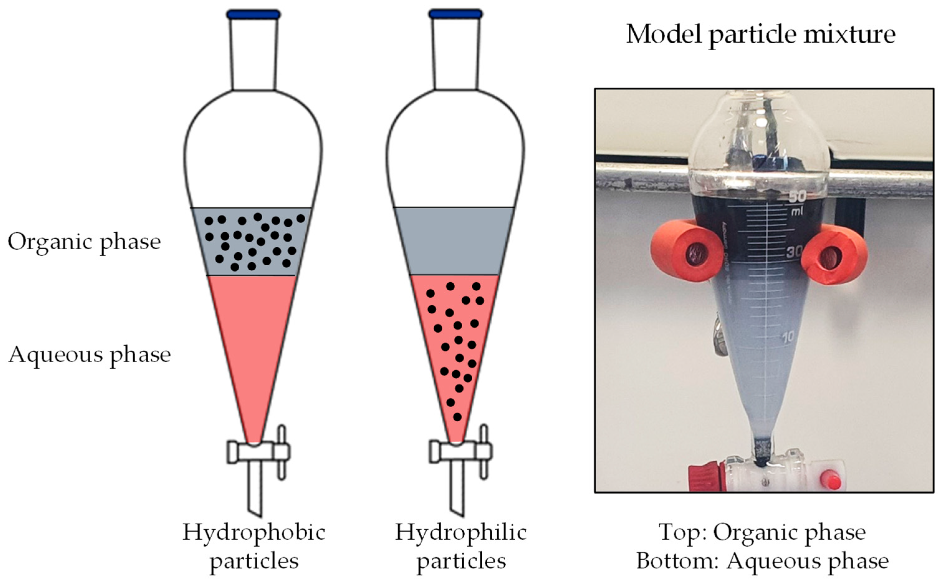
  • A separation process based on the wetting properties of the mixed materials can be used to separate mechanically liberated iridium-containing anode material from the platinum-containing cathode material.
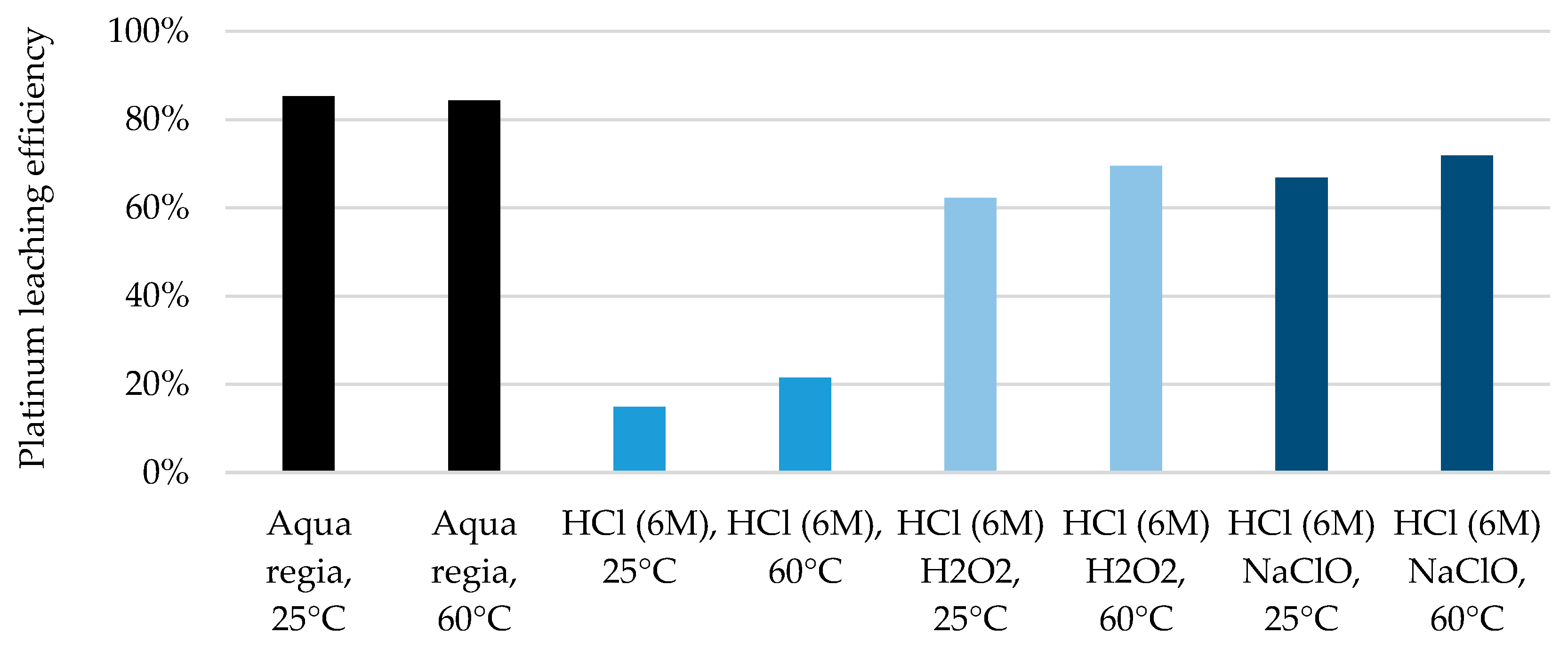
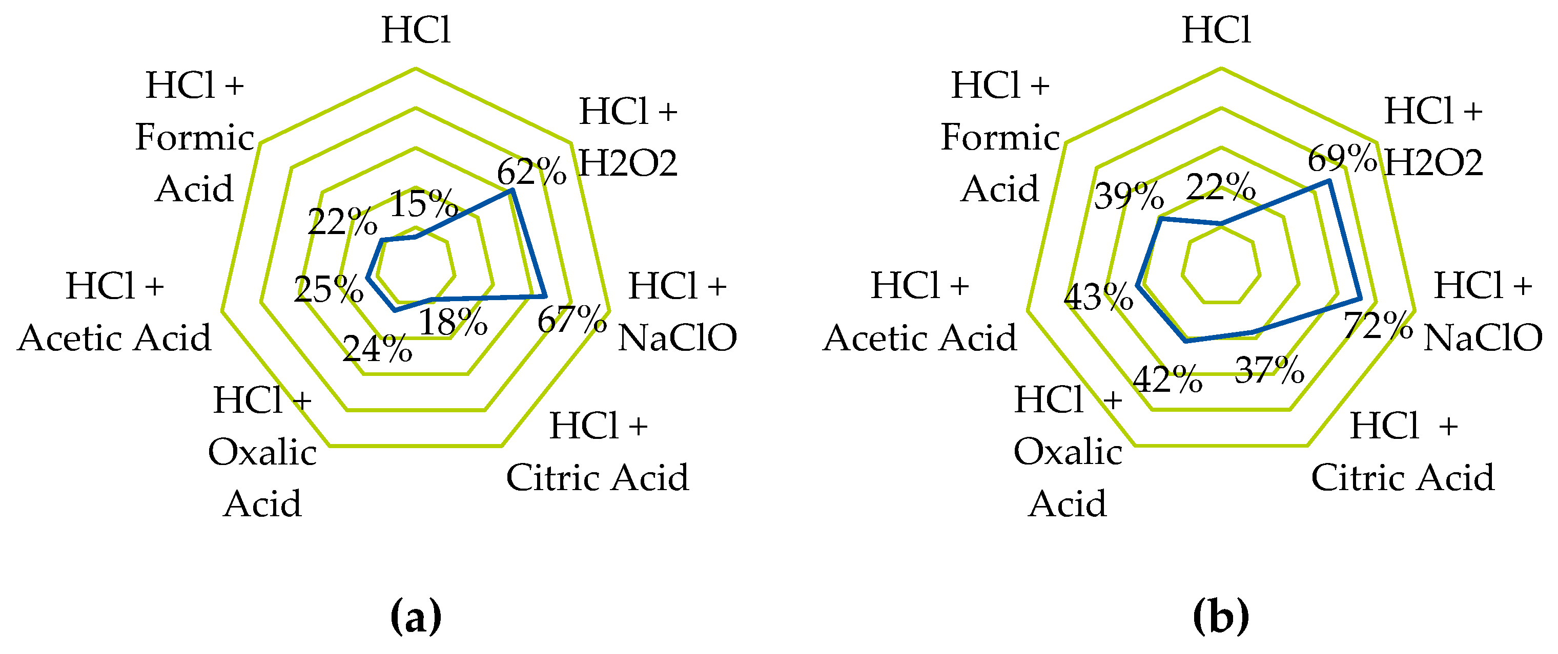
  • The platinum-containing catalyst on the cathode side can be dissolved with high efficiency using standard metallurgical processes. However, these involve highly corrosive chemicals, so a more environmentally friendly alternative was sought and tested on carbon-supported platinum. Using hydrochloric acid in combination with organic acids and other oxidizing agents and salts, leaching efficiencies of >70% could be achieved even before optimization.
These individual highlights, some of which have been tested on model materials, still need to be validated on real EoL electrolyzer materials and scaled up from small- and laboratory-scale investigations to pilot- and production-scale projects. In addition, the entire process chain needs to be validated in sequence, which would require a PEMWE stack to be processed through all the steps of the entire chain. These results can then be used to calculate element-specific recoveries, which can also be used for life cycle assessment and techno-economic assessment.

Author Contributions

Conceptualization, D.G., M.S. and U.A.P.; methodology, B.B.-S., D.G., D.V., M.S., S.A. and T.G.; investigation, B.B.-S., D.G., D.V., M.S., S.A. and T.G.; resources, B.F., J.F., M.R. and U.A.P.; writing—original draft preparation, B.B.-S., D.G., D.V., M.S., S.A. and T.G.; writing—review and editing, B.B.-S., B.F., D.G., D.V., M.R., M.S., S.A., T.G., T.L. and U.A.P.; visualization, D.G., D.V., M.S., S.A., T.G. and T.L.; supervision, U.A.P.; project administration, U.A.P.; funding acquisition, B.F., J.F., M.R. and U.A.P. All authors have read and agreed to the published version of the manuscript.

Funding

This research was funded by the German Federal Ministry of Education and Research (BMBF), grant numbers 03HY111A, B, D, E and G.

Data Availability Statement

Data are contained within the article.

Acknowledgments

The authors acknowledge the financial support by the German Federal Ministry of Education and Research (BMBF) within the project “ReNaRe—Recycling—Nachhaltige Ressourcennutzung” under grant numbers 03HY111A, B, D, E and G. The authors would like to thank Marvin Greifenstein for his support in the development of the morphological box.

Conflicts of Interest

Bernhard Bauer-Siebenlist was employed by the company Heraeus Precious Metals GmbH & Co., KG. The remaining authors declare that the research was conducted in the absence of any commercial or financial relationships that could be construed as a potential conflict of interest.

Abbreviations

The following abbreviations are used in this manuscript:
BPPBipolar plate
CCMCatalyst-coated membrane
EoLEnd of Life
GDLGas diffusion layer
LGDLLiquid–gas diffusion layer
LLPSLiquid–liquid phase/particle separation
PEMProton exchange membrane
PEMFCPEM fuel cell
PEMWEPEM water electrolyzer
PGMPlatinum-group metal
PFSAPerfluorosulfonic acid
PTEPorous transport electrodes
PTFEPolytetrafluoroethylene
PTLPorous transport layer
µXRFMicro-X-ray fluorescence spectroscopy

References

  1. IEA. Global Hydrogen Review 2023; IEA: Paris, France, 2023. [Google Scholar]
  2. Hebling, C.; Ragwitz, M.; Fleiter, T.; Groos, U.; Härle, D.; Held, A.; Jahn, M.; Müller, N.; Pfeifer, T.; Plötz, P.; et al. Eine Wasserstoff-Roadmap für Deutschland; Fraunhofer-Institut für System- und Innovationsforschung ISI: Karlsruhe, Germany; Fraunhofer-Institut für Solare Energiesysteme ISE: Freiburg, Germany; unter Beteiligung von Fraunhofer-Institut für Mikrostruktur von Werkstoffen und Systemen IMWS: Halle, Germany; Fraunhofer-Institut für Keramische Technologien und Systeme IKTS: Dresden, Germany, 2019. [Google Scholar]
  3. Minke, C.; Suermann, M.; Bensmann, B.; Hanke-Rauschenbach, R. Is iridium demand a potential bottleneck in the realization of large-scale PEM water electrolysis? Int. J. Hydrogen Energy 2021, 46, 23581–23590. [Google Scholar] [CrossRef]
  4. IEA. Electrolysers. Available online: https://www.iea.org/energy-system/low-emission-fuels/electrolysers (accessed on 23 May 2025).
  5. Carmo, M.; Fritz, D.L.; Mergel, J.; Stolten, D. A comprehensive review on PEM water electrolysis. Int. J. Hydrogen Energy 2013, 38, 4901–4934. [Google Scholar] [CrossRef]
  6. Shiva Kumar, S.; Himabindu, V. Hydrogen production by PEM water electrolysis–A review. Mater. Sci. Energy Technol. 2019, 2, 442–454. [Google Scholar] [CrossRef]
  7. Bernt, M.; Schröter, J.; Möckl, M.; Gasteiger, H.A. Analysis of Gas Permeation Phenomena in a PEM Water Electrolyzer Operated at High Pressure and High Current Density. J. Electrochem. Soc. 2020, 167, 124502. [Google Scholar] [CrossRef]
  8. Moschovi, A.M.; Zagoraiou, E.; Polyzou, E.; Yakoumis, I. Recycling of Critical Raw Materials from Hydrogen Chemical Storage Stacks (PEMWE), Membrane Electrode Assemblies (MEA) and Electrocatalysts. IOP Conf. Ser. Mater. Sci. Eng. 2021, 1024, 012008. [Google Scholar] [CrossRef]
  9. Aricò, A.S.; Siracusano, S.; Briguglio, N.; Baglio, V.; Di Blasi, A.; Antonucci, V. Polymer electrolyte membrane water electrolysis: Status of technologies and potential applications in combination with renewable power sources. J. Appl. Electrochem. 2013, 43, 107–118. [Google Scholar] [CrossRef]
  10. Bareiß, K.; de la Rua, C.; Möckl, M.; Hamacher, T. Life cycle assessment of hydrogen from proton exchange membrane water electrolysis in future energy systems. Appl. Energy 2019, 237, 862–872. [Google Scholar] [CrossRef]
  11. Valente, A.; Martín-Gamboa, M.; Iribarren, D.; Dufour, J. Deliverable 2.2 Existing End-of-Life Technologies Applicable to FCH Products; Elsevier: Amsterdam, The Netherlands, 2016. [Google Scholar]
  12. Mo, J.; Steen, S.; Han, B.; Kang, Z.; Terekhov, A.; Zhang, F.-Y.; Retterer, S.T.; Cullen, D.A. Investigation of titanium felt transport parameters for energy storage and hydrogen/oxygen production. In Proceedings of the 13th International Energy Conversion Engineering Conference, Orlando, FL, USA, 27–29 July 2015. [Google Scholar]
  13. Toray. Torayca® Carbon Paper for Fuel Cells. Available online: https://toray-cfe.com/en/products/carbon-paper/ (accessed on 29 February 2024).
  14. TANAKA Precious Metals. Electrocatalysts for Fuel Cell/Water Electrolysis (PEM Type). Available online: https://tanaka-preciousmetals.com/en/products/detail/pefcs/?nav=func (accessed on 9 September 2024).
  15. Mott. Porous Transport Layers for Electrolysis. Available online: https://mottcorp.com/product/gas-diffusion-transport-layers/porous-transport-layers/#:~:text=For%20customers%20working%20on%20electrolysis,resistance%20to%20bending%20and%20cracking (accessed on 29 February 2024).
  16. GORE. GORE® PEM for Water electrolysis. Available online: https://www.gore.com/system/files/2024-02/GORE-PEM-Water-Electrolysis-Datasheet-EN.pdf (accessed on 29 February 2024).
  17. Freudenberg. Freundenberg Gas Diffusion Layers-Technical Data. Available online: https://www.fuelcellstore.com/spec-sheets/freudenberg-gdl-technical-data.pdf (accessed on 29 February 2024).
  18. fumatech. Membranes for PEM Water Electrolysis (PEMWE)). Available online: https://www.fumatech.com/en/products/membranes-pem-water-electrolysis/ (accessed on 29 February 2024).
  19. DuPontTM. Nafion® PFSA Membranes-Product information. Available online: http://www.hesen.cn/userfiles/bochi/file/117%E3%80%81115%E5%8F%82%E6%95%B0.pdf (accessed on 29 February 2024).
  20. SGL CARBON. SIGRACET® Fuel Cell Components. Available online: https://www.sglcarbon.com/data/pdf/SIGRACET-Whitepaper.pdf (accessed on 29 February 2024).
  21. Holzapfel, P.; Bühler, M.; Van Pham, C.; Hegge, F.; Böhm, T.; McLaughlin, D.; Breitwieser, M.; Thiele, S. Directly coated membrane electrode assemblies for proton exchange membrane water electrolysis. Electrochem. Commun. 2020, 110, 106640. [Google Scholar] [CrossRef]
  22. Valente, A.; Iribarren, D.; Dufour, J. End of life of fuel cells and hydrogen products: From technologies to strategies. Int. J. Hydrogen Energy 2019, 44, 20965–20977. [Google Scholar] [CrossRef]
  23. Steinmüller, H.; Tichler, R.; Reiter, G.; Koppe, M.; Harasek, M.; Haider, M.; Gawlik, W.; Haas, R. Power to Gas–Eine Systemanalyse. Markt- und Technologiescouting und -Analyse (Endbericht 2014); 2014. [Google Scholar]
  24. Chatterjee, S.; Peng, X.; Intikhab, S.; Zeng, G.; Kariuki, N.N.; Myers, D.J.; Danilovic, N.; Snyder, J. Nanoporous Iridium Nanosheets for Polymer Electrolyte Membrane Electrolysis. Adv. Energy Mater. 2021, 11, 2101438. [Google Scholar] [CrossRef]
  25. Taie, Z.; Peng, X.; Kulkarni, D.; Zenyuk, I.V.; Weber, A.Z.; Hagen, C.; Danilovic, N. Pathway to Complete Energy Sector Decarbonization with Available Iridium Resources using Ultralow Loaded Water Electrolyzers. ACS Appl. Mater. Interfaces 2020, 12, 52701–52712. [Google Scholar] [CrossRef]
  26. Mirshekari, G.; Ouimet, R.; Zeng, Z.; Yu, H.; Bliznakov, S.; Bonville, L.; Niedzwiecki, A.; Capuano, C.; Ayers, K.; Maric, R. High-performance and cost-effective membrane electrode assemblies for advanced proton exchange membrane water electrolyzers: Long-term durability assessment. Int. J. Hydrogen Energy 2021, 46, 1526–1539. [Google Scholar] [CrossRef]
  27. Yu, H.; Bonville, L.; Jankovic, J.; Maric, R. Microscopic insights on the degradation of a PEM water electrolyzer with ultra-low catalyst loading. Appl. Catal. B Environ. 2020, 260, 118194. [Google Scholar] [CrossRef]
  28. Rozain, C.; Mayousse, E.; Guillet, N.; Millet, P. Influence of iridium oxide loadings on the performance of PEM water electrolysis cells: Part II–Advanced oxygen electrodes. Appl. Catal. B Environ. 2016, 182, 123–131. [Google Scholar] [CrossRef]
  29. Ayers, K.; Danilovic, N.; Ouimet, R.; Carmo, M.; Pivovar, B.; Bornstein, M. Perspectives on Low-Temperature Electrolysis and Potential for Renewable Hydrogen at Scale. Annu. Rev. Chem. Biomol. Eng. 2019, 10, 219–239. [Google Scholar] [CrossRef] [PubMed]
  30. Su, H.; Linkov, V.; Bladergroen, B.J. Membrane electrode assemblies with low noble metal loadings for hydrogen production from solid polymer electrolyte water electrolysis. Int. J. Hydrogen Energy 2013, 38, 9601–9608. [Google Scholar] [CrossRef]
  31. Pantò, F.; Siracusano, S.; Briguglio, N.; Aricò, A.S. Durability of a recombination catalyst-based membrane-electrode assembly for electrolysis operation at high current density. Appl. Energy 2020, 279, 115809. [Google Scholar] [CrossRef]
  32. Xu, W.; Scott, K. The effects of ionomer content on PEM water electrolyser membrane electrode assembly performance. Int. J. Hydrogen Energy 2010, 35, 12029–12037. [Google Scholar] [CrossRef]
  33. Pham, C.V.; Escalera-López, D.; Mayrhofer, K.; Cherevko, S.; Thiele, S. Essentials of High Performance Water Electrolyzers–From Catalyst Layer Materials to Electrode Engineering. Adv. Energy Mater. 2021, 11, 2101998. [Google Scholar] [CrossRef]
  34. Bernt, M.; Siebel, A.; Gasteiger, H.A. Analysis of Voltage Losses in PEM Water Electrolyzers with Low Platinum Group Metal Loadings. J. Electrochem. Soc. 2018, 165, F305–F314. [Google Scholar] [CrossRef]
  35. Padgett, E.; Bender, G.; Haug, A.; Lewinski, K.; Sun, F.; Yu, H.; Cullen, D.A.; Steinbach, A.J.; Alia, S.M. Catalyst Layer Resistance and Utilization in PEM Electrolysis. J. Electrochem. Soc. 2023, 170, 084512. [Google Scholar] [CrossRef]
  36. Grigoriev, S.A.; Millet, P.; Fateev, V.N. Evaluation of carbon-supported Pt and Pd nanoparticles for the hydrogen evolution reaction in PEM water electrolysers. J. Power Sources 2008, 177, 281–285. [Google Scholar] [CrossRef]
  37. Wang, W.; Wang, Z.; Wang, J.; Zhong, C.-J.; Liu, C.-J. Highly Active and Stable Pt-Pd Alloy Catalysts Synthesized by Room-Temperature Electron Reduction for Oxygen Reduction Reaction. Adv. Sci. 2017, 4, 1600486. [Google Scholar] [CrossRef] [PubMed]
  38. Deutsche Rohstoffagentur (DERA) in der Bundesanstalt für Geowissenschaften und Rohstoffe (BGR). Preismonitor Dezember 2024; DERA: Berlin, Germany, 2024.
  39. Stähler, M.; Stähler, A.; Scheepers, F.; Carmo, M.; Lehnert, W.; Stolten, D. Impact of porous transport layer compression on hydrogen permeation in PEM water electrolysis. Int. J. Hydrogen Energy 2020, 45, 4008–4014. [Google Scholar] [CrossRef]
  40. Briguglio, N.; Pantò, F.; Siracusano, S.; Aricò, A.S. Enhanced performance of a PtCo recombination catalyst for reducing the H2 concentration in the O2 stream of a PEM electrolysis cell in the presence of a thin membrane and a high differential pressure. Electrochim. Acta 2020, 344, 136153. [Google Scholar] [CrossRef]
  41. Wittstock, R.; Pehlken, A.; Wark, M. Challenges in Automotive Fuel Cells Recycling. Recycling 2016, 1, 343–364. [Google Scholar] [CrossRef]
  42. Lettenmeier, P. Entwicklung und Integration Neuartiger Komponenten für Polymerelektrolytmembran- (PEM) Elektrolyseure. Ph.D. Dissertation, Universität Stuttgart, Stuttgart, Germany, 2018. [Google Scholar]
  43. Inamuddin, D.; Mohammad, A.; Asiri, A.M. Organic-Inorganic Composite Polymer Electrolyte Membranes: Preparation, Properties, and Fuel Cell Applications; Springer International Publishing: Cham, Switzerland, 2017. [Google Scholar]
  44. Bruton, T.A.; Blum, A. Proposal for coordinated health research in PFAS-contaminated communities in the United States. Environ. Health 2017, 16, 120. [Google Scholar] [CrossRef]
  45. Klose, C.; Saatkamp, T.; Münchinger, A.; Bohn, L.; Titvinidze, G.; Breitwieser, M.; Kreuer, K.D.; Vierrath, S. All-Hydrocarbon MEA for PEM Water Electrolysis Combining Low Hydrogen Crossover and High Efficiency. Adv. Energy Mater. 2020, 10, 1903995. [Google Scholar] [CrossRef]
  46. Wegner, R.; Fokkens, E.; Holdt, H.; Bukowsky, H.; Trautmann, M.; Nettesheim, S.; Jakubith, S.; Scholz, P.; Mollenhauer, T.; Theuring, S.; et al. reACT–Rückgewinnung und Wiedereinsatz von Edelmetallen aus Brennstoffzellen. In Recycling und Rohstoffe; Thomé-Kozmiensky, K.J., Goldmann, D., Eds.; TK Verlag Karl Thomé-Kozmiensky: Neuruppin, Germany, 2012; Volume 5, pp. 429–441. [Google Scholar]
  47. Haque, N.; Giddey, S.; Saha, S.; Sernia, P. Recyclability of Proton Exchange Membrane Electrolysers for Green Hydrogen Production. In Proceedings of the New Directions in Mineral Processing, Extractive Metallurgy, Recycling and Waste Minimization, San Diego, CA, USA, 19–23 March 2023; pp. 137–150. [Google Scholar]
  48. Bessarabov, D. (Invited) Membranes with Recombination Catalyst for Hydrogen Crossover Reduction: Water Electrolysis. ECS Trans. 2018, 85, 17–25. [Google Scholar] [CrossRef]
  49. Trinke, P.; Haug, P.; Brauns, J.; Bensmann, B.; Hanke-Rauschenbach, R.; Turek, T. Hydrogen Crossover in PEM and Alkaline Water Electrolysis: Mechanisms, Direct Comparison and Mitigation Strategies. J. Electrochem. Soc. 2018, 165, F502–F513. [Google Scholar] [CrossRef]
  50. Ma, L.; Zimmerer, N.; Schäfer, J.; Quarz, P.; Heckmann, T.; Scharfer, P.; Schabel, W.; Fleischer, J. Investigation on a micro-environment concept for MEA production process supported by numerical simulations. In Proceedings of the FC3-2nd Fuel Cell Conference Chemnitz 2022-Saubere Antriebe, Effizient Produziert: Wissenschaftliche Beiträge und Präsentationen der zweiten Brennstoffzellenkonferenz, Chemnitz, Germany, 31 May–1 June 2022; von Unwerth, T., Drossel, W.-G., Eds.; 2022. [Google Scholar]
  51. Kusoglu, A.; Weber, A.Z. New Insights into Perfluorinated Sulfonic-Acid Ionomers. Chem. Rev. 2017, 117, 987–1104. [Google Scholar] [CrossRef] [PubMed]
  52. Wu, X.; Scott, K.; Puthiyapura, V. Polymer electrolyte membrane water electrolyser with Aquivion® short side chain perfluorosulfonic acid ionomer binder in catalyst layers. Int. J. Hydrogen Energy 2012, 37, 13243–13248. [Google Scholar] [CrossRef]
  53. Carmo, M.; Keeley, G.P.; Holtz, D.; Grube, T.; Robinius, M.; Müller, M.; Stolten, D. PEM water electrolysis: Innovative approaches towards catalyst separation, recovery and recycling. Int. J. Hydrogen Energy 2019, 44, 3450–3455. [Google Scholar] [CrossRef]
  54. Alipour Moghaddam, J.; Parnian, M.J.; Rowshanzamir, S. Preparation, characterization, and electrochemical properties investigation of recycled proton exchange membrane for fuel cell applications. Energy 2018, 161, 699–709. [Google Scholar] [CrossRef]
  55. Kutter, M.; Greve, C.; Maier, M.; Schilling, M.; Mauel, A.; Hilgert, A.; Hoffmann, H.; Hagemeier, W.; Rosin, A.; Muggli, M.; et al. Recycling of perfluorosulfonic acid-based membranes and their Re-application in PEM fuel cells. J. Membr. Sci. 2024, 693, 122370. [Google Scholar] [CrossRef]
  56. Höh, M.A. Poröse Transportschichten für die Polymerelektrolytmembran-Wasserelektrolyse. Ph.D. Dissertation, RWTH Aachen University, Jülich, Germany, 2017. [Google Scholar]
  57. Liu, C.; Shviro, M.; Gago, A.S.; Zaccarine, S.F.; Bender, G.; Gazdzicki, P.; Morawietz, T.; Biswas, I.; Rasinski, M.; Everwand, A.; et al. Exploring the Interface of Skin-Layered Titanium Fibers for Electrochemical Water Splitting. Adv. Energy Mater. 2021, 11, 2002926. [Google Scholar] [CrossRef]
  58. Maier, M.; Smith, K.; Dodwell, J.; Hinds, G.; Shearing, P.R.; Brett, D.J.L. Mass transport in PEM water electrolysers: A review. Int. J. Hydrogen Energy 2022, 47, 30–56. [Google Scholar] [CrossRef]
  59. Borgardt, E.; Panchenko, O.; Hackemüller, F.J.; Giffin, J.; Bram, M.; Müller, M.; Lehnert, W.; Stolten, D. Mechanical characterization and durability of sintered porous transport layers for polymer electrolyte membrane electrolysis. J. Power Sources 2018, 374, 84–91. [Google Scholar] [CrossRef]
  60. Borgardt, E. Mechanische Eigenschaften von katalysatorbeschichteten Membranen für die Polymer-Elektrolyt-Membran Elektrolyse. Ph.D. Thesis, RWTH Aachen, Jülich, Germany, 2021. [Google Scholar]
  61. Zhang, K.; Liang, X.; Wang, L.; Sun, K.; Wang, Y.; Xie, Z.; Wu, Q.; Bai, X.; Hamdy, M.S.; Chen, H.; et al. Status and perspectives of key materials for PEM electrolyzer. Nano Res. Energy 2022, 1, e9120032. [Google Scholar] [CrossRef]
  62. Shirvanian, P.; van Berkel, F. Novel components in Proton Exchange Membrane (PEM) Water Electrolyzers (PEMWE): Status, challenges and future needs. A mini review. Electrochem. Commun. 2020, 114, 106704. [Google Scholar] [CrossRef]
  63. Bekaert. Porous Transport Layers for Electrochemical Production of Hydrogen and Green Molecules. Available online: https://www.bekaert.com/en/product-catalog/metal-fibers/engineered-solutions/porous-transport-layers (accessed on 29 February 2024).
  64. Rakousky, C.; Reimer, U.; Wippermann, K.; Carmo, M.; Lueke, W.; Stolten, D. An analysis of degradation phenomena in polymer electrolyte membrane water electrolysis. J. Power Sources 2016, 326, 120–128. [Google Scholar] [CrossRef]
  65. Kurzweil, P.; Dietlmeier, O.K. Elektrochemische Speicher, 1st ed.; Springer: Wiesbaden, Germany, 2015; pp. XIX, 579. [Google Scholar]
  66. Grigoriev, S.A.; Millet, P.; Volobuev, S.A.; Fateev, V.N. Optimization of porous current collectors for PEM water electrolysers. Int. J. Hydrogen Energy 2009, 34, 4968–4973. [Google Scholar] [CrossRef]
  67. Panchenko, O.; Carmo, M.; Rasinski, M.; Arlt, T.; Manke, I.; Müller, M.; Lehnert, W. Non-destructive in-operando investigation of catalyst layer degradation for water electrolyzers using synchrotron radiography. Mater. Today Energy 2020, 16, 100394. [Google Scholar] [CrossRef]
  68. Bach, M.; Gehre, P.; Biermann, H.; Aneziris, C.G. Recycling of carbon fiber composites in carbon-bonded alumina refractories. Ceram. Int. 2020, 46, 12574–12583. [Google Scholar] [CrossRef]
  69. Stähler, A.; Stähler, M.; Scheepers, F.; Lehnert, W.; Carmo, M. Scalable Implementation of Recombination Catalyst Layers to Mitigate Gas Crossover in PEM Water Electrolyzers. J. Electrochem. Soc. 2022, 169, 034522. [Google Scholar] [CrossRef]
  70. cmc Klebetechnik. Adhesive Film for PEM Fuel Cells and PEM Electrolysis Cells. Available online: https://www.cmc.de/en/wasserstofftechnik-brennstoffzellen (accessed on 29 February 2024).
  71. Mayyas, A.T.; Ruth, M.; Pivovar, B.S.; Bender, G.; Wipke, K.B. Manufacturing Cost Analysis for Proton Exchange Membrane Water Electrolyzers; National Renewable Energy Laboratory (NREL): Golden, CO, USA, 2019.
  72. Langemann, M.; Fritz, D.L.; Müller, M.; Stolten, D. Validation and characterization of suitable materials for bipolar plates in PEM water electrolysis. Int. J. Hydrogen Energy 2015, 40, 11385–11391. [Google Scholar] [CrossRef]
  73. Teuku, H.; Alshami, I.; Goh, J.; Masdar, M.S.; Loh, K.S. Review on bipolar plates for low-temperature polymer electrolyte membrane water electrolyzer. Int. J. Energy Res. 2021, 45, 20583–20600. [Google Scholar] [CrossRef]
  74. Kellenberger, A.; Vaszilcsin, N.; Duca, D.; Dan, M.L.; Duteanu, N.; Stiber, S.; Morawietz, T.; Biswas, I.; Ansar, S.A.; Gazdzicki, P.; et al. Towards Replacing Titanium with Copper in the Bipolar Plates for Proton Exchange Membrane Water Electrolysis. Materials 2022, 15, 1628. [Google Scholar] [CrossRef]
  75. Moreno Soriano, R.; Rojas, N.; Nieto, E.; de Guadalupe González-Huerta, R.; Sandoval-Pineda, J.M. Influence of the gasket materials on the clamping pressure distribution in a PEM water electrolyzer: Bolt torques and operation mode in pre-conditioning. Int. J. Hydrogen Energy 2021, 46, 25944–25953. [Google Scholar] [CrossRef]
  76. Höller, S. Water electrolysis stack for generating hydrogen and oxygen from water. U.S. Patent Application 18/558,387, 7 November 2024. [Google Scholar]
  77. Selamet, Ö.F.; Acar, M.C.; Mat, M.D.; Kaplan, Y. Effects of operating parameters on the performance of a high-pressure proton exchange membrane electrolyzer. Int. J. Energy Res. 2013, 37, 457–467. [Google Scholar] [CrossRef]
  78. Borgardt, E.; Giesenberg, L.; Reska, M.; Müller, M.; Wippermann, K.; Langemann, M.; Lehnert, W.; Stolten, D. Impact of clamping pressure and stress relaxation on the performance of different polymer electrolyte membrane water electrolysis cell designs. Int. J. Hydrogen Energy 2019, 44, 23556–23567. [Google Scholar] [CrossRef]
  79. Hydrogen Europe. Hydrogen Europe Position Paper on PFAS; HYDROGEN EUROPE: Brussels, Belgium, 2023. [Google Scholar]
  80. Selamet, O.F.; Ergoktas, M.S. Effects of bolt torque and contact resistance on the performance of the polymer electrolyte membrane electrolyzers. J. Power Sources 2015, 281, 103–113. [Google Scholar] [CrossRef]
  81. Smolinka, T.; Lehner, F.; Kiemel, S. Studie IndWEDe-Industrialisierung der Wasserelektrolyse in Deutschland: Chancen und Herausforderungen für Nachhaltigen Wasserstoff für Verkehr, Strom und Wärme; Nationale Organisation Wasserstoff- und Brennstoffzellentechnologie–NOW GmbH: Berlin, Germany, 2018. [Google Scholar]
  82. Caparrós Mancera, J.J.; Segura Manzano, F.; Andújar, J.M.; Vivas, F.J.; Calderón, A.J. An Optimized Balance of Plant for a Medium-Size PEM Electrolyzer: Design, Control and Physical Implementation. Electronics 2020, 9, 871. [Google Scholar] [CrossRef]
  83. Selamet, Ö.F.; Becerikli, F.; Mat, M.D.; Kaplan, Y. Development and testing of a highly efficient proton exchange membrane (PEM) electrolyzer stack. Int. J. Hydrogen Energy 2011, 36, 11480–11487. [Google Scholar] [CrossRef]
  84. Siracusano, S.; Baglio, V.; Di Blasi, A.; Briguglio, N.; Stassi, A.; Ornelas, R.; Trifoni, E.; Antonucci, V.; Aricò, A.S. Electrochemical characterization of single cell and short stack PEM electrolyzers based on a nanosized IrO2 anode electrocatalyst. Int. J. Hydrogen Energy 2010, 35, 5558–5568. [Google Scholar] [CrossRef]
  85. SIEMENS. SILYZER 300-The Next Paradigm of PEM Electrolysis; SIEMENS: Munich, Germany, 2018. [Google Scholar]
  86. Bosch GmbH. Hybrion PEM Electrolysis Stack Brochure. Available online: https://www.bosch-hydrogen-energy.com/pem-electrolysis/pem-elektrolysis-stacks/ (accessed on 13 June 2025).
  87. Directive 2008/98/EC of the European Parliament and of the Council of 19 November 2008 on Waste and Repealing Certain Directives. 2008. Available online: https://eur-lex.europa.eu/eli/dir/2008/98/oj/eng (accessed on 31 May 2024).
  88. Al Assadi, A.; Goes, D.; Baazouzi, S.; Staudacher, M.; Malczyk, P.; Kraus, W.; Nägele, F.; Huber, M.F.; Fleischer, J.; Peuker, U.; et al. Challenges and prospects of automated disassembly of fuel cells for a circular economy. Resour. Conserv. Recycl. Adv. 2023, 19, 200172. [Google Scholar] [CrossRef]
  89. Martens, H.; Goldmann, D. Recyclingtechnik; Springer: Wiesbaden, Germany, 2016; pp. XXIII, 556. [Google Scholar]
  90. Kumar, A.; Holuszko, M.; Espinosa, D.C.R. E-waste: An overview on generation, collection, legislation and recycling practices. Resour. Conserv. Recycl. 2017, 122, 32–42. [Google Scholar] [CrossRef]
  91. Werner, D.; Peuker, U.A.; Mütze, T. Recycling Chain for Spent Lithium-Ion Batteries. Metals 2020, 10, 316. [Google Scholar] [CrossRef]
  92. Melke, J.; Maletzko, A.; Gomez Villa, E.D.; Bornet, A.; Wiberg, G.K.H.; Arenz, M.; Sandig-Predzymirska, L.; Thiere, A.; Charitos, A.; Stelter, M.; et al. Recycalyse–New Sustainable and Recyclable Catalytic Materials for Proton Exchange Membrane Electrolysers. Chem. Ing. Tech. 2024, 96, 126–142. [Google Scholar] [CrossRef]
  93. Hanisch, C.; Loellhoeffel, T.; Diekmann, J.; Markley, K.J.; Haselrieder, W.; Kwade, A. Recycling of lithium-ion batteries: A novel method to separate coating and foil of electrodes. J. Clean. Prod. 2015, 108, 301–311. [Google Scholar] [CrossRef]
  94. Werner, D.M.; Mütze, T.; Peuker, U.A. Influence of Pretreatment Strategy on the Crushing of Spent Lithium-Ion Batteries. Metals 2022, 12, 1839. [Google Scholar] [CrossRef]
  95. Vanegas, P.; Peeters, J.R.; Cattrysse, D.; Tecchio, P.; Ardente, F.; Mathieux, F.; Dewulf, W.; Duflou, J.R. Ease of disassembly of products to support circular economy strategies. Resour. Conserv. Recycl. 2018, 135, 323–334. [Google Scholar] [CrossRef]
  96. Khatib, F.N.; Wilberforce, T.; Ijaodola, O.; Ogungbemi, E.; El-Hassan, Z.; Durrant, A.; Thompson, J.; Olabi, A.G. Material degradation of components in polymer electrolyte membrane (PEM) electrolytic cell and mitigation mechanisms: A review. Renew. Sustain. Energy Rev. 2019, 111, 1–14. [Google Scholar] [CrossRef]
  97. Millet, P.; Ranjbari, A.; de Guglielmo, F.; Grigoriev, S.A.; Auprêtre, F. Cell failure mechanisms in PEM water electrolyzers. Int. J. Hydrogen Energy 2012, 37, 17478–17487. [Google Scholar] [CrossRef]
  98. Feng, Q.; Yuan, X.Z.; Liu, G.; Wei, B.; Zhang, Z.; Li, H.; Wang, H. A review of proton exchange membrane water electrolysis on degradation mechanisms and mitigation strategies. J. Power Sources 2017, 366, 33–55. [Google Scholar] [CrossRef]
  99. European Environment Agency. Accelerating the Circular Economy in Europe-State and Outlook 2024. 2024. Available online: https://www.eea.europa.eu/en/analysis/publications/accelerating-the-circular-economy (accessed on 31 May 2024).
  100. DIN/TS 54405:2020-12; Construction Adhesives-Guideline for Separation and Recycling of Adhesives and Substrates from Bonded Joints. DIN Media: Berlin, Germany, 2020.
  101. Bharti, A.; Natarajan, R. Recovery of expensive Pt/C catalysts from the end-of-life membrane electrode assembly of proton exchange membrane fuel cells. RSC Adv. 2020, 10, 35057–35061. [Google Scholar] [CrossRef]
  102. Arlt, C.-R.; Brekel, D.; Franzreb, M. Continuous fractionation of nanoparticles based on their magnetic properties applying simulated moving bed chromatography. Sep. Purif. Technol. 2021, 259, 118123. [Google Scholar] [CrossRef]
  103. Rhein, F.; Scholl, F.; Nirschl, H. Magnetic seeded filtration for the separation of fine polymer particles from dilute suspensions: Microplastics. Chem. Eng. Sci. 2019, 207, 1278–1287. [Google Scholar] [CrossRef]
  104. Giesler, J.; Pesch, G.R.; Weirauch, L.; Schmidt, M.-P.; Thöming, J.; Baune, M. Polarizability-Dependent Sorting of Microparticles Using Continuous-Flow Dielectrophoretic Chromatography with a Frequency Modulation Method. Micromachines 2020, 11, 38. [Google Scholar] [CrossRef]
  105. Ahn, S.; Rudolph, M. Development of Fine Particle Mechanical Separation Processes with Representative Catalyst Materials for Recycling PEM Water Electrolyzers Exploiting their Wetting Characteristics. ChemCatChem 2023, 16, e202300931. [Google Scholar] [CrossRef]
  106. Miettinen, T.; Ralston, J.; Fornasiero, D. The limits of fine particle flotation. Miner. Eng. 2010, 23, 420–437. [Google Scholar] [CrossRef]
  107. Ahn, S.; Patil, S.; Rudolph, M. Ultrafine Particle Recycling—Efficiency of the Hydrophobic Double Emulsion Technique for the Selective Agglomeration and Froth Flotation of Ultrafine Cathode Catalyst Particles from PEM Water Electrolyzers. ACS Eng. Au 2024, 5, 57–65. [Google Scholar] [CrossRef]
  108. Machunsky, S.; Peuker, U.A. Liquid-Liquid Interfacial Transport of Nanoparticles. Phys. Sep. Sci. Eng. 2007, 2007, 034832. [Google Scholar] [CrossRef]
  109. Heilmann, C.; Ditscherlein, L.; Peuker, U.A. Influence of Hydrolyzed Metal Ions and Surfactants on the Phase Transfer of Al2O3, SiO2, and SnO2. Langmuir 2024, 40, 2543–2550. [Google Scholar] [CrossRef]
  110. Olbrich, W.; Kadyk, T.; Sauter, U.; Eikerling, M. Review—Wetting Phenomena in Catalyst Layers of PEM Fuel Cells: Novel Approaches for Modeling and Materials Research. J. Electrochem. Soc. 2022, 169, 054521. [Google Scholar] [CrossRef]
  111. Ahn, S.; Rudolph, M. Impact of ionomer containing particles on the selective mechanical separation processes of PEM water electrolyzer recycling for PGM recovery. In Proceedings of the International Mineral Processing Congress, Washington, DC, USA, 29 September–3 October 2024. [Google Scholar]
  112. Madhav, D.; Wang, J.; Keloth, R.; Mus, J.; Buysschaert, F.; Vandeginste, V. A Review of Proton Exchange Membrane Degradation Pathways, Mechanisms, and Mitigation Strategies in a Fuel Cell. Energies 2024, 17, 998. [Google Scholar] [CrossRef]
  113. Granados-Fernández, R.; Montiel, M.A.; Díaz-Abad, S.; Rodrigo, M.A.; Lobato, J. Platinum Recovery Techniques for a Circular Economy. Catalysts 2021, 11, 937. [Google Scholar] [CrossRef]
  114. Sverdrup, H.U.; Ragnarsdottir, K.V. A system dynamics model for platinum group metal supply, market price, depletion of extractable amounts, ore grade, recycling and stocks-in-use. Resour. Conserv. Recycl. 2016, 114, 130–152. [Google Scholar] [CrossRef]
  115. Saguru, C.; Ndlovu, S.; Moropeng, D. A review of recent studies into hydrometallurgical methods for recovering PGMs from used catalytic converters. Hydrometallurgy 2018, 182, 44–56. [Google Scholar] [CrossRef]
  116. Asamoah-Bekoe, Y. Investigation of the Leaching of the Platinum Group Metal Concentrate in Hydrochloric Acid Solution by Chlorine. Ph.D. Thesis, University of the Witwatersrand, Johannesburg, South Africa, 1998. [Google Scholar]
  117. Wilkens, M.; Peuker, U.A. Grundlagen und aktuelle Entwicklungen der Filterkuchenwaschung. Chem. Ing. Tech. 2012, 84, 1873–1884. [Google Scholar] [CrossRef]
  118. Sauer, F.; Löwer, E.; Henn, H.; Peuker, U.; Hoffner, B. Displacement Washing of Filter Cakes With a Fine Particle Top Layer. Chem. Eng. Technol. 2025, 48, e202400394. [Google Scholar] [CrossRef]
Figure 1. Model stack of PEMWE at component level.
Recycling 10 00121 g001
Figure 2. Conceptual outline of combined mechanical and hydrometallurgical recycling chain for PEMWEs; colored process steps were investigated experimentally (proof of principle trials).
Recycling 10 00121 g002
Figure 3. The equipment for disassembling a stack into its individual components using a cutting tool.
Recycling 10 00121 g003
Figure 4. (a) µXRF mapping of sample indicating sulfur and platinum on cathode side of type A milled at 10.2 m/s with calculated decoating efficiency of 88.0%; (b) decoating efficiencies of three types of CCM in laboratory hammer mill as functions of circumferential speed (circular discharge screen size 1 mm).
Recycling 10 00121 g004
Figure 5. Water contact angle of anode and cathode side of different CCM types determined with static sessile drop method.
Recycling 10 00121 g005
Figure 6. Scheme of LLPS for ultrafine particle separation. Hydrophobic particles stabilized in organic phase, and recovery of hydrophilic particles can be accomplished in aqueous phase.
Recycling 10 00121 g006
Figure 7. Leaching efficiency of platinum after 6 h with aqua regia and with hydrochloric acid with and without oxidants (H2O2, NaClO) at 25 °C and 60 °C.
Recycling 10 00121 g007
Figure 8. Leaching efficiency, i.e., platinum recovery, after 6 h with hydrochloric acid with organic acids at 25 °C (a) and 60 °C (b).
Recycling 10 00121 g008
Table 1. Morphological box of PEMWE stack components and their different characteristic variants derived from literature.
ComponentsDifferent. PropertiesPEMWE Manifestations
Membrane and Catalyst Layermembrane materialperfluorosulfonic acid (PFSA)hydrocarbon
membrane thickness51 µm127 µm254 µm
anode materialIrO2Ir blackIrRuO2Ir mixed metal
anode loading0.3 mgIr cm−21 mgIr cm−23 mgIr cm−2
anode layer thickness2 µm 12 µm
cathode materialPt blackPt carbon-supportedPd
cathode loading0.1 mgPt cm−20.5 mgPt cm−21 mgPt cm−2
cathode layer thickness8 µm21 µm
Porous Transport LayerLGDL materialTi
LGDL thickness100 µm250 µm2.000 µm3.175 µm
LGDL specificationmeshfeltfoamgridsintered Ti powder
LGDL porosity30%50%
LGDL coating materialAuPtIrnone
GDL materialcarbon
GDL thickness110 µm370 µm
GDL specificationfeltpapernonwovens
GDL porosity75%80%
Membrane Electrode Assembly Configurationsframe/subgasket structureyesno
one-sided around CCMtwo-sided around CCM
GDL enclosedGDL overlaid
frame/subgasket materialPIPENPEEKPPSPTFE
Bipolar Platesbipolar plate materialTistainless steelgraphiteAl
bipolar plate coatingyesno
bipolar plate coating materialPtAuTiIrNb
bipolar plate thickness300 µm3.000 µm
flow fieldintegrated flow fieldflow field as separate component
Sealing ElementsmaterialPTFEsiliconeTeflonFKMEPDMPVDPFArubber
thickness250 µm1.640 µm
production/joining methodinjection moldingscreen-printingdispensing
sealing conceptsealing on MEAsealing on bipolar plate
Clamping Systemend plate materialAlstainless steel
fixation/compression elementstie rodtension bands
position of compression elementsinsideoutside
Stack Layout and Active Areastack formatrectangular/quadraticcircular
size stack area0.0025 m20.7 m21 m2
Table 2. Precious metal yields of dissolved membrane after separation of ionomer dispersion.
CCMPlatinum Recovery
in Residue (wt-%)
Iridium Recovery
in Residue (wt-%)
Type #1—Spent PEMWE>99%>99%
Type #2—Spent PEMFC>99%Not contained
Disclaimer/Publisher’s Note: The statements, opinions and data contained in all publications are solely those of the individual author(s) and contributor(s) and not of MDPI and/or the editor(s). MDPI and/or the editor(s) disclaim responsibility for any injury to people or property resulting from any ideas, methods, instructions or products referred to in the content.

