Article

Optimization of the Recycling Process for Aligned Short Carbon Fiber TuFF Composites

1
Center for Composite Materials, University of Delaware, 101 Academy St, Newark, DE 19716, USA
2
Department of Mechanical Engineering, Abdullah Gul University, Kayseri 38080, Turkey
3
Composites Automation LLC, University of Delaware, 7 McMillan Way, Newark, DE 19713, USA
*
Author to whom correspondence should be addressed.
Recycling 2025, 10(2), 55; https://doi.org/10.3390/recycling10020055
Submission received: 17 February 2025 / Revised: 24 March 2025 / Accepted: 26 March 2025 / Published: 1 April 2025
(This article belongs to the Special Issue Challenges and Opportunities in Plastic Waste Management)

Abstract

:
Recycling of carbon fibers enables a sustainable feedstock for industrial applications of high-performance composite materials. This allows light weighting with recycled carbon fibers due to their superior mechanical properties while reducing the high embodied energy and cost of virgin carbon fiber composites. This study optimizes a pyrolysis cycle for fiber recovery of an aerospace-grade thermoset prepreg and a cleaning (oxidation) step to minimize fiber degradation and left-over resin residue, enabling dispersion and alignment of the recycled, discontinuous fibers in the Tailorable Universal Feedstock for Forming alignment process. The study balances the influence of the optimized thermal cycle (pyrolysis + oxidation step) on recycled carbon fiber strength retention with the ability to disperse at the filament level to create aligned, recycled carbon fiber composite samples with high fiber volume fraction. The optimized thermal cycle for efficient fiber recovery applied a pyrolysis step at 500 °C for 4 h in an inert gas environment and an additional oxidation step at the same temperature for 100 min. This resulted in ~20% strength degradation of the fiber compared to the virgin fiber. The processed recycled composite achieved 44% fiber volume fraction with full modulus translation (~128 GPa) compared to the virgin continuous composite with strength translation (~870 MPa), reaching ~50%.

1. Introduction

The carbon fiber (CF) industry has seen substantial growth over the past decade. Carbon fiber composites (CFC) have increasingly replaced traditional metallic materials due to their low density, high strength and rigidity, and resistance to corrosion in various high-performance applications. In 2000, the global market for CFC was less than 20,000 tons annually, and it has since grown threefold, with forecasts predicting it will reach 140,000 tons in the 2020s. This growth, along with environmental regulations and concerns, highlights the importance of CF recycling and reuse. Reducing CF waste with its high embodied energy through recycling is energy-efficient and mandated by legislation in many countries. The push for “green” applications as part of industry social responsibility is a key factor driving the inclusion of recycling strategies in composite end-use applications [1,2,3,4,5,6,7,8,9,10].
The recycling of CFC is still in its early stages in the US, with promising technologies like solvolysis, pyrolysis, and thermolysis being developed through collaborations between small businesses and large OEMs in both the US and Europe. Materials Innovation Technologies (MIT, Fletcher, NC, USA), now Carbon Conversions Inc., mechanically shreds carbon fiber reinforced plastic (CFRP) into smaller pellets, pyrolyzes them and converts the short fibers into preforms or rolled goods. Adherent Technologies, Inc. (Albuquerque, NM, USA) uses a mechanical process to reduce the material to coupon size, followed by wet chemical degradation of the polymer to separate the fibers. Adherent licenses and sells complete plant installations for their process. In Europe, recycling vendors such as GEN 2 Carbon and CFK Valley Stade Recycling GmbH employ similar technical approaches to recycle CFRP waste [11,12,13,14,15,16].
All these competing technologies produce recycled carbon fiber (rCF) in discontinuous chopped or short fiber random and semi-aligned forms, as shown in Figure 1, which leads to reduced mechanical properties in composite parts. The utilization of randomly oriented fibers significantly lower production costs; however, this resulting microstructure adversely affects the desired fiber volume fraction (FVF) and mechanical properties of the composite material. For instance, the tensile strength of MIT’s DEP recycled preforms (156 MPa with a fiber length distribution between 6 and 25 mm) molded with polyester is approximately 20% of that of an equivalent continuous CF quasi-isotropic prepreg composite at 50% FVF, while the resultant tensile modulus translation is 50% (22 GPa). This is primarily due to the random fiber orientation and low fiber loading of the recycled preform [17,18,19,20].
Longana et al. [21,22] evaluated their fiber alignment process with rCFs from previously fabricated aligned short fiber coupons. Their HiPerDiF process [10,19,20,21,22,23,24] aligns millimeter-long fibers dispersed in water between a series of parallel plates. This process has the potential to achieve a higher FVF, with 55% reported in their study, through improved packing efficiency of the parallel fiber network. They fabricated recycled composite specimens with FVFs between 20.1% and 28.5%. The lower values were attributed to a reduction in fiber alignment caused by fiber shortening during the recycling process. They reported a composite tensile strength of 460 MPa and stiffness of 52 GPa. Turner et al., in their study on the challenges of rCF composite technology, concluded that fiber alignment is a critical factor in producing competitive rCFs [25].
In our previous research, Ozdemir et al. [26] utilized the TuFF process to reprocess rCFs recovered via solvolysis from uncured prepreg into high-performance composites. The solvolysis process did not degrade fiber mechanical properties, and challenges with dispersion with the rCFs were addressed. A key lesson learned from this work is that the recycled fibers must be free of residue for the TuFF alignment process to be effective. With the addition of an elevated temperature pyrolysis step to remove residue from the solvolysis process, the successful use of recycled short fibers in reprocessing highly aligned short fiber composites (SFCs) using the TuFF process has been demonstrated with the achievement of full stiffness and ~60% strength translation. Nevertheless, this approach has been limited to uncured prepreg, restricting its recycling applications.
Pyrolysis is an alternative route to recover the fiber content from CFCs. It offers notable advantages over solvolysis, including the elimination of solvent disposal with associated environmental footprint and the ability to recover CFs from cured end-of-life CFC products. In our current study, a methodology is developed to optimize the thermal cycle to recover fiber content from an aerospace-grade thermoset prepreg, minimizing fiber degradation and left-over residue to enable filament level dispersion needed for subsequent alignment processing in the TuFF approach. The methodology can be applied to any composite waste material made with different resins, including cured CFCs. The resulting rTuFF parts target higher FVF (~50%) to be used in high-performance applications.

2. Results and Discussion

2.1. Non-Isothermal TGA

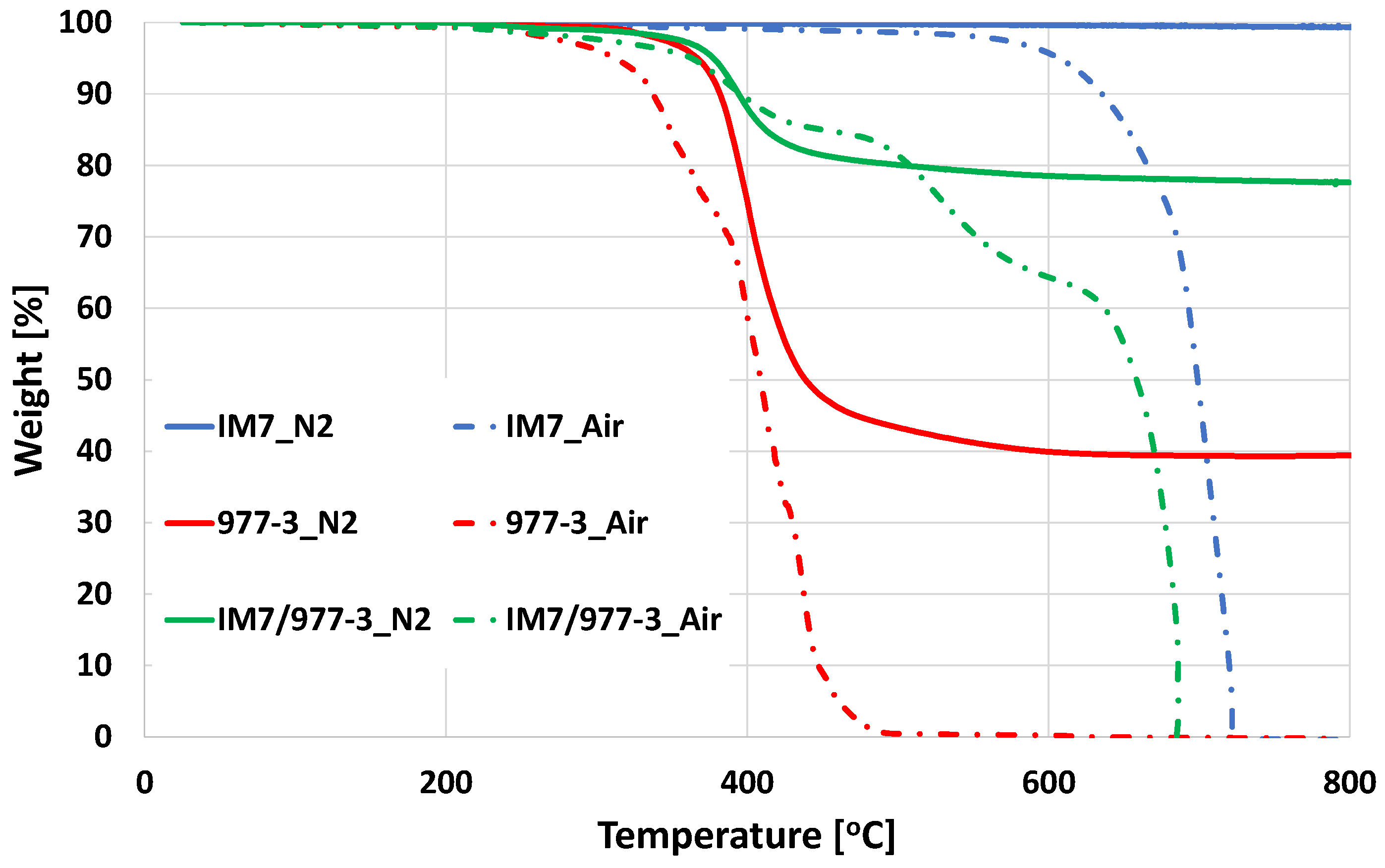
The onset temperature of material degradation was evaluated, as shown in Figure 2. Under N2, the CF exhibited no degradation across the temperature range, while the resin material experienced approximately 70% weight loss at 450 °C, with no further weight loss observed at higher temperatures. The resin formed a char, with the residue amounts unchanged in the absence of an oxidizing environment. However, in an oxygen-rich environment, such as air, both materials experienced significantly higher weight loss. IM7 degradation remained below 5% until 600 °C, with the peak loss rate occurring around 700 °C. The degradation of the neat resin began at 300 °C, with full weight loss occurring at 500 °C in air.
An optimal dwell temperature range must effectively degrade the resin content while minimizing the impact on fiber properties. Based on the behavior of both materials from the non-isothermal runs, an oxidation step is necessary for complete resin removal with a temperature range of 450 °C to 550 °C as the starting point for isothermal experiments. The process begins with initial heating under N2 to degrade a substantial portion of the polymer, followed by switching to an air environment to reduce the required exposure time during the oxidation step [27,28].

2.2. Isothermal TGA

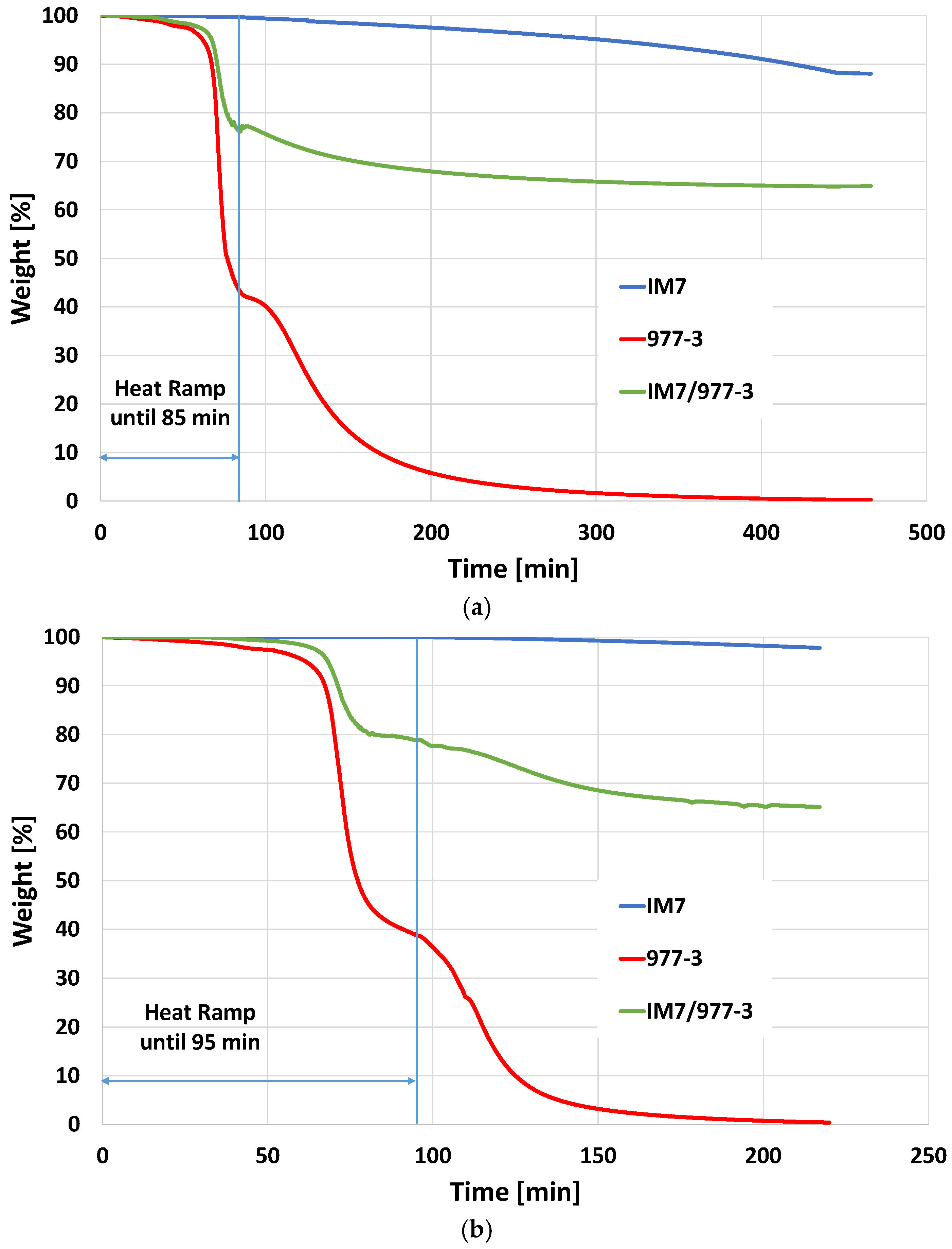
Figure 3a presents the TGA data of a thermal cycle with a dwell temperature of 450 °C, showing the weight loss of IM7 fiber, neat resin, and prepreg material. The heat ramp takes 85 min, degrading ~20% of the prepreg, equivalent to ~60% of the resin content (given the weight ratio of roughly 2:1 fiber to resin in the prepreg). A 33.5% prepreg weight loss is achieved 81 min into the dwell cycle. However, to fully remove the resin residues, an oxidation step is required. Due to the lower temperature needed for residue removal, a longer dwell time in the air was necessary. This prolonged exposure to oxygen led to fiber degradation, with a weight loss rate of approximately −0.018% per minute.
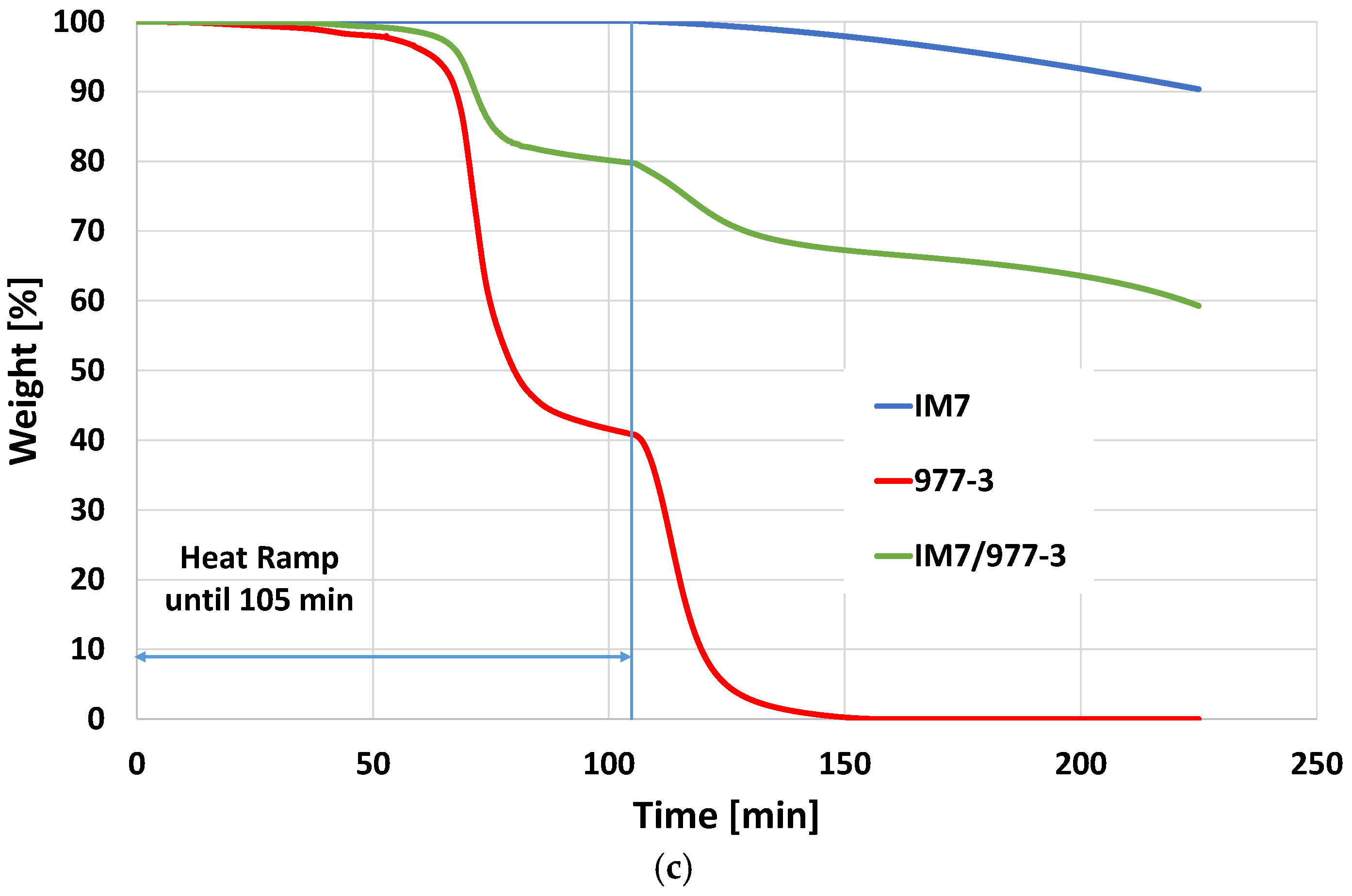
For dwell temperatures of 500 °C (Figure 3b) and 550 °C (Figure 3c), a similar resin removal percentage of approximately 60% was observed during the pyrolysis step, indicating that residual resin removal is insensitive to higher temperatures in an inert environment. It was also noted that the prepreg begins to degrade under N2 after approximately 80 min or around 400 °C, with weight loss of around 20% before the start of each dwell cycle (and then switch to the air environment). The prepreg degradation behavior observed confirms the non-isothermal data of the neat resin sample. Variation in prepreg weight loss between different runs is mainly due to variation in resin content in the small TGA samples.
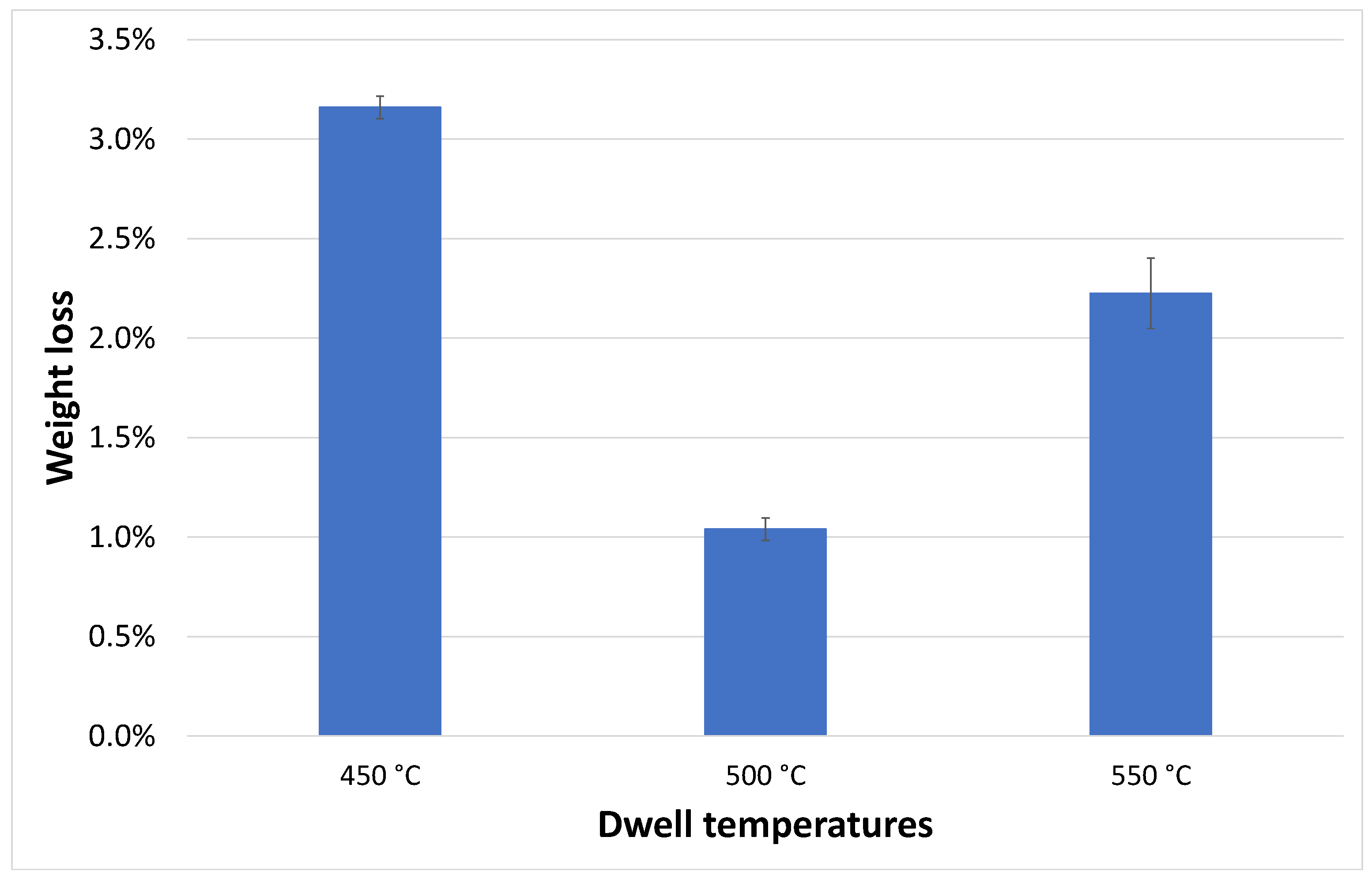
However, to achieve 33% prepreg (including residues) loss under air during the dwell phase, dwell time decreases as temperature increases due to faster degradation rates at higher temperatures. Table 1 presents the loss and loss rate as well as the required dwell time for three levels of resin residue, and Figure 4 compares the weight loss of IM7 fiber at those dwell temperatures and time combinations. The fiber loss is minimal at 500 °C (~1.04%), compared to higher losses at 450 °C (~3.16%) and 550 °C (~2.23%) after the oxidation step. The results are confirmed with a second test with the same parameters, and the values provided are the average values of the two runs. At the lower dwell temperature of 450 °C, the exposure time (257 min) is significantly longer, allowing for prolonged fiber degradation. At 550 °C, the degradation rate accelerates, resulting in greater fiber weight loss than at 500 °C even at a lower dwell time of 35 min. Therefore, the thermal cycle is scaled at 500 °C, as this temperature provides an optimal balance between efficient resin removal and maximizing the potential for fiber strength retention in the recovered fibers.

2.3. Batch Pyrolysis

A series of GLO Oven experiments at increasing dwell temperatures for the oxidation step was conducted to evaluate dispersion and fiber strength retention. The details of each run with specific IDs are presented in Table 2.

2.3.1. Lab Scale Dispersion and SEM Analysis

The dispersion assessment involves transferring the short fibers recovered in the GLO furnace into a small jar (150 mm tall) containing water. Upon adding the fibers to the solution, agitation is applied to separate the fibers. The water-to-fiber ratio is scaled as per the dilution ratio of the TuFF process, resulting in water level variation for each picture. However, it is critical to consider that, in all cases, the concentration of fiber is consistent. This is a qualitative assessment of the dispersion at a lab scale to provide a visual confirmation to proceed. In cases where the thermal cycle was ineffective, and residue remains, the fibers do not separate, and agglomerates settle rapidly, as seen in Figure 5a, where there is no oxidation step at all and Figure 5b, where the oxidation is only for 60 min. Conversely, the successful oxidation step removes residues, resulting in mostly dispersed fibers at the filament level, which float along with the solution that can be seen in Figure 5c–f for an oxidation time of 70 min and longer.
SEM images of different oxidation durations of samples extracted from the dispersion tests are presented below in Figure 6. The SEM images obtained after 0–70 min of oxidation time exhibited a parallel fiber network with residue left over. The 80 min SEM sample showed a random orientation with only a small number of parallel fibers. The parallel fiber network indicates poor dispersion as the separation of the parallel network of the prepreg was not broken up. Longer oxidation times resulted in a random network identifying full dispersion for those dwell times. It must be noted that the sample size for the SEM is very small and provides a no-go for oxidation times where a parallel network is observed, with longer oxidation times required when larger amounts of recycled fibers are being processed.

2.3.2. Single Fiber Tension Test

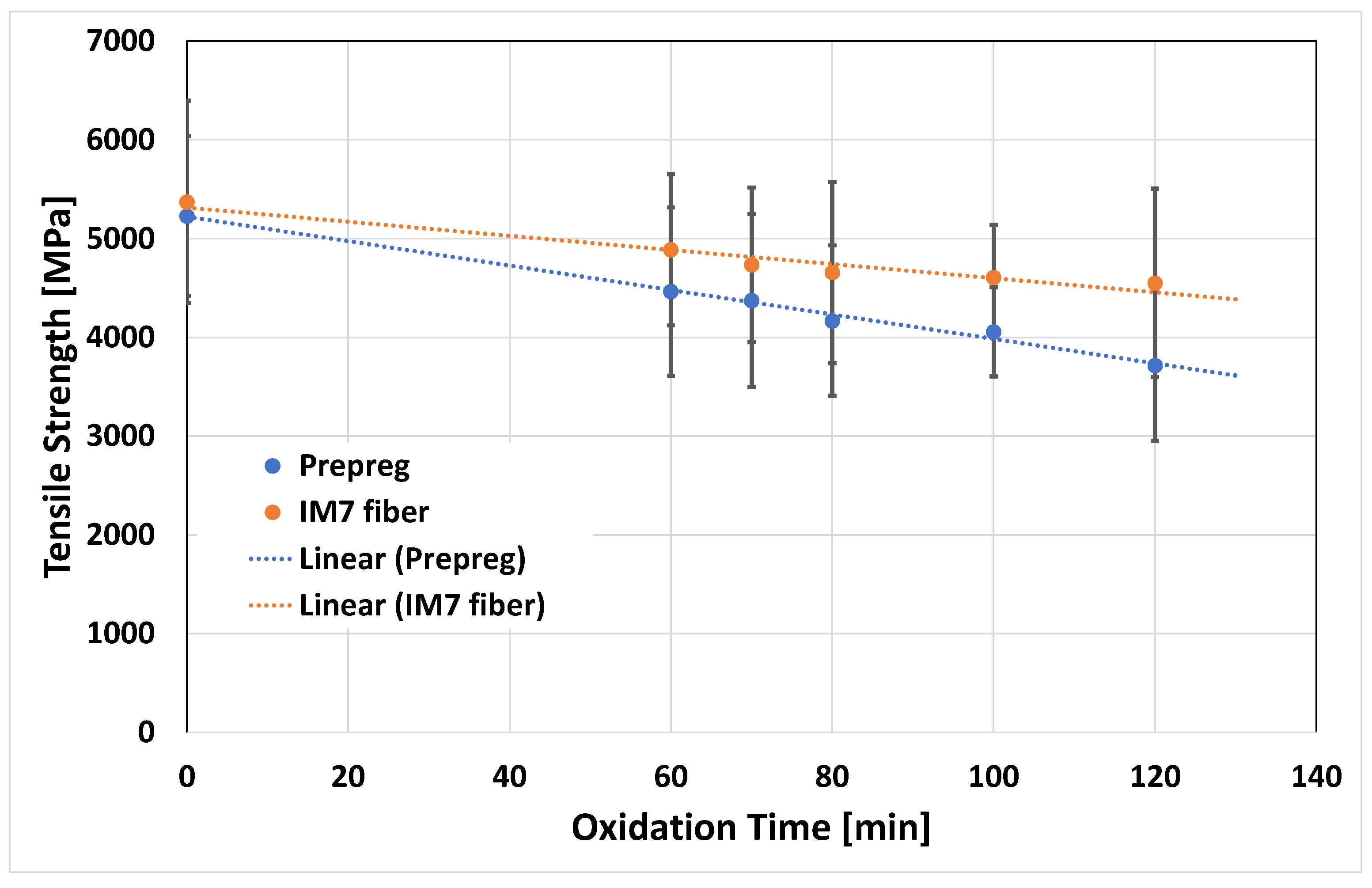
Samples of ~76 mm long prepreg and virgin fiber were also subjected to the optimized thermal cycle, as mentioned earlier. The long fibers recovered from the prepreg and the virgin fiber material after recycling underwent testing to assess fiber strength, which was then compared to the strength properties of virgin fiber. The results are summarized in Table 3, and the degradation trend is depicted in Figure 7. The strength of the virgin fiber (5400 MPa ± 1000 MPa) fell within one standard deviation of the Hexcel datasheet values for IM7 fiber at 5516 MPa. While the fibers did not degrade after the pyrolysis step, exposure to air during the oxidation step significantly reduced their strength. At an oxidation time of 120 min, the fiber strength of the recovered virgin and prepreg fiber material decreased to 4550 MPa ± 954 MPa and 3715 MPa ± 762 MPa, respectively. This represents an 18% and 33% reduction in fiber strength compared to the virgin material. Both materials exhibit a decreasing trend in tensile strength with increasing oxidation time. However, the slope of the degradation trend suggests that fibers in prepreg degrade at a faster rate compared to virgin IM7 fibers. This is evident from the steeper downward slope of the linear trend line for prepreg fibers. Notably, the virgin material exhibited higher strength numbers compared to the fiber material recovered from the prepreg. This discrepancy can be understood by considering carbon fibers as chains, where high temperatures induce chain breakage, resulting in a drastic reduction in strength. In virgin fibers, these are clean chains unaffected by external sources such as surface effects or resin residues. Conversely, in recycled fibers, the resin residue on the fiber surface may act as a weak link in the chain, inducing stresses at specific locations on the fiber surface. At increasing loads, this weak link breaks first, facilitating the propagation of breaks throughout the chain more easily compared to virgin fiber due to localized stress concentrations. Essentially, the resin residue accelerates chain breakage. Similar studies on the impact of surface defects on fiber degradation have been explored [1,11,29,30]. Additional studies are needed to explain the mechanisms in detail and will be the focus of additional studies.
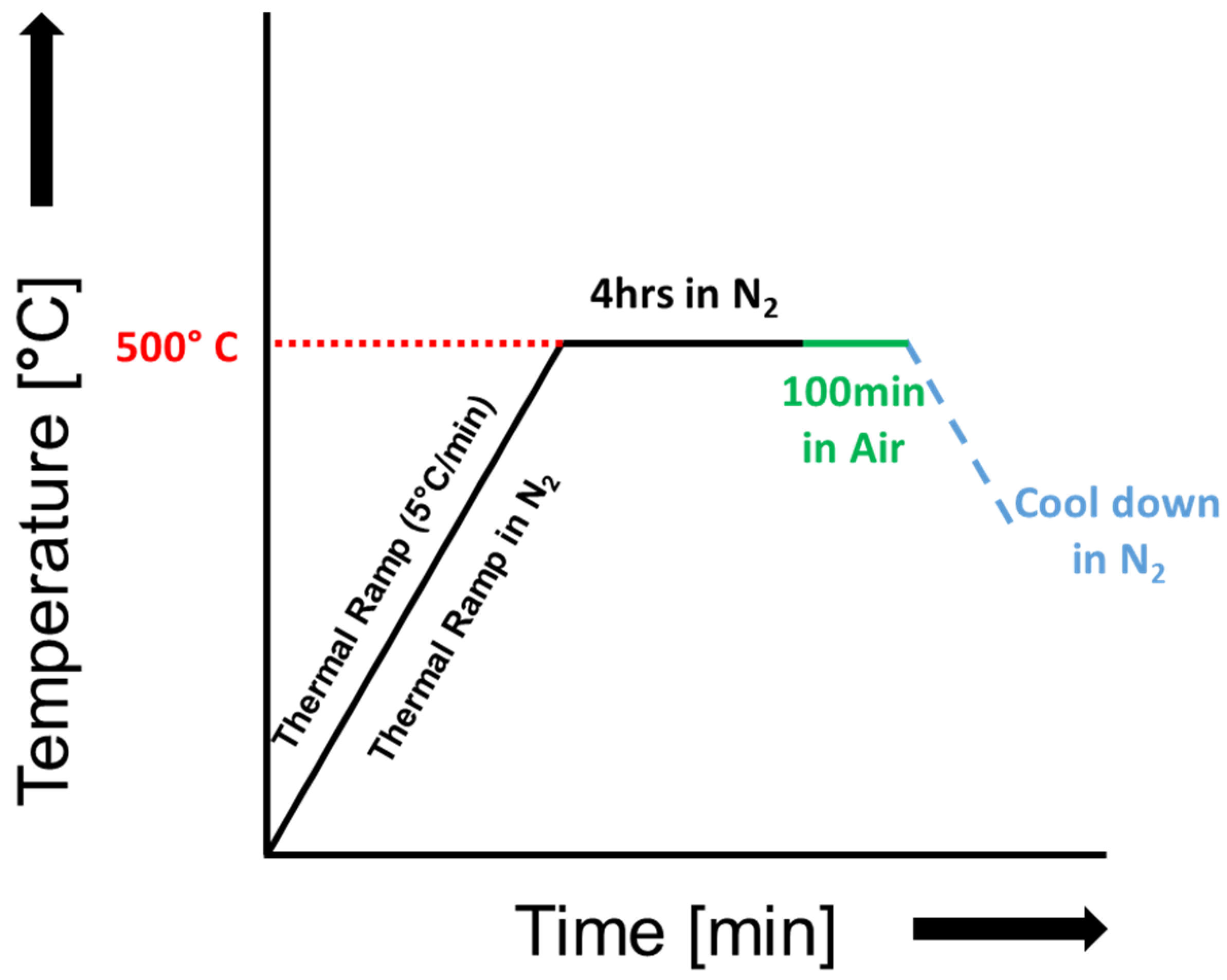
The “100-min” oxidation provided sufficient residue removal for full fiber separation in the dispersion test and is used in subsequent alignment and composite coupon fabrication tests. The cycle resulted in fiber degradation compared to virgin material strength (5228–5371 MPa) of about 16–26% depending on fibers tested from prepreg or long virgin fiber samples exposed and extracted from the GLO oven experiments. The optimized large-scale thermal cycle for the recovery of fibers from the prepreg scrap can be seen in Figure 8.

2.4. Composite Panel Processing and Analysis

100 g of short fiber prepreg material underwent the optimized thermal cycle with a “100-min” oxidation step, followed by alignment using the TuFF process. Virgin CF material was also processed. The processing quality of the produced preforms is shown in Figure 9, with effective dispersion of the fibers in the mix tank followed by alignment into the sheet produced for the virgin and recycled fibers. Fiber length measurements confirmed retention around the target 3 mm cut length.

2.4.1. C-Scan Analysis

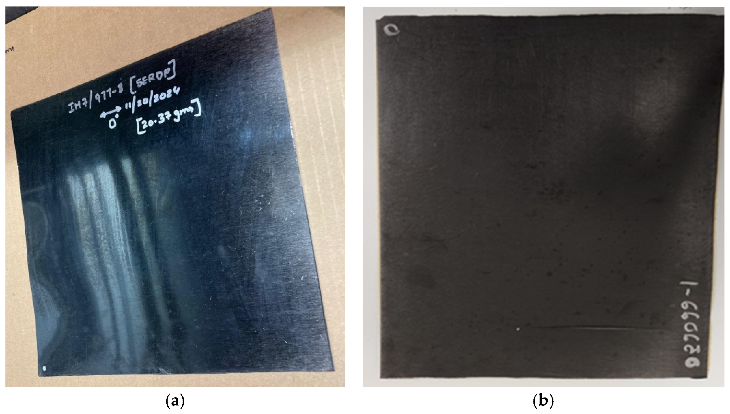
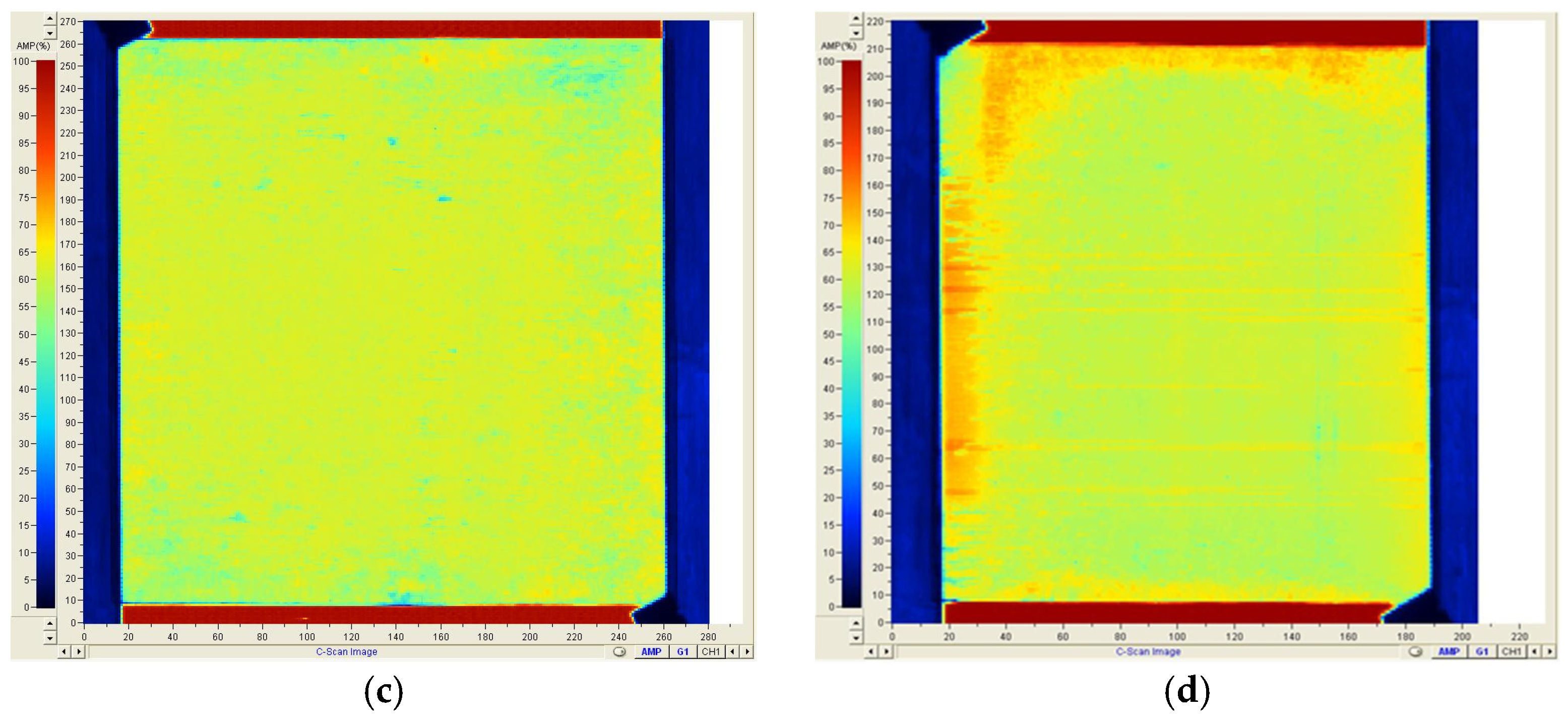
An ultrasonic C-scan evaluates panel consistency and quality. The processed virgin and recycled panels after prepregging and autoclave curing are shown in Figure 10a,b, with corresponding C-scans in Figure 10c,d. Panel edges were slightly dry due to resin loss at the panel edges, which is also indicative of the higher attenuation observed in the C-scan picture for recycled panels. No signs of internal voids or porosity were detected, which can be the result of higher autoclave pressures. Test samples were extracted from the interior, showing consistent quality.

2.4.2. Microscopy

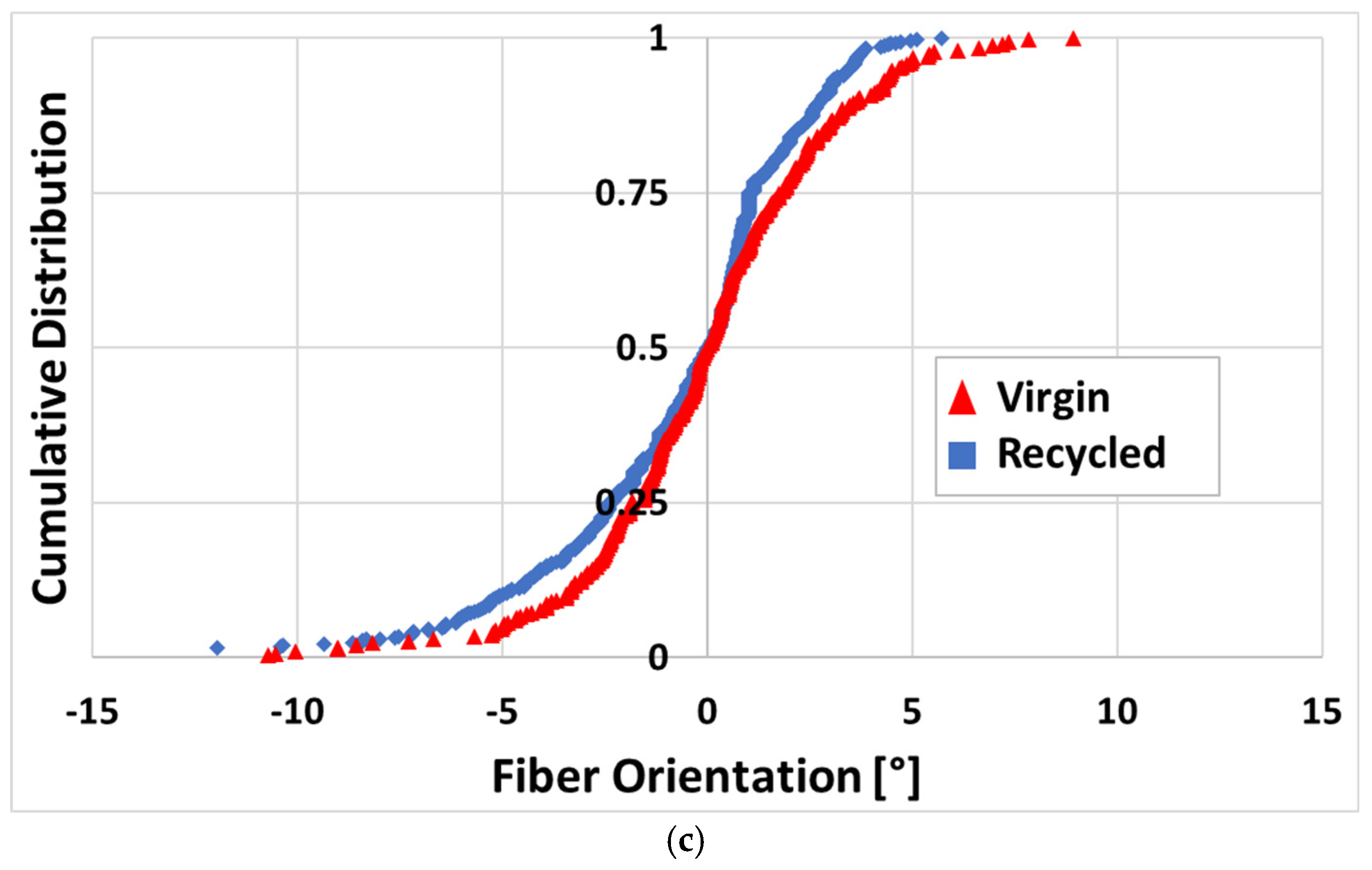
Cross-sectional microscopy further examined the panel quality and consistency, revealing high packing efficiency with no significant internal voids or resin-rich areas, validating the C-Scan analysis. The images can be seen in Figure 11a,b. Fiber orientation was evaluated with cross-sections cut at 75 degrees, major and minor axes of more than 200 fibers were measured, and the data was used to calculate and plot the fiber orientation distribution. The virgin fiber coupon exhibited good alignment quality, with 96% of all fibers within 5 degrees centered around the alignment direction. The fiber orientation of the recycled coupon showed a total of 93% of all fibers within 5 degrees, with most of the misaligned fibers located in one direction, as shown in Figure 11c.

2.4.3. Tensile Testing

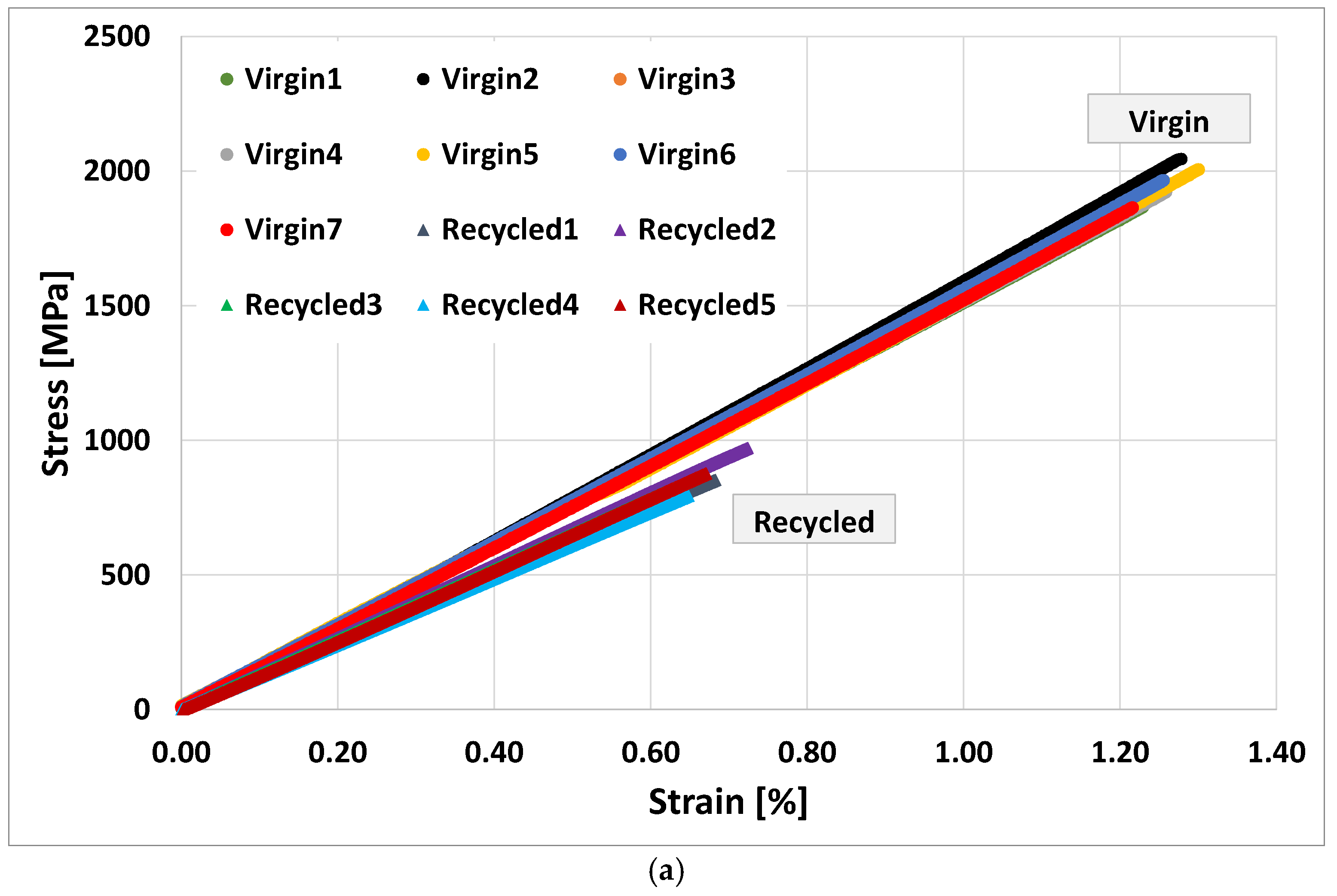
Test coupons were extracted from the processed panels and evaluated for their strengths and modulus translation. The stress-strain behavior is shown in Figure 12a. The measured tensile strength of 870 MPa ± 66 MPa and tensile modulus of 128 GPa ± 4.84 GPa indicate complete modulus translation compared to both the virgin continuous fiber prepreg material from the Hexel datasheet, normalized to 50% FVF and virgin TuFF composite as shown in Figure 12c. However, the strength translation showed a reduction of ~50% compared to virgin TuFF and ~55% compared to virgin continuous, which can be attributed to factors such as fiber degradation, loss of fiber/resin adhesion [31] and potential for some remaining agglomeration in the recycled TuFF preform. The virgin TuFF composite showed a small reduction in strength (7%) compared to the datasheet and might require longer fibers to improve stress translation between the discontinuous fiber material for this particular epoxy resin and sizing combination. This is also indicative of the complete non-explosive failure mode of the specimens, as seen in Figure 12b.

3. Materials and Methods

3.1. Materials

Cycom IM7/977-3 145 gsm (g/m2) unidirectional prepreg (resin weight content 33.5%) was procured from Syensqo. This prepreg combines intermediate modulus (IM7) carbon fiber with a toughened epoxy resin, capable of 350 °F (177 °C) dry and 270 °F (132 °C) wet service and is formulated for autoclave or press molding. Additionally, unsized IM7 fibers in tow form and 144 gsm 977-3 neat resin film were acquired for fiber degradation studies and reprocessing into rCFC from Hexel. Data sheets are available on the company’s websites [32,33]. The representative IM7/977-3 prepreg material is shown in Figure 13.

3.2. Methodology

The flowchart shown in Figure 14 outlines a systematic approach to optimize our composite recycling and processing. It begins with a Thermo-Gravimetric Analysis (TGA), optimizing thermal degradation and oxidation conditions to refine the recovery process. The methodology then advances to the scaling of the thermal cycle for fiber recovery, facilitating large-scale fiber reclamation, microstructural characterization via scanning electron microscopy (SEM), and mechanical assessment at the filament level. The final stage integrates recovered fibers into TuFF preform architectures for composite processing, testing and mechanical evaluation of both virgin and recycled composite systems.

3.3. Thermal Cycle Optimization

TGA assessed the degradation of resin and fiber in the prepreg, neat resin and virgin IM7 fibers during the pyrolysis and oxidation step, aimed at optimizing the fiber recovery process from the prepreg material. A dual gas environment was utilized, employing N2 for heating to degrade a portion of the resin (pyrolysis), followed by exposure to air for removal of polymer residue content (oxidation). This method minimizes the degradation of the carbon fibers while allowing maximum resin degradation [12,13,23,34]. The impact of the oxidation on fiber quality was assessed, and the process was scaled in a furnace to accommodate a larger quantity of prepreg material for subsequent TuFF and composite processing.

3.3.1. Non-Isothermal TGA

First, non-isothermal TGA analysis determined the temperature range to degrade the resin content in the pyrolysis step while securing the fiber strength quality. It is crucial to ensure that resin degradation occurs at lower temperatures, which has less of an effect on the fibers while being energy efficient. Non-isothermal runs were conducted with the neat resin, virgin IM7 and prepreg at a rate of 5 °C per minute from room temperature to 800 °C under N2 and air atmosphere. The temperature range is broad to capture the onset of polymer degradation while also allowing insight into fiber degradation at elevated temperatures. Full fiber degradation in air occurred below 800 °C and provided a good end point for TGA evaluation. Slower heating rates might provide a more rapid transition of weight loss vs. temperature and certainly could have been considered. Nevertheless, the information at 5 °C per min provided sufficient detail to select our temperatures for iso-thermal evaluation, reduced experimental time, and is an appropriate heating rate for larger-scale furnaces used during scale-up.

3.3.2. Isothermal TGA

Isothermal TGA results for the neat resin, virgin IM7 and prepreg were conducted at dwell temperatures of 450 °C, 500 °C, and 550 °C deduced from the non-isothermal data in both N2 and air environment to determine the optimal oxidation time. The material was heated to the dwell temperature under N2 (pyrolysis) and then switched to air (oxidation) during the dwell phase. This approach minimizes fiber degradation while allowing significant resin loss during heating, with up to 60% neat resin loss observed in the pyrolysis step. The prepreg material contains nominally 33.5% resin by weight, and the dwell cycle time must be minimized to achieve complete removal of the remaining resin content without leaving significant residue.

3.4. Scaling of Thermal Cycle for Fiber Recovery

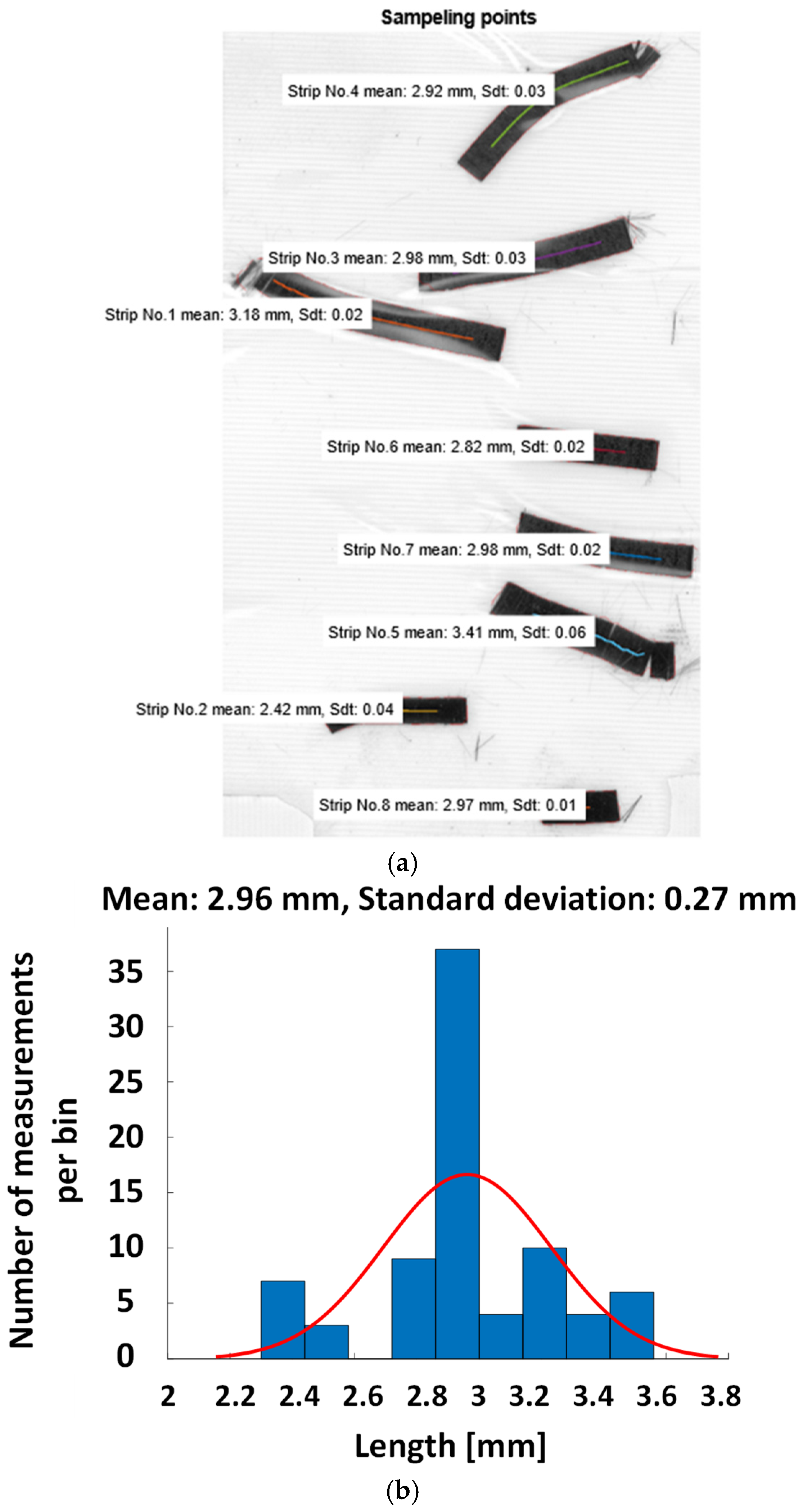
The prepreg material was cut into approximately 3 mm length strips using a guillotine paper cutter. A length of 3 mm has been previously shown to be sufficient for full property translation in TuFF composites compared to continuous fiber parts [35]. A high-resolution scanner (3200 dpi) scanned multiple strips simultaneously, and a script in MATLAB 2021b measured fiber length at 10 points on each strip. This cutting and scanning process was repeated for additional material as needed for composite processing in subsequent experiments. An average fiber length of 2.96 ± 0.27 mm was determined for ~80 cut samples. The cut prepreg material and length analysis are shown in Figure 15.
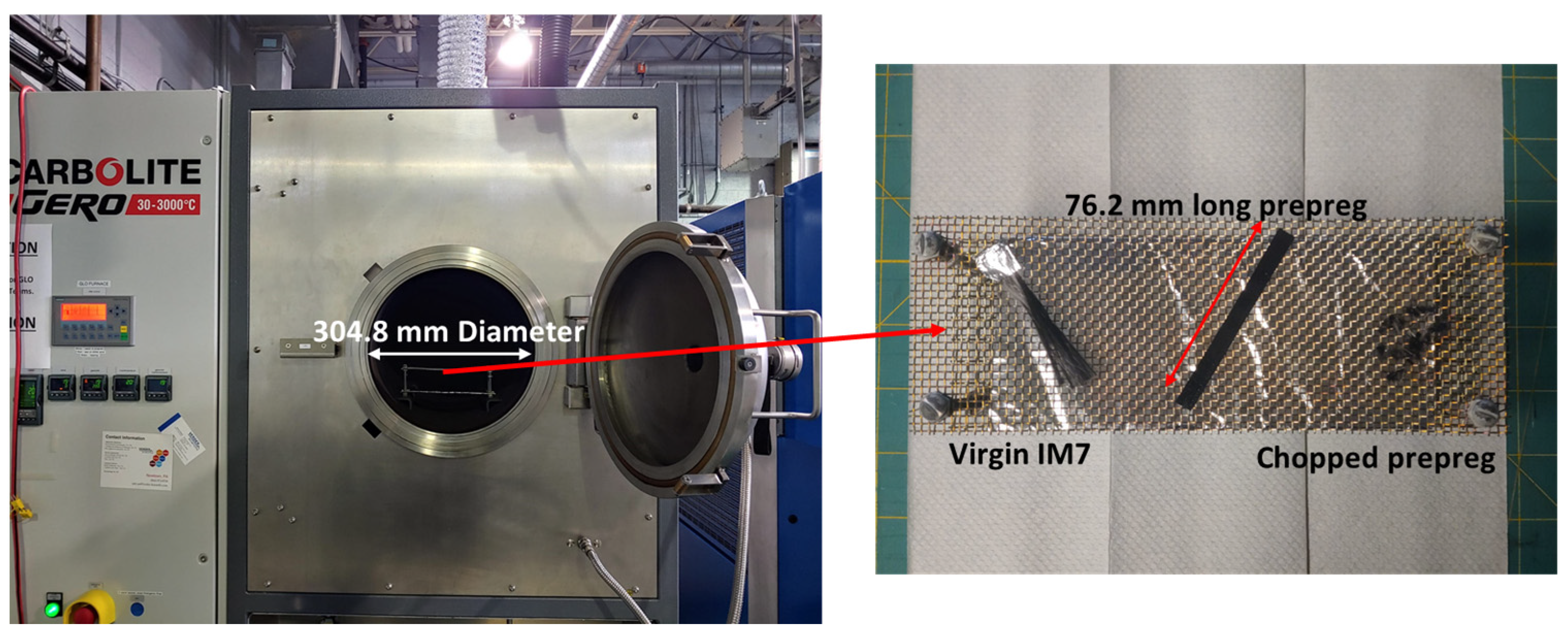
For large-scale recycling, a GLO 40/11-2G semi-automatic furnace from Carbolite Gero/Verder Scientific (Stuttgart/Germany) was employed, utilizing optimized thermal conditions obtained from TGA analysis. This furnace allows for precise control of the gas environment and heating cycle during the recycling process. Gas switching is automated, facilitating PID-controlled heating to the dwell temperature under N2, followed by exposure to air. Figure 16 illustrates the equipment and chamber, featuring a sample holder crafted from stainless steel mesh. The mesh, secured horizontally by four posts, possesses an opening of 10 × 10 per inch with a 0.635 mm wire diameter, resulting in an opened area of 56%, ensuring adequate gas exposure on both sides. Three input material formats are consistently maintained: chopped prepreg for investigations into recycling quality and surface characteristics and long fiber tows in both prepreg (~76 mm long) and unsized fiber (~62 mm long) form for studies on strength degradation.
The TGA results provided an initial setpoint for the dwell cycle (temperature and time) of the scaled thermal cycle to eliminate the polymer content in the prepreg while minimizing fiber loss and creating a cleaned fiber feedstock, allowing dispersion for the alignment process. The scaled process will require extending the dwell times compared to the TGA results due to (1) larger masses in the GLO oven leading to sample temperature and mass loss gradients and (2) variation of resin content in the prepreg sample with the dwell cycle having to eliminate worst case local higher resin content material.

3.4.1. Dispersion Analysis and Scanning Electron Microscopy

After each thermal cycle, dispersion analysis is conducted to evaluate filament-level dispersion quality, a critical factor for TuFF preforms processing. For every oxidation duration, dispersion is visually assessed, followed by SEM to examine fiber surface characteristics, providing key insights into dispersion quality at specific oxidation times. The study begins with no oxidation and progresses in increments up to 120 min, enabling a systematic evaluation of the effect of oxidation on fiber dispersion and surface quality of the recovered fibers.

3.4.2. Single Fiber Tension Test

The recovered fibers undergo strength evaluation to assess filament quality as a function of oxidation time. Testing samples are prepared with end tabs in small cassettes, ensuring precise alignment for mechanical testing. Prior to testing, fiber diameters are measured using confocal microscopy to account for dimensional variations. The fibers are then subjected to tensile testing using a “Diastron Tension Tester” at a standard gauge length of 12 mm as per ASTM C1577-20 standard [36], providing quantitative insights into their mechanical performance. The resulting data enables a comprehensive analysis of strength retention across different oxidation durations. An average of 40–60 samples are tested for each set for statistical consistency.

3.5. Composite Processing and Testing

3.5.1. TuFF Alignment Process

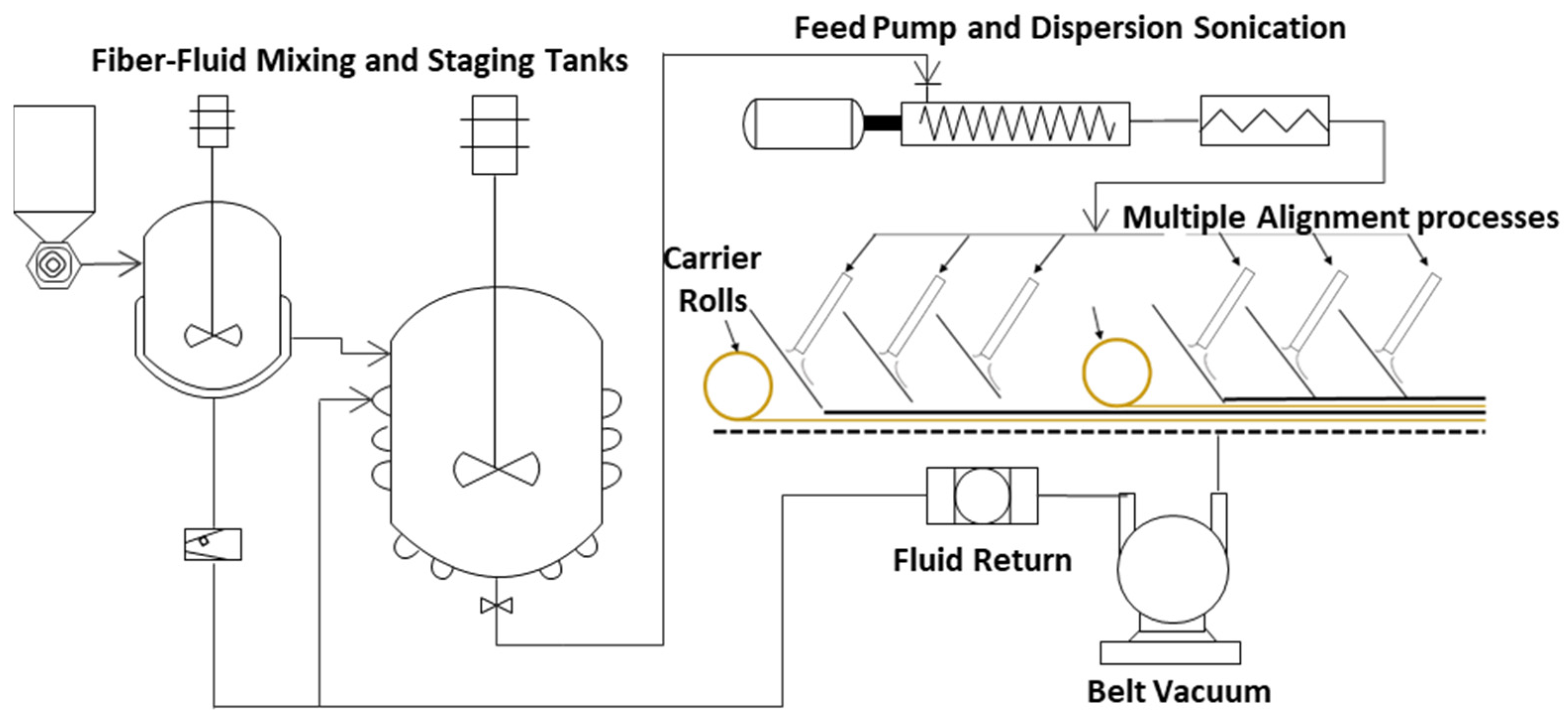
The TuFF process employs a fiber-fluid mixing system, including several staging tanks where fibers are dispersed at various dilution ratios. The fiber-water mix is pumped through a sonicator to break up any remaining agglomerates before the mixture is evenly spread on the sheet surface and deposited onto the porous belt. At the landing zone of the deposition belt surface, fibers undergo rapid rotation while fluid is extracted through the porous belt using a vacuum, resulting in the stabilization of the fiber material. The deposition sheet can be rotated to orient fibers at a wide range of angles relative to the belt travel direction, enabling the creation of tows, tapes, and sheets. A schematic of the overall process is shown in Figure 17, which consistently produces short fiber preforms that are highly aligned and densely packed [18,26,35].

3.5.2. Resin Film Impregnation and Curing Process

Composite panels were processed by initially prepregging the preforms using the resin film impregnation technique and cured in the autoclave as per the manufacturer’s cure cycle recommendation. Here, 24 layers of the nominal 8 gsm aligned sheets were stacked and combined with one 144 gsm resin layer added to the material. The expected FVF of the stack is approximately ~50%. An autoclave pressure of 200 psi (pounds per square inch) was applied to consolidate the material, which showed efficiency in suppressing any internal voids [37].

3.5.3. Ultrasonic C-Scan and Microscopy

Ultrasonic C-scan analysis was employed to assess laminate quality, utilizing a transducer and receiver system with water immersion for thorough inspection. A focused transducer was scanned in the X and Y directions, enabling defect detection for areas such as gaps, overlaps, voids, and porosity. Additionally, a VK-X250 3D Laser Scanning Confocal Microscope (SCM) (KEYENCE, Itasca, IL, USA) was used for high-resolution defect analysis within and between plies. Mid-section samples were cut, polished to 0.05 µm grit, and analyzed for FVF, void content, and orientation using ImageJ software (Fiji) [38]. Image stitching was performed to reconstruct defect regions, providing insights into their shape and size.

3.5.4. Mechanical Testing

Tensile testing was performed in accordance with ASTM D3039 [39], with test coupons precisely cut from the manufactured panels as per standard specifications. The tests were conducted on an Instron testing machine equipped with a 30 kN load cell, applying a loading rate of 2 mm per min. To minimize stress concentrations from the clamping system and prevent premature failure, 2 mm thick end tabs were bonded to each specimen using an epoxy adhesive. The gauge length was maintained constant at 250 mm. Strain measurements were captured using strain gauges bonded at the specimen center, which were connected to a strain acquisition system for real-time data collection. For each configuration, an average of five to six samples were tested to ensure statistical reliability.

4. Conclusions

This study demonstrated a multi-step optimization process for recovering fibers from IM7/977-3 prepreg through a combination of pyrolysis and oxidation process, subsequent fabrication of TuFF sheets, composite coupon production and mechanical testing. Despite a 25–30% reduction in fiber strength during the recycling process, effective dispersion enabled successful TuFF sheet conversion, allowing composite panel fabrication at ~50% FVF. Tensile tests showed full stiffness translation compared to both virgin continuous and virgin TuFF composites but a significant strength reduction, achieving 44% and 50% strength translation relative to virgin continuous and virgin TuFF composites, respectively. This strength reduction can be attributed to various factors. Firstly, a 25–30% decrease in composite strength directly correlates with fiber strength loss in the recovered carbon fiber material. Additionally, the 3 mm fiber length may not be sufficient for full-strength translation, given the fiber, adhesion and polymer combination. Other contributing factors may include the presence of a small number of connected filaments that are not fully dispersed, creating stress concentrations in the CFC. Future research will investigate and address those challenges in detail. Nevertheless, the properties exhibited by the recycled fiber composite with optimum thermal cycle reducing fiber degradation while allowing filament level dispersion surpassed previously reported values of rCFC [3], including recent advances using the HiPerDiF process with pyrolyzed CFs [40], marking a significant advancement in this field, as shown in Figure 18.

Author Contributions

Conceptualization: U.K.B., J.M.D., S.S. and D.H.; Data curation: U.K.B., A.G., T.O., L.F., S.S. and J.M.D.; Formal analysis: U.K.B., A.G., S.S. and L.F.; Funding acquisition: D.H.; Investigation: U.K.B., T.O., J.M.D. and D.H.; Methodology: U.K.B., A.G., T.O., C.B., M.D., L.F. and D.H.; Resources: A.G., C.B., M.D. and J.M.D.; Supervision: D.H.; Validation: A.G. and J.M.D.; Visualization: J.M.D.; Writing—original draft: U.K.B. and D.H.; Writing—review and editing: U.K.B., A.G., T.O., J.M.D. and D.H. All authors have read and agreed to the published version of the manuscript.

Funding

This material is based upon work supported by the Humphreys Engineer Center Support Activity under Contract No. W912HQ-P-0075. Views, opinions, and/or findings contained in this report are those of the author(s) and should not be construed as an official department of defense position or decision unless so designated by other official documentation.

Data Availability Statement

The data that support the findings of this study are available from the corresponding author upon reasonable request.

Acknowledgments

Special thanks to Neel Kher for support during data acquisition, Nicholas Shevchenko for C Scan Inspection and Edward Lake for support during autoclave processing. Also, Aydin Gunes extends his heartfelt gratitude to The Scientific and Technological Research Council of Turkey (TUBITAK) for his fellowship at the University of Delaware under project number 1059B192000152.

Conflicts of Interest

Composites Automation LLC is the licensee of the TuFF process reported in this study. Dirk Heider, the corresponding author of this paper is also the inventor of the TuFF process with patent number US11047078B2. The funding sponsors had no role in the design of the study; in the collection, analyses, or interpretation of data; in the writing of the manuscript, and in the decision to publish the results.

References

  1. Stieven Montagna, L.; Ferreira de Melo Morgado, G.; Lemes, A.P.; Roberto Passador, F.; Cerqueira Rezende, M. Recycling of carbon fiber-reinforced thermoplastic and thermoset composites: A review. J. Thermoplast. Compos. Mater. 2022, 36, 3455–3480. [Google Scholar]
  2. Oliveux, G.; Dandy, L.O.; Leeke, G.A. Current status of recycling of fibre reinforced polymers: Review of technologies, reuse and resulting properties. Prog. Mater. Sci. 2015, 72, 61–99. [Google Scholar] [CrossRef]
  3. Khurshid, M.F.; Hengstermann, M.; Hasan, M.M.B.; Abdkader, A.; Cherif, C. Recent developments in the processing of waste carbon fibre for thermoplastic composites–A review. J. Compos. Mater. 2020, 54, 1925–1944. [Google Scholar]
  4. Pakdel, E.; Kashi, S.; Varley, R.J.; Wang, X. Recent progress in recycling carbon fibre reinforced composites and dry carbon fibre wastes. Resour. Conserv. Recycl. 2020, 166, 105340. [Google Scholar] [CrossRef]
  5. Bao, L.; Sun, Y.; Ruan, F.; Murakami, Y.; Yu, Y. Development of a method for recycling factory waste carbon fiber prepregs and increasing the added value of the collected material. Polym. Compos. 2023, 44, 2071–2079. [Google Scholar]
  6. Naqvi, S.R.; Prabhakara, H.M.; Bramer, E.; Dierkes, W.K.; Akkerman, R.; Brem, G. A critical review on recycling of end-of-life carbon fibre/glass fibre reinforced composites waste using pyrolysis towards a circular economy. Resour. Conserv. Recycl. 2018, 136, 118–129. [Google Scholar]
  7. Salas, A.; Berrio, M.E.; Martel, S.; Díaz-Gómez, A.; Palacio, D.A.; Tuninetti, V.; Medina, C.; Meléndrez, M.F. Towards recycling of waste carbon fiber: Strength, morphology and structural features of recovered carbon fibers. Waste Manag. 2023, 165, 59–69. [Google Scholar] [CrossRef]
  8. Hagnell, M.K.; Åkermo, M. The economic and mechanical potential of closed loop material usage and recycling of fibre-reinforced composite materials. J. Clean. Prod. 2019, 223, 957–968. [Google Scholar] [CrossRef]
  9. Pimenta, S.; Pinho, S.T. Recycling carbon fibre reinforced polymers for structural applications: Technology review and market outlook. Waste Manag. 2011, 31, 378–392. [Google Scholar] [CrossRef]
  10. Fitzgerald, A.M.; Wong, N.; Fitzgerald, A.; Jesson, D.A.; Martin, F.; Murphy, R.J.; Young, T.; Hamerton, I.; Longana, M.L. Life Cycle Assessment of the High Performance Discontinuous Fibre (HiPerDiF) Technology and Its Operation in Various Countries. Sustainability 2022, 14, 1922. [Google Scholar] [CrossRef]
  11. Guo, W.; Bai, S.; Ye, Y.; Zhu, L. Recycling carbon fiber-reinforced polymers by pyrolysis and reused to prepare short-cut fiber C/C composite. J. Reinf. Plast. Compos. 2019, 38, 340–348. [Google Scholar]
  12. López, F.A.; Rodríguez, O.; Alguacil, F.J.; García-Díaz, I.; Centeno, T.A.; García-Fierro, J.; González, C. Recovery of carbon fibres by the thermolysis and gasification of waste prepreg. J. Anal. Appl. Pyrolysis 2013, 104, 675–683. [Google Scholar] [CrossRef]
  13. Kim, H.H.; Kim, B. Recovery of carbon fibers from carbon fiber-reinforced epoxy-isophorone diamine composites via step thermolysis. Compos. Part B Eng. 2023, 260, 110757. [Google Scholar]
  14. Lopez-Urionabarrenechea, A.; Gastelu, N.; Acha, E.; Caballero, B.M.; Orue, A.; Jiménez-Suárez, A.; Prolongo, S.; Marco, I.D. Reclamation of carbon fibers and added-value gases in a pyrolysis-based composites recycling process. J. Clean. Prod. 2020, 273, 123173. [Google Scholar]
  15. Hanaoka, T.; Ikematsu, H.; Takahashi, S.; Ito, N.; Ijuin, N.; Kawada, H.; Arao, Y.; Kubouchi, M. Recovery of carbon fiber from prepreg using nitric acid and evaluation of recycled CFRP. Compos. Part B Eng. 2022, 231, 109560. [Google Scholar] [CrossRef]
  16. Karuppannan Gopalraj, S.; Kärki, T. A Study to Investigate the Mechanical Properties of Recycled Carbon Fibre/Glass Fibre-Reinforced Epoxy Composites Using a Novel Thermal Recycling Process. Processes 2020, 8, 954. [Google Scholar] [CrossRef]
  17. Such, M.C.; Ward, C.; Potter, K. Aligned Discontinuous Fibre Composites: A Short History. J. Multifunct. Compos. 2014, 2, 113–126. [Google Scholar] [CrossRef]
  18. Tierney, J.J.; Crane, R.M.; Blackwell, C. Short Fiber TuFF Technology for Automotive Part Production via Wet Compression. In Proceedings of the SAMPE 2022, Charlotte, NC, USA, 23 May 2022. [Google Scholar]
  19. Yu, H.; Potter, K.; Wisnom, M.R. A novel manufacturing method for aligned discontinuous fibre composites (High Performance-Discontinuous Fibre method). Compos. Part A Appl. Sci. Manuf. 2014, 65, 175–185. [Google Scholar] [CrossRef]
  20. Aravindan, P.; Becagli, F.; Longana, M.L.; Blok, L.G.; Pozegic, T.R.; Huntley, S.J.; Rendall, T.C.; Hamerton, I. Remanufacturing of Woven Carbon Fibre Fabric Production Waste into High Performance Aligned Discontinuous Fibre Composites. J. Compos. Sci. 2020, 4, 68. [Google Scholar] [CrossRef]
  21. Longana, M.L.; Yu, H.; Potter, K. The High Performance Discontinuous Fibre (HiPerDiF) Method for the Remanu-facturing of Mixed Length Rreclaimed Carbon Fibres. In Proceedings of the 21st International Conference on Composite Materials, Xi’an, China, 20–25 August 2017. [Google Scholar]
  22. Longana, M.L.; Ong, N.; Yu, H.; Potter, K. Multiple closed loop recycling of carbon fibre composites with the HiPerDiF (High Performance Discontinuous Fibre) method. Compos. Struct. 2016, 153, 271–277. [Google Scholar] [CrossRef]
  23. Tapper, R.J.; Longana, M.L.; Yu, H.; Hamerton, I.; Potter, K. Development of a closed-loop recycling process for discontinuous carbon fibre polypropylene composites. Compos. Part B Eng. 2018, 146, 222–231. [Google Scholar] [CrossRef]
  24. Hamerton, I.; Sullivan, P.; Eichhorn, S.; Summers, V. Influence of Fibre Length Distribution on the Processing of Aligned Discontinuous Reclaimed Carbon Fibre Material. In Proceedings of the SAMPE 2024, Long Beach, CA, USA, 20–23 May 2024. [Google Scholar] [CrossRef]
  25. Turner, T.A.; Warrior, N.A.; Pickering, S. Development of high value moulding compounds from recycled carbon fibres. Plast. Rubber Compos. 2010, 39, 151–156. [Google Scholar] [CrossRef]
  26. Ozdemir, T.; Deitzel, J.M.; Crane, R.; Yarlagadda, S.; Blackwell, C.; Davis, M.; Emmerich, R.; Heider, D. Carbon Fiber Composites Recycling Technology Enabled by the TuFF Technology. Recycling 2024, 9, 11. [Google Scholar] [CrossRef]
  27. He, D.; Soo, V.K.; Stojcevski, F.; Lipiński, W.; Henderson, L.C.; Compston, P.; Doolan, M.C. The effect of sizing and surface oxidation on the surface properties and tensile behaviour of recycled carbon fibre: An end-of-life perspective. Compos. Part A Appl. Sci. Manuf. 2020, 138, 106072. [Google Scholar]
  28. Mazzocchetti, L.; Benelli, T.; D’Angelo, E.; Leonardi, C.; Zattini, G.; Giorgini, L. Validation of carbon fibers recycling by pyro-gasification: The influence of oxidation conditions to obtain clean fibers and promote fiber/matrix adhesion in epoxy composites. Compos. Part A Appl. Sci. Manuf. 2018, 112, 504–514. [Google Scholar] [CrossRef]
  29. Feih, S.; Mouritz, A.P.; Case, S.W. Determining the mechanism controlling glass fibre strength loss during thermal recycling of waste composites. Compos. Part A Appl. Sci. Manuf. 2015, 76, 255–261. [Google Scholar] [CrossRef]
  30. Xu, M.; Meng, X.; Ji, H.; Yang, J.; Di, J.; Wu, Y.; Lu, Q. Evolution of pyrolysis char during the recovery of carbon fiber reinforced polymer composite and its effects on the recovered carbon fiber. J. Environ. Chem. Eng. 2024, 12, 112214. [Google Scholar]
  31. Chen, B.R.; Parambil, N.K.; Deitzel, J.M.; Gillespie, J.W.; Vo, L.T.; Sarosi, P.M. Interfacial Shear Strength (IFSS) and Absorbed Energy Versus Temperature in Carbon Fiber-Thermoplastic Composites via Single Fiber Pullout Testing. In Proceedings of the American Society for Composites—Thirty-Fifth Technical Conference, Virtual, 14–17 September 2020. [Google Scholar]
  32. Cycom Cytec 977-3. 2022. Available online: www.solvay.com (accessed on 1 July 2024).
  33. HexTow® IM7 Carbon Fiber. 2023. Available online: http://www.hexcel.com (accessed on 1 July 2024).
  34. Chen, S.; Cao, X.; Zu, L.; He, J.; Zhang, Q.; Ren, P.; Zhang, G.; Wu, Q.; Fu, J.; Zhou, L. Optimisation of recycling process parameters of carbon fibre in epoxy matrix composites. Compos. Struct. 2023, 315, 116995. [Google Scholar] [CrossRef]
  35. Yarlagadda, S.; Deitzel, J.M.; Heider, D.; Tierney, J.J.; Gillespie, J. Tailorable Universal Feedstock for Forming (TUFF): Overview and Performance. In Proceedings of the SAMPE 2019, Charlotte, NC, USA, 20–23 May 2019. [Google Scholar]
  36. ASTM C1557-20; Standard Test Method for Tensile Strength and Young’s Modulus of Fibers. ASTM International: West Conshohocken, PA, USA, 2020. [CrossRef]
  37. Balaga, U.K.; Gargitter, V.; Crane, R.M.; Tierney, J.C.; Yarlagadda, S.; Heider, D.; Advani, S.G. Characterization and comparison of thin ply IM7/8552 composites processed by automated tape placement and hand layup. J. Compos. Mater. 2023, 57, 2243–2260. [Google Scholar] [CrossRef]
  38. Schindelin, J.; Arganda-Carreras, I.; Frise, E.; Kaynig, V.; Longair, M.; Pietzsch, T.; Preibisch, S.; Rueden, C.; Saalfeld, S.; Schmid, B.; et al. Fiji: An open-source platform for biological-image analysis. Nat. Methods 2012, 9, 676–682. [Google Scholar] [CrossRef]
  39. ASTM D3039/D3039M-17; Standard Test Method for Tensile Properties of Polymer Matrix Composite Materials. ASTM International: West Conshohocken, PA, USA, 2017. [CrossRef]
  40. Hecker, M.D.; Longana, M.L.; Eloi, J.; Thomsen, O.T.; Hamerton, I. Recycling end-of-life sails by carbon fibre reclamation and composite remanufacture using the HiPerDiF fibre alignment technology. Compos. Part A Appl. Sci. Manuf. 2023, 173, 107651. [Google Scholar] [CrossRef]
Figure 1. (a) Chopped fiber strands, (b) Short fiber random mats.
Recycling 10 00055 g001
Figure 2. Non-isothermal run to 800 °C in N2 and Air.
Recycling 10 00055 g002
Figure 3. Isothermal runs at (a) 450 °C in N2 followed by oxidation in the air for 6 h, (b) 500 °C in N2 followed by oxidation in the air for 2 h, (c) 550 °C in N2 followed by oxidation in the air for 2 h.
Recycling 10 00055 g003aRecycling 10 00055 g003b
Figure 4. IM7 weight loss for specific dwell temperature/time combinations.
Recycling 10 00055 g004
Figure 5. Visualization of dispersion for (a) ISO–1, (b) ISO–3, (c) ISO–5, (d) ISO–7, (e) ISO–9, (f) ISO–11.
Recycling 10 00055 g005
Figure 6. SEM images of recovered fibers for (a) ISO–1, (b) ISO–3, (c) ISO–5, (d) ISO–7, (e) ISO–9, (f) ISO–11.
Recycling 10 00055 g006aRecycling 10 00055 g006b
Figure 7. Graphical representation of the degradation trend.
Recycling 10 00055 g007
Figure 8. Optimized thermal cycle for efficient fiber recovery.
Recycling 10 00055 g008
Figure 9. (a) Virgin IM7 TuFF preform, (b) rCF TuFF preform.
Recycling 10 00055 g009
Figure 10. (a) Processed virgin composite panel (10″ × 10″), (b) Processed recycled composite panel (10″ × 10″), (c) Virgin composite C-Scan, (d) Recycled composite C-Scan.
Recycling 10 00055 g010aRecycling 10 00055 g010b
Figure 11. (a) Cross-sectional microscopy of virgin composite, (b) Cross-sectional microscopy of recycled composite, (c) Orientation analysis.
Recycling 10 00055 g011aRecycling 10 00055 g011b
Figure 12. (a) Representative Stress-Strain curve of tested samples, (b) Failure mode showing a mix of both catastrophic and axial splitting (left virgin, right recycled), (c) Property comparison plot, strength (blue) and modulus (orange).
Recycling 10 00055 g012aRecycling 10 00055 g012b
Figure 13. Representative prepreg material.
Recycling 10 00055 g013
Figure 14. Flow chart of optimization methodology.
Recycling 10 00055 g014
Figure 15. Chopped prepreg material length analysis. (a) Example of cut prepreg pieces, software detecting the samples representation and (b) Length distribution of ~80 samples.
Recycling 10 00055 g015
Figure 16. GLO furnace and sample holder, as well as enlarged samples for better visual representation.
Recycling 10 00055 g016
Figure 17. Schematic of TuFF process.
Recycling 10 00055 g017
Figure 18. Comparison to data reported in the literature [3,40].
Recycling 10 00055 g018
Table 1. Dwell time to achieve 33% prepreg loss for different dwell temperatures.
450 °C500 °C550 °C
3% Resin residueIM7 loss [%]3.30.71.0
IM7 loss rate [%/min]−0.02−0.02−0.05
Time in dwell [min]1635724
2% Resin residueIM7 loss [%]4.11.01.2
IM7 loss rate [%/min]−0.03−0.02−0.06
Time in dwell [min]1977129
1% Resin residueIM7 loss [%]6.11.61.6
IM7 loss rate [%/min]−0.03−0.02−0.07
Time in dwell [min]2589635
Table 2. Thermal runs ID (ISO stands for Isothermal).
IDMaterialPyrolysisOxidation
ISO–1Prepreg (IM7/977-3)500 °C for 4 h in N2500 °C for 0 min in Air
ISO–2Virgin IM7500 °C for 4 h in N2500 °C for 0 min in Air
ISO–3Prepreg (IM7/977-3)500 °C for 4 h in N2500 °C for 60 min in Air
ISO–4Virgin IM7500 °C for 4 h in N2500 °C for 60 min in Air
ISO–5Prepreg (IM7/977-3)500 °C for 4 h in N2500 °C for 70 min in Air
ISO–6Virgin IM7500 °C for 4 h in N2500 °C for 70 min in Air
ISO–7Prepreg (IM7/977-3)500 °C for 4 h in N2500 °C for 80 min in Air
ISO–8Virgin IM7500 °C for 4 h in N2500 °C for 80 min in Air
ISO–9Prepreg (IM7/977-3)500 °C for 4 h in N2500 °C for 100 min in Air
ISO–10Virgin IM7500 °C for 4 h in N2500 °C for 100 min in Air
ISO–11Prepreg (IM7/977-3)500 °C for 4 h in N2500 °C for 120 min in Air
ISO–12Virgin IM7500 °C for 4 h in N2500 °C for 120 min in Air
Table 3. Strength degradation as a function of increased oxidation time.
Thermal CycleStrength [MPa]St. Deviation [MPa]Degradation [%]
ISO–152288125
ISO–2537110253
ISO–3446385219
ISO–4488776711
ISO–5437287521
ISO–6473578214
ISO–7416876124
ISO–8465691916
ISO–9405545226
ISO–10460853116
ISO–11371576233
ISO–12455095418
Disclaimer/Publisher’s Note: The statements, opinions and data contained in all publications are solely those of the individual author(s) and contributor(s) and not of MDPI and/or the editor(s). MDPI and/or the editor(s) disclaim responsibility for any injury to people or property resulting from any ideas, methods, instructions or products referred to in the content.