Article

Comparison of Different Current Collector Materials for In Situ Lithium Deposition with Slurry-Based Solid Electrolyte Layers

Electrical Energy Storage Systems, Institute for Photovoltaics, University of Stuttgart, Pfaffenwaldring 47, 70569 Stuttgart, Germany
*
Author to whom correspondence should be addressed.
Batteries 2023, 9(8), 412; https://doi.org/10.3390/batteries9080412
Submission received: 22 June 2023 / Revised: 29 July 2023 / Accepted: 5 August 2023 / Published: 7 August 2023

Abstract

:
In this paper, we investigate different current collector materials for in situ deposition of lithium using a slurry-based β -Li3PS4 electrolyte layer with a focus on transferability to industrial production. Therefore, half-cells with different current collector materials (carbon-coated aluminum, stainless steel, aluminum, nickel) are prepared and plating/stripping tests are performed. The results are compared in terms of Coulombic efficiency (CE) and overvoltages. The stainless steel current collector shows the best performance, with a mean efficiency of η mean , SST = 98 % ; the carbon-coated aluminum reaches η mean , Al + C = 97 % . The results for pure aluminum and nickel indicate strong side reactions. In addition, an approach is tested in which a solvate ionic liquid (SIL) is added to the solid electrolyte layer. Compared to the cell setup without SIL, this cannot further increase the CE; however, a significant reduction in overvoltages is achieved.

1. Introduction

Today, lithium-ion cells are used for energy storage systems in many mobile and stationary applications. The demands on energy and power densities of these storage systems are constantly growing and require new cell technologies. Likewise, safety aspects are frequently raised, mainly related to the flammability of the organic liquid electrolytes currently in use. Lithium (Li) in metallic form, with a theoretical capacity of c Li = 3860 mAh g and a strongly negative electrochemical potential of E Li 0 = 3.04 V against the standard hydrogen electrode, offers the possibility to increase energy density by replacing the graphite electrode ( c C 6 = 372 mAh g ) on the anode side [1,2,3]. However, using metallic lithium presents some challenges: repeated charging and discharging of lithium metal cells leads to needle-shaped lithium structures (dendrites) on the electrode surface. Combined with a liquid electrolyte, this leads to a constant reformation of the solid electrolyte interface (SEI), ultimately resulting in the loss of active material and a high consumption of the liquid electrolyte. In addition, dendrite growth can cause internal cell short circuits, which are associated with the thermal runaway of the cell [4,5]. One way to counteract this behavior is to use a solid electrolyte (SE), which can limit dendrite growth due to the material’s properties. In summary, the energy density and safety of energy storage devices could be increased, for example, by using Li anodes and solid electrolytes (SEs) [6,7,8].
SEs can be divided into several classes, with sulfide-based solid electrolytes showing a high ionic conductivity of lithium ions (Li + ) in the range of κ = 10 3 to 10 2 s cm [9,10,11]. Many publications show promising results when using this group of electrolytes [12,13,14,15]. However, current research is trying to cope with different challenges, among which the use of a pure lithium metal electrode is one. Another challenge is preparing the solid electrolyte layer on a manufacturing scale. These challenges will be discussed in more detail in the following subsections. It is important to note that all of the approaches investigated in this paper are compatible with upscaling for mass production.

1.1. Lithium Metal Electrode

Contrary to many assumptions, using solid electrolytes does not solve all of the issues previously observed for lithium metal electrodes with liquid electrolytes. Strong side reactions in the form of electrolyte decomposition and the consumption of active lithium still appear. This behavior is due to the electrochemical stability window of the electrolyte and the very low redox potential of Li metal [16]. This side reaction forms the SEI, which prevents direct contact between the electrolyte and the Li electrode. However, volume changes due to lithium deposition and re-deposition repeatedly cause the SEI to break up and reform. This process amplifies the uneven deposition of Li, leading to dendrite growth [17]. The growth of dendrites through the solid electrolyte layer can be observed along the electrolyte particle boundaries, which can result in a short circuit [18]. Another challenge is the loss of contact between the electrolyte layer and the electrode [19]. All these effects severely limit the lifetime of cells with lithium metal anodes and (sulfide-based) solid electrolytes [15,20].
There are different approaches to improving the cycling behavior of lithium electrodes combined with SEs. For this, it is important to distinguish between two types of lithium electrodes [21]:
(1) The electrode itself consists of a thin layer of lithium and represents a reservoir of lithium in the cell. This design has the advantage that the amount of available Li and, thus, the cell capacity does not decrease too quickly due to lithium consumption by side reactions [22]. However, the Li reservoir reduces the cell’s energy density, and the processing of metallic lithium poses major challenges in production. On the other hand, the ductility of the Li can be used to establish and maintain contact with the electrolyte layer by pressing the Li onto it.
(2) The second type of electrode is called anode-free, as the amount of cyclable Li originates only from the positive electrode. There is no lithium reservoir in the cell and lithium is deposited in situ on the current collector. As a result, the total cell capacity decreases in the presence of strong side reactions [23] and cannot be compensated for by excess Li. However, such a setup with in situ deposition offers significant production advantages. For example, the solid electrolyte layer can be applied directly to the negative current collector, and the safety risks of using metallic lithium in production are reduced significantly [24]. However, very good contact between the electrolyte layer and the current collector must be ensured for the subsequent function of the cell.
The simplest current collector variant is planar metal foil. In contrast to conventional lithium-ion cells, no copper (Cu) current collector can be used on the negative electrode side since the combination with sulfidic electrolytes forms copper sulfide ( Cu 7 S 4 ), leading to corrosion of the current collector [13,25]. Alternatives are, for example, stainless steel (SST), aluminum (Al), nickel (Ni), and carbon [26]. SST is chemically more stable with sulfides than Cu, as Homann et al. show in [25]. The successful use of a nickel-containing current collector is shown in [27]. In the mentioned publication, a planar nickel foil does not provide the best cycling results in comparison, but it can be a good option for in situ lithium deposition because nickel does not form an alloy with lithium [28]. However, there is the possibility of nickel oxide or nickel sulfide formation, which could improve the cycle behavior, but could also have the opposite effect [26].
Aluminum, on the other hand, forms an alloy with Li, and this effect can be used to improve the cycling behavior of Li electrodes [29]. The objectives are to reduce the activity of the metallic lithium by alloy formation and to increase the electrode potential, which should minimize the progressive electrolyte decomposition. However, several investigations with liquid electrolytes show poor cycling stabilities [29]. Pan et al. show in [30] promising results using a Li-Al alloy and the solid sulfide electrolyte Li 10 GeP 2 S 12 .
In addition to pure metal foils, coated current collectors can also be used for the negative electrode. Carbon-coated aluminum foils are available on the market, as these are already used in Li-ion cells on the positive electrode side. Here, they are mainly used to achieve strong adhesion and good electrical contact between the current collector and the active material [31]. In this paper, a carbon-coated Al foil will also be investigated for its suitability for lithium deposition, since carbonaceous coatings have been associated with improved cycling performance in many publications [26,32,33].

1.2. SE Layer (Suitable for Production Scale)

In consideration of upscaling for mass production of SE layers, developments are moving towards slurry-based electrolyte layers. This allows existing know-how and production technologies to be used, which are already established for the commercialization of lithium-ion cells. For this purpose, the solid electrolyte in powder form is mixed with a binder and solvent to form a coating paste. In the subsequent application onto an electrode band, transfer foil or a current collector material with a slot die, the well-known roll-to-roll process, can be used. In the drying step, the solvent is evaporated, and the finished solid electrolyte layer can be further processed [21,34].
However, Oh et al. show in [35] that binders interrupt the Li + -ionic contacts between the solid electrolyte particles, which lowers the ionic conductivity of the electrolyte layer. As a remedy, they add a solvate ionic liquid (SIL) that is intended to create ion-conducting bridges within the binder phase between the electrolyte particles. This approach is adopted in this paper with not only the aim of increasing the ionic conductivity of the electrolyte layer but also to achieve more homogeneous lithium deposition. A graphical illustration of this hypothesis can be found in Figure 1. It shows a schematic cross-section through the contact area between the slurry-based solid electrolyte layer and the current collector, on which Li is to be deposited. Looking at Figure 1a, the electrolyte particles (yellow circles) are enclosed with ionically insulating binder (illustrated in blue), resulting in few direct contact points between the current collector and SE. This leads to a small number of ionically conductive paths towards the current collector for lithium deposition (green). This takes place unevenly at scattered locations (marked in orange). The addition of an SIL to the electrolyte layer (Figure 1b) causes the binder to swell (illustrated in pink) and establish ionically conductive connections between the individual particles (marked in red) and to the current collector. As a result, there are more paths for Li + -ions towards the current collector, whereby the SSE layer’s overall resistance is decreased, and lithium deposition occurs more evenly distributed over its surface (marked in orange).
As the SIL lithium triglyme bis(trifluoromethanesulfonyl)imide (from now on referred to as [ Li ( G 3 ) ] TFSI ) is used in [35], this SIL is selected and will be investigated for its suitability for improving Li metal half-cells with the solid electrolyte lithium phosphorus sulfide β -Li3PS4 (LPS).
If we look at the phase boundary between a Li electrode and sulfidic electrolytes, surface layers with different properties are formed there depending on the type of electrolyte. This paper will focus on β -Li3PS4, which mainly leads to an SEI consisting of Li 2 S and Li 3 P . This side reaction can be described as follows: Li3PS4 + 8Li → 4Li2S + Li3P [36]. The reaction product Li2S is electrically as well as ionically insulating and stable at V = 0 V versus (vs.) Li/ Li + [16,37]. Li3P is also thermodynamically stable against Li metal and known for high Li + -conductivity and mechanical strength [37,38]. In [39], this type of SEI composition is described: “stable and ideal interfaces formed when the solid-state electrolyte (SSE) does not electrochemically react with the Li metal”.
In this paper, approaches suitable for commercial production are compared experimentally, focusing on in situ lithium deposition on the anode side. For this purpose, half-cells with different current collectors, and half-cells with the solvate ionic liquid [ Li ( G 3 ) ] TFSI in the SE-layer are set up, electrochemically investigated, and compared.

2. Experimental

The production of the electrolyte slurry and the subsequent steps up to the finished half-cells take place in an argon-filled glove box (LABstar by MBraun, Garching, Germany). All solid components are dried in a vacuum oven (B-580 by BÜCHI Labortechnik GmbH, Essen, Germany) for at least t dry = 16 h before processing. Solvents are dried with the help of molecular sieves with a pore size of p = 3 Å .

2.1. Materials

The production of the electrolyte layers is slurry based, using β -Li3PS4 powder produced by IoLiTec Ionic Liquids Technologies GmbH (Heilbronn, Germany), hydrogenated nitrile-butadiene rubber (HNBR) from ARLANXEO Holding B.V. (Den Haag, The Netherlands) as binder, and p-xylene purchased from Supelco Sigma-Aldrich Chemie GmbH (Darmstadt, Germany) as solvent. The HBNR is dissolved in p-xylene to obtain a binder solution with ω binder = 5 wt . % . For slurry production, m BS = 2 g of this solution is mixed with m Xylene = 1.1 g of p-xylene and m LPS = 1.9 g to obtain a solid content of ω = 40 wt . % . For the mixing process, the slurry-filled container is sealed and taken out of the glove box to be mixed in a planetary mixer Thinky ARE-250 (C3 Prozess- und Analysentechnik GmbH, Haar, Germany). The electrolyte layer is coated onto different metal foils using a doctor blade (PG-031-150, Thierry GmbH, Stuttgart, Germany) with a gap height of h = 400 μ m . The composition of the final SE layer is ω LPS = 95 wt . % LPS and ω HNBR = 5 wt . % HNBR.
For the variation of the current collector, the following metal foils are used: stainless steel 1.4310 (thickness h SST = 10 μ m ), aluminum 3.0205 (thickness h Al = 25 μ m ), nickel 2.4068 (thickness h Ni = 10 μ m )—all purchased from H&S Präzisionsfolien (Vohenstrauss, Germany). The carbon-coated Al foil from Xiamen Lith Machine Limited (Xiamen City, China) has a thickness of h AlC = 15 μ m with a coating thickness h C = 1 μ m .
For layers with solvate ionic liquid, [ Li ( G 3 ) ] TFSI is added to the finished slurry and remixed to obtain a final layer composition of ω LPS = 91.5 wt . % LPS, ω SIL = 3.5 wt . % IL, and ω HNBR = 5 wt . % HNBR. The SIL-containing slurry is processed as described above and coated onto an SST current collector. For the following investigations, [ Li ( G 3 ) ] TFSI is provided by IoLiTec Ionic Liquids Technologies GmbH (Heilbronn, Germany).
The lithium foil used for this investigations is purchased from RodaChem B.V. (Roosendaal, The Netherlands) and consists of lithium ( h Li = 25   μ m ) on a stainless steel carrier foil ( h SST = 10   μ m ).

2.2. Cell Assembly

Figure 2 shows the different cell setups. In (a), the setup for the variation of the current collector material is illustrated, and (b) presents the setup for the investigations with the SIL. Coins with a diameter of d LPS = 17.5 mm are punched out of the electrolyte layer coated on the current collector and dried again overnight under vacuum. The lithium coin ( d Li = 16 mm ) is then pressed onto the electrolyte layer at a pressure of p = 40 bar using a hydraulic press (YLJ-15L by MTI Corporation, Richmond, CA, USA). The finished cell stack is characterized in a PAT-Cell system by EL CELL® GmbH (Hamburg, Germany). For each cell variant at least 3 cells are built up, the following results show the cell with the highest achieved number of cycles.

2.3. Electrochemical Characterization

The tests are performed in temperature chambers (Memmert GmbH & Co. KG, Schwabach, Germany) at ϑ amb = 25 ° C using a CTS cell tester by Basytec GmbH (Asselfingen, Germany). Before cycling, the cells are left in the temperature chamber for t = 5 h to adjust the cell temperature. The following cycling procedure is performed at a constant current density of j = ± 6 μ A cm 2 , which is equivalent to a current of I = 12 μ A . At first, a Li amount corresponding to the charge amount of Q plate = 12 μ Ah (specific charge amount Q plate A = 6 μ Ah cm 2 ) is plated on the current collector. In the subsequent step, Li is stripped from the current collector until the cell voltage exceeds U cell , end = 1.5 V . The amount of charge recovered in this process is referred to as Q strip in the following. This sequence of plating and stripping is repeated until the cell fails, which usually means an internal cell short circuit in the present measurements.
For comparing the different half-cells, the Coulombic efficiency (CE) η coul is calculated for every cycle, given by
η coul = Q strip Q plate .
The mean value of the Coulombic efficiency η coul over all cycles reached gives the mean Coulombic efficiency η mean .

2.4. Surface Characterization

Images of the current collector’s surface are taken with a color 3D laser microscope VK-9710 from KEYENCE (Itasca, IL, USA) using magnifications of k x = 20 and k x = 150 .

3. Results and Discussion

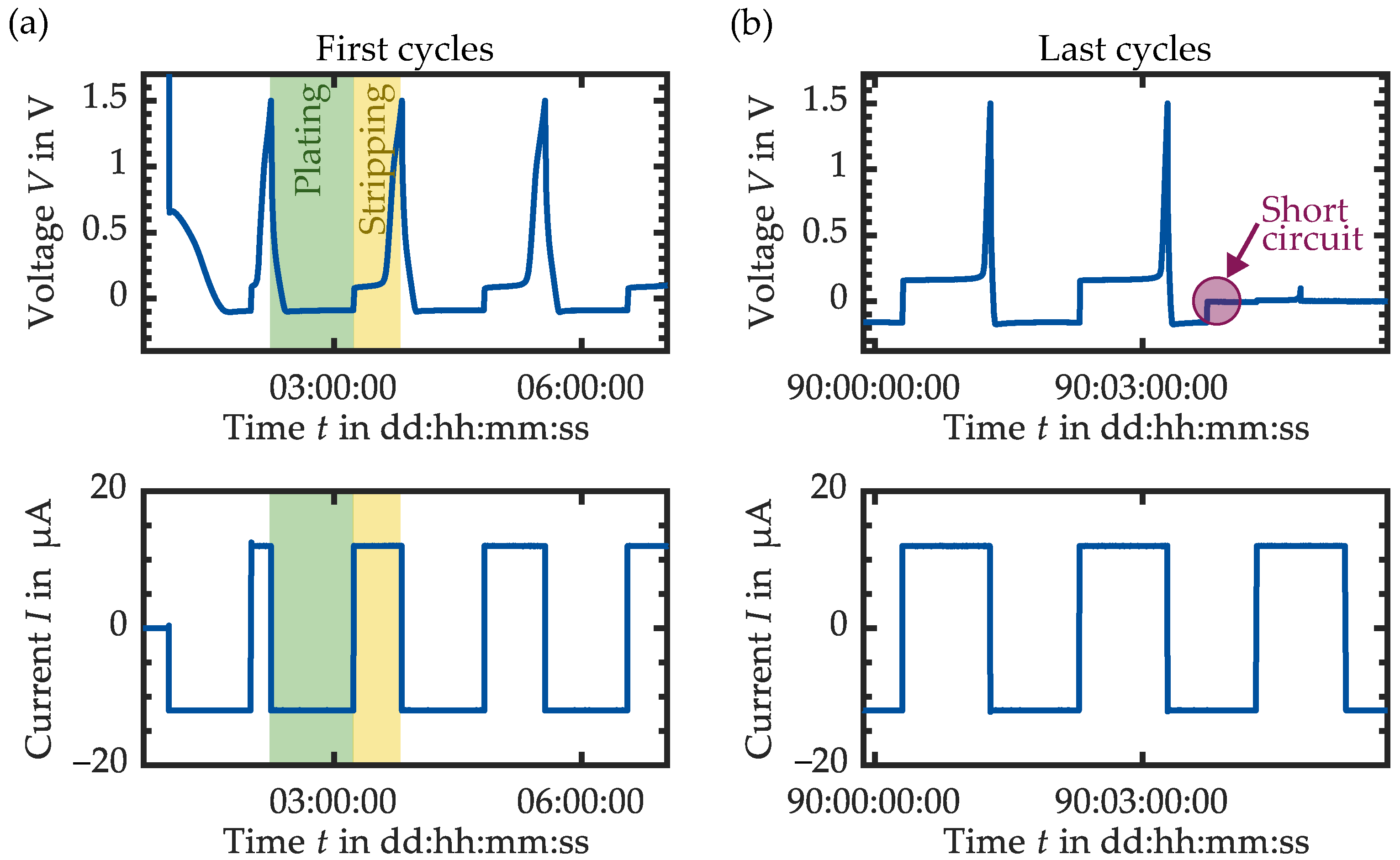
As a representative of all measurement series, the voltage curve during the cycling of the half-cell with stainless steel and carbon-coated current collector are examined in more detail. Figure 3 displays voltage V and current I plotted against time t for the SST current collector. The first cycles are shown in (a), the cycles before the failure of the cell are shown in (b). After the cell is assembled, the potential is about V = 2.6 V , corresponding to the theoretical cell voltage of lithium against steel (iron). In the first step, lithium is deposited on the stainless steel current collector, and the cell voltage drops towards V = 0 V . Once the lithium potential dominates over the stainless steel potential, a symmetrical half-cell with Li vs. Li is formed. The theoretical cell potential is then V theo = 0 V , with overvoltages to be measured while the current flows. In the lithiation step (highlighted in green in Figure 3a) a negative voltage of about V = 80 mV is measurable. After one hour and a converted charge quantity of Q plate = 12 μ Ah , the current direction is reversed. The Li is stripped from the SST current collector (highlighted in yellow) and deposited back onto the Li foil. At the beginning of this step, a voltage of V = + 80 mV is measurable.
Plating and stripping take place alternately until the cell fails. Figure 3b shows the last cycles before the cell voltage drops to V = 0 V , which indicates an internal cell short circuit due to dendrite formation. In addition, an increase in overvoltages can be seen compared to the first cycles in (a). The cell voltage during the plating and stripping process is now about V = ± 160 mV , indicating an increase in the cell’s internal resistance due to electrolyte decomposition.
Figure 4 displays an excerpt of voltage V and current I plotted against time t for the experiment with the carbon-coated aluminum current collector. Regarding the voltage curve of a plating process (highlighted in green) in Figure 4a, it can be observed that the voltage drops steadily from V = 1.5 V to V 0.15 V by applying a current of I = 12 μ A . However, the voltage remains above V > 0 V . It can be concluded that no Li plating takes place using this current collector material, but rather an intercalation of lithium ions in the carbon structure. The stripping or deintercalation process (highlighted in yellow) shows an almost linear increasing curve up to V = 1.5 V after the current direction is reversed. Comparing with [40], the voltage profile indicates soft carbon as the coating material.
In the following subsections, the results for the different cell setups are shown. First, the influence of the current collector material for in situ lithium deposition will be discussed. Subsequently, the impact of SIL in the electrolyte layer is investigated in the second subsection.

3.1. Variation of the Current Collector Material

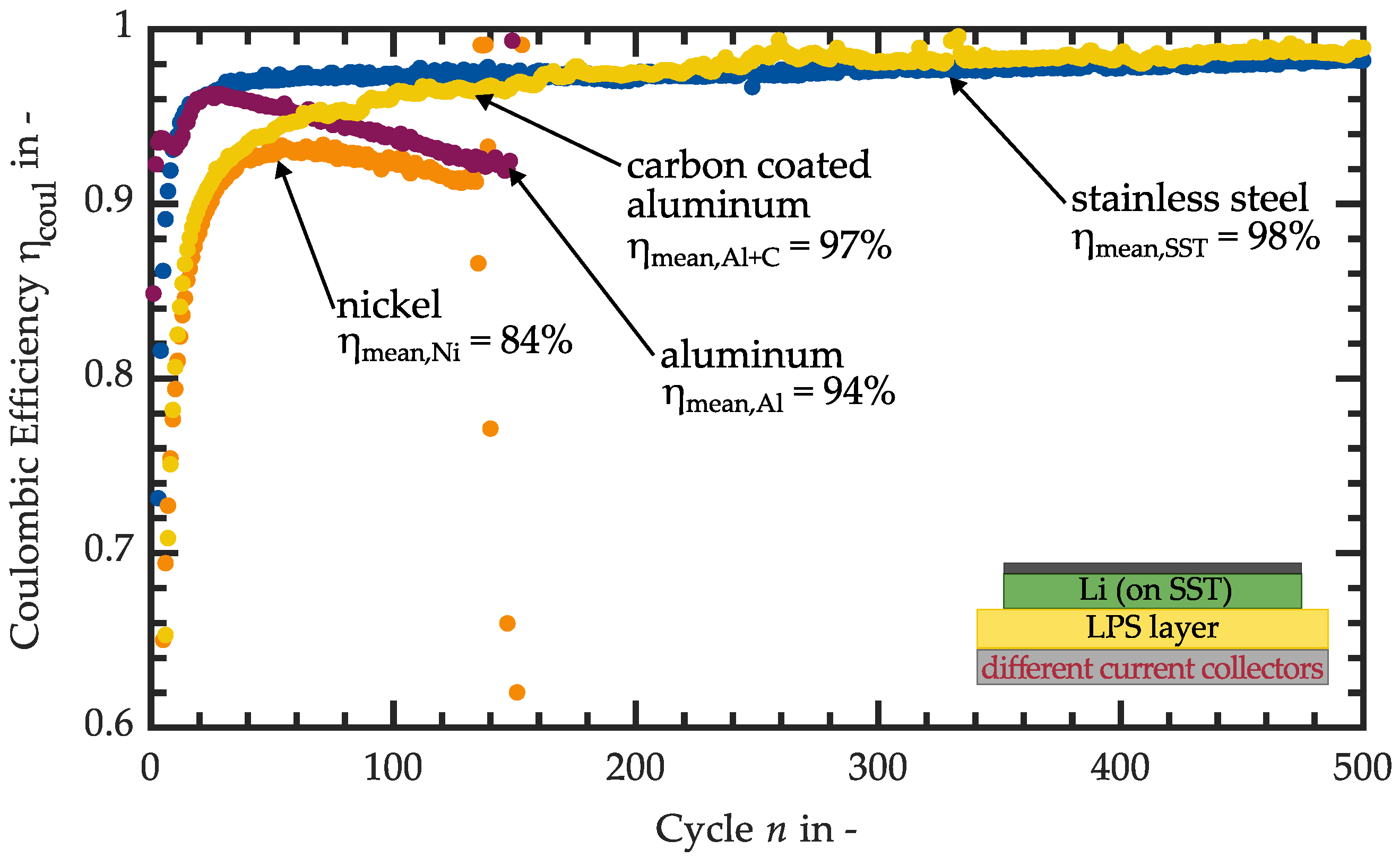
For comparing half-cells with different current collector materials, cells are set up according to Figure 2a with a slurry-based LPS electrolyte layer coated on various metal foils. The Coulombic efficiency η coul is considered first, Figure 5 shows the course of η coul plotted against the number of cycles n.
The efficiency of the half-cell setup with an SST current collector (shown in blue) rises to over η coul = 95 % within the first 15 cycles. In this case, it can be assumed that a part of the lithium is consumed in the first cycles for initial SEI formation and, thus, cannot be recovered in the stripping process. After the surface layer is established, the CE remains very stable at a slightly increasing level over several hundred cycles. This measurement results in an average efficiency of η mean , SST = 98 % . The cell shown here reaches a cycle number of n = 1095 (outside the display range of Figure 5) before the cell voltage shows a constant voltage of V = 0 V , indicating an internal cell short circuit.
Regarding the nickel current collector results (orange) the CE rises slower and reaches its maximum of η coul = 93.3 % at cycle n = 71 . After that, the curve drops, and after n = 136 cycles, a short circuit can be observed in the voltage curve of this cell. The average efficiency is η mean , Ni = 84 % .
The efficiency with the aluminum current collector (pink) initially follows a similar course to the test with the SST current collector. The efficiency increases to η coul = 96 % within n = 25 cycles but then drops very steeply. Here too, a short circuit is observed as a failure mechanism in the voltage curve. Over all cycles, the average efficiency is η mean , Al = 94 % .
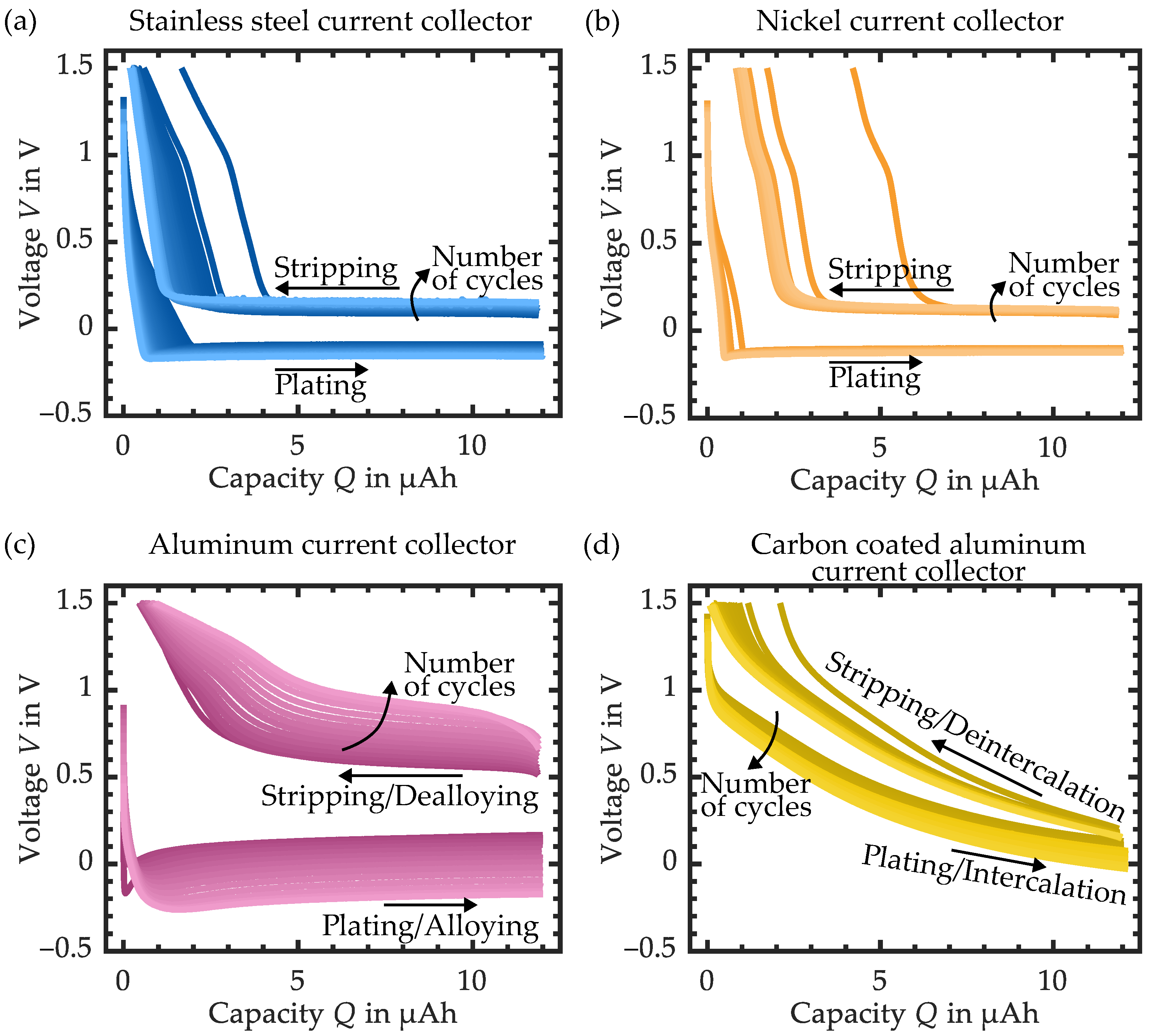
For the interpretation of the results, overvoltages of the different cell setups are considered in more detail in the next step. Figure 6 shows the voltage V plotted against the capacity Q for each cell setup, and the coloring becomes brighter with an increasing number of cycles. The following voltage values are always taken at the capacity of Q = 6 μ Ah .
Plating and stripping on/from the SST collector (Figure 6a) starts with a symmetric overpotential of V = ± 80 mV which rises to around V = ± 160 mV within n = 1095 cycles. This behavior indicates homogeneous lithium deposition, a stable SEI layer, and a low internal resistance increase over time, which is associated with low electrolyte decomposition.
The nickel current collector (Figure 6b) shows a slightly higher overvoltage of V = ± 101 mV that increases during n = 136 cycles to V = ± 134 mV . During the stripping process, it can be observed that the voltage rises in the direction of V = 1.5 V at around Q = 2 μ Ah , which corresponds to a transferred charge amount of Q strip = 10 μ Ah . This difference in the amount of charge between the plating and stripping steps results in the low CE of the nickel current collector. It indicates that in each cycle, a partial recreation of the SEI layer takes place and it is not stable. One possible explanation for this behavior is that SEI layer components react with the nickel current collector. It is conceivable that the Li2S and Li3P formed during cycling, in direct contact with nickel, may (partially) act as a conversion electrode additionally to the plating/stripping process under the formation of Ni3S2 or Ni3P, analogous to nickel sulfide and nickel phosphide electrodes [41,42]. Publications on the subject of nickel sulfide electrodes show that the reaction 2Li2S + 3Ni → 4Li + Ni3S2 only takes place at voltages around V 2 V , therefore, the formation of Ni3S2 is rather excluded in the present measurements [41,43,44]. Considering the voltage range for the formation of Ni3P below V 1.5 V , this reaction is more likely [42,45,46]. At the end of the plating process, Li3P is present as part of the SEI layer on the side of the nickel current collector and, thus, represents a fully lithiated conversion electrode. During the lithium stripping from the nickel foil, the Li3P is additionally delithiated according to the reaction Li3P + 3Ni → 3Li + Ni3P. In the following plating step, this reaction turns around. It is assumed that this “side reaction” and the associated reversible formation of Ni3P ↔ Ni causes the nickel current collector to decompose and become porous, which leads to loss of contact with the electrolyte layer.
Regarding the voltage curves of the aluminum current collector in Figure 6c, it can first be observed that the average potential is higher compared to the steel or nickel current collectors due to the potential of the Li-Al alloy of V LiAl = 0.3 V vs. Li/ Li + [47]. It can also be seen that the overvoltages are higher than V OV , LiAl , start > ± 100 mV with respect to the mean potential of V = 0.3 V and increase by up to V OV , LiAl , end = ± 400 mV as the number of cycles increases. The measurement results of this cell setup can be interpreted as follows: The high Coulombic efficiency of the first cycles (Figure 5—shown in pink) can be attributed to the reversible alloy formation between lithium and the aluminum current collector. However, this process does not seem to be permanently stable since the overvoltages rise significantly and the CE drops linearly after n = 25 cycles. This can be attributed to several effects. On the one hand, the repeated Li alloying–dealloying leads to volume changes, which result in a loss of contact with the electrolyte layer and a pulverization of the Al [48]. Furthermore, Rehnlund et al. [49] describes the alloy formation and the irreversible loss of lithium in aluminum particles in their publication. At the beginning of lithiation, lithium migrates from the particle boundary toward the particle center of the alloying metal. During the subsequent delithiation, it diffuses to the electrode surface, and further toward the center of the particle. This process leads to the fact that after several cycles, the lithium content in the center of the particle increases and less lithium can alloy. In terms of CE, this means that less Li can be recovered in the stripping process. In addition, it is suspected that SEI components interact with the aluminum besides the alloying–dealloying, as with the nickel current collector. So the formation of aluminum sulfide Al2S3 by the reaction of LiAl with Li2S is possible. Senoh et al. [50] note poor capacity retention for Al2S3 conversion electrodes. This observation coincides with the present measurement results. In summary, the progressive dissolution of the aluminum and the presumed decomposition of the SEI layer components lead to the increase in the internal cell resistance, which confirms the rapid growth of the overvoltages and the low CE.
The overvoltages of the carbon-coated Al current collector are considered next; see Figure 6d. It must be mentioned here that no information from the manufacturer about the type of carbon used for the coating is available. In the plating direction, the voltage curve starts to drop steadily from V 1 V , not falling below V = 0 V . During the stripping process, the voltage increases almost linearly from V 0.15 V to V = 1.5 V . Looking at the difference between the first and last cycle, an overvoltage increase of Δ V OV , Al + C = ± 130 mV can be observed. The voltage profile indicates the intercalation and deintercalation of the lithium in the carbon. One possible reason is that the intercalation causes the lithium to be non-metallic, preventing direct contact with the electrolyte layer and consequently, its progressive decomposition. The carbon-coating can also prevent direct contact between the aluminum and electrolyte layers or SEI components, so alloying and the presumed reaction to Al2S3 does not take place to the same extent as with an uncoated Al current collector.
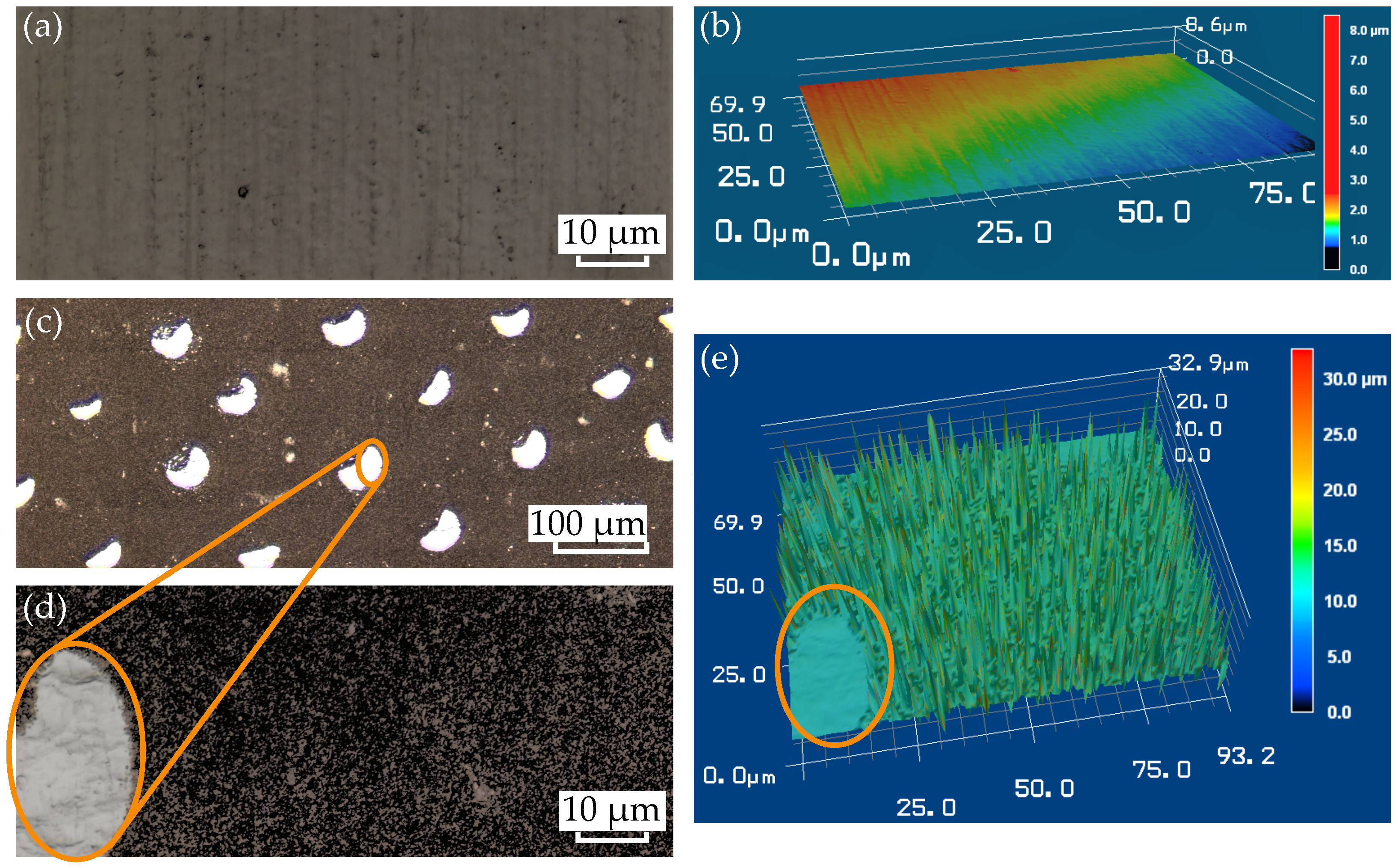
Stainless steel shows the best performance among all of the current collectors investigated here. It shows a stable course of the CE with an average efficiency of η mean , SST = 98 % , and the CE increases to a high value within a few cycles. Likewise, low overpotentials can be observed. The carbon-coated aluminum shows the second-best result. The highest values for Coulombic efficiency are achieved here, but the average value in CE is lower, since a stable course is only established after almost n = 250 cycles. In comparison to the result of the SST current collector, many more cycles are needed to finish the stabilization process of CE. One possible reason is identified in the rougher surface of the carbon structure compared to blank stainless steel. This results in a larger surface area that needs to be passivated by irreversible reactions and, therefore, might explain the reduced CE up to cycle number n = 200 . Figure 7 shows images of the current collector’s surface taken with a 3D laser scanning microscope. In the case of the SST current collector (see Figure 7a—magnification k x = 150 ), parallel grooves can be observed, which are presumably due to the production of the foil by a rolling process.
In Figure 7b, the height profile shows a almost smooth and flat surface. Looking at the carbon-coated aluminum foil (Figure 7c) at a magnification of k x = 20 , evenly distributed crescent-shaped white spots next to the dark carbon-coating can be identified. Taking a closer look at the brighter areas (Figure 7d—magnification k x = 150 ), marked in orange, it becomes clear that there is no carbon-coating on the aluminum. The height profile (Figure 7e) confirms this observation, as in this area the surface is almost flat. In the carbon-coated area, however, a strong structuring with distinct differences in height can be seen. The images confirm the assumption of a rougher, and thus larger, surface area of the carbon-coated current collector compared to the stainless steel. In addition, there is the possibility that the aluminum spots come into direct contact with the SSE layer, resulting in a partial alloying/dealloying during cycling. This could be another reason for the slow increase in CE at the beginning. During the first n = 250 cycles, intercalation and alloying take place at the same time, the aluminum spots decompose until they lose contact with the electrolyte layer. From this point on, only intercalation takes place and CE stabilizes.
In addition, it is observed that all cells fail due to a short circuit, which indicates dendrite formation [18]. Compared to half-cells with liquid electrolyte and limited electrolyte volume, the drying out of the cell and, thus, a very strong increase in the internal resistance as a failure criterion, is frequently observed here [51].

3.2. SIL in LPS Layer

Based on the results of the variation of the current collector material, the SST foil is selected for the tests with SIL. The aim is to investigate whether the CE can be further increased.
Figure 8 shows the course of the Coulombic efficiency of the cell setup with [Li(G3)]TFSI in the electrolyte layer compared to the setup without SIL. In addition, the voltage curves are shown in Figure 9 as a function of the number of cycles.
Looking at the CE in Figure 8, the cell setup with SIL in the LPS layer (shown in green) starts at a value of η coul = 60 % and increases to over η coul = 85 % within the first n = 19 cycles, after which the efficiency increases almost linearly up to cycle n = 128 . Up to this number of cycles, an average CE of η mean , Li ( G 3 ) = 85 % is achieved. The cell exhibits unstable behavior in the range from 129 < n < 149 , with the CE temporarily falling below η coul = 60 % (outside the display range). Subsequently, the CE increases until the cell fails with a short circuit after n = 169 cycles. If the cycles from n = 129 are included in the mean value calculation, this results in η mean , Li ( G 3 ) = 81 % .
In Figure 9, the voltage curves are plotted for the comparison of the overvoltages of the cells with and without [Li(G3)]TFSI in the solid electrolyte layer. On the left of the figure, analogous to Figure 6, the voltage V in green of every tenth cycle is plotted versus the amount of charge Q, with the darkest color shading representing the first cycle and the lightest color representing the last cycle. In addition, the tenth, as well as the 150th cycle of the cell with a pure LPS layer is inserted in blue for comparison. On the right side of the figure is an enlargement, which shows the 10th and the 150th cycle of the respective cell setups. At the beginning of the experiment with SIL, during the plating process, the voltage profile drops to a constant value of V = 36 mV within a charge amount of Q = 2 μ Ah . During stripping, the potential is initially about V 40 mV and increases steeply after a charge conversion of Q = 6 μ Ah . As the cyclization proceeds, the overvoltages grow to V = 58 mV and V = 64 mV (at Q = 6 μ Ah ), respectively.
Comparing this course with the setup without SIL in the LPS layer, two main differences can be seen: First, the overvoltages are significantly lower with SIL (Figure 9—right side), and second, the voltage increases later in the stripping process for the cell buildup without SIL (Figure 9—left side). The first observation regarding low overvoltages with [Li(G3)]TFSI shows that its addition can significantly reduce the cell’s internal resistance. The second observation coincides with the courses of the CE in Figure 8. One possible explanation could be that due to the presumed increase in the contact area between the electrolyte layer with [Li(G3)]TFSI and the current collector/lithium foil, more SEI must be formed, and consequently, more lithium is consumed. It should be mentioned that for all half-cells, not only the interface layer on the side of the current collector but also on the side of the lithium foil must be formed for a stable cyclization behavior. Nevertheless, comparing it to the current literature using SIL in a sulfide-based electrolyte layer [35,52,53], the present half-cell measurement is not consistent with the results in these publications. The explanation might be found by looking at the differences. First is the use of a lithium-indium (Li-In) counter electrode instead of a pure lithium metal electrode. Indium forms an alloy with lithium and shows a higher potential of about V LiIn = 0.6 V vs. Li/ Li + , which leads to a more stable behavior with reduced electrolyte decomposition [54]. Furthermore, other kinds of sulfide electrolytes are used. Particularly worth mentioning is lithium phosphorus sulfur chloride (LPSCl) with the chemical sum formula Li6PS5Cl. It is known for its wider electrochemical stability window vs. Li/ Li + and a higher ionic conductivity compared to LPS [55]. Another difference is the type of binder for the slurry-based processing of the electrolyte layer. In our experiments, we use HNBR, in comparison to other publications often using nitrile-butadiene rubber (NBR) [35] or no binder (dry pressing of electrolyte powder) [52,53]. All these differences might be reasons for the contradictory behavior of the presented measurement result.
With reference to the hypothesis stated at the beginning of this paper based on [35] (see Figure 1b), the measurements carried out do not confirm the assumption that the addition of an SIL improves the in situ lithium deposition with respect to CE. However, a reduction in the cell internal resistance can be confirmed.

3.3. Summary of the Results

The following subsection is intended to provide an overview of all of the results and to compare them qualitatively. For this purpose, Table 1 contrasts the measured half-cell setups regarding several aspects: mean Coulombic efficiency η mean , highest achieved Coulombic efficiency η max of a cycle, number of cycles before cell failure n max , lowest overvoltage V OV , start related to the mean potential, increase in overvoltage per cycle between the first and last cycle Δ V OV , n and a comment describing specific details of each experiment.
For comparison, the cell design with a stainless steel current collector and LPS layer shows the highest average Coulombic efficiency, the highest number of cycles achieved, as well as the lowest increase in overvoltages per cycle. Nickel and aluminum cannot reach these values. Especially in the case of aluminum, the extreme increase in overvoltages, by approximately ± 2 mV cycle , must be taken into account. Due to suspected distinct side reactions, both nickel- and aluminum-based current collectors cannot be recommended for further investigation. The cell setup with the carbon-coated current collector shows the highest Coulombic efficiency η max = 99.3 % , which is achieved in cycle n = 259. This behavior can be attributed to the intercalation/deintercalation mechanism. Inserting [Li(G3)]TFSI in the LPS layer combined with a stainless steel current collector cannot improve CE compared to using a pure LPS layer. However, the low overvoltage is remarkable here.
Stainless-steel- and carbon-coated aluminum showing high reversibility, however, are promising candidates and worth looking further into. In terms of achievable energy density on the cell level, stainless steel shows an advantage due to the lower anode potential resulting in a higher full-cell voltage. Furthermore, a combination of carbon-coating on a stainless steel current collector would be conceivable.

4. Conclusions

In this paper, various current collectors were investigated in half-cell setups with regard to their suitability for in situ lithium deposition in solid-state cells with an LPS electrolyte. The focus was on the use of metal foils as current collectors and a slurry-based solid electrolyte layer, since the transfer to known production techniques for lithium-ion cells is possible here. Among the investigated current collector materials, stainless steel shows the best result considering the Coulombic efficiency ( η mean , SST = 98 % ). In addition, the highest number of cycles and a low increase in overvoltages can be observed with this cell setup. A carbon-coated aluminum current collector achieves the second-highest CE. Pure aluminum, as well as nickel, are suspected to react with SEI components, resulting in a low achievable number of cycles and high overvoltages. In addition, an approach was tested in which the SIL [Li(G3)]TFSI was added to the solid electrolyte layer. Compared to the cell design without SIL, this showed a low CE but a significant reduction in overvoltages.

Author Contributions

Conceptualization, T.K.; methodology, T.K.; investigation, T.K.; writing—original draft preparation, T.K.; writing—review and editing, T.K., F.H., J.P.-B. and J.H.; visualization, T.K.; supervision, K.P.B.; funding acquisition, K.P.B. All authors have read and agreed to the published version of the manuscript.

Funding

The project on which this publication is based was funded by the Baden-Württemberg Ministry of Economics, Labor and Tourism under grant no. BW1_0094/05 as part of the invest BW funding program. The author is responsible for the content of this publication.

Data Availability Statement

Not applicable.

Acknowledgments

The authors thank Alexander Blasi for supporting the measurements with carbon-coated aluminum foil, as well as IoLiTec Ionic Liquids Technologies GmbH for providing materials.

Conflicts of Interest

The authors declare no conflict of interest. The funders had no role in the design of the study; in the collection, analyses, or interpretation of data; in the writing of the manuscript, or in the decision to publish the results.

Abbreviations

The following abbreviations are used in this manuscript:
AlAluminum
CECoulombic efficiency
CuCopper
HNBRHydrogenated nitrile-butadiene rubber
LiLithium
Li-InLithium-indium
Li + Lithium ion
[ Li ( G 3 ) ] TFSI Lithium triglyme bis(trifluoromethanesulfonyl)imide
LPSLithium phosphorus sulfide ( β -Li3PS4)
LPSClLithium phosphorus sulfur chloride (Li6PS5Cl)
NBRNitrile-butadiene rubber
NiNickel
SESolid electrolyte
SEsSolid electrolytes
SSESolid-state electrolyte
SEISolid electrolyte interface
SILSolvate ionic liquid
SSTStainless steel
vs.Versus

References

  1. Su, H.; Jiang, Z.; Liu, Y.; Li, J.; Gu, C.; Wang, X.; Xia, X.; Tu, J. Recent progress of sulfide electrolytes for all-solid-state lithium batteries. Energy Mater. 2022, 2, 200005. [Google Scholar] [CrossRef]
  2. Goodenough, J.B.; Kim, Y. Challenges for Rechargeable Li Batteries. Chem. Mater. 2010, 22, 587–603. [Google Scholar] [CrossRef]
  3. Chen, S.; Yang, X.; Zhang, J.; Ma, J.; Meng, Y.; Tao, K.; Li, F.; Geng, J. Aluminum–lithium alloy as a stable and reversible anode for lithium batteries. Electrochim. Acta 2021, 368, 137626. [Google Scholar] [CrossRef]
  4. Xu, X.Q.; Cheng, X.B.; Jiang, F.N.; Yang, S.J.; Ren, D.; Shi, P.; Hsu, H.; Yuan, H.; Huang, J.Q.; Ouyang, M.; et al. Dendrite—Accelerated thermal runaway mechanisms of lithium metal pouch batteries. SusMat 2022, 2, 435–444. [Google Scholar] [CrossRef]
  5. Deng, J.; Yang, X.; Zhang, G. Simulation study on internal short circuit of lithium ion battery caused by lithium dendrite. Mater. Today Commun. 2022, 31, 103570. [Google Scholar] [CrossRef]
  6. Xu, W.; Wang, J.; Ding, F.; Chen, X.; Nasybulin, E.; Zhang, Y.; Zhang, J.G. Lithium metal anodes for rechargeable batteries. Energy Environ. Sci. 2014, 7, 513–537. [Google Scholar] [CrossRef]
  7. Varzi, A.; Raccichini, R.; Passerini, S.; Scrosati, B. Challenges and prospects of the role of solid electrolytes in the revitalization of lithium metal batteries. J. Mater. Chem. A 2016, 4, 17251–17259. [Google Scholar] [CrossRef] [Green Version]
  8. Shen, Y.; Zhang, Y.; Han, S.; Wang, J.; Peng, Z.; Chen, L. Unlocking the Energy Capabilities of Lithium Metal Electrode with Solid-State Electrolytes. Joule 2018, 2, 1674–1689. [Google Scholar] [CrossRef] [Green Version]
  9. Lau, J.; DeBlock, R.H.; Butts, D.M.; Ashby, D.S.; Choi, C.S.; Dunn, B.S. Sulfide Solid Electrolytes for Lithium Battery Applications. Adv. Energy Mater. 2018, 8, 1800933. [Google Scholar] [CrossRef] [Green Version]
  10. Wu, J.; Liu, S.; Han, F.; Yao, X.; Wang, C. Lithium/Sulfide All-Solid-State Batteries using Sulfide Electrolytes. Adv. Mater. 2021, 33, e2000751. [Google Scholar] [CrossRef]
  11. Kim, K.J.; Balaish, M.; Wadaguchi, M.; Kong, L.; Rupp, J.L.M. Solid–State Li–Metal Batteries: Challenges and Horizons of Oxide and Sulfide Solid Electrolytes and Their Interfaces. Adv. Energy Mater. 2021, 11, 2002689. [Google Scholar] [CrossRef]
  12. Doerrer, C.; Capone, I.; Narayanan, S.; Liu, J.; Grovenor, C.R.M.; Pasta, M.; Grant, P.S. High Energy Density Single-Crystal NMC/Li6PS5Cl Cathodes for All-Solid-State Lithium-Metal Batteries. ACS Appl. Mater. Interfaces 2021, 13, 37809–37815. [Google Scholar] [CrossRef]
  13. Zhang, Q.; Cao, D.; Ma, Y.; Natan, A.; Aurora, P.; Zhu, H. Sulfide-Based Solid-State Electrolytes: Synthesis, Stability, and Potential for All-Solid-State Batteries. Adv. Mater. 2019, 31, e1901131. [Google Scholar] [CrossRef]
  14. Suci, W.G.; Aliwarga, H.K.; Azinuddin, Y.R.; Setyawati, R.B.; Stulasti, K.N.R.; Purwanto, A. Review of various sulfide electrolyte types for solid-state lithium-ion batteries. Open Eng. 2022, 12, 409–423. [Google Scholar] [CrossRef]
  15. Oh, P.; Yun, J.; Choi, J.H.; Saqib, K.S.; Embleton, T.J.; Park, S.; Lee, C.; Ali, J.; Ko, K.; Cho, J. Development of High-Energy Anodes for All-Solid-State Lithium Batteries Based on Sulfide Electrolytes. Angew. Chem. (Int. Ed. Engl.) 2022, 61, e202201249. [Google Scholar] [CrossRef]
  16. Wang, Q.; Liu, B.; Shen, Y.; Wu, J.; Zhao, Z.; Zhong, C.; Hu, W. Confronting the Challenges in Lithium Anodes for Lithium Metal Batteries. Adv. Sci. 2021, 8, e2101111. [Google Scholar] [CrossRef] [PubMed]
  17. Wang, S.; Fang, R.; Li, Y.; Liu, Y.; Xin, C.; Richter, F.H.; Nan, C.W. Interfacial challenges for all-solid-state batteries based on sulfide solid electrolytes. J. Mater. 2021, 7, 209–218. [Google Scholar] [CrossRef]
  18. Otoyama, M.; Suyama, M.; Hotehama, C.; Kowada, H.; Takeda, Y.; Ito, K.; Sakuda, A.; Tatsumisago, M.; Hayashi, A. Visualization and Control of Chemically Induced Crack Formation in All-Solid-State Lithium-Metal Batteries with Sulfide Electrolyte. ACS Appl. Mater. Interfaces 2021, 13, 5000–5007. [Google Scholar] [CrossRef]
  19. Jiang, W.; Yan, L.; Zeng, X.; Meng, X.; Huang, R.; Zhu, X.; Ling, M.; Liang, C. Adhesive Sulfide Solid Electrolyte Interface for Lithium Metal Batteries. ACS Appl. Mater. Interfaces 2020, 12, 54876–54883. [Google Scholar] [CrossRef] [PubMed]
  20. Ke, X.; Wang, Y.; Dai, L.; Yuan, C. Cell failures of all-solid-state lithium metal batteries with inorganic solid electrolytes: Lithium dendrites. Energy Storage Mater. 2020, 33, 309–328. [Google Scholar] [CrossRef]
  21. Singer, C.; Schnell, J.; Reinhart, G. Scalable Processing Routes for the Production of All–Solid–State Batteries—Modeling Interdependencies of Product and Process. Energy Technol. 2021, 9, 2000665. [Google Scholar] [CrossRef]
  22. Wang, M.J.; Carmona, E.; Gupta, A.; Albertus, P.; Sakamoto, J. Enabling lithium-free manufacturing of pure lithium metal solid-state batteries through in situ plating. Nat. Commun. 2020, 11, 5201. [Google Scholar] [CrossRef] [PubMed]
  23. Qian, J.; Adams, B.D.; Zheng, J.; Xu, W.; Henderson, W.A.; Wang, J.; Bowden, M.E.; Xu, S.; Hu, J.; Zhang, J.G. Anode-Free Rechargeable Lithium Metal Batteries. Adv. Funct. Mater. 2016, 26, 7094–7102. [Google Scholar] [CrossRef]
  24. Heubner, C.; Maletti, S.; Auer, H.; Hüttl, J.; Voigt, K.; Lohrberg, O.; Nikolowski, K.; Partsch, M.; Michaelis, A. From Lithium–Metal toward Anode–Free Solid–State Batteries: Current Developments, Issues, and Challenges. Adv. Funct. Mater. 2021, 31, 2106608. [Google Scholar] [CrossRef]
  25. Homann, G.; Meister, P.; Stolz, L.; Brinkmann, J.P.; Kulisch, J.; Adermann, T.; Winter, M.; Kasnatscheew, J. High-Voltage All-Solid-State Lithium Battery with Sulfide-Based Electrolyte: Challenges for the Construction of a Bipolar Multicell Stack and How to Overcome Them. ACS Appl. Energy Mater. 2020, 3, 3162–3168. [Google Scholar] [CrossRef]
  26. Zhu, P.; Gastol, D.; Marshall, J.; Sommerville, R.; Goodship, V.; Kendrick, E. A review of current collectors for lithium-ion batteries. J. Power Source 2021, 485, 229321. [Google Scholar] [CrossRef]
  27. Shinzo, S.; Higuchi, E.; Chiku, M.; Hayashi, A.; Inoue, H. High-Rate Lithium Metal Plating and Stripping on Solid Electrolytes Using a Porous Current Collector with a High Aperture Ratio. ACS Appl. Energy Mater. 2021, 4, 12613–12622. [Google Scholar] [CrossRef]
  28. Shinzo, S.; Higuchi, E.; Chiku, M.; Hayashi, A.; Inoue, H. Suppression of Dendritic Growth on Li Negative Electrode for All-Solid-State Rechargeable Battery. ECS Meet. Abstr. 2020, MA2020-02, 980. [Google Scholar] [CrossRef]
  29. Chen, Y.; Kang, Y.; Zhao, Y.; Wang, L.; Liu, J.; Li, Y.; Liang, Z.; He, X.; Li, X.; Tavajohi, N.; et al. A review of lithium-ion battery safety concerns: The issues, strategies, and testing standards. J. Energy Chem. 2021, 59, 83–99. [Google Scholar] [CrossRef]
  30. Pan, H.; Zhang, M.; Cheng, Z.; Jiang, H.; Yang, J.; Wang, P.; He, P.; Zhou, H. Carbon-free and binder-free Li-Al alloy anode enabling an all-solid-state Li-S battery with high energy and stability. Sci. Adv. 2022, 8, eabn4372. [Google Scholar] [CrossRef]
  31. Wang, R.; Li, W.; Liu, L.; Qian, Y.; Liu, F.; Chen, M.; Guo, Y.; Liu, L. Carbon black/graphene-modified aluminum foil cathode current collectors for lithium ion batteries with enhanced electrochemical performances. J. Electroanal. Chem. 2019, 833, 63–69. [Google Scholar] [CrossRef]
  32. Yang, W.; Huang, R.; Ni, Z.; Cheng, H.; Zhou, S.; Wang, Y.; Li, X.; Zhang, Y.; Zhang, Y. Application and research of current collector for lithium-sulfur battery. Ionics 2022, 28, 1713–1738. [Google Scholar] [CrossRef]
  33. Chen, J.; Xu, X.; He, Q.; Ma, Y. Advanced Current Collectors for Alkali Metal Anodes. Chem. Res. Chin. Univ. 2020, 36, 386–401. [Google Scholar] [CrossRef]
  34. Ates, T.; Keller, M.; Kulisch, J.; Adermann, T.; Passerini, S. Development of an all-solid-state lithium battery by slurry-coating procedures using a sulfidic electrolyte. Energy Storage Mater. 2019, 17, 204–210. [Google Scholar] [CrossRef]
  35. Oh, D.Y.; Nam, Y.J.; Park, K.H.; Jung, S.H.; Kim, K.T.; Ha, A.R.; Jung, Y.S. Slurry–Fabricable Li + –Conductive Polymeric Binders for Practical All–Solid–State Lithium–Ion Batteries Enabled by Solvate Ionic Liquids. Adv. Energy Mater. 2019, 9, 1802927. [Google Scholar] [CrossRef]
  36. Fan, X.; Ji, X.; Han, F.; Yue, J.; Chen, J.; Chen, L.; Deng, T.; Jiang, J.; Wang, C. Fluorinated solid electrolyte interphase enables highly reversible solid-state Li metal battery. Sci. Adv. 2018, 4, eaau9245. [Google Scholar] [CrossRef] [Green Version]
  37. Zhu, Y.; He, X.; Mo, Y. Origin of Outstanding Stability in the Lithium Solid Electrolyte Materials: Insights from Thermodynamic Analyses Based on First-Principles Calculations. ACS Appl. Mater. Interfaces 2015, 7, 23685–23693. [Google Scholar] [CrossRef]
  38. Jabbari, V.; Yurkiv, V.; Rasul, M.G.; Phakatkar, A.H.; Mashayek, F.; Shahbazian-Yassar, R. In situ formation of stable solid electrolyte interphase with high ionic conductivity for long lifespan all-solid-state lithium metal batteries. Energy Storage Mater. 2023, 57, 1–13. [Google Scholar] [CrossRef]
  39. Byeon, Y.W.; Kim, H. Review on Interface and Interphase Issues in Sulfide Solid-State Electrolytes for All-Solid-State Li-Metal Batteries. Electrochem 2021, 2, 30. [Google Scholar] [CrossRef]
  40. Loeffler, B.N.; Bresser, D.; Passerini, S.; Copley, M. Secondary Lithium-Ion Battery Anodes: From First Commercial Batteries to Recent Research Activities. Johns. Matthey Technol. Rev. 2015, 59, 34–44. [Google Scholar] [CrossRef]
  41. Ni, S.; Yang, X.; Li, T. Fabrication of porous Ni3S2/Ni nanostructured electrode and its application in lithium ion battery. Mater. Chem. Phys. 2012, 132, 1103–1107. [Google Scholar] [CrossRef]
  42. Xiang, J.Y.; Wang, X.L.; Xia, X.H.; Zhong, J.; Tu, J.P. Fabrication of highly ordered porous nickel phosphide film and its electrochemical performances toward lithium storage. J. Alloys Compd. 2011, 509, 157–160. [Google Scholar] [CrossRef]
  43. WANG, J.; CHOU, S.; CHEW, S.; SUN, J.; FORSYTH, M.; MACFARLANE, D.; LIU, H. Nickel sulfide cathode in combination with an ionic liquid-based electrolyte for rechargeable lithium batteries. Solid State Ionics 2008, 179, 2379–2382. [Google Scholar] [CrossRef]
  44. Lee, Y.J.; Reddy, B.S.; Hong, H.A.; Kim, K.W.; Cho, S.J.; Ahn, H.J.; Ahn, J.H.; Cho, K.K. Synthesis and electrochemical properties of nickel sulfide/carbon composite as anode material for lithium–ion and sodium–ion batteries. Int. J. Energy Res. 2022, 46, 16883–16895. [Google Scholar] [CrossRef]
  45. Xiang, J.Y.; Tu, J.P.; Wang, X.L.; Huang, X.H.; Yuan, Y.F.; Xia, X.H.; Zeng, Z.Y. Electrochemical performances of nanostructured Ni3P–Ni films electrodeposited on nickel foam substrate. J. Power Source 2008, 185, 519–525. [Google Scholar] [CrossRef]
  46. Hayashi, A.; Inoue, A.; Tatsumisago, M. Electrochemical performance of NiP2 negative electrodes in all-solid-state lithium secondary batteries. J. Power Source 2009, 189, 669–671. [Google Scholar] [CrossRef]
  47. Bang, H.J.; Kim, S.; Prakash, J. Electrochemical investigations of lithium-aluminum alloy anode in Li/polymer cells. J. Power Source 2001, 92, 45–49. [Google Scholar] [CrossRef]
  48. Kwon, G.D.; Moyen, E.; Lee, Y.J.; Joe, J.; Pribat, D. Graphene-Coated Aluminum Thin Film Anodes for Lithium-Ion Batteries. ACS Appl. Mater. Interfaces 2018, 10, 29486–29495. [Google Scholar] [CrossRef]
  49. Rehnlund, D.; Lindgren, F.; Böhme, S.; Nordh, T.; Zou, Y.; Pettersson, J.; Bexell, U.; Boman, M.; Edström, K.; Nyholm, L. Lithium trapping in alloy forming electrodes and current collectors for lithium based batteries. Energy Environ. Sci. 2017, 10, 1350–1357. [Google Scholar] [CrossRef] [Green Version]
  50. Senoh, H.; Takeuchi, T.; Kageyama, H.; Sakaebe, H.; Yao, M.; Nakanishi, K.; Ohta, T.; Sakai, T.; Yasuda, K. Electrochemical characteristics of aluminum sulfide for use in lithium secondary batteries. J. Power Source 2010, 195, 8327–8330. [Google Scholar] [CrossRef]
  51. Heim, F.; Kreher, T.; Birke, K.P. The Influence of Micro-Structured Anode Current Collectors in Combination with Highly Concentrated Electrolyte on the Coulombic Efficiency of In-Situ Deposited Li-Metal Electrodes with Different Counter Electrodes. Batteries 2020, 6, 20. [Google Scholar] [CrossRef] [Green Version]
  52. Oh, D.Y.; Nam, Y.J.; Park, K.H.; Jung, S.H.; Cho, S.J.; Kim, Y.K.; Lee, Y.G.; Lee, S.Y.; Jung, Y.S. Excellent Compatibility of Solvate Ionic Liquids with Sulfide Solid Electrolytes: Toward Favorable Ionic Contacts in Bulk-Type All-Solid-State Lithium-Ion Batteries. Adv. Energy Mater. 2015, 5, 1500865. [Google Scholar] [CrossRef]
  53. Shin, M.; Gewirth, A.A. Incorporating Solvate and Solid Electrolytes for All–Solid–State Li 2 S Batteries with High Capacity and Long Cycle Life. Adv. Energy Mater. 2019, 9, 1900938. [Google Scholar] [CrossRef]
  54. Santhosha, A.L.; Medenbach, L.; Buchheim, J.R.; Adelhelm, P. The Indium–Lithium Electrode in Solid–State Lithium–Ion Batteries: Phase Formation, Redox Potentials, and Interface Stability. Batter. Supercaps 2019, 2, 524–529. [Google Scholar] [CrossRef]
  55. Reddy, M.V.; Julien, C.M.; Mauger, A.; Zaghib, K. Sulfide and Oxide Inorganic Solid Electrolytes for All-Solid-State Li Batteries: A Review. Nanomaterials 2020, 10, 1606. [Google Scholar] [CrossRef]
Figure 1. Schematic illustration for improving in situ lithium deposition by using an SIL: (a) Lithium deposition on a current collector in combination with a binder-containing solid electrolyte layer. The binder encloses the electrolyte particles; there are only a few ionic conductive paths. This results in inhomogeneous lithium deposition. (b) By swelling the binder with SILs, many Li + -conducting paths are formed and the lithium is deposited uniformly on the current collector. Adapted from [35].
Batteries 09 00412 g001
Figure 2. Illustration of the two different cell setups: (a) Half-cell setup for test with variation of current collectors for Li deposition. (b) Half-cell setup for test with SIL in SE layer.
Batteries 09 00412 g002
Figure 3. Plot of voltage V and current I over time t of the half-cell with stainless steel current collector for in situ lithium deposition. (a) Shows the voltage and current curve of the first cycles, with an example of a plating process highlighted in green and a stripping process highlighted in yellow. In (b), the last plating/stripping cycle can be seen, as well as the voltage drop to V = 0 V , which indicates an internal cell short circuit.
Batteries 09 00412 g003
Figure 4. Excerpt of voltage V and current I over time t of the half-cell with the carbon-coated current collector for in situ lithium deposition. (a) Shows the voltage curve with an example of an intercalation process highlighted in green and a deintercalation process highlighted in yellow. It can be observed that the voltage remains above V > 0 V for this current collector, suggesting that no lithium plating is taking place. In (b), the related current profile is plotted.
Batteries 09 00412 g004
Figure 5. Coulombic efficiency η coul plotted against the number of cycles n for half-cells with different current collector materials. The stainless steel current collector (blue) shows a stable course with an average efficiency of η mean , SST = 98 % . Using a nickel current collector (orange) results in a low average CE of η mean , Ni = 84 % . The aluminum current collector (pink) starts with a high CE increasing to a maximum of η coul = 96 % , followed by a steep decrease. The half-cell with the carbon-coated current collector (yellow) shows a slow increase in CE from the first cycle on. After 250 cycles, a stable course at around η coul = 98.5 % can be observed.
Batteries 09 00412 g005
Figure 6. Plot of the voltage curves of every 10th cycle versus capacity Q for the different half-cell setups. The darkest color shading represents the first cycle, the lightest color shading represents the last cycle. (a) Setup with stainless steel current collector for in situ deposition. (b) Setup with nickel current collector. (c) Setup with aluminum current collector. (d) Setup with carbon-coated aluminum current collector.
Batteries 09 00412 g006
Figure 7. Images of the current collector’s surface taken with a laser scanning microscope. (a) Shows the surface of the SST current collector at a magnification of k x = 150 , and (b) is the corresponding height profile of the surface unevenness. (c) Shows the carbon-coated aluminum foil at a magnification of k x = 20 and (c) at a magnification of k x = 150 , and (e) is the corresponding height profile of the surface unevenness. The orange circles in (ce) mark the same uncoated area.
Batteries 09 00412 g007
Figure 8. Coulombic efficiency η coul plotted against the number of cycles n for half-cells with and without SIL in the LPS layer using a stainless steel current collector. The cell setup without SIL (blue) shows a stable course with an average efficiency of η mean , SUS = 98 % . Using [Li(G3)]TFSI in the LPS layer (green) results in a slowly rising CE with an average of η mean , Li ( G 3 ) = 85 % until cycle n = 129 .
Batteries 09 00412 g008
Figure 9. Plot of the voltage curves V in V of every 10th cycle versus capacitance Q in µAh for the comparison of the half-cell setups with and without [Li(G3)]TFSI in the LPS layer. The darkest color shading represents the first cycle, the lightest color shading represents the last cycle. On the left side, the result for the cell with [Li(G3)]TFSI is shown in green. In addition, the tenth, as well as the 150th cycle of the cell with a pure LPS layer is inserted in blue for comparison. On the right side of the figure is an enlargement, which also shows the 10th and the 150th cycle of the respective cell setups.
Batteries 09 00412 g009
Table 1. Overview of the results of the different half-cell setups.
Cell Setup
Current Collector
SE Layer
η mean η max n max V OV , start
@ Q = 6 μ Ah
Δ V OV , n
@ Q = 6 μ Ah
Comment
Stainless steel
LPS
98%98.8%
@ n = 1045
1095 ± 80 mV ± 0.073 mV cycle No alloy forming with Li or reaction
with SEI components
Nickel
LPS
84%93.3%
@ n = 71
136 ± 101 mV ± 0.242 mV cycle No alloy forming with Li, suspected reaction
of SEI components with the nickel current
collector and decomposition of the latter
Aluminum
LPS
94%95%
@ n = 25
149 ± 100 mV ± 2.013 mV cycle Alloy forming with Li, suspected reaction of
SEI components with the Al current collector
decomposition of the latter
Carbon-coated aluminum
LPS
97%99.3%
@ n = 259
725 ± 110 mV ± 0.179 mV cycle Intercalation observed
Stainless steel
LPS + 3.5 wt . % [Li(G3)]TFSI
85%94.8%
@ n = 169
169 ± 36 mV ± 0.166 mV cycle No alloy forming with Li, slow formation of
SEI suspected
Disclaimer/Publisher’s Note: The statements, opinions and data contained in all publications are solely those of the individual author(s) and contributor(s) and not of MDPI and/or the editor(s). MDPI and/or the editor(s) disclaim responsibility for any injury to people or property resulting from any ideas, methods, instructions or products referred to in the content.