Article

Proof of Concept: The GREENcell—A Lithium Cell with a F-, Ni- and Co-Free Cathode and Stabilized In-Situ LiAl Alloy Anode

1
Fraunhofer Institute for Manufacturing Engineering and Automation IPA, Nobel Str. 12, 70569 Stuttgart, Germany
2
Electrical Energy Storage Systems, Institute for Photovoltaics, University of Stuttgart, Pfaffenwaldring 47, 70569 Stuttgart, Germany
*
Author to whom correspondence should be addressed.
Batteries 2023, 9(9), 453; https://doi.org/10.3390/batteries9090453
Submission received: 11 July 2023 / Revised: 20 August 2023 / Accepted: 30 August 2023 / Published: 4 September 2023

Abstract

:
Given the rising upscaling trend in lithium-ion battery (LiB) production, there is a growing emphasis on the environmental and economic impacts alongside the high energy density demands. The cost and environmental impact of battery production primarily arise from the critical elements Ni, Co, and F. This drives the exploration of Ni-free and Co-free cathode alternatives such as LiMn2O4 (LMO) and LiFePO4 (LFP). However, the absence of Ni and Co results in reduced capacity and insufficient cyclic stability, particularly in the case of LMO due to Mn dissolution. To compensate for both low cathode capacitance and low cycle stability, we propose the GREENcell, a lithium cell combining a F-free polyisobutene (PIB) binder-based LMO cathode with a stabilized in -situ LiAL alloy anode. A LiAl alloy anode with the chemical composition of LiAl already shows a theoretical capacity of 993 Ah·kg−1. Therefore, it promises extraordinarily higher energy densities compared to a commercial graphite anode with a capacity of 372 Ah·kg−1. Following an iterative development process, different optimization strategies, especially those targeting the stability of the Al-based anode, were evaluated. During Al foil selection, foil purity and thickness could be identified as two of the dominant influencing parameters. A pressed-in stainless steel mesh provides both mechanical stability to the anode and facilitates alloy formation by breaking up the Al oxide layer beforehand. Additionally, a binder-stabilized Al oxide or silicate layer is pre-coated on the Al surface, posing as a SEI-precursor and ensuring a uniform liquid electrolyte distribution at the phase boundary. Employing a commercially available Si-containing Al alloy mitigated the mechanical degradation of the anode, yielding a favorable impact on long-term stability. The applicability of the novel optimized GREENcell is demonstrated using laboratory coin cells with LMO and LFP as the cathode. As a result, the functionality of the GREENcell was demonstrated for the first time, and thanks to the anode stabilization strategies, a capacity retention of >70% after 200 was achieved, representing an increase of 32.6% compared to the initial Al foil.

1. Introduction

By 2030, 20% of road vehicles will be powered by electrical energy [1]. The lithium-ion battery (LiB) holds a prominent position in the market for electrochemical energy storage. This is due to the advantageous characteristics of lithium, such as its low density (0.534 g·cm−3), the fast ion transport of the small lithium ions (0.76 Å), and the low reduction potential (−3.04 V vs. standard hydrogen electrode), which allow high gravimetric and volumetric energy densities [1]. There is a growing focus on not only meeting the high energy density demands but also considering the environmental and economic implications. The dominant environmental challenges of LiB technology include cost- and energy-intensive material production and processing (graphite and metal oxides) and the use of fluorine-containing and toxic components (electrolyte, metal oxide, and cathode binder) [1,2]. More than a third of the total price of a battery and 17.02% percent of CO2 emissions are attributable to the production of the cathode material [2,3]. The dominant cathode active material of commercial LiBs is lithium nickel manganese oxide (NMC, LiNixMnyCo1−x−yO2) and is composed of the elements lithium (Li), nickel (Ni), manganese (Mn), and cobalt (Co). Exemplary representatives are the low-Ni NMC111 (LiNi0.33Mn0.33Co0.33O2, 160 Ah·kg−1) and the high-Ni NMC811 (LiNi0.8Mn0.1Co0.1O2, 200 Ah·kg−1) [1]. Due to the shortage of less abundant elements and their occurrence limitation to only a few areas on earth, the elements Ni and Co have a critical character. The critical character is further reinforced by the classification of Ni and Co as carcinogenic, mutagenic, and toxic to reproduction (CMR) [4]. The ethically questionable mining conditions in the main deposit area of the Democratic Republic of the Congo (DRC), and the uncertain supply situation, give Co the position of the main cost bearer in battery production [1,2]. To overcome these environmental and economic challenges, Co- and Ni-free cathode active materials such as lithium iron phosphate (LiFePO4, LFP) and lithium manganese oxide (LiMn2O4, LMO) are used. The specific capacity of LFP (170 Ah·kg−1) and LMO (110 Ah·kg−1) is significantly lower than NMC, mainly due to the absence of Ni [5]. However, despite this difference, the price per kWh remains lower for LMO (LMO: 76.4 $·kWh−1) and LFP (LFP: 84.8 $·kWh−1) compared to NMC (NMC111: 88.4 $·kWh−1) [1]. This can be attributed to the significantly reduced material costs associated with LMO and LFP. Using a commercial graphite anode (Gr, 372 Ah·kg−1) results in gravimetric energy densities of ~216 Wh·kg−1 for the Gr||LMO cell system and ~211 Wh·kg−1 for Gr||LFP (compared to Gr||NMC811: 279 Wh·kg−1) [6].
Hence, to fulfill the high energy density demands, ongoing research is exploring alternative high-capacity anode materials. Li metal (3860 Ah·kg−1) has a 10 times higher specific capacity than the commercial anode material Gr. However, practical implementation is complicated due to inhomogeneous dendrite growth and an unstable anode/electrolyte interface. One way to overcome these issues is using a lithium aluminum (LiAl) alloy anode. LiAl alloy with the chemical composition of LiAl already shows a theoretical capacity of 993 Ah·kg−1 and therefore promises still extraordinarily higher energy densities than a Gr anode [7,8]. Compared to Li metal, the LiAl alloy has only a slightly increased potential (~0.3 V vs. Li+/Li), which has a minor effect on energy density [9]. Furthermore, incorporating the alloy anode not only leads to performance enhancement but also positively impacts production costs. An in-situ LiAl alloy formation process allows for the use of commercial Al foil (Al, 2.2 $ kg−1 (2023)) as the base component of the negative composite anode and minimizes the amount of inactive Li compared to a prelithiated Al foil [10]. The cost-intensive copper (Cu, 8.6 $ kg−1 (2023)) current collector and Gr anode (artificial Gr: 11 $ kg−1 (2020)) are thus eliminated [6,11]. Cost reduction and easier anode handling are the consequences that significantly optimize production conditions.
The commercialization of a Gr-based LiB with a cathode comprising LMO has not yet been achieved, primarily due to the accelerated degradation of the anode. Mn is dissolved from the spinel LMO cathode structure as Mn2+ by the hydrofluoric acid (HF) of the liquid electrolyte and migrates to the Gr anode, where it is reduced to Mn and clogs the intercalation planes of the Gr [12]. By replacing the intercalation process of the anode with an alloy formation process, the Mn dissolution problem can be circumvented, allowing the stable use of an LMO cathode.
Unfortunately, LiAl-based anodes have poor cycling stability and high overpotentials, especially during formation, called formation losses. Responsible are the volume changes of up to 95% that occur during the lithiation and delithiation of Al [7]. The mechanical stresses lead to irreversible structural changes, electrically isolated areas, and Al pulverization resulting in capacity loss [10]. The Al2O3 passivation layer on the aluminum (Al) surface leads to high formation losses during the initial charge cycle. These losses primarily result from the formation of poorly ionically conducting reaction products, specifically Li-Al-O, during the chemical breakdown of the Al2O3 layer by the incoming Li+ ions [7]. The high nucleation overvoltage of the LiAl formation process (−28.9 kJ·mol−1) further enhances the capacity loss during LiAl alloy formation due to the slowing down of the Li+ diffusion kinetics [7].
Various direct and indirect measures can be taken to stabilize LiAl anode technology artificially. Zheng et al. [13] proposed an indirect stabilization concept by cycling the LiAl phase within its Li solubility range to form a more stable monolithic anode. Following up on this, Zheng et al. [10,13] introduced the concept of “Degree of Al Utilization” (DAU), which indicates that a shallower lithiation depth leads to a longer cycle life for an Al foil. Chen et al. [14] reached an equivalent conclusion by showing the relationship between cycle life and the extent of reaction per cycle. In the literature, mechanical, chemical (e.g., surface coating), and electrolyte modifications are among the direct stabilization measures discussed [7,9]. In the field of mechanical pretreatment, notable studies by Min et al. [15] and Li et al. [16] have investigated the application of a three-dimensional mesh as a current collector, effectively achieving a three-dimensional current density distribution. The three-dimensional current density distribution has proven effective in reducing local currents and, as a result, mitigating overvoltages. Ling et al. [17] and Jiang et al. [18] use a chemical pretreatment in the form of a composite coating of poly(furfuryl alcohol)/carbon black binder and a phosphate conversion coating, respectively, to increase the solid electrolyte interface (SEI) stability and wettability of the Al foil. The positive influence of Al2O3 nanoparticle coating on the ionic conductivity at the electrode interface was shown by Salehan et al. [19]. In terms of the deliberate use of foreign elements in a pre-lithiated Al foil, such as silicon (Si) and Mn, Fan et al. [20] and Chen et al. [8] were able to increase the anode stability significantly due to superior electrochemical lithium ductility They achieved a cycle number of over 90, or even 1000 cycles, with a capacity retention of 80%, by utilizing LFP as the cathode material. Morita et al. [21] and Choi et al. [22] demonstrated the stabilizing effect of F-rich SEI on alloy anodes. Using an electrolyte modification with 3 wt% fluoroethylene carbonate (FEC), Choi et al. [22] realized a stable LiF-rich SEI, which increased the cycling stability of a Si||Li half-cell from 40 to 80 cycles. The positive influence of multicomponent Al anodes, especially Si-containing Al alloys, on the stabilization of Al morphology has already been confirmed by Tahmasebi et al. [23], Fleischauer et al. [24], and Zhang et al. [25]. The potential of a Si-containing Al anode was further affirmed by Lou et al. [26] by fabricating a cold-sprayed Si-Al composite anode. Tahmasebi et al. [23] realized a cycle stability of >100 cycles by using a sputtered Al-Si thin film as the anode of a half-cell setup. According to Wang et al. [7], however, none of the stabilization methods have yet achieved a cycle stability of >200 cycles of a full-cell using an in-situ LiAl alloy anode and a metal oxide cathode. The desire for improved cycling stability serves as a strong motivation to explore the synergistic effects of combining multiple stabilization strategies. Notably, the combination of a stabilized in-situ LiAl technology with a F-, Ni-, and Co-free cathode, has, to the best of our knowledge, not been investigated in previous studies.
Accordingly, the present work aims to develop the GREENcell, a Li cell that couples the key aspects of energy density and sustainability within a single cell system. This is achieved through the utilization of a Ni-, Co- and F-free cathode, paired with a stabilized in-situ LiAl anode technology. Combining the LiAl anode technology with a sustainable Ni-free, F-free, and Co-free cathode has been unexplored to the best of our knowledge and represents a significant research gap. An iterative stepwise approach was employed to develop the optimal GREENcell configuration. Initially, sustainable and environmentally friendly PIB-based LMO and LFP cathode materials were formulated. Various strategies were then explored to stabilize the LiAl anode, including Al alloy selection, Al thickness optimization, mechanical and chemical pretreatment, electrolyte modification, and the use of a foreign element-containing Al alloy. The effectiveness of these approaches was assessed to achieve an optimal overall GREENcell system. The Al-8011A||LMO configuration emerged as the most promising GREENcell design through this iterative optimization process.

2. Materials and Methods

2.1. Material Preparation

Coin cells in a CR2032 format were fabricated to develop and characterize the GREENcell. The polypropylene (PP) membrane FS 2101 (0.23 mm thickness, Freudenberg Performance Materials SE & Co. KG, Weinheim, Germany) was used as a separator in the full-cells. A polyethylene (PE) separator (SEMCORP, 16 µm thickness) was used in the half-cells. The coating processes were performed using toluene (anhydrous, 99.8%, Merck KGaA, Darmstadt, Germany) as the solvent. Before cell assembly, all cell components were manually punched out (anode: ⌀18 mm, separator: ⌀19 mm, cathode: ⌀16 mm) and dried under vacuum at 70 °C for 24 h. A glovebox was used for cell assembly under an argon atmosphere. Polyisobutylene (PIB, OPPANOL® B15N and N80, BASF SE, Ludwigshafen, Germany), served as the F-free binder for all cell components. For this purpose, a toluene solution containing 5 wt% PIB (80 wt% B15N and 20 wt% N80) was prepared by stirring for 24 h with a magnetic stirrer. For the half-cell tests, the electrodes were connected against a Li foil (thickness 0.38 mm, as rolled, 99.9%, Merck KGaA, Darmstadt, Germany).

2.1.1. Cathode Preparation

The PIB-based LMO and LFP cathodes contained 92 wt% active material, 4 wt% conductive carbon black (Super C65, Imerys S. A., Paris, France), and 4 wt% PIB binder. The LMO (d50 = 20–25 µm) active material was purchased from Lith Machine Limited, Xiamen City, China, and LFP (LFP 400, d50 = 11.1 µm) was purchased from IBU-tec advanced materials AG, Weimar, Germany. The active material and the C65 were first manually pre-ground with a mortar. Then, the powders were dispersed in toluene for 5 min. Next, 4 wt% PIB was added using the 5 wt% PIB (80 wt% B15N, 20 wt% N80) solution in toluene described above and stirred for at least 30 min. The PIB mixture was prepared as described above. Finally, toluene was added to obtain a solid content of 25–30 wt%. Afterwards, the slurry was coated on an Al foil (Al-household, 13 µm thickness, Carl Roth GmbH + Co. KG, Karlsruhe, Germany) with a doctor blade (gap size: 300 µm) and dried overnight at room temperature. Disc electrodes (⌀16 mm) were punched out manually. In the following sections, the PIB-based LMO and LFP cathodes will be abbreviated to the terms “LMO” and “LFP”.

2.1.2. Anode Preparation

As anode base materials, the Al alloy 1050A (Al-1050A, 99.5 wt% Al, 20 µm, 30 µm and 50 µm thickness) was purchased from ALUXFOIL BÁZIS GmbH, Budapest, Hungary. Further, the Al alloys 1200 (Al-1200, 99.0 wt% Al, 25 µm thickness), 1235 (Al-1235, 99.35 wt% Al, 20 µm thickness), and 8011A H18 (Al-8011A, 0.4–0.8 wt% Si, 25 µm thickness) were purchased from AlFiPa GmbH, Cologne, Germany. In addition, commercial Al household foil (Al-household, 13 µm thickness, Carl Roth GmbH + Co. KG) was investigated as an Al anode material. Disc electrodes (⌀18 mm) were punched out manually.
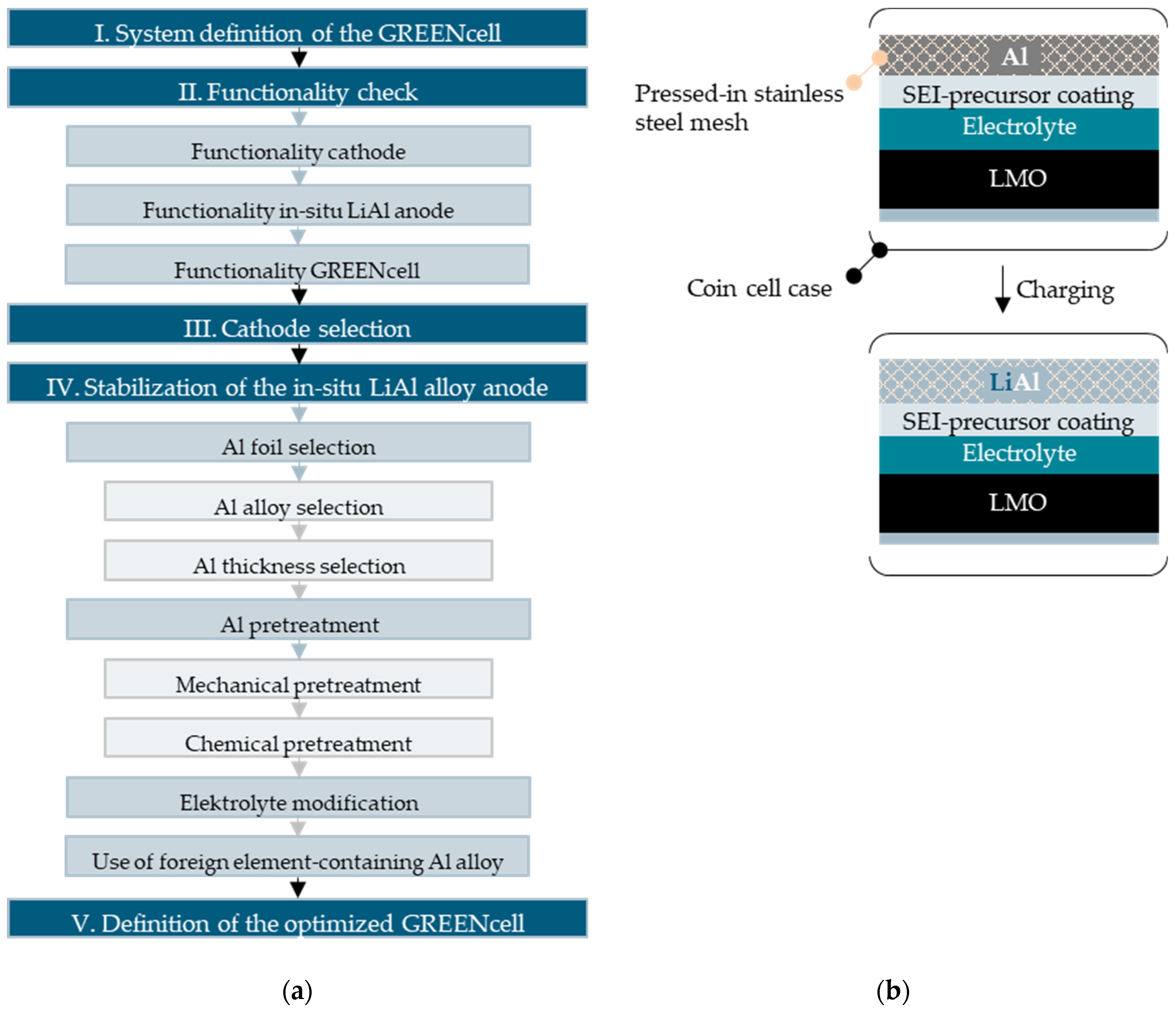
  • Mechanical pretreatment: Pressed-in stainless steel mesh;
    For mechanical pretreatment, a stainless-steel mesh (1.4301, mesh size: 0.063 mm, wire diameter: 0.028–0.04 mm, thickness: 20 µm) was pressed into the Al foil with a pneumatic lever press (Quantum Design GmbH, Darmstadt, Germany) at ~2750 kg·cm−2 at room temperature. The pressing time was 15 s. In the following sections, the pressed-in stainless steel mesh will be abbreviated to the term “mesh”.
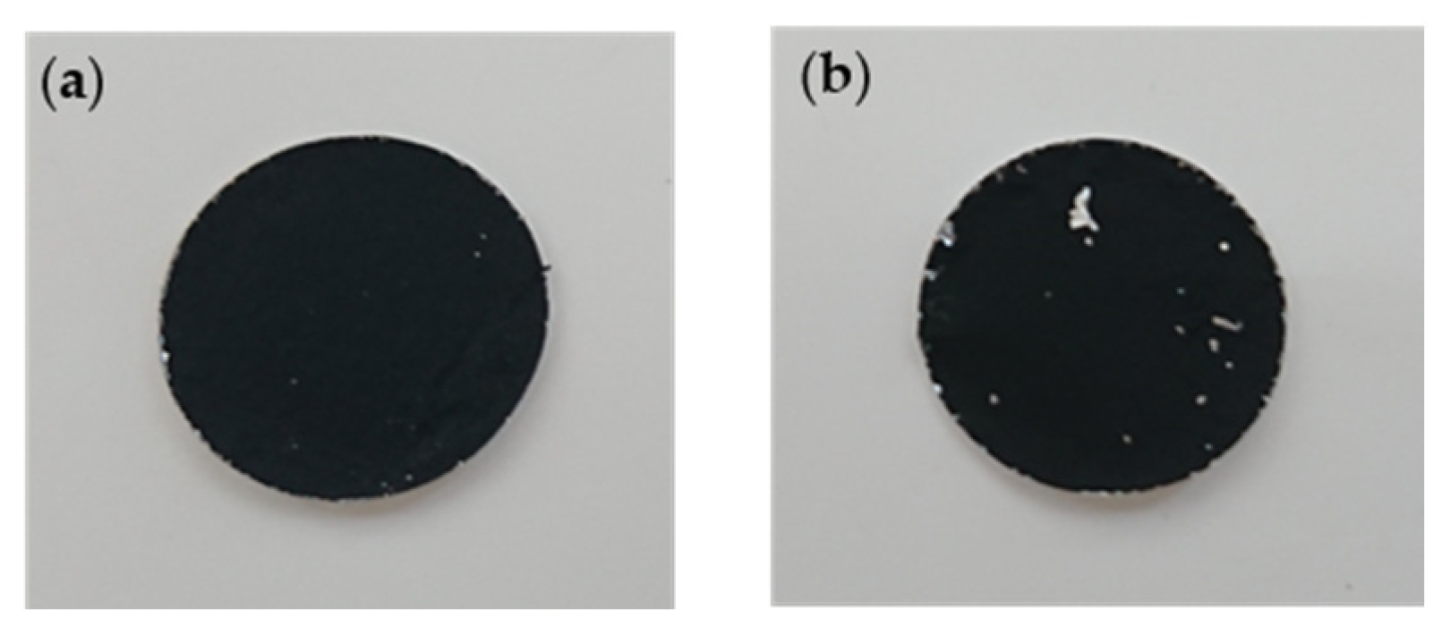
  • Chemical pretreatment: SEI-precursor coating;
    For chemical pretreatment, the Al foil was coated with an oxide-based chemical inert SEI-precursor coating. As oxide particles, Al2O3 (ρ = 3.95 g·cm−3, Ultimate 1500, Almatis GmbH, Ludwigshafen, Germany) was used for the Al-household foil. Due to adhesion problems, Al silicate (K₂Al₆Si₆O₂₀(OH)₄, ρ = 2.82 g·cm−3, Irotec 8800, flakes, Merck KGaA, Darmstadt, Germany) was used for the Al-1050A foil in the same volumetric concentration. To start, 96 wt% oxide particles were mixed with 4 wt% PIB using the 5 wt% PIB (80 wt% B15N, 20 wt% N80) solution in toluene described above. Then, Disperbyk-161 (BYK-Chemie GmbH, Wesel, Germany) was added as a dispersing additive with 12 wt%, based on a solid fraction. Finally, toluene was added to obtain a solid content of 53–56 wt%. Afterwards, the slurry was coated on the Al foil with a doctor blade (gap size: 300 µm) and dried overnight at room temperature. In the following sections, the SEI-precursor coating will be abbreviated to the term “coating”.

2.1.3. Electrolyte Preparation

The standard electrolyte lithium hexafluorophosphate in propylene carbonate (1 M LiPF6 in PC) from E-Lyte Innovations GmbH, Kaiserslautern, Germany was used. To investigate the influence of fluoroethylene carbonate (FEC, 99%, Merck KGaA, Darmstadt, Germany) on the Al anode stability, 5 wt%, 10 wt%, 15 wt%, and 25 wt% FEC electrolyte solutions were prepared. In the following sections, the FEC-modified electrolytes will be abbreviated to the term “X wt% FEC”.

2.2. Iterative GREENcell Development Process

To develop the GREENcell by combining a F-, Ni- and Co-free cathode with a stabilized LiAL alloy anode, an iterative optimization process (see Figure 1a) was followed. Iteration step I consisted of the system definition of the initial GREENcell. We defined two basic GREENcell configurations as an initial step: Al-1050A||LMO and Al-1050A||LFP. These setups involved the integration of untreated standard Al foil (20 µm Al-1050A) with the LMO and LFP cathodes, respectively. In iteration step II, the GREENcell system was examined for its functionality. As the subject of the investigations, an isolated electrochemical characterization of the cathodes and the Al anode was first carried out within the framework of half-cell tests. Subsequently, the Al anode was integrated with LMO and LFP cathodes, forming a complete GREENcell configuration, which was thoroughly examined for its functional performance. In iteration step III, the selection of the cathode’s active material for the GREENcell was determined by evaluating the cycle behavior of both half and full-cells. This evaluation aimed to identify a suitable optimization parameter and comprehend the underlying electrochemical processes within the cell. The relative discharge capacity proved to be a significant and comparable performance parameter and was therefore established as an indicator of cycle stability. The dominant weakness of the GREENcell was identified as the instability of the insitu-formed LiAl alloy anode. Consequently, the investigation of various stabilization methods constituted iteration step IV. These chosen methods for stabilization were categorized into four groups: (1) Al foil selection, (2) Al pretreatment, (3) electrolyte modification, and (4) the use of a foreign element-containing Al alloy. (1) Al foil selection encompassed an examination of how the purity of Al and the thickness of Al foil influence the stability of the LiAl alloy anode. As for (2) Al pretreatment, the effects of mechanical and chemical pretreatment were studied. The resulting cell design is shown in Figure 1b. The mechanical pretreatment consisted of a stainless-steel mesh pressed into the Al foil as an integrated three-dimensional current collector. The novel method of the pressed-in stainless steel mesh was developed to stabilize the LiAl alloy through the 3D current density distribution, the mechanical cracking of the oxide layer, and the compensation of the anode volume changes [27,28,29]. For the chemical pretreatment, an electrochemically inert coating was applied to the Al foil. The oxide-based coating is expected to form a strong and stable SEI due to its surface fixation, electrical insulation, and good ionic conductivity. In addition, the porosity is expected to improve electrolyte distribution [17,19,30,31]. The electrolyte modification, categorized as the stabilization method (3), involved the adjustment of the standard electrolyte by adding varying amounts of FEC. The presence of FEC is expected to result in the formation of a LiF and AlF3-containing SEI with improved stability [9,21,22,32]. Within the stabilization method (4) framework, a deliberate exploration into the strategic integration of foreign elements within the Al alloy was undertaken, aiming to curtail the mechanical degradation triggered by volume changes in Al. By integrating Si into the Al film, a stabilization of the anode morphology and a uniform volume change during cycling is achieved [23,24]. To still keep production costs and complexity low, a commercially available Si-low content Al alloy (Al-8011A) was investigated in this work.
Each stabilization method was characterized and evaluated by analyzing the cycle data. Based on this evaluation, a systematic, iterative decision-making process was undertaken to enhance the GREENcell system progressively. This process culminated in identifying the optimal GREENcell configuration during iteration step V.

2.3. Al Thickness Calculation

The selection of the optimal Al thickness is the tradeoff of material minimization to increase energy density and provide a sufficient Al reservoir for the in-situ formation of the LiAl alloy anode in the stoichiometric ratio of 1:1. The determination of the optimal theoretical thickness of the Al foil involved utilizing the discharge reaction equations presented in Table 1. By employing the equations and parameters provided in the Supplementary Material S1, an optimal Al foil thickness of 19.07 µm (19.34 µm for LFP) was calculated for the LMO cathode, resulting in a theoretical energy density for the GREENcell of 262.12 Wh·kg−1 (LFP: 246.54 Wh·kg−1). This value is remarkably close to that of the commercial high-energy cell Gr||NMC811 (279 Wh·kg−1), confirming the high-energy applicability of the GREENcell [5].

2.4. Electrochemical Characterization

All full-cells were electrically tested using a battery tester (Arbin Instruments, College Station, TX, USA). A constant current constant voltage (CCCV) cycling protocol was used, starting with the CC-phase at 0.1 mA with a cut-off voltage of 4.2 V for the LMO cells and 3.5 V for the LFP cells. A current of 0.05 mA limited the following CV-phase. After a break of 2 min, the cells were discharged with 0.1 mA. The discharge cut-off voltage was 3.1 V for the LMO cell and 2.5 V for the LFP cells. The same protocols were used for the half-cells with the LMO and the LFP cathode as working electrodes. The half-cells, with the Al anode as the working electrode, were cycled with a constant current (CC) protocol. They were charged and discharged with 0.05 mA with a time limit of 1.5 h for the charging and discharging step. Given the proof-of-concept nature of this study, the primary emphasis was placed on evaluating the functionality of the GREENcell system. Consequently, alongside the voltage profile, the relative discharge capacity was established as a characterization parameter. It was calculated from the quotient of the current and the maximum discharge capacity. At least two cells were constructed for each cell design, and the cell with the highest relative discharge capacity was selected. The result analysis was performed with MATLAB 2021b.

3. Results and Discussion

The results of the iterative development process of the GREENcell are presented below.

3.1. Functionality of the GREENcell

To investigate the functionality of the GREENcell system in iteration step II, the most straightforward cell design was chosen as the starting point in iteration step I. Untreated 20 µm Al-1050A foil was used as the anode and combined with the fabricated LMO and LFP cathodes to form Al-1050A||LMO- and Al-1050A||LFP-GREENcells. Al-1050A||Li, Li||LMO and Li||LFP half-cells were also built to examine the influence of the Al foil as the anode and the cathodes isolated from each other.

3.1.1. Functionality of the GREENcell Cathode Materials

Commencing with the quality analysis of the cathode materials, Figure 2 shows surface images of the cathodes punched out to the coin cell format. Due to the manual punching process, a delamination of the active material from the current collector can be observed for both the LMO cathode (a) and the LFP cathode (b). This phenomenon is particularly pronounced for the LFP cathode, possibly due to the smaller particle size of the LFP. Hence, for future experiments involving LFP, it is recommended to increase the binder content. Additionally, incorporating a calendering process can further enhance adhesion.
To evaluate the electrochemical functionality of the cathode materials, the voltage and current profiles of the Li||LMO (a) and the Li||LFP (b) half-cells are shown in Figure 3. The upper images represent the voltage and current profiles of the first five cycles, whereas the lower curves represent the progression of the first charge and discharge cycle.
The typical two-step lithiation of the LMO cathode can be seen in Figure 3a by the two voltage plateaus at 4.01 V vs. Li+/Li (20% state of charge, SOC) and 4.17 V vs. Li/Li+ (80% SOC) during charging, and 3.94 V vs. Li/Li+ and 4.12 V vs. Li/Li+ during discharging. The measured redox potentials are consistent with the characteristic redox potentials of a commercial LMO cathode, confirming the functionality of the fabricated cathode [35]. The low cathodic overpotential suggests that selecting the PIB binder has no adverse effect on the electrical conductivity and Li+ ion diffusion within the LMO cathode.
The characteristic voltage plateau of a commercial LFP cathode is about 3.4 V vs. Li/Li+ [36]. In Figure 3b, the voltage plateau of the PIB-based LFP cathode is located at 3.5 V and, therefore, is significantly higher, indicating a high cathodic overpotential. Due to the increased voltage level, the final charge voltage and, thus, the CV phase, is already reached at just under a 1% SOC, which means that the cell’s capacity cannot be fully utilized. The observed high cathode polarization is likely attributable to the inadequate adhesion of the active material on the Al current collector and the inhomogeneity of the LFP coating. This behavior aligns with the findings from the optical surface analysis shown in Figure 2.

3.1.2. Functionality of the In-Situ LiAl Alloy Anode of the GREENcell

The voltage profile of the Al-1050A||Li half-cell, presented in Figure 4a, shows the typical profile of an in-situ-formed LiAl alloy. Due to the in-situ lithiation of the Al, when forming the LiAl alloy the voltage is lowered, and the voltage plateau typical for LiAl is formed at about 0.3 V vs. Li/Li+ [9,37]. Before the plateau, the “voltage dip” mentioned by Wang et al. [7], reaching 0.09 V vs. Li/Li+, can be observed. The voltage dip is caused by the high overpotential induced by the nucleation of the LiAl alloy and the resulting slowed Li+ ion diffusion [7]. Characterized by the distinct voltage peak at the beginning of each charging phase, the effect of the voltage dip on the voltage profile of the Al-1050A||LMO (a) and Al-1050A||LFP (b) full-cells can be identified in Figure 5. Compared with the cathodic half-cells in Figure 3, the voltage profiles of the Al-1050A||LMO (a) and Al-1050A||LFP (b) full-cells in Figure 5 are lowered by 0.3 V vs. Li/Li+. This reduction aligns with the voltage profile observed in the Al-1050A||Li half-cell depicted in Figure 4 and confirms the successful in-situ formation of the LiAl alloy anode in both the LMO-GREENcell and LFP-GREENcell configurations.
When comparing the cycle duration of the LMO cells (Figure 3 and Figure 5a (top)) of the first five cycles, it is noticeable that in the case of the Al-1050A anode (Figure 5a (top)), the cycle duration is reduced from 28.3 h in the first cycle to 18.1 h in the fifth cycle. In the case of the Li anode (Figure 3a (top)), such a reduction in cycle duration is not evident. Similarly, a decrease in cycle duration from 35.8 h in the first cycle to 25.6 h in the fifth cycle can be seen for the Al-based LFP full-cell (Figure 5b (top)).
These formation losses can be attributed to the Al oxide layer on the Al-1050A surface. During initial lithiation, the Al oxide layer is electrochemically converted to Li-Al-O, which is electrically and ionically poorly conductive [7]. As a result, LiAl alloy formation is inhibited. The phenomenon manifests itself in the decrease in the discharge capacity after the initial cycles in Figure 4b.

3.2. Cathode Selection

After confirming the functionality of the GREENcell system, iteration step III was to determine the cathode material. Through half-cell tests, the specific capacitance of the LMO cathode was determined to be 80.77 Ah·kg−1, while that of the LFP cathode was 65.68 Ah·kg−1. Both values are significantly lower than the capacities exhibited by commercial LMO (110 Ah/kg) and LFP cathodes (170 Ah·kg−1) [5]. This discrepancy can be attributed to the relatively thick cathode layers (LMO: ~80 µm, LFP: ~85 µm), resulting in an increased weight contribution from excess active material. As the primary focus of this work was to establish the proof of concept for the GREENcell, further optimization of the cathode layer thickness was not pursued. However, the layer thickness optimization will be thoroughly investigated in future studies. Upon comparing the relative discharge capacities of the LMO-based full-cells Li||LMO and Al-1050A||LMO in Figure 4b, it is evident that both cells exhibit an identical capacity gradient. The capacity curve of the Al-1050A||LMO cell is shifted downwards due to an offset corresponding to the formation loss. It is suspected that the gradually declining discharge capacity over the course of multiple cycles is attributed to the LMO cathode rather than the Al anode. In the case of the LFP cathode, this behavior is not observed. The Li||LFP cell exhibits a much lower capacitance gradient than the Al-1050A||LFP cell. After 30 cycles, the relative discharge capacity of the Li||LFP cell is still 88.4%, whereas the relative discharge capacity of the Al-1050A||LFP cell is decreased to 24.0%. This behavior indicates that in the case of the LFP cathode, the Al-1050A anode significantly contributes to the cell’s long-term capacity loss. Due to lithiation, the anode undergoes non-negligible volume changes that cause structural instabilities and a decrease in the long-term cycle stability [7,8,10]. Based on these findings, it can be hypothesized that the LMO cathode stabilizes the mechanical integrity of the Al-1050A anode. One possible explanation for this observation is the stabilizing effect of Mn. The Mn of the LMO cathode is dissolved during charging by the HF acid generated by the LiPF6 electrolyte and thus reaches the anode, where it is reduced due to the low potential [12]. Incorporated as a component of the LiAl alloy, a stabilizing effect is thus exerted on the anode. This phenomenon will be further investigated in future studies.
Based on these observations, the cathode material of the GREENcell was defined as LMO. Starting with the 1050A||LMO-GREENcell, the further focus is particularly on reducing initial formation loss and long-term capacity loss. In iteration step IV, various strategies are presented to improve the cycle stability of the cell.

3.3. Methods to Improve the Cycle Stability of the In-Situ LiAl Alloy Anode

As identified in Figure 4b, the relative capacity loss of a cell with an Al-based anode is due to the following two causes: (1) high formation losses in the first cycles caused by the presence of an Al oxide layer on the surface of the Al foil. (2) Lithiation of the Al causes volume changes, resulting in structural instabilities in the anode and negatively affecting long-term cycling stability. The results presented below address the strategies implemented to improve these challenges. All cycle results below are from full-cells with the previously selected LMO cathode.

3.3.1. Al Foil Selection
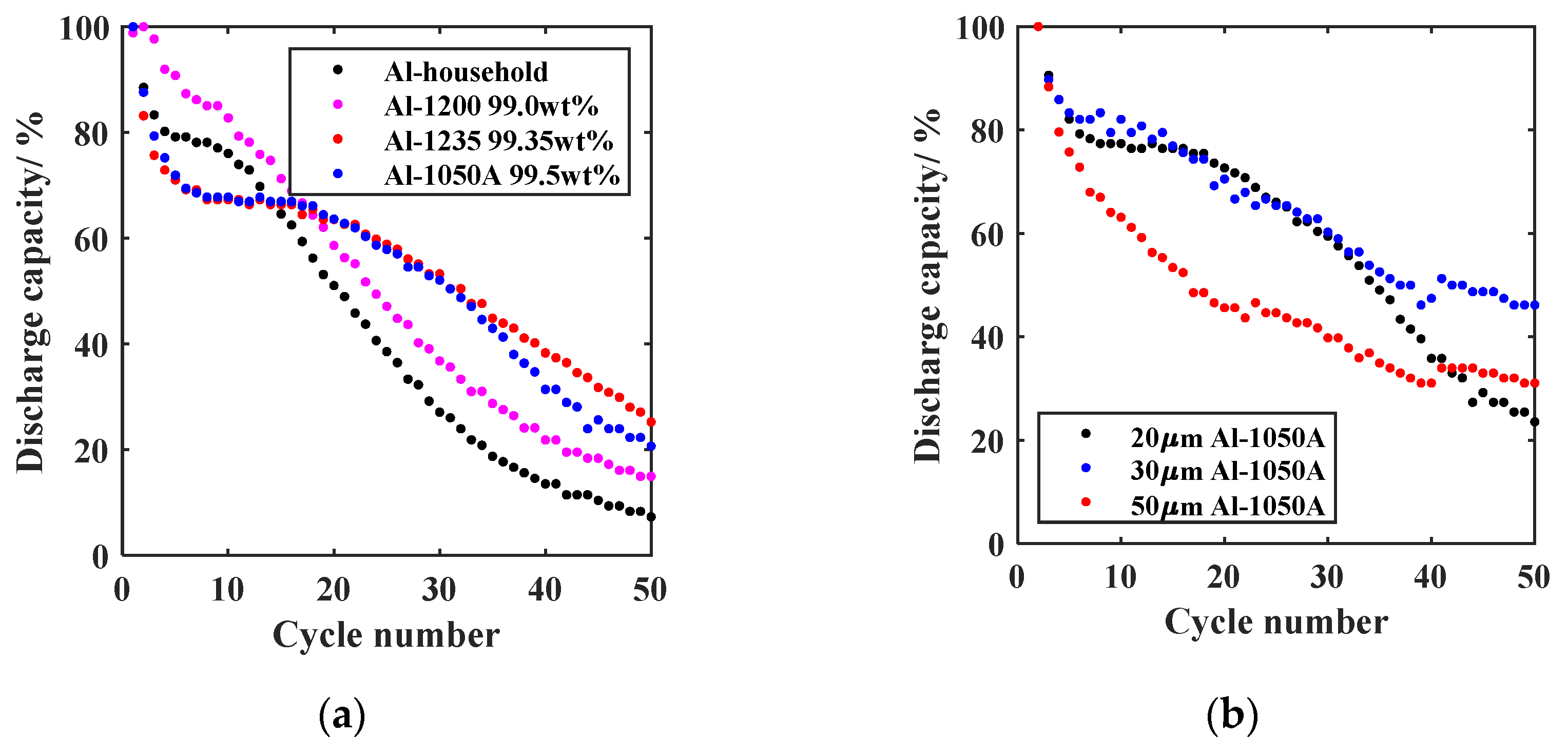
The first sub-step in iteration step IV is built by selecting the Al foil material, which can be classified into Al alloy selection and Al thickness selection.
  • Al alloy selection;
    To investigate the purity influence of the Al anode on the cycling stability of the GREENcell, the relative discharge capacity curves of different Al alloys, varying in their weight fraction of Al, are shown in Figure 6a. When comparing the long-term stability, the following order is obtained concerning the capacity retention after 50 cycles: Al-household (7.3%) < Al-1200 (14.9%) < Al-1050A (23.6%) < Al-1235 (25.2%). Up to a purity level of 99.35 wt% Al, the higher Al content appears to affect long-term stability positively. This effect can be attributed to the absence of additional elements, thereby reducing the risk of parasitic side reactions that may lead to the irreversible loss of Li. The curves of Al-1050A and Al-1235 are almost congruent, indicating that purities > 99.35 wt% Al do not cause any additional improvement. Upon evaluating the formation loss during the initial five cycles, an intriguing inverse trend emerges in terms of capacity retention: Al-1235 (71.0%) < Al-1050A (71.9%) < Al-household (79.2%) < Al-1200 (90.8%). Therefore, the additional elements in the impure Al foil appear to affect the initial capacity loss positively. However, further investigations are required to validate and provide comprehensive evidence for this observation. After considering the most promising long-term stability, the decision was made to proceed with Al-1050A Al foil to perform further optimization approaches.
  • Al thickness selection;
    Building on the theoretical considerations in Section 2.3, the second part of the Al selection consisted of the experimental investigation of the layer thickness influence. In addition to the selected 20 µm Al-1050A foil (23.6% capacity retention after 50 cycles), Al-1050A foils with a thickness of 30 µm and 50 µm were investigated as anodes of the GREENcell. The results are shown in Figure 6b. After 50 cycles, the relative discharge capacity of the 30 µm foil is 46.2%, and that of the 50 µm foil is 31.1%. Consequently, the 30 µm Al-1050A foil distinguishes itself from the other foils, solidifying its position as the new anode for the GREENcell. With reference to the calculation of the minimum Al thicknesses in Section 2.3 and the concept of DAU introduced by Zheng et al. [10], the experimental results indicate the need for an Al buffer. Therefore, the increased capacity drop of the 20 µm foil can be attributed to an insufficient Al reservoir, resulting in an exaggerated lithiation depth and inhomogeneities in the anode composition. Alloy inhomogeneities caused by Li deficiency are suspected to be the reason for the high-capacity loss of the 50 µm foil. Energy-dispersive X-ray spectroscopy (EDX) measurements should support this assumption in future observations. Based on this thickness dependence, the comparability of the results from Figure 6a must be viewed critically, as the foils employed in the alloy variation differ in thickness. However, the theory regarding the positive influence of Al purity on cycling stability is further supported by the fact that the Al-1200 foil, with a thickness of 25 µm, is even thicker than the Al-1235 and Al-1050A foils, measuring 20 µm.
Various pretreatment measures were also investigated as additional sub-steps of iteration step IV to further stabilize the 30 µm Al-1050A as the new anode of the GREENcell. For comparison purposes and their attractiveness in terms of material and manufacturing costs, the effectiveness of the pretreatment measures was additionally evaluated on 13 µm Al-household foil.

3.3.2. Al Pretreatment
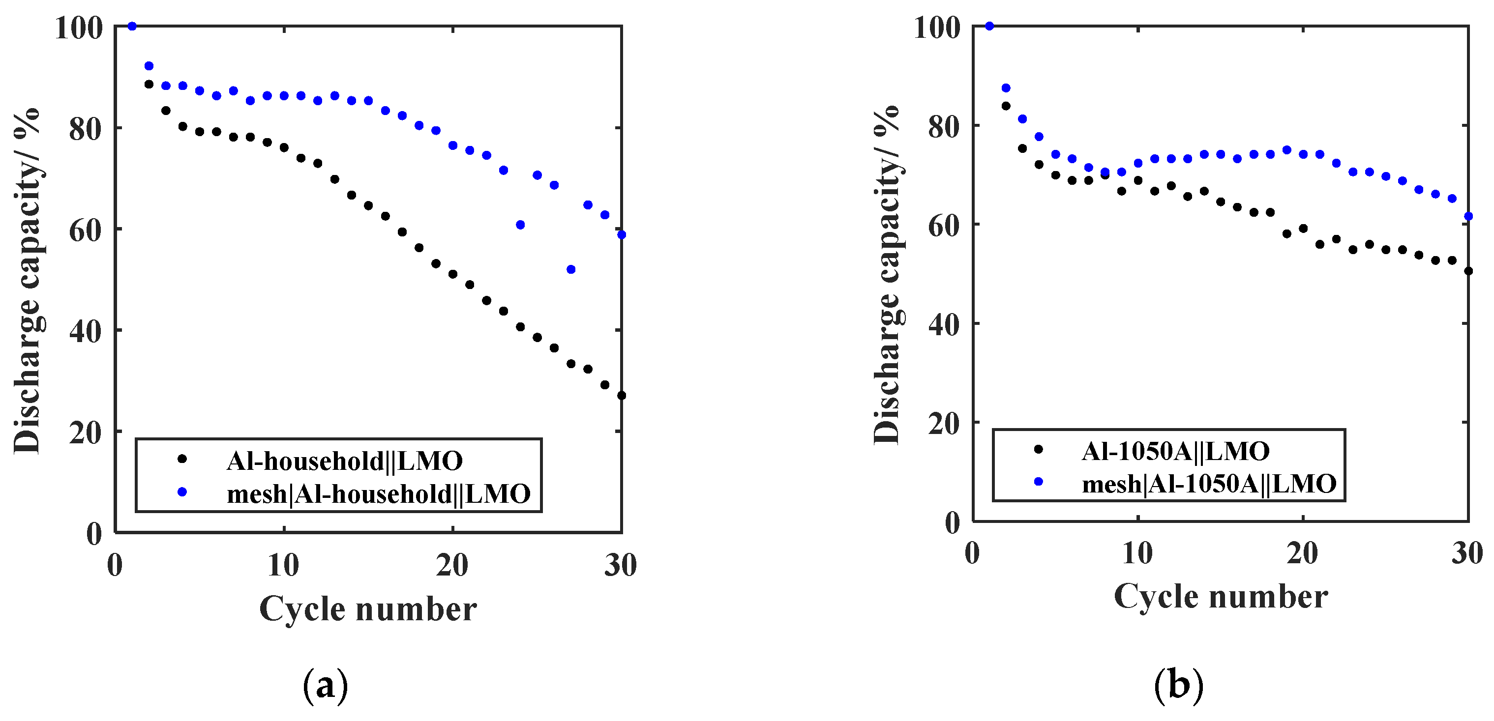
  • Mechanical pretreatment;
    The curves of the relative discharge capacity of the GREENcells whose Al anode was mechanically pretreated with a pressed-in stainless steel mesh are shown in Figure 7 for (a) Al-household and (b) Al-1050A.
    After 30 cycles, the mesh|Al-household||LMO cell exhibits a relative discharge capacity of 58.8%, a notable improvement compared to the previous 27.1% for the untreated foil. Similarly, the mesh|Al-1050A||LMO cell demonstrates a relative discharge capacity of 61.6% after 30 cycles, surpassing the previous 50.5% for the untreated foil. Using the pressed-in mesh yields a significant enhancement in cycling stability for both cases, resulting in an 11.1% increase in capacity retention for Al-1050A and a 31.7% increase for Al-household. The relatively smaller impact of the mesh on the cycling stability of the 30 µm thick Al-1050A foil can be attributed to the thinner mesh thickness of only 20 µm. A mesh that matches the Al foil thickness should be used in the future. The mesh’s effectiveness confirms the experiences of Yang et al. [29] and Lu et al. [27]. The three-dimensional current density distribution and the implied homogenization of the Li deposition as LiAl alloy over the entire bulk area of the Al foil are responsible for this positive influence [27,29]. Due to the mesh pressing into the Al foil, it can also be assumed that the mechanical breaking of the Al oxide layer on the mesh bridges intensifies the positive influence. The mechanical disruption of the Al oxide layer would also explain the reduction in the formation loss after the initial five cycles of 4.2% in the case of Al-1050A and 8.1% in the case of Al-household. Mechanical stabilization of the volumetric change is an additional explanation for the improved cycling stability. The GREENcell system was therefore updated to mesh|Al-household||LMO and mesh|Al-1050A||LMO.
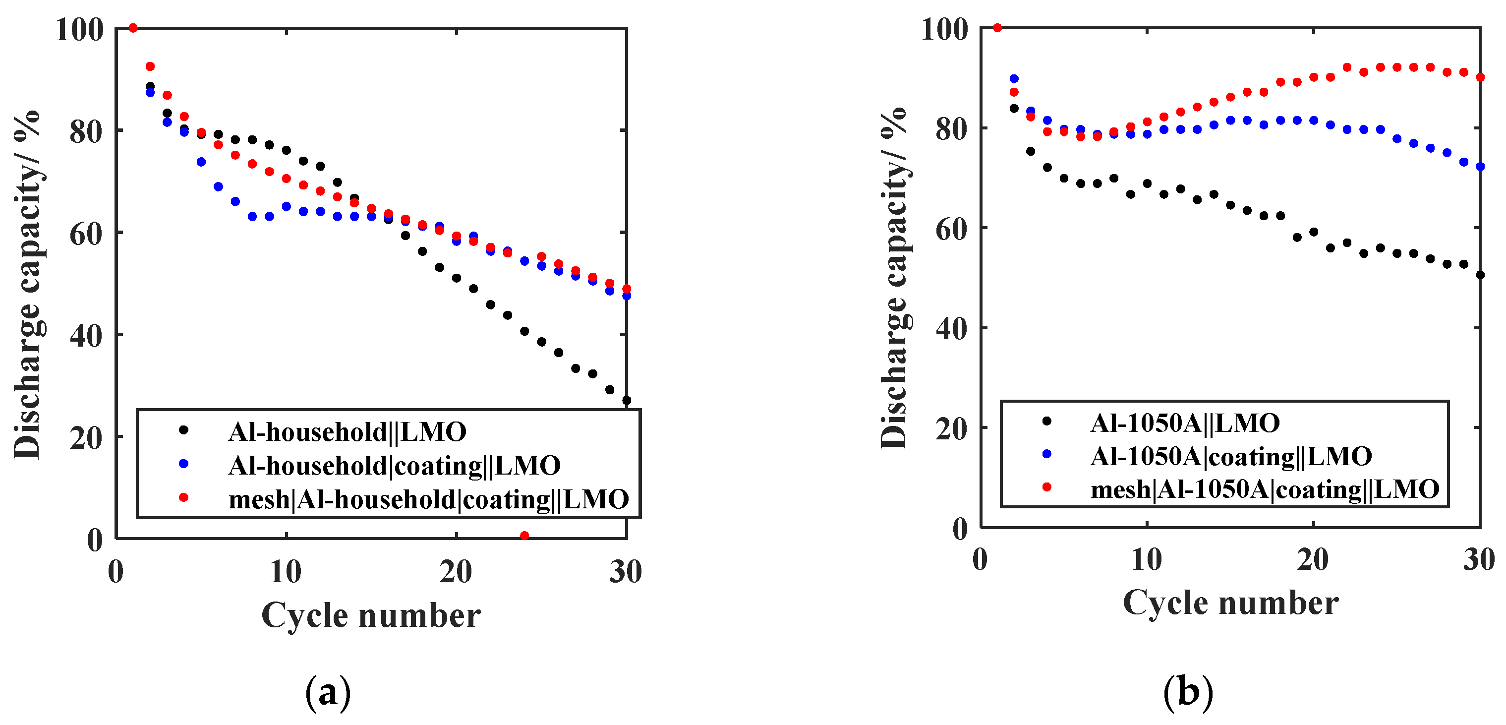
  • Chemical pretreatment;
    The curves of the relative discharge capacity of the GREENcells, where the Al anode was chemically pretreated with a SEI-precursor coating, are shown in Figure 8 for (a) Al-household and (b) Al-1050A in red. To evaluate the isolated influence of the coating on the cycling stability, plots of the relative discharge capacity of the anode design without the mesh are shown in blue.
    After 30 cycles, the relative discharge capacity of the mesh|Al-household|coating||LMO cell (red) is 48.9% compared to the 27.1% for the untreated foil (black). The mesh|Al-1050A|coating||LMO cell (red) has a relative discharge capacity of 87.1% after 30 cycles compared to 50.53% for the untreated Al foil (black). This implies a further increase in capacity retention by 25.5% compared to the previous anode design mesh|Al-1050A in Figure 7b. Additionally, the formation loss after the initial five cycles can be reduced by 9.3% compared to the untreated Al-1050A and by 5.1% compared to the mesh|Al-1050A anode design. Therefore, the effectiveness of using a SEI-precursor coating on anode stability is confirmed and agrees with the results of Liang et al. [30]. Liang et al. [30] justify the positive effect of an artificially applied oxide coating with the stability increase in the SEI, improved ionic conductivity, and electrolyte distribution at the electrode/electrolyte interface.
    For both the Al-household foil and the Al-1050A foil, the curves with (red) and without mesh (blue) are very close. Using the mesh-coating combination, the relative discharge capacity can be increased by 1.3% for Al-household and 5.6% for Al-1050A after 30 cycles compared to just using the coating. This slight improvement in the case of the Al-household lies in the area of tolerance and does not allow a clear decision to be made. Since the goal was to define an optimal GREENcell system, the decision-making was based on the promising results of the Al-1050A foil. Thus, the new anode design was set to mesh|Al-household|coating and mesh|Al-1050A|coating. To statistically support this decision, further cells will be built in the future.

3.3.3. Electrolyte Modification

The curves of the relative discharge capacity of the GREENcells with a FEC-modified electrolyte are shown in Figure 9 for (a) Al-household and (b) Al-1050A.
With the addition of FEC, there is a significant reduction in capacity loss when using the Al-household foil. After 30 cycles, the relative discharge capacity is 61.9% with an electrolyte mixture containing 5 wt% FEC, 68.3% with 10 wt% FEC, and 70.4% with 25 wt% FEC. After the initial five cycles, the relative discharge capacities are 79.6% (0 wt% FEC) < 86.1% (10 wt% FEC) < 88.3% (25 wt% FEC) < 89.6% (5 wt%). Therefore, the FEC-rich electrolyte can further improve the cycling stability and decrease the formation loss, which is consistent with the observations of Choi et al. [22]. The LiAl-stabilizing effect of the FEC-containing electrolyte can be attributed to forming an AlF3- and LiF-rich SEI [7,31,32]. Both components promote the formation of a strong, stable SEI. The SEI can, therefore, better withstand the volume change of the anode. For up to 30 cycles, the three curves differ slightly, indicating that even a small amount of FEC can achieve a positive effect. Thus, increasing the FEC content to >5 wt% has only a minor effect. In the case of the Al-1050A foil, the profiles of the relative discharge capacity are all very close together, with 46.6% (15 wt% FEC) < 50.5% (25 wt% FEC) < 52.0% (0% FEC). An electrolyte containing FEC even seems to negatively influence the cycle stability here. This observation shows that the cycle behavior and, thus, the effectiveness of the optimization strategies strongly depend on the choice of the Al foil material due to overlapping effects. The addition of FEC was not pursued further for the Al-1050A foil. Therefore, as an intermediate result, depending on the Al foil selection, two different optimized anode designs are obtained: for the Al-household foil, the optimal anode was determined to be (1) Al-household|coating|25 wt% FEC and for the Al-1050A, (2) mesh|Al-1050A|coating.

3.3.4. Foreign Element-Containing Al Alloy

To further enhance the long-term cycle stability of the GREENcell, we investigated the impact of foreign element-containing Al alloys starting with untreated Si-containing Al foil (Al-8011A) as the anode. The curve of the relative discharge capacity of the resulting GREENcell is presented in Figure 10. Utilizing the Al-8011A foil enables a capacity retention of 64.9% after 60 cycles, signifying a substantial 32.6% improvement over the untreated high-purity Al-1050A foil. Given the efficacy of introducing Si into the Al alloy, the configuration Al-8011A||LMO emerges as the new most promising design for the GREENcell. The significant increase in stability can be attributed to the structural change of the Al alloy due to the presence of Si. It is assumed that Si has a counterpart contribution to the volume change of the Al during lithiation and delithiation, slowing down the stress-induced mechanical degradation of the anode. The results are consistent with the work of Tahmasebi et al. [23], where it has been stated that using a 70 wt% Al- 30 wt% Si alloy leads to a stable anode morphology and a uniform volume expansion/contraction. Further studies are needed to gain a more comprehensive understanding of the volumetric and structural effects that occur during the cycling of Al alloys with a low Si content (<1 wt%). Examining the formation loss after the first five cycles, the Al-8011A foil with a capacity retention of 74.2% shows a similar behavior to the untreated high-purity Al-1050A foil. These pronounced formation losses align with findings observed in the analysis of the other untreated foils, thereby motivating the future application of the mechanical and chemical pretreatment techniques on the optimized GREENcell Al-8011A||LMO.

3.4. Optimized In-Situ Li-Al Alloy Anode of the GREENcell

Figure 10 shows the significant improvement in formation loss and long-term cycle stability of the three optimized GREENcells achieved through the iterative development process: (1) mesh|Al-household|coating|25 wt% FEC||LMO, (2) mesh|Al-1050A|coating||LMO, and (3) Al-8011A||LMO. For Al-household (black), capacity retention can be increased by 25% after 60 cycles by using the optimized anode mesh|Al-household|coating|25 wt% FEC compared to the untreated Al-household. For Al-1050A (blue), the increase in capacity retention using the optimized anode mesh|Al-1050A|coating is 14.3% after 60 cycles. Consequently, the capacity retention of the optimized GREENcells mesh|Al-household|coating|25 wt% FEC||LMO and mesh|Al-1050A|coating||LMO results in 25.8% and 46.5%, respectively, after 60 cycles. The difference in capacity can be attributed to using different Al foil materials. Thus, it seems that the influence of foil purity and thickness, shown in Section 3.3.1, is further amplified over the course of additional cycles. The application of the optimized anodes, both for the Al-1050A and the Al-household foil, reduces the formation loss by ~10% after the first five cycles.
Compared to the optimized Al-1050A anode, mesh|Al-1050A|coating, the utilization of Si-containing Al-8011A foil (green) leads to a further 19% enhancement in capacity retention after 60 cycles. Therefore, the Al-8011A||LMO configuration emerges as the most promising among the optimized GREENcell systems. After further investigating the long-term stability of the Al-8011A configuration, a capacity retention of 74.2% after 200 cycles is observed, further highlighting the feasibility of the GREENcell.
The functionality and positive impact of the stabilization methods on the cycling stability of the GREENcell demonstrate the potential of this new cell technology. Consequently, the potential for further reduction in the formation loss within the optimized Al-8011A||LMO GREENcell configuration serves as a compelling impetus to pursue our iterative optimization process. Given the previously established confirmation of decreasing formation losses through the utilization of a pressed-in mesh along with a SEI-precursor coating, we intend to apply these pretreatment methodologies to the Al-8011A anode in forthcoming investigations. Following the idea of Zheng et al. [13], we see further potential for anodic stabilization in optimizing the charge and discharge operating window for better utilization of Li solubility in the LiAl alloy phase. On the cathode side, the coating quality is identified as an optimization parameter for the future. Integrating a calendering process is expected to enhance adhesion to the current collector and improve porosity. These improvements are anticipated to impact reproducibility as well positively.

4. Conclusions

In summary, we demonstrated the first proof of concept for a novel cell system, the GREENCell, which combines sustainability and energy density by utilizing a F-free, Ni-free, and Co-free cathode, along with a stabilized in-situ LiAl alloy anode. Through an iterative process, the optimal configuration of the GREENCell was developed.
Both LFP and LMO, with an environmentally friendly PIB binder material, were evaluated as potential cathode materials. The LMO cathode exhibited superior coating and cycling properties compared to the LFP cathode, leading to the selection of LMO as the preferred cathode material for the GREENCell. By combining the LMO cathode with an in-situ LiAl alloy anode to the Al||LMO cell system, the issue of Mn dissolution commonly associated with commercial Gr anodes was effectively harnessed. Additionally, with 262.12 Wh·kg−1, the Al||LMO systems come remarkably close to the theoretical energy density of the commercial high-energy cell Gr||NMC811 (279 Wh·kg−1), confirming the high-energy applicability of the GREENcell. To the best of our knowledge, the Al||LMO cell system is being studied for the first time in this work. To improve the cycle stability issues of Al-based anodes, the following stabilization strategies were investigated for their effectiveness: Al foil selection, Al pretreatment, electrolyte modification, and the use of a foreign element-containing Al alloy. The significant influence of foil purity and thickness on reversible cell capacity was observed during the iteration step Al foil selection. The Al foil Al-1050A with a maximum Al content of 99.5% and a thickness of 30 µm proved the most promising. Due to the high availability and low costs, Al-household foil was investigated as an additional possible anode of the GREENcell. A pressed-in stainless-steel mesh was used as a mechanical pretreatment for the Al foil. The mesh implementation has demonstrated effectiveness, resulting in a capacity retention increase of 31.7% and 11.1% after 30 cycles for the Al-household and Al-1050A foils, respectively. The Al foil was chemically pretreated using a SEI-precursor coating of electrochemically inactive binder-stabilized oxide particles. For the Al-1050A foil, the utilization of the mesh-coating pretreatment combination led to a 36.57% increase in capacity retention after 30 cycles, surpassing the performance of untreated Al-1050A. Conversely, the coating exhibited only a marginal enhancement in cyclic stability for the Al-household foil. The impact of electrolyte modification using a FEC-containing electrolyte varied between the Al-household and Al-1050A foils. Introducing a 25 wt% FEC content resulted in a substantial 21.4% increase in capacity retention after 30 cycles for the Al-household foil. However, no significant improvement was observed for the Al-1050A foil under the same conditions. The varying effectiveness of stabilization strategies from Al-household and Al-1050A can be attributed to the foil thickness and purity differences and underpins their influence on anode stability.
As an intermediate result of our iterative optimization process, the optimized GREENcell systems mesh|Al-household|coating|25 wt% FEC||LMO for Al-household and mesh|Al-1050A|coating||LMO for Al-1050A were identified. To further improve cycle stability, the Si-containing Al alloy Al-8011A was introduced as an anode, increasing capacity retention further by 19% after 60 cycles. The long-term stability resulted in a capacity retention of 74.2% after 200 cycles. As a final result of the iterative optimization process, the GREENcell design was therefore set to Al-8011A||LMO. When using a LiAl anode in a full-cell, the cycle life has so far only been surpassed through the use of foreign elements in an artificially fabricated Al film, the utilization of a cost intense prelithiation step, or the use of F-containing cathode materials [7,8,10,25,38].
Based on the demonstrated sustainable and high-energy characteristics, the successful identification of effective stabilization methods, as well as the development of a stable Al||LMO cell, we are highly optimistic about the future prospects of the GREENcell. To further minimize the initial capacity loss while maintaining cost-effectiveness and simplicity in cell production, we aim to explore the utilization of the discussed mechanical and chemical pretreatment methods on the Al-8011A anode. In addition, we see further potential for improvement in optimizing the charge and discharge operating window for better utilization of Li solubility in the LiAl alloy phase.

5. Patents

The patent DE 10 2022 209 366.6 with the title “Verfahren zur Herstellung einer negativen Elektrode, negative Elektrode, galvanische Zelle und Verwendungen der galvanischen Zelle” was submitted on 8 September 2022. The patent addresses, among other things, the methods of the pressed-in stainless-steel mesh combined with the SEI-precursor coating to form a stabilized LiAl alloy anode.

Supplementary Materials

The following supporting information can be downloaded at: https://www.mdpi.com/article/10.3390/batteries9090453/s1, Supplementary Material S1: Al thickness calculation.

Author Contributions

Conceptualization, K.S.; methodology, K.S.; investigation, K.S.; experimental, K.S. and D.W.; data curation and analysis, K.S.; resources, K.S. and K.P.B.; writing—original draft preparation, K.S.; writing—review and editing, K.P.B. and D.W.; visualization, K.S.; supervision, K.P.B.; project administration, K.S.; funding acquisition, K.P.B. and K.S. All authors have read and agreed to the published version of the manuscript.

Funding

The authors wish to thank the Ministry of Economic Affairs, Labour and Tourism in Baden-Württemberg for funding this work under the funding code BW1_1208/02 as part of the research project “SEEDBattery”. The financial support is gratefully acknowledged.

Data Availability Statement

The data presented in this study are available within the article and the Supplementary Materials.

Acknowledgments

The authors thank Duygu Karabelli for her support in defining the cathode recipe, the initial SEI-precursor coating recipe, and the initial cell development. In addition, we thank Eugenia Komnik for her support in reviewing this article.

Conflicts of Interest

The authors declare no conflict of interest.

References

  1. Murdock, B.E.; Toghill, K.E.; Tapia-Ruiz, N. A Perspective on the Sustainability of Cathode Materials used in Lithium-Ion Batteries. Adv. Energy Mater. 2021, 11, 2102028. [Google Scholar] [CrossRef]
  2. Dühnen, S.; Betz, J.; Kolek, M.; Schmuch, R.; Winter, M.; Placke, T. Toward Green Battery Cells: Perspective on Materials and Technologies. Small Methods 2020, 4, 2000039. [Google Scholar] [CrossRef]
  3. Agora Verkehrswende. Lithium-Ionen-Batterien—CO2-Emissionen Durch Fertigung 2019|Statista: Zusammensetzung der Treibhausgas-Emissionen in der Herstellung von Batterien für Elektroautos nach Bestandteilen/Fertigungsschritten (in kg CO2-Äquivalenten pro kWh der Batterie; Stand: 2019). Available online: https://de.statista.com/statistik/daten/studie/1074324/umfrage/zusammensetzung-der-co2-emissionen-bei-der-herstellung-von-e-autobatterien/ (accessed on 25 June 2023).
  4. Chagnes, A.; Pospiech, B. A brief review on hydrometallurgical technologies for recycling spent lithium-ion batteries. J. Chem. Technol. Biotechnol. 2013, 88, 1191–1199. [Google Scholar] [CrossRef]
  5. Miao, Y.; Hynan, P.; von Jouanne, A.; Yokochi, A. Current Li-Ion Battery Technologies in Electric Vehicles and Opportunities for Advancements. Energies 2019, 12, 1074. [Google Scholar] [CrossRef]
  6. Wentker, M.; Greenwood, M.; Leker, J. A Bottom-Up Approach to Lithium-Ion Battery Cost Modeling with a Focus on Cathode Active Materials. Energies 2019, 12, 504. [Google Scholar] [CrossRef]
  7. Wang, H.; Tan, H.; Luo, X.; Wang, H.; Ma, T.; Lv, M.; Song, X.; Jin, S.; Chang, X.; Li, X. The progress on aluminum-based anode materials for lithium-ion batteries. J. Mater. Chem. A 2020, 8, 25649–25662. [Google Scholar] [CrossRef]
  8. Chen, S.; Yang, X.; Zhang, J.; Ma, J.; Meng, Y.; Tao, K.; Li, F.; Geng, J. Aluminum–lithium alloy as a stable and reversible anode for lithium batteries. Electrochim. Acta 2021, 368, 137626. [Google Scholar] [CrossRef]
  9. Zhang, W.-J. A review of the electrochemical performance of alloy anodes for lithium-ion batteries. J. Power Source 2011, 196, 13–24. [Google Scholar] [CrossRef]
  10. Zheng, T.; Boles, S.T. Lithium aluminum alloy anodes in Li-ion rechargeable batteries: Past developments, recent progress, and future prospects. Prog. Energy 2023, 5, 032001. [Google Scholar] [CrossRef]
  11. Insider Inc.; finanzen.net GmbH. Aluminium PRICE Today|Aluminium Spot Price Chart|Live Price of Aluminium per Ounce|Markets Insider. Available online: https://markets.businessinsider.com/commodities/aluminum-price?op=1 (accessed on 22 June 2023).
  12. Amine, K.; Liu, J.; Kang, S.; Belharouak, I.; Hyung, Y.; Vissers, D.; Henriksen, G. Improved lithium manganese oxide spinel/graphite Li-ion cells for high-power applications. J. Power Source 2004, 129, 14–19. [Google Scholar] [CrossRef]
  13. Zheng, T.; Kramer, D.; Mönig, R.; Boles, S.T. Aluminum Foil Anodes for Li-Ion Rechargeable Batteries: The Role of Li Solubility within β-LiAl. ACS Sustain. Chem. Eng. 2022, 10, 3203–3210. [Google Scholar] [CrossRef]
  14. Chen, T.; Thenuwara, A.C.; Yao, W.; Sandoval, S.E.; Wang, C.; Kang, D.H.; Majumdar, D.; Gopalaswamy, R.; McDowell, M.T. Benchmarking the Degradation Behavior of Aluminum Foil Anodes for Lithium-Ion Batteries. Batter. Supercaps 2023, 6, e202200363. [Google Scholar] [CrossRef]
  15. Min, Z.; Jiege, L.; Bin, Y. A Kind of Three-Dimensional Porous Lithium Metal Composite Negative Pole Material and Preparation Method and Application. Chinese Patent CN109244374A, 31 July 2018. [Google Scholar]
  16. Li, Q.; Zhu, S.; Lu, Y. 3D Porous Cu Current Collector/Li-Metal Composite Anode for Stable Lithium-Metal Batteries. Adv. Funct. Mater. 2017, 27, 1606422. [Google Scholar] [CrossRef]
  17. Ling, H.Y.; Su, Z.; Chen, H.; Hencz, L.; Zhang, M.; Tang, Y.; Zhang, S. Biomass-Derived Poly(Furfuryl Alcohol)–Protected Aluminum Anode for Lithium-Ion Batteries. Energy Technol. 2019, 7, 1800995. [Google Scholar] [CrossRef]
  18. Jiang, M.; Yu, Y.; Fan, H.; Xu, H.; Zheng, Y.; Huang, Y.; Li, S.; Li, J. Full-Cell Cycling of a Self-Supporting Aluminum Foil Anode with a Phosphate Conversion Coating. ACS Appl. Mater. Interfaces 2019, 11, 15656–15661. [Google Scholar] [CrossRef]
  19. Salehan, S.S.; Nadirah, B.N.; Saheed, M.S.M.; Yahya, W.Z.N.; Shukur, M.F. Conductivity, structural and thermal properties of corn starch-lithium iodide nanocomposite polymer electrolyte incorporated with Al2O3. J. Polym. Res. 2021, 28, 222. [Google Scholar] [CrossRef]
  20. Fan, H.; Chen, B.; Li, S.; Yu, Y.; Xu, H.; Jiang, M.; Huang, Y.; Li, J. Nanocrystalline Li–Al–Mn–Si Foil as Reversible Li Host: Electronic Percolation and Electrochemical Cycling Stability. Nano Lett. 2020, 20, 896–904. [Google Scholar] [CrossRef]
  21. Morita, M.; Shibata, T.; Yoshimoto, N.; Ishikawa, M. Anodic behavior of aluminum in organic solutions with different electrolytic salts for lithium ion batteries. Electrochim. Acta 2002, 47, 2787–2793. [Google Scholar] [CrossRef]
  22. Choi, N.-S.; Yew, K.H.; Lee, K.Y.; Sung, M.; Kim, H.; Kim, S.-S. Effect of fluoroethylene carbonate additive on interfacial properties of silicon thin-film electrode. J. Power Source 2006, 161, 1254–1259. [Google Scholar] [CrossRef]
  23. Tahmasebi, M.H.; Kramer, D.; Geßwein, H.; Zheng, T.; Leung, K.-C.; Lo, B.T.W.; Mönig, R.; Boles, S.T. In situ formation of aluminum–silicon–lithium active materials in aluminum matrices for lithium-ion batteries. J. Mater. Chem. A 2020, 8, 4877–4888. [Google Scholar] [CrossRef]
  24. Fleischauer, M.D.; Obrovac, M.N.; Dahn, J.R. Al–Si Thin-Film Negative Electrodes for Li-Ion Batteries. J. Electrochem. Soc. 2008, 155, A851–A854. [Google Scholar] [CrossRef]
  25. Zhang, M.; Xiang, L.; Galluzzi, M.; Jiang, C.; Zhang, S.; Li, J.; Tang, Y. Uniform Distribution of Alloying/Dealloying Stress for High Structural Stability of an Al Anode in High-Areal-Density Lithium-Ion Batteries. Adv. Mater. 2019, 31, e1900826. [Google Scholar] [CrossRef] [PubMed]
  26. Lou, D.; Hong, H.; Ellingsen, M.; Hrabe, R. Supersonic cold-sprayed Si composite alloy as anode for Li-ion batteries. Appl. Phys. Lett. 2023, 122, 023901. [Google Scholar] [CrossRef]
  27. Lu, Z.; Li, W.; Long, Y.; Liang, J.; Liang, Q.; Wu, S.; Tao, Y.; Weng, Z.; Lv, W.; Yang, Q. Constructing a High-Strength Solid Electrolyte Layer by In Vivo Alloying with Aluminum for an Ultrahigh-Rate Lithium Metal Anode. Adv. Funct. Mater. 2019, 30, 1907343. [Google Scholar] [CrossRef]
  28. Zhang, S.; Xing, Y.; Jiang, T.; Du, Z.; Li, F.; He, L.; Liu, W. A three-dimensional tin-coated nanoporous copper for lithium-ion battery anodes. J. Power Source 2011, 196, 6915–6919. [Google Scholar] [CrossRef]
  29. Yang, C.-P.; Yin, Y.-X.; Zhang, S.-F.; Li, N.-W.; Guo, Y.-G. Accommodating lithium into 3D current collectors with a submicron skeleton towards long-life lithium metal anodes. Nat. Commun. 2015, 6, 8058. [Google Scholar] [CrossRef]
  30. Liang, X.; Yang, Y.; Jin, X.; Huang, Z.; Kang, F. The high performances of SiO2/Al2O3-coated electrospun polyimide fibrous separator for lithium-ion battery. J. Membr. Sci. 2015, 493, 1–7. [Google Scholar] [CrossRef]
  31. Gu, X.; Dong, J.; Lai, C. Li-containing alloys beneficial for stabilizing lithium anode: A review. Eng. Rep. 2021, 3, e12339. [Google Scholar] [CrossRef]
  32. Hou, T.; Yang, G.; Rajput, N.N.; Self, J.; Park, S.-W.; Nanda, J.; Persson, K.A. The influence of FEC on the solvation structure and reduction reaction of LiPF6/EC electrolytes and its implication for solid electrolyte interphase formation. Nano Energy 2019, 64, 103881. [Google Scholar] [CrossRef]
  33. Tran, M.-K.; DaCosta, A.; Mevawalla, A.; Panchal, S.; Fowler, M. Comparative Study of Equivalent Circuit Models Performance in Four Common Lithium-Ion Batteries: LFP, NMC, LMO, NCA. Batteries 2021, 7, 51. [Google Scholar] [CrossRef]
  34. Karabelli, D.; Birke, K.P. Feasible Energy Density Pushes of Li-Metal vs. Li-Ion Cells. Appl. Sci. 2021, 11, 7592. [Google Scholar] [CrossRef]
  35. Flamme, B.; Yeadon, D.J.; Phadke, S.; Anouti, M. Effect of fluorinated additives or co-solvent on performances of graphite//LiMn2O4 cells cycled at high potential. J. Energy Chem. 2021, 52, 332–342. [Google Scholar] [CrossRef]
  36. Hu, S.; Li, Y.; Yin, J.; Wang, H.; Yuan, X.; Li, Q. Effect of different binders on electrochemical properties of LiFePO4/C cathode material in lithium ion batteries. Chem. Eng. J. 2014, 237, 497–502. [Google Scholar] [CrossRef]
  37. Rao, B.M.L.; Francis, R.W.; Christopher, H.A. Lithium-Aluminum Electrode. J. Electrochem. Soc. 1977, 124, 1490–1492. [Google Scholar] [CrossRef]
  38. Ji, B.; Zhang, F.; Sheng, M.; Tong, X.; Tang, Y. A Novel and Generalized Lithium-Ion-Battery Configuration utilizing Al Foil as Both Anode and Current Collector for Enhanced Energy Density. Adv. Mater. 2017, 29, 1604219. [Google Scholar] [CrossRef]
Figure 1. (a) Iterative development and optimization process of the GREENcell; (b) schematic illustration of the GREENcell cell system using Al pretreatment as stabilization method, e.g., with an LMO cathode.
Batteries 09 00453 g001
Figure 2. Surface images of the developed PIB-based (a) LMO and (b) LFP cathodes after manual punching out to the coin cell format.
Batteries 09 00453 g002
Figure 3. (Top): Voltage and current profiles of the (a) Li||LMO and the (b) Li||LFP half-cells are shown. (Bottom): First charge and discharge cycle of the (a) Li||LMO and the (b) Li||LFP half-cells.
Batteries 09 00453 g003
Figure 4. (a) Voltage profile of the Al-1050A||Li half-cell. (b) Relative discharge capacity curves of the Li||LMO and Li||LFP half-cells and the Al-1050A||LMO and Al-1050A||LFP full-cells.
Batteries 09 00453 g004
Figure 5. (Top): Voltage and current profiles of the (a) Al-1050A||LMO and the (b) Al-1050A||LFP full-cells are shown. (Bottom): First charge and discharge cycle of the (a) Al-1050A||LMO and the (b) Al-1050A||LFP full-cells.
Batteries 09 00453 g005
Figure 6. (a) Relative discharge capacity curves of Al||LMO-GREENcells using different Al alloys, varying in their weight fraction of Al (Al-1200, Al-1235, Al-1050A). (b) Relative discharge capacity curves of Al-1050A||LMO-GREENcells using foils of different thicknesses (20 µm, 30 µm, and 50 µm).
Batteries 09 00453 g006
Figure 7. Relative discharge capacity curves of Al||LMO-GREENcells using (a) untreated Al-household and mesh|Al-household and (b) untreated Al-1050A and mesh|Al-1050A as the anode.
Batteries 09 00453 g007
Figure 8. Relative discharge capacity curves of Al||LMO-GREENcells using (a) untreated Al-household, Al-household|coating and mesh|Al-household|coating and (b) untreated Al-1050A, Al-1050A|coating and mesh|Al-1050A|coating as the anode.
Batteries 09 00453 g008
Figure 9. Relative discharge capacity curves of Al ||LMO-GREENcells using a modified electrolyte with varying content of FEC. (a) Mesh|Al-household|coating as the anode using 0–25 wt% FEC content in the electrolyte; (b) Al-1050A as the anode using 0–25 wt% FEC content.
Batteries 09 00453 g009
Figure 10. Relative discharge capacity curves of the initial Al ||LMO-GREENcells using untreated Al-household and Al-1050A (dots) as the anode and the optimized Al||LMO-GREENcells using mesh|Al-household|coating|25 wt% FEC, mesh|Al-1050A|coating and Al-8011A||LMO as the anode.
Batteries 09 00453 g010
Table 1. Calculated optimal Al thickness and resulting energy densities using a LiAl anode and LMO/LFP cathodes.
AnodeCathodeDischarge Reaction Energy Density *Al Thickness *
LiAlLMOLiAl + 2 Li0.5Mn0.5O4 → Al + 2 LiMn2O4 [33]262.12 Wh·kg−119.07 µm
LiAlLFPLiAl + 2 Li0.5FePO4 → Al + 2 LiFePO4 [33]246.54 Wh·kg−119.39 µm
* For detailed calculation, see Supplementary Material S1. The approach is based on the procedure for calculating the Li deposition thickness according to Karabelli et al. [34].
Disclaimer/Publisher’s Note: The statements, opinions and data contained in all publications are solely those of the individual author(s) and contributor(s) and not of MDPI and/or the editor(s). MDPI and/or the editor(s) disclaim responsibility for any injury to people or property resulting from any ideas, methods, instructions or products referred to in the content.

