Article

State of Charge Estimation for Lithium-Ion Battery Based on Unscented Kalman Filter and Long Short-Term Memory Neural Network

School of Control Science and Engineering, Shandong University, Jinan 250061, China
*
Author to whom correspondence should be addressed.
Batteries 2023, 9(7), 358; https://doi.org/10.3390/batteries9070358
Submission received: 5 April 2023 / Revised: 3 June 2023 / Accepted: 20 June 2023 / Published: 4 July 2023
(This article belongs to the Special Issue Battery Management System for Electric Vehicles)

Abstract

:
State of charge (SOC) estimation is the core algorithm of the battery management system. However, the commonly used model-based, data-driven, or experiment-based methods struggle to independently achieve accurate SOC estimation under different working conditions and temperatures, which affects battery performance and safety. To this end, this paper proposes an online SOC estimation method that combines the model-driven and double-data-driven approaches. The unscented Kalman filter (UKF) based on the first-order RC model is used to achieve robust SOC estimation, while the data-driven long short-term memory (LSTM) neural network is used to achieve fast SOC estimation. The former model has an excellent dynamic performance and the latter has high steady-state accuracy. The SOC estimation results are input into the SOC estimation model of series LSTM so that the stable but inaccurate SOC values estimated by UKF in the first part and the accurate but fluctuating SOC values estimated by LSTM can be correlated and corrected, achieving a fast and accurate SOC estimation under various working conditions. The estimation results show that the above method has strong robustness and high accuracy, and effectively reduces model complexity and data redundancy. In addition, the root mean square error of SOC estimation under different working conditions is controlled within 1–2.3% at 0 °C, 25 °C, and 45 °C, which is better than the traditional single-SOC estimation method.

Graphical Abstract

1. Introduction

The popularization of electric drive equipment led to the research boom regarding energy storage equipment. Among these, the lithium-ion battery has garnered significant attention due to its high energy density, long cycle life, and other benefits [1]. State of charge (SOC), as an important parameter to ensure the safe and stable operation of the battery, is the main focus of battery research [2]. The present research methods for SOC estimation can be classified into three categories: experiment-based methods, model-based methods, and data-driven methods [3].
The experiment-based method employs the impedance spectrum method, residual capacity method, open-circuit voltage (OCV) method, ampere-hour counting (AH) method, and other methods to establish the mapping relationship between external parameter characteristics and SOC [4,5,6]. While this method yields reliable and accurate results, its limited scope of use restricts its widespread application [7]. It is mainly used to obtain reference data for comparison with other methods or in situations where high-accuracy SOC estimation is required and sufficient time is available. The AH method can achieve online SOC estimation but suffers from cumulative errors [8].
The model-based method uses the model plus filter method to achieve SOC estimation, using, for example, the Kalman filter (KF), particle filter, or H-infinity filter [9,10,11,12]. Commonly used models include the electrochemical mechanism model, equivalent circuit model (ECM), and black-box model [13]. Because the electrochemical mechanism model is too complex, it has a relatively low level of application [14]. The ECM, particularly the first-order RC model and second-order RC model, is widely used due to its simplicity, low computational requirements, and ability to reflect the internal mechanism to some extent [15,16]. However, the model-based method emphasizes the accuracy of the model, and the variable model parameters under different environments and states make it challenging to maintain SOC estimation accuracy using a fixed-parameter model [17,18,19].
The data-driven method employs algorithms such as machine learning, deep learning, and others to establish the mapping relationship between SOC and battery measurement data [19,20,21,22]. This method yields accurate estimation results and exhibits strong nonlinearity-handling abilities [23]. However, this method has obvious disadvantages: it lacks clear physical meaning and interpretability, and data quality affects the performance of the algorithm [21,24]. In practical use, ensuring the quality of the collected data is challenging due to the sensor and external environment influences.
Therefore, joint estimation using different methods has become a focal point of research [25,26,27]. Moulik et al. [28] proposed a hybrid-adaptive method of SOC estimation, considering an OCV method and comparing it with a hybrid method combining two KF-based methods, then used an adaptive method of SOC estimation, which achieved an accurate estimation by combining the experiment-based method with the KF method. More literature is available on the combination of the data-driven method and the KF method. Takyi-Aninakwa et al. [29] proposed a wide temperature-adaptation method using optimized long short-term memory (LSTM)-weighted fading extended Kalman filtering (EKF) model. To achieve a higher-accuracy SOC estimation at different temperatures, Bai et al. [30] used the radial basis function neural network combined with the adaptive double-EKF algorithm to estimate the SOC. Liu et al. [31] combined the EKF with the support vector regression model to estimate the SOC, filtered the features through the Bayesian information criterion, and effectively solved the problem of data redundancy in the combination method, which is more accurate than the combination algorithm of full features. Afterward, Xie et al. [32] proposed an improved algorithm based on a multi-hidden-layer LSTM (MHLSTM) neural network and suboptimal fading EKF (SFEKF) for synthetic SOC estimation; the battery SOC is roughly evaluated using an MHLSTM network and then SFEKF is used smooth the prediction results. By combining the EKF method with a back-propagation neural network, Liu et al. [25] considered SOC estimation. Xu et al. [33] and Cui et al. [34] used the gated recurrent unit neural network with the unscented Kalman filter (UKF) method, estimated the SOC using the neural network, and filtered the output noise through the UKF, which reduced the requirements of model learning precision and hyperparameter setting. To accurately estimate SOC under uncertain interference levels, Cui et al. [35] proposed a new robust kernel fuzzy method to minimize the mean and variance of model error and designed a multi-innovation UKF algorithm to achieve an estimation of accuracy.
However, it is noteworthy that the aforementioned joint estimation methods are predominantly characterized by serial connections, with few parallel combinations of multiple methods. This paper aims to fill this gap while addressing the limitations of data-driven methods facing interference caused by complex test conditions and data noise, and model-based methods with an excessive reliance on model accuracy. To this end, this paper proposes a novel method that combines the strengths of both model-based and data-driven methods for a joint estimation of the SOC. Specifically, the UKF and LSTM were employed to simultaneously estimate SOC, followed by further estimation using LSTM to achieve the highest possible accuracy under various conditions. The discharge experiment under dynamic stress test (DST) is used for training and verification, utilizing the federal urban driving schedule (FUDS) and Beijing dynamic stress test (BJDST) conditions at 0 °C, 25 °C, and 45 °C for testing purposes. The experimental findings demonstrate that the proposed method is capable of accurately estimating SOC under diverse conditions and temperatures while maintaining a root mean square error (RMSE) below 2.3%. The key contributions of this paper are summarized as follows:
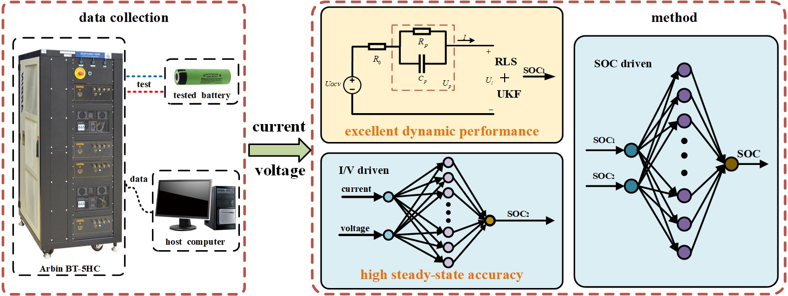
  • This paper proposes a novel framework for a parallel estimation of the SOC that combines UKF and LSTM methods and achieves an accurate estimation through a secondary estimation, which effectively combines the robustness of the model-based method with the accuracy of the data-driven method.
  • In this method, the ECM adopted fixed parameters, which avoids frequent changes in model parameters, and effectively reduces the amount of calculation.
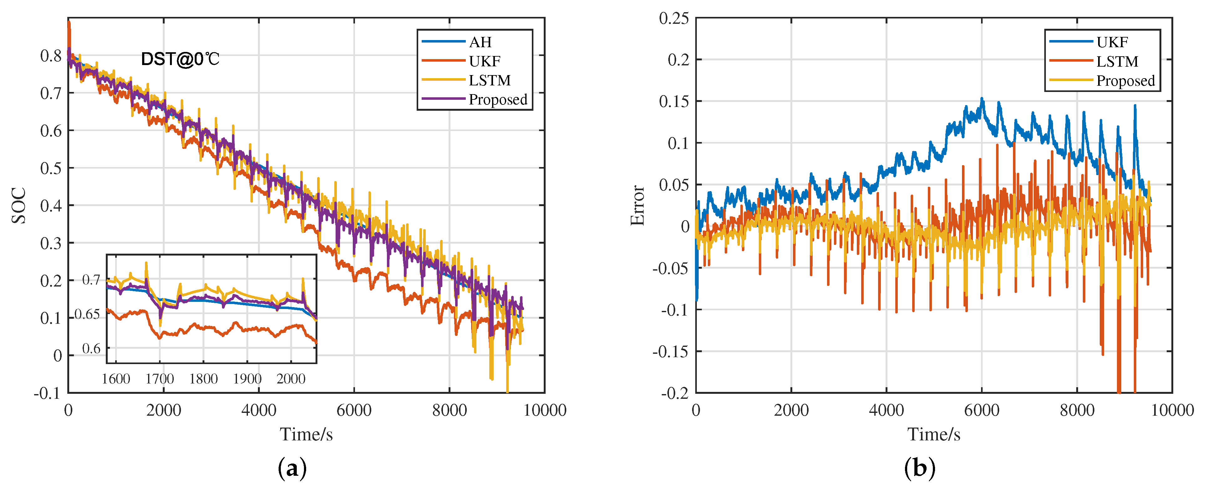
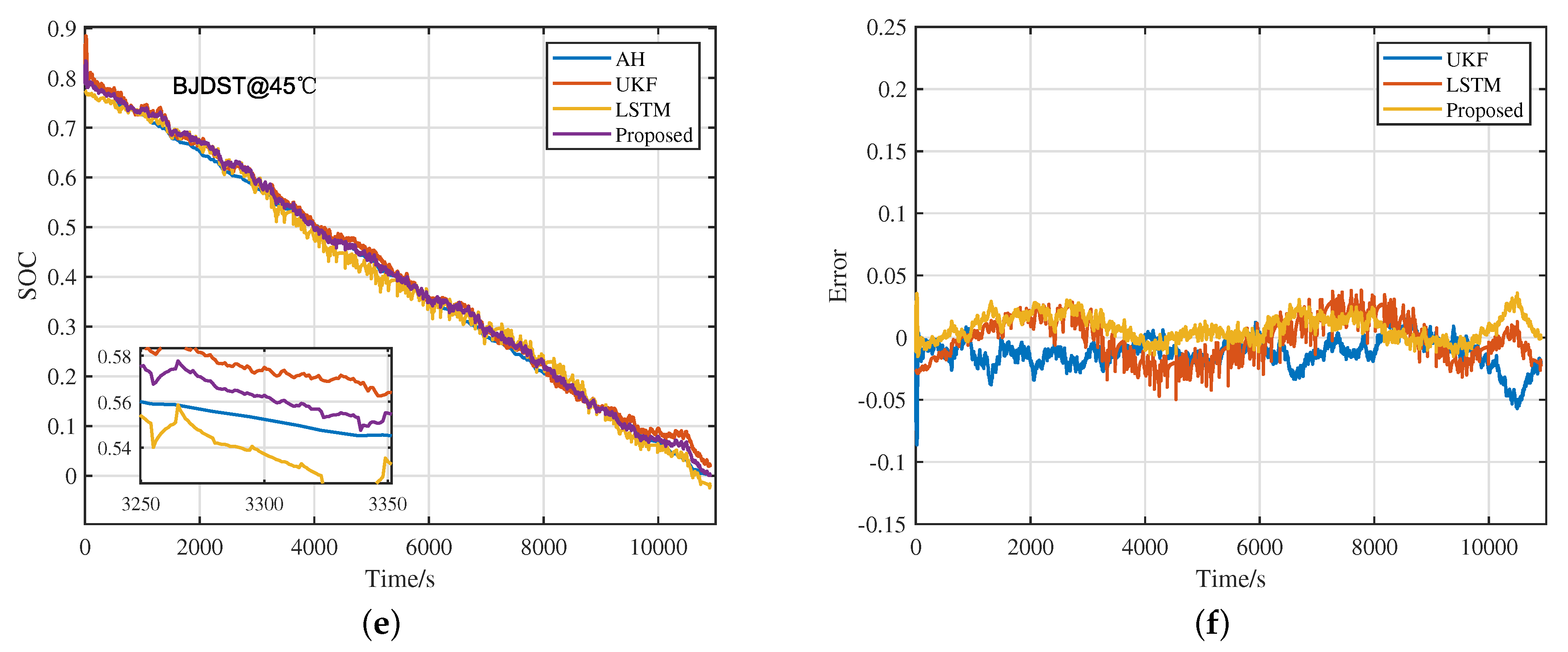
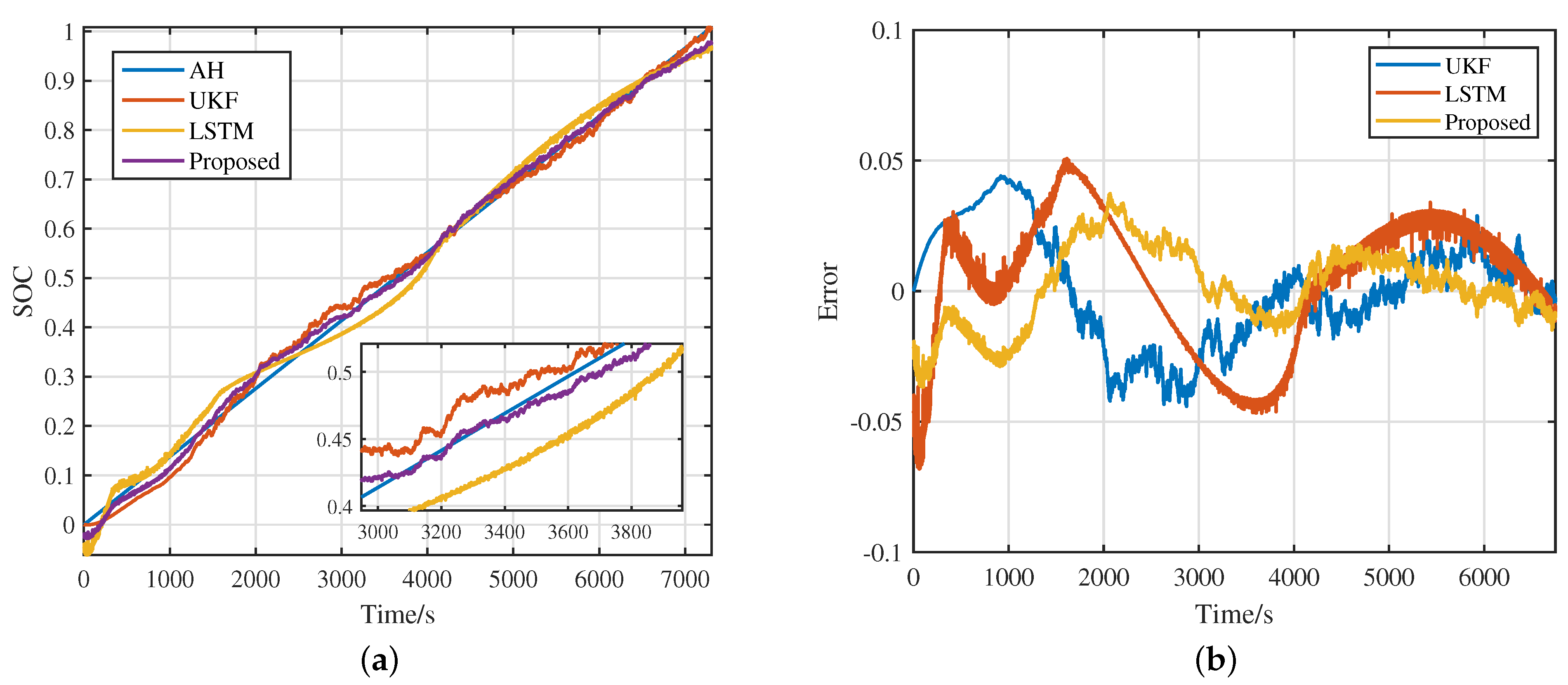
  • Experiments are carried out at 0 °C, 25 °C and 45 °C under DST, BJDST, and FUDS conditions, and verified on different kinds of batteries and charging data, which proves the accuracy, robustness, and universality of the proposed method.
The remainder of this paper is divided into the following parts. Section 2 introduces the equivalent model and theoretical knowledge of LSTM used in the proposed method and the framework of the proposed method. Section 3 describes the experiment process and analyzes the estimation results achieved under DST conditions. Section 4 verifies and discusses the proposed method. Section 5 provides a conclusion.

2. Theoretical Knowledge of the Proposed Method
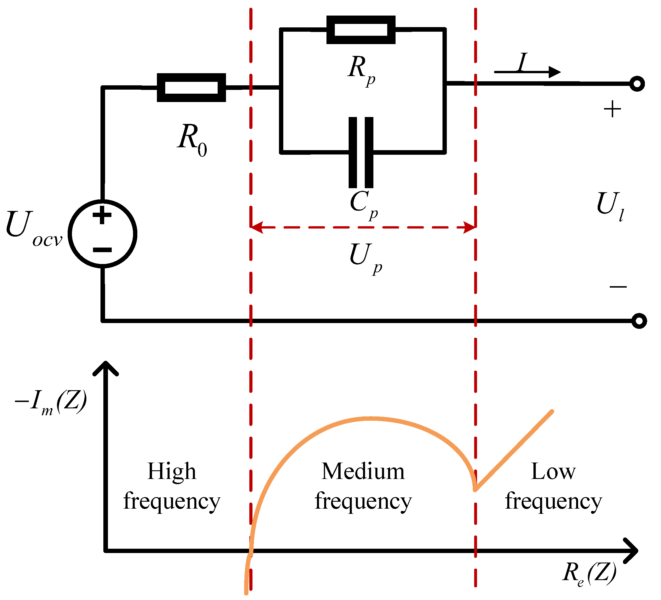
2.1. Battery Model

The ECM is a popular choice due to its straightforward physical interpretation, simple structure, and high practicality. Hu et al. [36] conducted a comprehensive investigation of twelve battery models, revealing that complex models do not necessarily outperform simple yet accurate models in real-world applications. In this paper, we focus on the first-order RC model, which is depicted in Figure 1. The first-order RC model corresponds to the semi-circle of the middle-frequency part of the Nyquist plot of the battery, and the intersection of the low-frequency part with the real axis is the sum of the polarization resistance and the ohmic internal resistance, while the intersection of the high-frequency part with the real axis is the value of the ohmic internal resistance.
Where  U o c v  is OCV; this exhibits a clear functional relationship with SOC.  U l  is terminal voltage, which can be obtained by measurement.  U p  is polarization voltage.  R 0 R p , and  C p  denote the ohmic internal resistance, polarization resistance, and polarization capacitance, respectively. I is the battery current and consider the discharge to be positive.
According to Kirchhoff’s law, the circuit equation of the first-order RC model can be expressed as:
d U p d t = 1 R p C p U p + 1 C p I U l = U o c v U p R 0 I
The AH method is a widely used approach for calculating the reference SOC, which represents the change in electrical quantity resulting from the integral of the current over time. SOC can be determined using the following equation:
S O C t = S O C 0 1 C N η I d t
where  S O C t  and  S O C 0  present an SOC value at time t and initial time,  η  is Coulomb efficiency, and  C N  is battery capacity.
The state space equation after discretization is as follows:
S O C ( k ) U p ( k ) = 1 0 0 e Δ t R p C p S O C ( k 1 ) U p ( k 1 ) + η Δ t C N R p ( 1 e Δ t R p C p ) I ( k 1 ) U l ( k ) = U o c v ( k ) I ( k ) R 0 U p ( k )
where  Δ t  is the sampling interval.

2.1.1. Parameter Identification Method

This paper uses the recursive least squares (RLS) method to perform the parameter identification. The least squares (LS) method is a common mathematical optimization technique, used to obtain the parameter estimates of the system by minimizing the sum of the squares of errors between the observed data and the estimated values, which is widely used in system parameter identification because of its simple principle, easy implementation, and fast convergence speed. Its recursive form is often used in the online parameter identification of lithium–ion battery models. Consider the following expression:
d ( k ) = φ ( k ) θ ( k ) + e ( k )
where  d ( k )  is the output variable,  φ ( k )  is input variable matrix,  θ ( k )  is parameter vector,  e ( k )  is white noise. For LS, the sum of squares of prediction errors is defined as the cost function:
J ( θ ( k ) ) = i = 1 k [ Δ d ( k ) ] 2 = i = 1 k [ d ( k ) φ ( k ) θ ^ ( k ) ] 2
where  Δ d ( k )  is the prediction error,  θ ^ ( k )  is the estimation of  θ ( k ) . By minimizing the cost function  J ( θ ( k ) ) θ ^ ( k )  can be obtained as
θ ^ ( k ) = [ Φ T ( k ) Φ ( k ) ] 1 Φ T ( k ) D ( k )
where  Φ ( k ) = [ φ T ( 1 ) , φ T ( 2 ) , , φ T ( k ) ] T D ( k ) = [ d ( 1 ) , d ( 2 ) , , d ( k ) ] T . Then, the RLS can be obtained:
K ( k ) = P ( k 1 ) φ T ( k ) [ 1 + φ ( k ) P ( k 1 ) φ T ( k ) ] 1 θ ^ ( k ) = θ ^ ( k 1 ) + K ( k ) [ d ( k ) φ ( k ) θ ^ ( k 1 ) ] P ( k ) = P ( k 1 ) K ( k ) φ ( k ) P ( k 1 )
where  K ( k )  is the gain matrix and  P ( k )  is the covariance matrix.
Before using the RLS method, transform the battery model into the following least-squares formula:
U o c v U l = I ( R 0 + 1 1 + R p C p s R p )
Use the bilinear transformation method discribed in the above formula and convert it to the time domain.
U o c v ( z ) U l ( z ) I ( z ) = a 1 + a 2 z 1 1 + a 3 z 1
U o c v ( k ) U l ( k ) = a 3 ( U o c v ( k 1 ) U l ( k 1 ) ) + a 1 I ( k ) + a 2 I ( k 1 )
a 1 = R 0 T + R p T + 2 R 0 R p C p T + 2 R p C p a 2 = R 0 T + R p T 2 R 0 R p C p T + 2 R p C p a 3 = T 2 R p C p T + 2 R p C p
where T is the sampling time.
Through the above transformation,  d ( k ) θ ( k )  and  φ ( k )  in Equation (12) are shown as follows:
d ( k ) = U o c v ( k ) U l ( k ) θ ( k ) = [ a 1 ; a 2 ; a 3 ] φ ( k ) = [ I ( k ) , I ( k 1 ) , d ( k 1 ) ]

2.1.2. Model-Based SOC Estimation Method

The state estimation of lithium–ion batteries is a complex nonlinear problem. In contrast to the traditional KF, the UKF employs the unscented transformation (UT) to address the nonlinearities in SOC estimation [37]. This paper uses the first-order RC model as the basis of the UKF method to estimate SOC. The first step in the UKF method is to perform the UT. This involves assuming that the nonlinear relationship between the state variable x and its observation variable y is expressed by  y = f ( x ) . The UT steps for the nonlinear system are as follows.
  • Symmetric sampling:
    x i = x ^ , i = 0 ,
    x i = x ^ + ( ( n + λ ) P ) i , i = 1 , 2 , 3 . . . , n ,
    x i = x ^ ( ( n + λ ) P ) i n , i = n + 1 , n + 2 , . . . , 2 n .
  • Calculate the corresponding weight of sigma points:
    ω m 0 = λ n + λ ,
    ω c 0 = λ n + λ + ( 1 α 2 + β ) ,
    ω m i = ω c i = λ 2 ( n + λ ) , i = 1 , 2 , . . . , 2 n .
  • Calculate the mean and covariance of  y = f ( x ) :
    y ^ = i = 0 2 n ω m i f ( x i ) ,
    P y = i = 0 2 n ω c i [ f ( x i ) y ^ ] [ f ( x i ) y ^ ] T .
where  x ^  and P are the mean and covariance of n-dimensional state variable,  β  is a positive number,  α  generally requires a number between 0.01 and 1,  λ  is the scaling factor, which satisfies  λ = α 2 ( n + k ) n k = 3 n . In application, to ensure the semi-positive nature of the covariance, k is often taken as 0.
Considering the impact of noise, Equation (3) can be written in the following form:
x ( k ) = f ( x ( k 1 ) , u ( k 1 ) ) + w ( k 1 ) y ( k ) = h ( x ( k ) , u ( k ) ) + v ( k )
where f and h are corresponding nonlinear functions,  u ( k )  is input, and  w ( k ) , and  v ( k )  present process noise and measurement noise, respectively. Assuming they are Gaussian white noise, and their covariance is  Q w  and  R v , Equations (3) and (13) show that  x ( k ) = S O C ( k ) U p ( k )  and  y ( k ) = U l ( k ) .
The application process of the UKF method on the first-order RC model is shown in Figure 2. First, obtain the sigma points, then predict the state variables using the sampling points, and calculate the variance matrix. Then, update sigma points, predict the measured values and calculate the variance matrix of the measured values, and calculate the covariance matrix of the state variable and the measurement values. Finally, update each parameter. The specific steps are as follows:
  • Obtain  2 n + 1  sigma points ( x k i , i = 1 , 2 , . . . , 2 n + 1 ) through UT; calculate the predicted value of the state variable:  x k + 1 | k i = f ( x k i , u k ) .
  • Mean value of the predicted value of state variable:  x ^ k + 1 | k = i = 0 2 n ω m i x k + 1 | k i .
  • Variance in state-predicted value:  P x , k + 1 | k = i = 0 2 n ω c i ( x k + 1 | k i x ^ k + 1 | k ) ( x k + 1 | k i x ^ k + 1 | k ) T + Q k + 1 .
  • Update the sampling points and calculate the observation prediction value:  y k + 1 | k i = h ( x k + 1 | k i , u k + 1 ) .
  • Mean value of observed predicted value:  y ^ k + 1 | k = i = 0 2 n ω m i y k + 1 | k i .
  • Variance in observed predicted value:  P y , k + 1 = i = 0 2 n ω c i ( y k + 1 | k i y ^ k + 1 | k ) ( y k + 1 | k i y ^ k + 1 | k ) T + R k + 1 .
  • Covariance of state variable and observation:  P x y , k + 1 = i = 0 2 n ω c i ( x k + 1 | k i x ^ k + 1 | k ) ( y k + 1 | k i y ^ k + 1 | k ) T .
  • Update Kalman filter gain:  K k + 1 = P x y , k + 1 P y , k + 1 .
  • Update status variables:  x ^ k + 1 | k + 1 = x ^ k + 1 | k + K k + 1 ( y k + 1 y ^ k + 1 | k ) .
  • Update covariance of state variables:  P x , k + 1 | k + 1 = P x , k + 1 | k K k + 1 P y , k + 1 K k + 1 T .

2.2. Data-Driven SOC Estimation Method

LSTM has gained widespread popularity due to its ability to overcome the issue of gradient explosion or vanishing in recurrent neural networks (RNNs) [38]. Differing from the single network structure of RNN, LSTM achieves data updates and forgetting through three gates, thereby resolving the problem of long-term dependence. These gates include the forgetting gate, controlled by the sigmoid function, the input gate, controlled by both the sigmoid and the hyperbolic tangent function, and the output gate, determined by the sigmoid function and subsequently processed by the hyperbolic tangent function. At time t, the cell state at the previous moment  c t 1 , the LSTM output value at the previous moment  h t 1 , and the current moment input  x t  are input to LSTM. The forget gate outputs a value between 0 and 1 via the sigmoid function, which determines how much of  c t 1  is retained at  c t , the input gate determines how much of the input is saved to  c t , and the output gate controls how much of  c t  is output to  h t . The LSTM unit structure and the processing flow of the LSTM algorithm are shown in Figure 3 and Equation (14), respectively.
i t = σ ( W x i x t + W h i h t 1 + b i ) , f t = σ ( W x f x t + W h f h t 1 + b f ) , c t = f t c t 1 + i t t a n h ( W x c x t + W h c h t 1 + b c ) , o t = σ ( W x o x t + W h o h t 1 + b o ) , h t = o t t a n h ( c t ) ,
where  i t f t c t o t , and  h t  represent the input gate output, forgetting gate output, current state, output gate output, and hidden layer state, respectively.  σ  and tanh represent the sigmoid function and the hyperbolic tangent function, W represents the weight matrix, and b is the offset vector.

2.3. The Method Framework

A novel parallel SOC estimation method that combines UKF and LSTM is proposed in this paper, which can be divided into two parts. The first part includes the UKF estimation method based on the first-order RC model and LSTM estimation method, and the second part includes one LSTM network. To reduce the calculation amount of the proposed method and make it applicable to the actual management system, the first-order RC model parameters are fixed to avoid constant calculations and changes in model parameters. The voltage and current under different working conditions enter the first part and are filtered by UKF to obtain a stable SOC estimate. At the same time, an accurate SOC estimate is obtained through the LSTM network. Then, the two estimated results are input into the second part and the second LSTM network is used for secondary estimation. There are errors between the two SOC estimates and the reference SOC values in the first part because the model and input data do not meet the premise of the model-based method and the data-driven method, especially when the input data greatly differ from the data set used for training. When the results obtained in the first part are estimated by the second LSTM, the advantages of the two methods are effectively integrated. The estimated value of UKF can effectively improve the volatility of the estimated value of LSTM, and the accuracy of the estimated value of LSTM makes up for the problem of a large deviation in the estimated value of the UKF method. The structure block diagram of the proposed method is illustrated in Figure 4.

3. Experiment

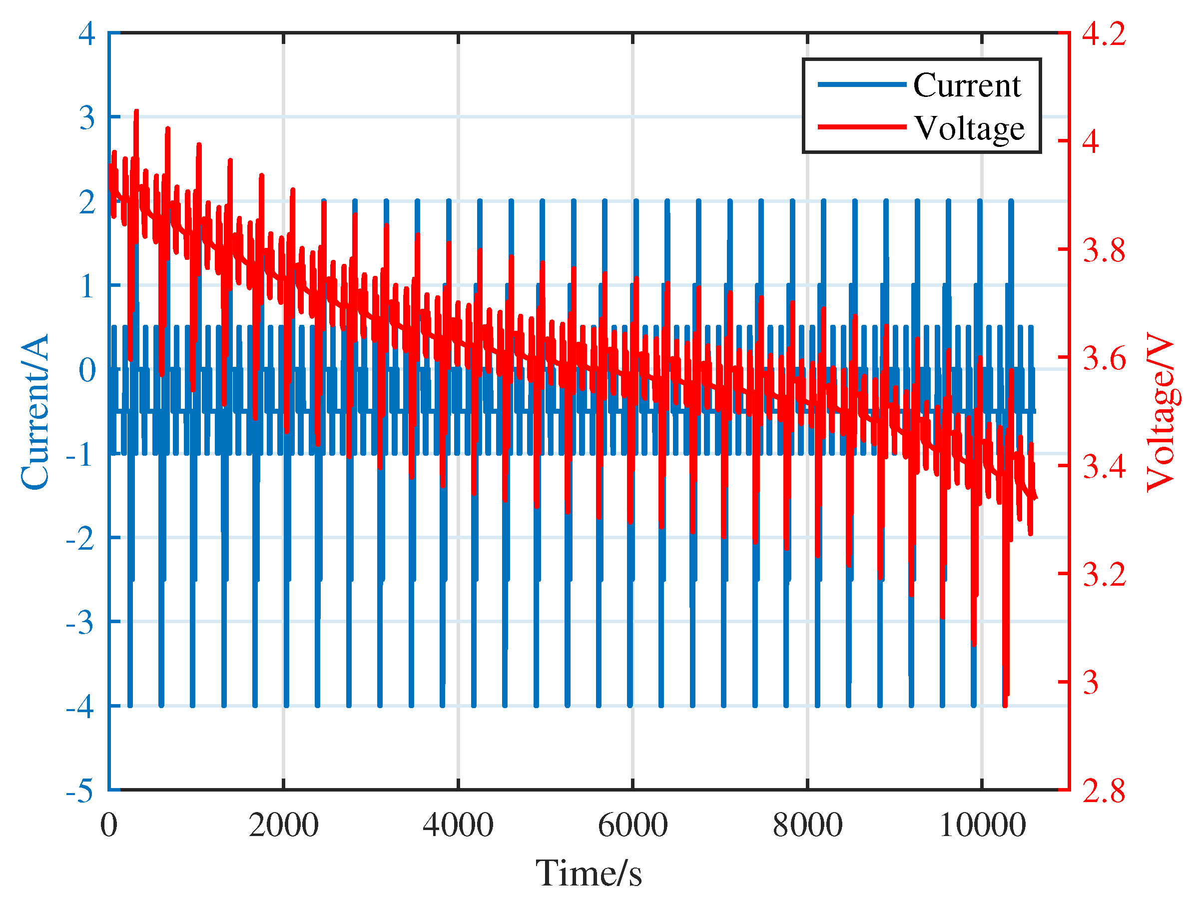
3.1. Experimental Platform and Data

This study uses the INR-18650-20R battery as the subject of investigation and the specifications of the tested batteries are displayed in Table 1, which undergoes charging and discharging procedures using the Arbin battery testing equipment. The experimental process comprises an OCV test and dynamic test, wherein the voltage, current, and temperature are meticulously recorded. During the experiment, the external environment is regulated by the thermal chamber.
The DST working condition data are utilized as the training and verification set for the proposed method. The OCV test at 25 °C is used to obtain the data. Firstly, charge the battery to 4.2 V. Then, discharge the battery to 2.5 V with 1A pulse current, and measure the terminal voltage after resting the battery for two hours at 10% SOC per discharge. Finally, recharge the battery to the cutoff voltage of 4.2 V, and record the terminal voltage as described in the previous step. The OCV corresponding to SOC can be obtained by averaging the terminal voltage of charge and discharge. Then, using the obtained SOC-OCV data and polynomial fitting method, the functional relationship between SOC and OCV is determined as:
U o c v = 7.708 S O C 6 18.26 S O C 5 + 9.985 S O C 4 + 6.409 S O C 3 7.569 S O C 2 + 2.636 S O C + 3.271
Parameters of the first-order RC model are identified under the DST working condition of 25 °C, and the current and voltage of the DST working condition are shown in Figure 5.
In this paper, the average values of the results based on the RLS method are used as the parameters of the first-order RC model, and the results are shown in Table 2.

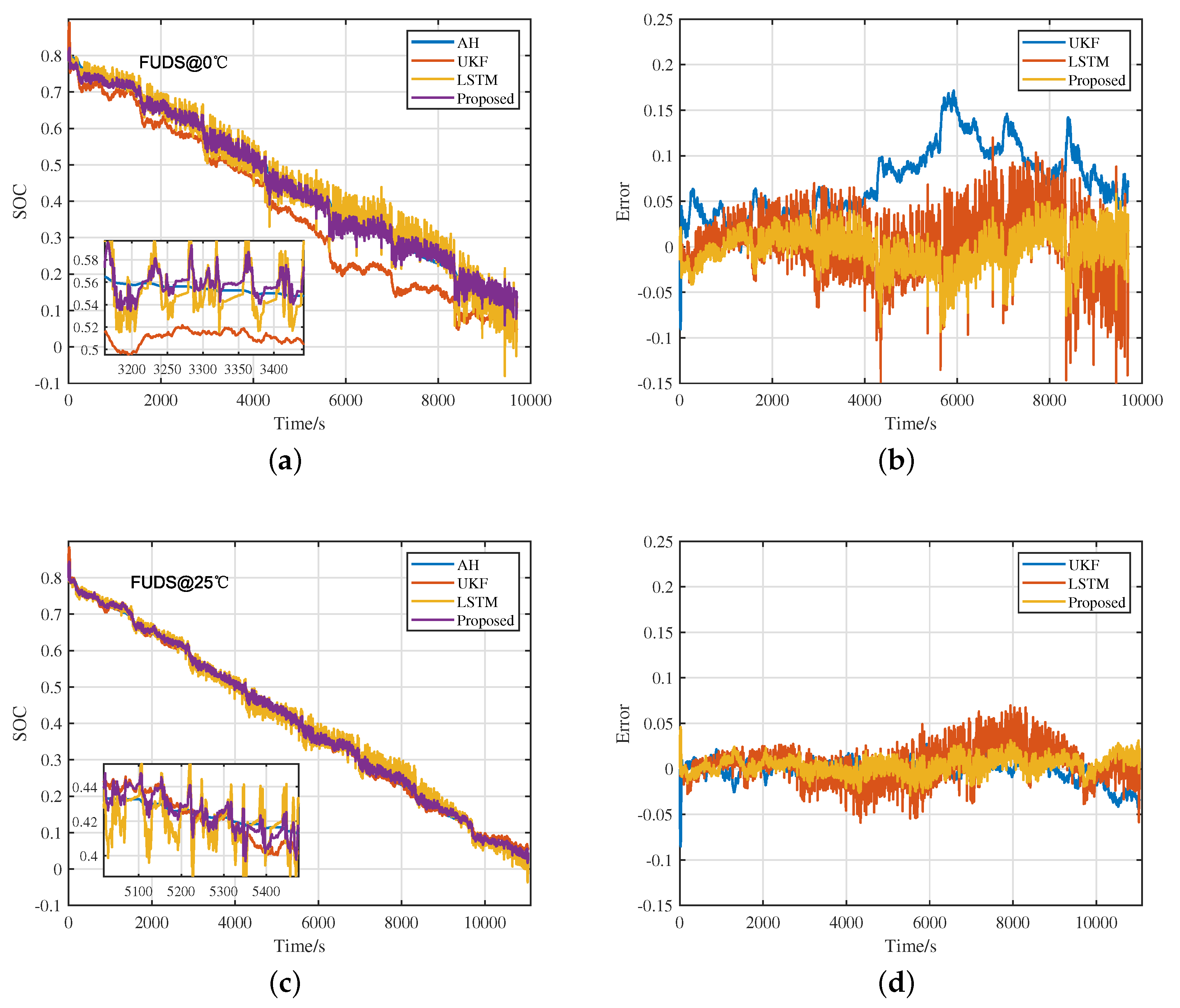
3.2. Experiment Results and Analysis

The first LSTM network architecture consists of two input variables, two LSTM layers, and one output. The second LSTM network architecture consists of two input variables, a single LSTM layer, and an output. The output of the second LSTM network is the final SOC estimate. Figure 6 shows the results of using UKF and LSTM to estimate SOC separately and jointly under DST conditions. This experiment also referred to the experimental data of the CALCE battery group and estimated from  S O C = 0.8 .
To evaluate the performance of the proposed method, the mean absolute error (MAE) and RMSE are utilized as evaluation metrics, where  y i  is calculated based on the AH method, and  y ^ i  is the estimated value. The formula is as follows:
M A E = i = 1 n | y i y ^ i | n
R M S E = i = 1 n ( y i y ^ i ) 2 n
Table 3 shows the estimated results of the three methods under DST conditions at three temperatures. In the data-driven part of the method, 70% of the data are used as the training set, and 30% are used for verification. Figure 6 and Table 3 show that the first-order RC model with fixed parameters estimated by UKF performs well at room temperature (25 °C), with an RMSE of only 1.22%, while the MAE is only 0.93%. At the temperature of 45 °C, the RMSE increases to 1.86%, and the MAE increases to 1.47%. In both cases, the error remains within an acceptable range. When the ambient temperature drops to 0 °C, the shortcomings of the fixed model parameters become apparent, with the RMSE of the estimated result reaching 7.89%, and the MAE reaching 7.02%, which is unacceptable. LSTM performs well in all three temperature environments, with a maximum RMSE of 2.68% and minimum RMSE of 1.55%. However, LSTM estimation results show obvious fluctuations and mutations, because both the data quality and the parameter setting have an impact on the algorithm. The data-driven method is mainly used to extract data features for fitting, which easily leads to overfitting. To achieve the ideal estimation effect, it is necessary to design a suitable hyperparameter of LSTM, while there is no systematic strategy for parameter setting. This also illustrates the obvious shortcomings of using only LSTM to estimate SOC. In contrast, the proposed method achieves relatively accurate SOC estimation in all three environments. At room temperature, the RMSE is only 1.06% and the MAE is 0.8%. At extreme temperatures (0 °C), the RMSE is 2.26% and the MAE is 2.08%. As can be seen from the purple curve in Figure 6a,c,e, this method effectively improves the result mutation problem, because the SOC estimated by UKF is stable, while the SOC estimated by LSTM is of high accuracy. The data-driven method is used again to extract the characteristics of the two SOC estimates for further estimation, presenting an accurate and stable SOC estimate. Through the above analysis, it can be seen that the accuracy and stability of SOC estimated using only UKF or LSTM cannot be guaranteed at the three temperatures. However, the proposed method can achieve accurate and stable output estimates at the three temperatures under DST conditions.

4. Verification and Discussion

The LSTM network requires the input data to be normalized; thus, the data are first standardized using the maximum and minimum values of the original data and processed to a range of 0–1, and the conversion function is as follows:
X = x x m i n x m a x x m i n

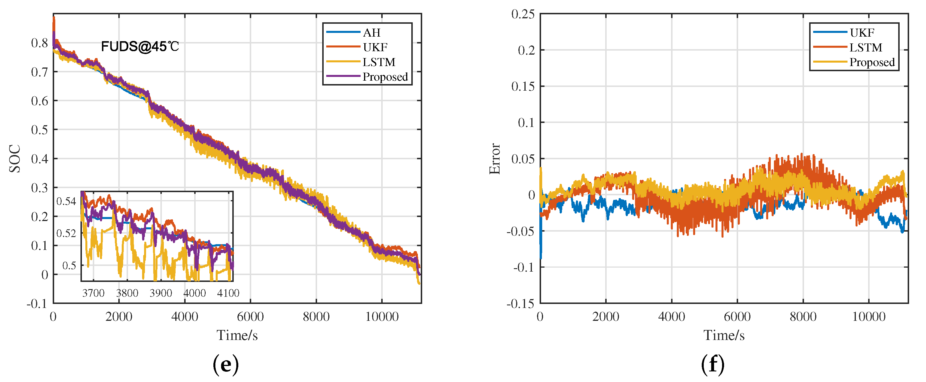
4.1. Verify under Different Working Conditions

To evaluate the performance of the proposed method under different working conditions, it is tested at three temperatures under BJDST and FUDS conditions. The SOC estimation results under BJDST and FUDS at three temperatures are shown in Figure 7 and Figure 8, and Table 4, respectively. It can be seen from Table 4 that the maximum RMSE and maximum MAE of SOC estimated by the UKF method for the first-order RC model based on fixed parameters are only 1.72% and 1.37% at 25 °C and 45 °C. From Table 3 and Table 4, the result shows that only the model-based method is used to estimate SOC in the temperature range above 25 °C. However, when the temperature drops to 0 °C, the maximum RMSE of UKF reaches 8.98%, which is larger than that under DST conditions. This indicates that the first-order RC model with fixed parameters cannot be used under extreme temperature (0 °C) conditions and does not apply to different conditions. An LSTM network trained in DST conditions also performs well in BJDST and FUDS conditions, with a maximum RMSE of 3.23% and an MAE of 2.26%. From the error curves of the single LSTM at three temperatures in Figure 7 and Figure 8, the LSTM estimates in different working conditions are accurate, but the mutation situation becomes more obvious, which does not apply to the actual management system. In the proposed method, under BJDST and FUDS conditions, the maximum RMSE is only 2.24%, and the maximum MAE is 1.75%, both of which occur at extreme temperatures. Compared with the minimum RMSE and minimum MAE estimated by UKF and LSTM methods at the same temperature, the accuracy is improved by 21.7% and 19.4%, respectively. At room temperature, the maximum RMSE of the proposed method is 1.04%, and the maximum MAE is only 0.83%. Compared with the UKF method under the same conditions, the accuracy of the proposed method is increased by nearly 18.1%, and with the LSTM method under the same conditions, the accuracy of the proposed method is increased by nearly 45.3%. As can be seen from the error curve, the mutation of the method is reduced and the overall is relatively stable. This result is consistent with the results obtained under the DST condition, confirming the accuracy and robustness of the proposed method.

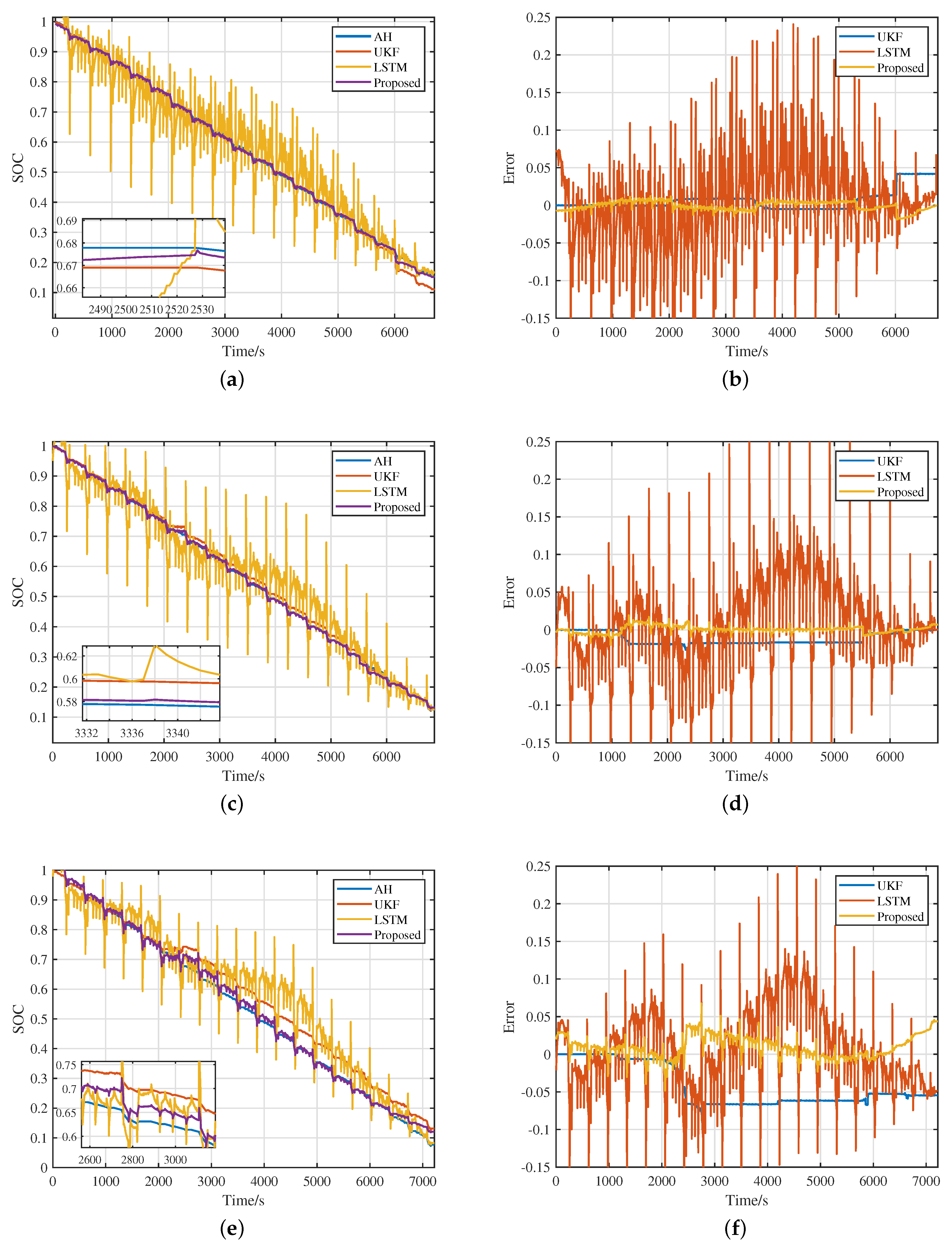
4.2. Verify Universality

To verify the universality of the proposed method, it was applied to an A123 battery; a detailed description is shown in Table 5. The DST working condition data of the A123 battery at three different temperatures were used to build and test the model, using data from the CALCE battery group. The estimation results are shown in Figure 9.
The superiority of this method is more prominent in the A123 battery. At room temperature, UKF performs well, with an RMSE of 1.4%, but the proposed method has a higher estimation accuracy, with an RMSE of only 0.36%. As the temperature develops towards both ends, the estimated results of a single UKF or single LSTM change in a worse direction, and the fluctuation change in the single LSTM is more obvious. This phenomenon is a combination of data quality and hyperparameter settings. The method proposed in this paper can help to resolve this problem; when the temperature drops to 0 °C, the parallel estimation method has an RMSE of only 0.77%. The above analysis proves that the method proposed in this paper is also applicable to other types of batteries, and even obtains a higher accuracy due to the different characteristics of the batteries themselves.
All the above estimations were carried out under discharge conditions. To prove that the method is also applicable in the charging process, estimations were carried out on the charging data of the INR-18650-20R battery. The estimation data were selected from the low-current OCV charging data of the CALCE battery group at 25 °C, and the estimation results are shown in Figure 10.
The low-current OCV test is based on a constant current charging at 0.1A current until the cut-off voltage is reached. The data in this process are stable, and the artificially added Gaussian white noise has little influence on the estimation results. Therefore, both UKF and LSTM have a good estimation accuracy in this process, as is clear from the estimation results. The proposed method further improves the accuracy of SOC estimations.

5. Conclusions

This paper proposed a novel method that combines model-based and data-driven methods in parallel to estimate the SOC. The framework of this method can be divided into two parts: the first part was composed of UKF and LSTM, in which the first-order RC model with fixed parameters was used as the basis for UKF estimation and parameter identification was realized by RLS, and the second part was composed of an LSTM. The second part was used to achieve accurate SOC estimation. From the results of the estimation, it can be seen that the SOC cannot be accurately estimated using only using the UKF or LSTM under different working conditions and temperatures. However, combining the first parallel estimation and second estimation could achieve an accurate estimation under three different conditions and three different temperatures, and the RMSE was controlled within 2.3% at 0 °C, 25 °C, and 45 °C, and within 1.4% at 25 °C and 45 °C. This method effectively mitigated the limitations associated with each method, thereby enhancing overall estimation performance, especially at extreme temperatures (0 °C). Through the validation of the A123 battery and charging data, the accuracy, robustness, and universality of the proposed method were demonstrated. At the same time, this method simplified the calculation and did not require model accuracy. Through simulation on MATLAB R2022b, it can be seen that it takes less than one millisecond is needed to update SOC with a single UKF, single LSTM, and the method proposed in this paper. Compared with a single estimation method, the proposed method improves the estimation accuracy, but the operating cost is close to that of a single LSTM, which fully satisfies the requirements of an update to the online battery management system. In the future, we will work to improve the accuracy of this method.

Author Contributions

Conceptualization, Y.Z., Y.L. and T.Y.; methodology, Y.Z. and Y.L.; software, Y.Z. and T.Y.; validation, Y.Z.; formal analysis, Y.Z.; investigation, Y.Z.; resources, Y.Z. and Y.L.; data curation, Y.Z. and T.Y.; writing—original draft preparation, Y.Z.; writing—review and editing, Y.L. and T.Y.; supervision, Y.L.; project administration, Y.L.; funding acquisition, Y.L. All authors have read and agreed to the published version of the manuscript.

Funding

This work was supported by the National Natural Science Foundation of China U22A20245 and 61973193.

Data Availability Statement

The data that support the findings of this study are available from the corresponding author upon reasonable request.

Acknowledgments

The authors would like to thank Li Yan for his guidance and help.

Conflicts of Interest

The authors declare no conflict of interest.

Abbreviations

The following abbreviations are used in this manuscript:
AHAmpere-hour counting
BJDSTBeijing dynamic stress test
DSTDynamic stress test
ECMEquivalent circuit model
EKFExtended Kalman filter
FUDSFederal urban driving schedule
KFKalman filter
LSLeast square
LSTMLong short-term memory
MAEMean absolute error
MHLSTMMulti-hidden layer long short-term memory
OCVOpen circuit voltage
RLSRecursive least squares
RMSERoot mean square error
RNNRecurrent neural network
SFEKFSuboptimal fading extended Kalman filtering
SOCState of charge
UKFUnscented Kalman filter
UTUnscented transformation

References

  1. Du, X.; Meng, J.; Peng, J. Hybrid Pseudorandom Sequence for Broadband Impedance Measurements of Lithium-Ion Batteries. IEEE Trans. Ind. Electron. 2023, 70, 6856–6864. [Google Scholar] [CrossRef]
  2. Semeraro, C.; Caggiano, M.; Olabi, A.G.; Dassisti, M. Battery monitoring and prognostics optimization techniques: Challenges and opportunities. Energy 2022, 255, 124538. [Google Scholar] [CrossRef]
  3. Zhao, X.; Qian, X.; Xuan, D.; Jung, S. State of charge estimation of lithium-ion battery based on multi-input extreme learning machine using online model parameter identification. J. Energy Storage 2022, 56, 105796. [Google Scholar] [CrossRef]
  4. Takyi-Aninakwa, P.; Wang, S.; Zhang, H.; Yang, X.; Fernandez, C. A hybrid probabilistic correction model for the state of charge estimation of lithium-ion batteries considering dynamic currents and temperatures. Energy 2023, 273, 127231. [Google Scholar] [CrossRef]
  5. Gong, Z.; Kachura, A.; Assadi, S.A.; Cusimano, N.; Piruzza, J.; Xu, J.; Trescases, O. An EV-Scale Demonstration of In-Situ Battery Electrochemical Impedance Spectroscopy and BMS-Limited Pack Performance Analysis. IEEE Trans. Ind. Electron. 2023, 70, 9112–9122. [Google Scholar] [CrossRef]
  6. Sun, Y.; Li, Y.; Yu, M.; Zhou, Z.; Zhang, Q.; Duan, B.; Shang, Y.; Zhang, C. Variable fractional order - A comprehensive evaluation indicator of lithium-ion batteries. J. Power Sources 2020, 448, 227411. [Google Scholar] [CrossRef]
  7. Shrivastava, P.; Naidu, P.A.; Sharma, S.; Panigrahi, B.K.; Garg, A. Review on technological advancement of lithium-ion battery states estimation methods for electric vehicle applications. J. Energy Storage 2023, 64, 107159. [Google Scholar] [CrossRef]
  8. Xiao, R.; Hu, Y.; Zhang, W.; Chen, Z. A novel approach to estimate the state of charge for lithium-ion battery under different temperatures incorporating open circuit voltage online identification. J. Energy Storage 2023, 67, 107509. [Google Scholar] [CrossRef]
  9. Shrivastava, P.; Soon, T.K.; Idris, M.Y.I.B.; Mekhilef, S.; Adnan, S.B.R.S. Comprehensive co-estimation of lithium-ion battery state of charge, state of energy, state of power, maximum available capacity, and maximum available energy. J. Energy Storage 2022, 56, 106049. [Google Scholar] [CrossRef]
  10. Luan, Z.; Qin, Y.; Hu, B.; Zhao, W.; Wang, C. Estimation of state of charge for hybrid unmanned aerial vehicle Li-ion power battery for considering rapid temperature change. J. Energy Storage 2023, 59, 106479. [Google Scholar] [CrossRef]
  11. Li, S.; Li, Y.; Zhao, D.; Zhang, C. Adaptive state of charge estimation for lithium-ion batteries based on implementable fractional-order technology. J. Energy Storage 2020, 32, 101838. [Google Scholar] [CrossRef]
  12. Wu, C.; Hu, W.; Meng, J.; Xu, X.; Huang, X.; Cai, L. State-of-charge estimation of lithium-ion batteries based on MCC-AEKF in non-Gaussian noise environment. Energy 2023, 274, 127316. [Google Scholar] [CrossRef]
  13. Zhou, W.; Zheng, Y.; Pan, Z.; Lu, Q. Review on the Battery Model and SOC Estimation Method. Processes 2021, 9, 1685. [Google Scholar] [CrossRef]
  14. Wu, S.; Pan, W.; Zhu, M. A Collaborative Estimation Scheme for Lithium-Ion Battery State of Charge and State of Health Based on Electrochemical Model. J. Electrochem. Soc. 2022, 169, 090516. [Google Scholar] [CrossRef]
  15. Li, N.; Zhang, Y.; He, F.; Zhu, L.; Zhang, X.; Ma, Y.; Wang, S. Review of lithium-ion battery state of charge estimation. Glob. Energy Interconnect. 2021, 4, 619–630. [Google Scholar] [CrossRef]
  16. Lian, G.; Ye, M.; Wang, Q.; Wei, M.; Ma, Y. Noise-immune state of charge estimation for lithium-ion batteries based on optimized dynamic model and improved adaptive unscented Kalman filter under wide temperature range. J. Energy Storage 2023, 64, 107223. [Google Scholar] [CrossRef]
  17. Hou, J.; Liu, J.; Chen, F.; Li, P.; Zhang, T.; Jiang, J.; Chen, X. Robust lithium-ion state-of-charge and battery parameters joint estimation based on an enhanced adaptive unscented Kalman filter. Energy 2023, 271, 126998. [Google Scholar] [CrossRef]
  18. Yu, M.; Li, Y.; Podlubny, I.; Gong, F.; Sun, Y.; Zhang, Q.; Shang, Y.; Duan, B.; Zhang, C. Fractional-order modeling of lithium-ion batteries using additive noise assisted modeling and correlative information criterion. J. Adv. Res. 2020, 25, 49–56. [Google Scholar] [CrossRef]
  19. Wang, M.; Wang, G.; Xiao, Z.; Sun, Y.; Zheng, Y. State of Charge Estimation of LiFePO4 in Various Temperature Scenarios. Batteries 2023, 9, 43. [Google Scholar] [CrossRef]
  20. Ragone, M.; Yurkiv, V.; Ramasubramanian, A.; Kashir, B.; Mashayek, F. Data driven estimation of electric vehicle battery state-of-charge informed by automotive simulations and multi-physics modeling. J. Power Sources 2021, 483, 229108. [Google Scholar] [CrossRef]
  21. Ma, L.; Zhang, T. Deep learning-based battery state of charge estimation: Enhancing estimation performance with unlabelled training samples. J. Energy Chem. 2023, 80, 48–57. [Google Scholar] [CrossRef]
  22. Hao, X.; Wang, S.; Fan, Y.; Xie, Y.; Fernandez, C. An improved forgetting factor recursive least square and unscented particle filtering algorithm for accurate lithium-ion battery state of charge estimation. J. Energy Storage 2023, 59, 106478. [Google Scholar] [CrossRef]
  23. Wang, C.; Li, Q.; Tang, A.; Zhang, Z. A comparative study of state of charge estimation methods of ultracapacitors for electric vehicles considering temperature characteristics. J. Energy Storage 2023, 63, 106908. [Google Scholar] [CrossRef]
  24. El Fallah, S.; Kharbach, J.; Hammouch, Z.; Rezzouk, A.; Ouazzani Jamil, M. State of charge estimation of an electric vehicle’s battery using Deep Neural Networks: Simulation and experimental results. J. Energy Storage 2023, 62, 106904. [Google Scholar] [CrossRef]
  25. Liu, X.; Li, Q.; Wang, L.; Lin, M.; Wu, J. Data-Driven State of Charge Estimation for Power Battery With Improved Extended Kalman Filter. IEEE Trans. Instrum. Meas. 2023, 72, 1–10. [Google Scholar] [CrossRef]
  26. Wadi, A.; Abdel-Hafez, M.F.; Hussein, A.A.; Alkhawaja, F. Alleviating Dynamic Model Uncertainty Effects for Improved Battery SOC Estimation of EVs in Highly Dynamic Environments. IEEE Trans. Veh. Technol. 2021, 70, 6554–6566. [Google Scholar] [CrossRef]
  27. Zhang, X.; Hou, J.; Wang, Z.; Jiang, Y. Study of SOC Estimation by the Ampere-Hour Integral Method with Capacity Correction Based on LSTM. Batteries 2022, 8, 170. [Google Scholar] [CrossRef]
  28. Moulik, B.; Dubey, A.K.; Ali, A.M. A Battery Modeling Technique Based on Fusion of Hybrid and Adaptive Algorithms for Real-Time Applications in Pure EVs. IEEE Trans. Intell. Transp. Syst. 2023, 24, 2760–2771. [Google Scholar] [CrossRef]
  29. Takyi-Aninakwa, P.; Wang, S.; Zhang, H.; Yang, X.; Fernandez, C. An optimized long short-term memory-weighted fading extended Kalman filtering model with wide temperature adaptation for the state of charge estimation of lithium-ion batteries. Appl. Energy 2022, 326, 120043. [Google Scholar] [CrossRef]
  30. Bai, W.; Zhang, X.; Gao, Z.; Xie, S.; Chen, Y.; He, Y.; Zhang, J. State of charge estimation for lithium-ion batteries under varying temperature conditions based on adaptive dual extended Kalman filter. Electr. Power Syst. Res. 2022, 213, 108751. [Google Scholar] [CrossRef]
  31. Liu, X.; Yang, J.; Wang, L.; Wu, J. Bayesian information criterion based data-driven state of charge estimation for lithium-ion battery. J. Energy Storage 2022, 55, 105669. [Google Scholar] [CrossRef]
  32. Xie, Y.; Wang, S.; Zhang, G.; Fan, Y.; Fernandez, C.; Blaabjerg, F. Optimized multi-hidden layer long short-term memory modeling and suboptimal fading extended Kalman filtering strategies for the synthetic state of charge estimation of lithium-ion batteries. Appl. Energy 2023, 336, 120866. [Google Scholar] [CrossRef]
  33. Xu, S.; Zhou, F.; Liu, Y. A Hybrid Method for Lithium-Ion Batteries State-of-Charge Estimation Based on Gated Recurrent Unit Neural Network and an Adaptive Unscented Kalman Filter. J. Electrochem. Energy Convers. Storage 2022, 19, 031005. [Google Scholar] [CrossRef]
  34. Cui, Z.; Kang, L.; Li, L.; Wang, L.; Wang, K. A combined state-of-charge estimation method for lithium-ion battery using an improved BGRU network and UKF. Energy 2022, 259, 124933. [Google Scholar] [CrossRef]
  35. Cui, X.; Xu, B. State of Charge Estimation of Lithium-Ion Battery Using Robust Kernel Fuzzy Model and Multi-Innovation UKF Algorithm Under Noise. IEEE Trans. Ind. Electron. 2022, 69, 11121–11131. [Google Scholar] [CrossRef]
  36. Hu, X.; Li, S.; Peng, H. A comparative study of equivalent circuit models for Li-ion batteries. J. Power Sources 2012, 198, 359–367. [Google Scholar] [CrossRef]
  37. Hossain, M.; Haque, M.E.; Arif, M.T. Online Model Parameter and State of Charge Estimation of Li-Ion Battery Using Unscented Kalman Filter Considering Effects of Temperatures and C-Rates. IEEE Trans. Energy Convers. 2022, 37, 2498–2511. [Google Scholar] [CrossRef]
  38. Quan, R.; Liu, P.; Li, Z.; Li, Y.; Chang, Y.; Yan, H. A multi-dimensional residual shrinking network combined with a long short-term memory network for state of charge estimation of Li-ion batteries. J. Energy Storage 2023, 57, 106263. [Google Scholar] [CrossRef]
Figure 1. First-order RC model and battery Nyquist plot.
Batteries 09 00358 g001
Figure 2. UKF–one filtering period.
Batteries 09 00358 g002
Figure 3. The internal structure of the LSTM unit.
Batteries 09 00358 g003
Figure 4. Block diagram of the structure of the proposed method.
Batteries 09 00358 g004
Figure 5. The voltage and current at 25 °C in DST condition.
Batteries 09 00358 g005
Figure 6. (a) The SOC estimation results of the AH, UKF, LSTM, and the proposed methods in the DST condition at 0 °C; (b) The estimated error of the UKF, LSTM, and the proposed methods in the DST condition at 0 °C; (c) The SOC estimation results of the AH, UKF, LSTM, and the proposed methods in the DST condition at 25 °C; (d) The estimated error of the UKF, LSTM, and the proposed methods in the DST condition at 25 °C; (e) The SOC estimation results of the AH, UKF, LSTM, and the proposed methods in the DST condition at 45 °C; (f) The estimated error of the UKF, LSTM, and the proposed methods in the DST condition at 45 °C.
Batteries 09 00358 g006aBatteries 09 00358 g006b
Figure 7. (a) The SOC estimation results of the AH, UKF, LSTM, and the proposed methods in the BJDST condition at 0 °C; (b) The estimated error of the UKF, LSTM, and the proposed methods in the BJDST condition at 0 °C; (c) The SOC estimation results of the AH, UKF, LSTM, and the proposed methods in the BJDST condition at 25 °C; (d) The estimated error of the UKF, LSTM, and the proposed methods in the BJDST condition at 25 °C; (e) The SOC estimation results of the AH, UKF, LSTM, and the proposed methods in the BJDST condition at 45 °C; (f) The estimated error of the UKF, LSTM, and the proposed methods in the BJDST condition at 45 °C.
Batteries 09 00358 g007aBatteries 09 00358 g007b
Figure 8. (a) The SOC estimation results of the AH, UKF, LSTM, and the proposed methods in the FUDS condition at 0 °C; (b) The estimated error of the UKF, LSTM, and the proposed methods in the FUDS condition at 0 °C; (c) The SOC estimation results of the AH, UKF, LSTM, and the proposed methods in the FUDS condition at 25 °C; (d) The estimated error of the UKF, LSTM, and the proposed methods in the FUDS condition at 25 °C; (e) The SOC estimation results of the AH, UKF, LSTM, and the proposed methods in the FUDS condition at 45 °C; (f) The estimated error of the UKF, LSTM, and the proposed methods in the FUDS condition at 45 °C.
Batteries 09 00358 g008aBatteries 09 00358 g008b
Figure 9. (a) The SOC estimation results of the AH, UKF, LSTM, and the proposed methods in the DST condition at 0 °C; (b) The estimated error of the UKF, LSTM, and the proposed methods in the DST condition at 0 °C; (c) The SOC estimation results of the AH, UKF, LSTM, and the proposed methods in the DST condition at 25 °C; (d) The estimated error of the UKF, LSTM, and the proposed methods in the DST condition at 25 °C; (e) The SOC estimation results of the AH, UKF, LSTM, and the proposed methods in the DST condition at 40 °C; (f) The estimated error of the UKF, LSTM, and the proposed methods in the DST condition at 40 °C.
Batteries 09 00358 g009
Figure 10. (a) The SOC estimation results for low current charging at 25 °C; (b) The estimated error in the charge condition at 25 °C.
Batteries 09 00358 g010
Table 1. Specifications of lithium-ion battery.
BrandTypeNominal VoltageNominal CapacityCut-Off Voltages
SamsungINR-18650-20R3.6 V2 Ah2.5 V/4.2 V
Table 2. Battery parameter identification results.
ConditionTemperature   R 0 ( Ω )   R 1 ( Ω )   C 1 ( F )
DST25 °C0.07150.0223996.2
Table 3. Estimation results of three methods under DST conditions.
TemperatureDataMethodMAERMSE
DST dataUKF0.07020.0789
Training setLSTM0.01480.0192
0 °C proposed0.01140.0150
Verification setLSTM0.01820.0268
proposed0.02080.0226
DST dataUKF0.00930.0122
Training setLSTM0.01100.0155
25 °C proposed0.00570.0076
Verification setLSTM0.01790.0232
proposed0.00800.0106
DST dataUKF0.01470.0186
Training setLSTM0.01560.0183
45 °C proposed0.00830.0097
Verification setLSTM0.01530.0184
proposed0.01090.0129
Table 4. MAE and RMSE of three methods under different temperatures and working conditions.
ConditionTemperature MAE RMSE
UKFLSTMProposedUKFLSTMProposed
BJDST0 °C0.08000.02260.01750.08980.03230.0224
25 °C0.00910.01470.00830.01270.01900.0104
45 °C0.01370.01430.01000.01720.01660.0127
FUDS0 °C0.07150.02170.01610.08090.02860.0206
25 °C0.00910.01470.00790.01230.01890.0098
45 °C0.01340.01470.01050.01680.01790.0131
Table 5. Specifications of A123 battery.
BrandMaterialNominal VoltageNominal CapacityCut-Off Voltages
A123LiFePO 4 3.3 V1.1 Ah2.0 V/3.6 V
Disclaimer/Publisher’s Note: The statements, opinions and data contained in all publications are solely those of the individual author(s) and contributor(s) and not of MDPI and/or the editor(s). MDPI and/or the editor(s) disclaim responsibility for any injury to people or property resulting from any ideas, methods, instructions or products referred to in the content.

