Abstract
Compared with monometallic selenides, heterogeneous bimetallic selenides have rich phase boundaries and superior electrical conductivity. ZnSe/CoSe2 composites were prepared by introducing Zn metal and using ZIF-8/67 as the precursor through the synergistic effect between Zn and Co after selenification. The electrocatalytic conversion of polysulfide is accelerated by ZnSe through chemical adsorption and the catalytic effect. The conductive CoSe2 surface provides a rapid diffusion path for lithium ions, accelerating the conversion of the polysulfide. On the basis of their individual strengths, ZnSe and CoSe2 can jointly promote the smooth adsorptive–diffuse–catalytic conversion process of polysulfide and induce the growth of lithium sulfide around its heterogeneous interface, thus enhancing the electrochemical performance of the lithium–sulfur battery cathode materials. The ZnSe/CoSe2–S electrode, at the optimal Zn-to-Co ratio of 1:1, has a 790.06 mAh g−1 initial specific capacity at 0.2 C and excellent cycling stability at 1 C. After 300 cycles, the final capacity is 300.85 mAh g−1, and the capacity retention rate reaches 82.71%.
1. Introduction
Polysulfide anions (Sn2−, 4 ≤ n ≤ 8) have lone electron pair orbitals and are considered to be a Lewis base that can donate excess electron pairs to form coordination bonds with Lewis acids. Thus, matrix materials with Lewis acid characteristics can immobilize soluble lithium polysulfides [1,2,3,4]. Metal-organic frameworks (MOFs) are widely perceived as the most representative Lewis acid sites, which can effectively adsorb lithium polysulfide through Lewis acid–base interaction. However, it is difficult to promote ion transfer due to the poor conductivity of pure MOFs, resulting in the low rate capability and low sulfur content of MOFs-based material. Transition metal selenides (TMSs) derived from MOFs can be used as matrix materials to inhibit the shuttle effect, which would improve the poor stability and conductivity of pure MOFs. TMSs are regarded as a kind of prospective anode material for lithium-ion batteries with the merits of high specific capacity, narrow energy band gap, and weak Se metallic bonds, which can greatly promote the rate of electron transfer and reaction kinetics [5]. Compared with single-metal selenide, heterogeneous bimetallic selenide has rich phase boundaries and superior conductivity [6]. Different transition metals exist in bimetallic compounds, and sharing and combining their respective electronic traits would provide multiple electrical conductivity and redox activity to improve the rate of electrochemical reactions and reaction kinetics, thus reducing the reaction energy of activation. Consequently, the electrochemical performance has been significantly improved [7,8,9].
The synergy effects between the different metal cations and the electronegativity of the selenide anion make bimetallic selenide a promising material for energy storage-based applications. In contrast, research on bimetallic selenides mainly focuses on Ni-Co bimetallic selenides, which have been mostly employed in supercapacitors and sodium-ion batteries but with little application in the lithium–sulfur battery [10,11]. It has been found that ZnSe has a strong adsorption ability to lithium polysulfide, which effectively accelerates the electrocatalytic conversion reaction of polysulfide and ensures the effective use of sulfur. The surface of the electrically conductive CoSe2 provides a fast diffusion pathway for lithium ions to accelerate the polysulfide conversion. Combining the merits of ZnSe and CoSe2, they can together facilitate a smooth adsorption–diffusion–catalytic conversion process of polysulphides and induce the growth of lithium sulfide around its heterogeneous interface.
Herein, ZIF-8/67 was prepared by the co-precipitation method with zinc salt and cobalt salt; the ZnSe/CoSe2 bimetallic selenides were obtained after high-temperature selenization. The effect of different Zn/Co ratios on the electrochemical performance of this bimetallic selenide composite cathode material was investigated by controlling the molar ratio of the metal salts.
2. Experiment
2.1. Materials
All the materials were analytical-grade reagents and employed rationally without purification. Cobalt nitrate hexahydrate and 2-methylimidazole were acquired from Shanghai McLean Biochemical Technology Co., Ltd. Zinc nitrate hexahydrate was received from Guangzhou Chemical Reagent Factory. Cetyltrimethylammonium bromide was purchased from Sinopharm Chemical Reagent Co., Ltd. Selenium powder was purchased from Aladdin Reagent, and sublimation sulfur was acquired from Tianjin Damao Chemical Reagent Factory.
2.2. Preparation of ZIF-8/67
A total of 6 mmol zinc nitrate hexahydrate was dissolved in 100 mL methanol after stirring for 15 min. A total of 48 mmol 2-methylimidazole was stirred and dissolved in 100 mL methanol, and then 0.8 g cetyltrimethylammonium bromide was added. The two obtained solutions were remixed and stirred for 30 min, and then the mixed solution was left at room temperature for 24 h to form precipitates. The obtained precipitates were washed with methanol and centrifuged. The mixture precipitates were desiccated under vacuum at 80 °C for 12 h to obtain white ZIF-8 samples.
A total of 6 mmol cobalt nitrate hexahydrate was dispersed in 100 mL methanol solution and stirred for 15 min to obtain a pink solution. A total of 48 mmol 2-methylimidazole was mixed with 100 mL methanol solution, and 0.8 g cetyltrimethylammonium bromide was added. The two solutions were left at room temperature for 24 h after mixing and stirring for 30 min. After washing and centrifuging with methanol, the mixture was dried in a vacuum under 80 °C for 12 h to obtain purple ZIF-67 samples.
Preparation of ZIF-8/67: first, a pink solution was obtained by mixing cobalt nitrate hexahydrate and zinc nitrate hexahydrate (6 mmol in total) with 100 mL methanol for dissolution after stirring for 15 min. Meanwhile, 2-methylimidazole (48 mmol) was stirred and dissolved in 100 mL methanol solution, and 0.8 g cetyltrimethylammonium bromide was added later. The two solutions were mixed and stirred for 30 min and left at room temperature for 24 h. The mixture was washed and centrifuged with methanol and then dried at 80 °C for 12 h under vacuum to obtain purple ZIF-8/67 samples. We repeated the steps with different ratios of Zn to Co for synthesizing ZIF-8/67. The molar ratios of Zn to Co were 1:1, 1:2, and 2:1, respectively.
2.3. Preparation of ZnSe/CoSe2 Hollow Materials
ZIF-67, ZIF-8, and ZIF-8/67 were mixed with Se powder and calcined in a tube furnace at 600 °C with 3 °C min−1 for 3 h under a nitrogen atmosphere. CoSe2, ZnSe, and ZnSe/CoSe2 samples were obtained after cooling to room temperature.
2.4. Preparation of ZnSe/CoSe2–S Composites
CoSe2, ZnSe, and ZnSe/CoSe2 as prepared nanocomposites were respectively mixed and ground with sublimated S at 3:7 (mass ratio) for 30 min. The mixtures were calcined in a tube furnace under a N2 atmosphere at 155 °C for 12 h. After cooling, the prepared CoSe2–S, ZnSe–S, and ZnSe/CoSe2–S materials were obtained. The preparation flow chart of ZnSe/CoSe2–S is shown in Figure 1.
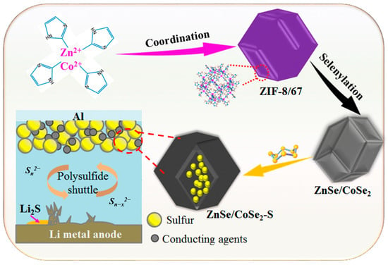
Figure 1.
Preparation flow chart of ZnSe/CoSe2–S electrode material.
3. Results and Discussion
3.1. Phase Characterization of Materials
Figure 2a shows the XRD characteristic peaks of the precursor of synthesized ZIF-8, ZIF-67, and ZIF-8/67 with different zinc–cobalt ratios (Zn1Co2–ZIF-8/67, Zn2Co1–ZIF-8/67, Zn1Co1–ZIF-8/67). The results show that all precursors have sharp peak shapes and excellent crystallinity. The crystal structures of ZIF-67 and ZIF-8 we prepared match well with those previously reported [12,13]. Moreover, the XRD results in Figure 2b show that all samples are pure phases according to PDF card ZnSe (PDF#88-2345) and CoSe2 (PDF#65-3327), which verifies that the synthesized Zn–Co bimetallic selenides are primarily composite materials of CoSe2 and ZnSe. Compared with ZnSe and CoSe2, the positive shift of the XRD peak and the decrease in crystallinity of the synthesized ZnSe/CoSe2 composite are due to an increase in deformation and disorder of crystal structure. For ZnSe, the XRD peaks at 27.2°, 45.2°, 53.2°, and 65.8° belong to the diffraction planes of (111), (220), (311), and (400), respectively. For CoSe2, the diffraction peaks at 26.32°, 30.49°, 34.19°, 37.57°, 51.70°, 56.59°, 58.93°, and 74.09° belong to the diffraction planes of (111), (200), (210), (211), (311), (023), (321), and (421), respectively. With the increase in Zn content, the intensity of ZnSe diffraction peaks (27.2° and 45.2°) in the ZnSe/CoSe2 XRD pattern becomes more and more prominent. As shown in Figure 2c, all composite materials mainly show the characteristic peak of sulfur, with sharp diffraction peaks at 23.05°, 25.83°, and 28.66°, which correspond to the standard card of S8 (PDF#83-2283).
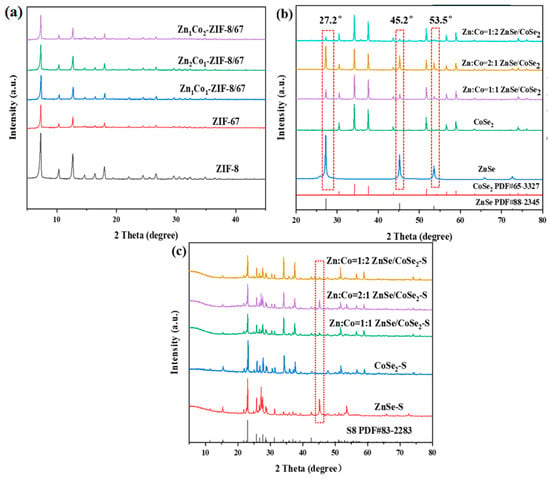
Figure 2.
(a) XRD patterns of ZIF-8, ZIF-67, and ZIF-8/67 precursors with different Zn–Co ratios; (b) XRD patterns of ZnSe, CoSe2, and ZnSe/CoSe2 composites with different Zn–Co ratios; (c) XRD patterns of ZnSe–S, CoSe2–S, and ZnSe/CoSe2–S cathode materials with different Zn–Co ratios.
3.2. Characterization of Morphology and Structure of Materials
A scanning electron microscope (SEM) test was carried out to observe the morphology and structure of samples. As shown in Supplementary Material Figure S1a,b, the morphologies of ZIF-8 and ZIF-67 precursors are both dodecahedron structures. The particles of ZIF-8 are relatively uniform and small, ranging from 150 to 200 nm. The ZIF-67 is larger and uneven; the particle size ranges from 300 to 400 nm. Figure S1c–e show the precursors of ZIF-8/67 with Zn:Co = 1:1, 2:1, and 1:2, respectively. The figures clearly show that ZIF-8/67 with different Zn/Co ratios well preserves the regular polyhedral structure of ZIF-8. The synthesized ZIF-8/67 material has a smooth surface, uniform particles, and suitable dispersion. The ratio of Zn to Co affects the size of the synthesized ZIF-8/67 precursor. Figure S1c shows that the size of ZIF-8/67 is 300 nm for Zn:Co = 1:1. As the Co content increases, the grain size increases due to the epitaxial growth of ZIF-67.
As shown in Figure 3a, the surface of ZnSe after selenization is rough, some particles are seriously agglomerated, and the morphology begins to collapse. The CoSe2 material in Figure 3b maintains better morphology, but the particle sizes are uneven, and the structures shrink inward, which causes the decomposition of the ZIF-67 precursor. The SEM images in Figure 3c–e show that the surface of the ZnSe/CoSe2 composites synthesized by selenization of the precursor materials with different zinc–cobalt ratios is no longer smooth. The broken ZnSe/CoSe2 particles can be seen in Figure 3c–e, indicating that the internal ZnSe/CoSe2 material presents a hollow structure. The ZnSe/CoSe2 (Zn:Co = 2:1 and Zn:Co = 1:2) composite materials shown in Figure 3d,e have uneven structure and size, and the surface is composed of many fine particles. With the increase in Co content, the calcined particles are still the largest in size, with a particle size of 300 nm. Compared with the ZnSe/CoSe2 material with Zn:Co = 1:1, the morphology is seriously damaged during calcination. Figure 3c shows that the ZnSe/CoSe2 composite material with Zn:Co = 1:1 basically maintains the previous polyhedral structure and has a more stable structure and uniform size.
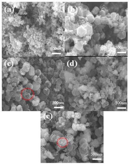
Figure 3.
SEM images of (a) ZnSe, (b) CoSe2, and (c–e) ZnSe/CoSe2 with different Zn-to-Co ratios are 1:1, 2:1, and 1:2, respectively.
The EDS analysis results of ZnSe/CoSe2 composite cathode materials with different Zn/Co ratios are shown in Figure S2. According to EDS data, Zn/Co = 1.00 is calculated, matching the ratio of Zn:Co = 1:1; Zn/Co = 1.57, slightly deviating from Zn:Co = 2:1; Zn/Co = 0.38, which is close to Zn:Co = 1:2 ratio. With the increase in cobalt content, the number of porous carbon skeletons in ZnSe/CoSe2 composite material (Zn:Co = 1:2) decreases, which indicates possessing suitable stability. However, the size and morphology are not conducive to the infiltration of electrolytes in the lithium–sulfur battery in Figure S2f. With the increase in Zn content, when Zn:Co = 2:1, the structure of ZnSe/CoSe2 composites collapse and agglomerate after high-temperature heat treatment, and the formed MOFs are unstable, which indicates that too-high Zn content is unfavorable to maintain the stability of the composites. The optimal Zn:Co molar ratio is 1:1.
The ZnSe/CoSe2 prepared by ZIF-8/67 has the best morphology when Zn:Co = 1:1. As shown in Figure 4, the morphology and structure of ZnSe/CoSe2 are further characterized by transmission electron microscope (TEM). Figure 4a exhibits that the synthesized ZnSe/CoSe2 has a hollow dodecahedron structure. The corresponding element distribution scanning is performed, and the distribution is observed in Figure 4b–f. Apparently, for the composite material, C, N, and Se elements are detected throughout the scan range and are uniformly distributed in the composite material. A small amount of Zn is located at the edge of the polyhedral framework, and most of the Co element is located at the two sides and the middle of the polyhedron, which also confirms that the nanoparticles ZnSe and CoSe2 are uniformly dispersed in the core-shell structure. Importantly, the composite material has a hollow structure, and a large number of voids between the hollow structures can not only encapsulate the single sulfur to improve the volume expansion but also reduce the aggregation and crushing of the electrode material, contributing to the stable cycling performance. The N-doped amorphous carbon in the whole material can provide a large number of reactive active sites and enhance conductivity.
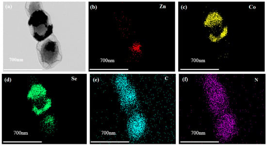
Figure 4.
(a) HAADF-STEM diagram of ZnSe/CoSe2 sample with Zn:Co = 1:1 and sections of Zn, Co, Se, C, and N elements distribution, and (b–f) Element distribution profiles of Zn, Co, Se, C and N, respectively.
Figure S3a is the TEM image of ZnSe/CoSe2, which shows a rhombic dodecahedron structure, corresponding to the morphology structure in the SEM image, further confirming that this material has a hollow structure and forms a carbon layer coating on the surface. Figure S3b,c corresponds to high-resolution images of the ZnSe/CoSe2 composites. The interplanar spacing in Figure S3b is 0.328 nm, representing the (111) plane of ZnSe. The other interplanar spacing of 0.331 nm corresponds to the (111) plane of CoSe2 and has a clear boundary with the lattice stripe of ZnSe. In Figure S3c, interplanar spacing of 0.264 nm corresponds to the (210) plane of CoSe2, indicating that the material is composed of ZnSe and CoSe2. Frequent lattice mismatch and distortion occur near the interface of Zn and Co, thus generating abundant reactive sites. Effective electrocatalysis accelerates the redox reaction kinetics of polysulfides and enhances the conversion rate of sulfur.
The porous structure and surface properties of ZnSe, CoSe2, and ZnSe/CoSe2 composites with different Zn/Co ratios are evaluated by the nitrogen adsorption–desorption technique. In Figure S4a, the adsorption isotherms of ZnSe, CoSe2, and ZnSe/CoSe2 composites with different Zn–Co ratios have obvious H3-type hysteresis loops at the relative pressure (P/P0) of 0.4–1.0, demonstrating the existence of mesopores and macropores. The pore size distributions of all of the synthetic materials are shown in Figure S4b, further indicating the presence of a hierarchical micropore-meso-macroporous void for all of the synthetic selenide materials. Micropores ensure the continuable limitation of electrolyte and soluble polysulfide, motivate the full wetting of the catalytic active sites, and thus promote the solid–liquid polysulfide conversion kinetics. In the continuous charging and discharging process, the mesopores can effectively mitigate the volume change. Moreover, the macroporous structure and larger pore volume provide ample storage space for a high sulfur load. Among ZnSe, CoSe2, and ZnSe/CoSe2 with different Zn–Co ratios, the pore volume of ZnSe is the largest (0.710 cm3 g−1). In addition, as shown in Table S1, with the increase in Zn content, the synthesized ZnSe/CoSe2 has a larger pore volume, but its specific surface area gradually decreases. The synthesized ZnSe/CoSe2 sample (Zn:Co = 1:1) has the largest BET surface area (317.991 m2 g−1), more than twice that of the CoSe2 sample (151.788 m2 g−1). The larger specific surface area brings more reaction active sites, which is beneficial to the electrochemical reaction kinetics. Therefore, when Zn:Co = 1:1, the synthesized ZnSe/CoSe2 composite has a large specific surface area, thereby providing more active areas for the adsorption–diffusion–conversion of polysulfides.
The ZnSe/CoSe2–S composite cathode material with Zn:Co = 1:1 was analyzed, and we determined the mass percentage of sulfur in the cathode composite material by thermogravimetric analysis. The temperature was raised from 30 °C to 600 °C at a heating rate of 10 °C min−1 under N2. Figure S5 shows the thermogravimetric curve results of the materials. The loss caused by sulfur evaporation is about 69.2%, which is consistent with the amount of sulfur added during the preparation process.
The elemental bond configuration and surface chemical state information of the ZnSe/CoSe2 composite with Zn:Co = 1:1 were conducted by XPS analysis. Figure 5a shows the wide-scan XPS spectrum of the ZnSe/CoSe2 sample. The Zn, Co, Se, C, and N elements can be obtained from the full spectrum. The peaks of Zn, Co, and Se were simulated by the Gaussian fitting method, showing typical Zn2p, Co2p, Se3d, C1s, and N1s, respectively. In Figure 5b, the XPS spectrum of Zn2p consists of two main peaks, centered at 1021.1 eV and 1044.19 eV, belonging to and of Zn2+, respectively [14]. Figure 5c shows the high-resolution spectrum of Co2p, the fitted peaks at 780.51 eV and 796.31 eV, respectively, corresponding to the spin-orbit doublets of and , and two satellite peaks at 788.22 eV and 805.2 eV correspond to the chemical state of Co2+ salt. The peaks at 784.22 eV and 801.54 eV represent Co3+ ions. This is mainly owing to the partial oxidation of the surface of CoSe2 after long-term exposure to air, which has been reported in other selenides as well [15,16,17]. In Figure 5d, it can be seen from the XPS spectrum of Se3d that the two fitted major peaks at 55.32 eV and 53.97 eV can be assigned to the metal selenides and , which can be attributed to the formation of Zn–Se and Co–Se bonds. The additional peak at 58.17eV is SeO2 because the Se surface shows a high degree of oxidation, and the formation of SeO2 is relevant to the interaction of oxygen and selenium on the surface, which is consistent with the results reported by previous studies [10,18,19,20,21]. Figure 5e shows the high-resolution spectrum of C1s. The peak at 285.5 eV is attributed to the C=N bond, indicating that the N element has been successfully doped into the amorphous carbon shell. The other three fitted peaks are at 284.2, 287.93, and 286.3 eV, corresponding to C=C, C=O, and C-O, respectively. Figure 5f shows the high-resolution spectrum of N1s, which has three peaks at 397.91 eV, 399.7 eV, and 401.5 eV, corresponding to pyrrole nitrogen, pyridine nitrogen, and graphitized nitrogen [15,17]. In general, the pyrrole and pyridine nitrogens can produce defective carbon shells that accelerate electron transfer [22].
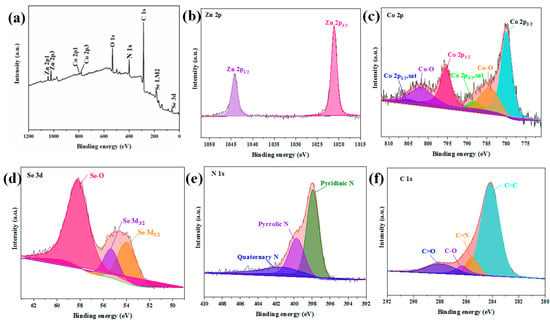
Figure 5.
(a) The survey XPS spectrum of ZnSe/CoSe2 with Zn:Co = 1:1 composite, (b) Zn2p XPS spectrum, (c) Co2p XPS spectrum, (d) Se3d XPS spectrum, (e) C1s XPS spectrum, and (f) N1s XPS spectrum.
3.3. Analysis of the Electrochemical Performance of the Materials
Figure 6a–e show the cyclic voltammetry (CV) curves of ZnSe–S, CoSe2–S, and ZnSe/CoSe2–S cathode materials with different Zn–Co ratios at 0.1 mV s−1. Figure 6a shows the CV curve of the ZnSe–S electrode. Two reduction peaks are located at 2.28 V and 2.01 V, which correspond to the long-chain lithium polysulfide (Li2Sn, 4 < n ≤ 8) formed by S8 breaking during the discharge process. With thorough discharging, long-chain lithium polysulfide is further reduced to form lithium sulfide (Li2Sn, n ≤ 2) insoluble in electrolyte [23]. The peak at 2.53 V is the oxidation peak, which is opposite to the discharge process and represents the reaction process of short-chain Li2S → intermediate long-chain lithium polysulfide → sulfur [24]. During the scanning process, the peak current and peak area of the ZnSe–S electrode decrease, and the peak deformation is widened with the increase in scanning cycles, which indicates that the capacity has a great loss. This is attributed to the “shuttle effect” of the ZnSe–S, which causes the irreversible oxidation and reduction reaction of sulfur, leading to the slow reaction speed and the low utilization of sulfur. Figure 6b,d are the CV curves of CoSe2–S and ZnSe/CoSe2–S composite materials with Zn:Co = 2:1, respectively. The figures show that two reduction peaks gradually shift negatively, whereas the oxidation peak shifts positively, which intensifies the polarization of electrode materials and slows down the S conversion during the charging and discharging process, leading to worse rate performance. Figure 6c,e show the CV curves of ZnSe/CoSe2–S composite materials when Zn:Co = 1:1 and Zn:Co = 1:2, respectively. The difference between the oxidation and reduction peak of ZnSe/CoSe2–S (Zn:Co = 1:1) is about 0.44 V, which is lower than 0.47 V of the ZnSe/CoSe2–S (Zn:Co = 1:2) composite positive electrode. Compared with the ZnSe/CoSe2–S (Zn:Co = 1:2) electrode, the peak current and peak area of the ZnSe/CoSe2–S material (Zn:Co = 1:1) are significantly increased, indicating a substantial increase in the capacity and stability of the battery. In the subsequent cycles, the CV curves show suitable superimposition and high reversibility. This is due to the synergism between different metal cations provided by ZnSe/CoSe2 materials, which enhance their electrochemical activity. The existence of ZnSe/CoSe2 materials well restrains the dissolution of polysulfides in organic electrolytes and catalyzes the rapid conversion of polysulfides, thus ensuring the effective use of sulfur and improving the electrochemical performance of the lithium–sulfur battery [25].
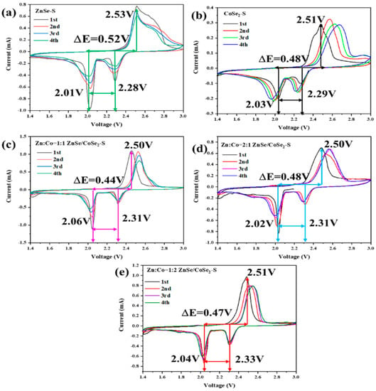
Figure 6.
CV curves of (a) ZnSe–S, (b) CoSe2–S, and (c–e) ZnSe/CoSe2–S cathode materials with different Zn–Co ratios at 0.1 mV s−1.
Figure 7a shows the cycle performance test of ZnSe–S, CoSe2–S, and ZnSe/CoSe2–S cathode materials with different Zn–Co ratios at 0.2 C. ZnSe/CoSe2–S (Zn:Co = 1:2) has the highest initial capacity(1015.84 mAh g−1) at 0.05 C, and the initial coulombic efficiency is 97.36%. However, when the discharge rate is 0.2 C, Zn:Co = 1:1, and the capacity of ZnSe/CoSe2–S electrode is much higher than the other materials. In addition, the ZnSe/CoSe2–S (Zn:Co = 1:1) electrode still has a reversible capacity of 377.44 mAh g−1 after 200 cycles, and its capacity retention is 47.8%. On the contrary, the capacity of ZnSe/CoSe2–S (Zn:Co = 1:2) electrode material decreases to 324.67 mAh g−1 after 200 cycles. The above results show that ZnSe/CoSe2–S (Zn:Co = 1:1) electrode has better electrochemical performance, which is attributed to a large number of voids in its hollow structure for sulfur storage, and a large number of voids can allow efficient adaptation for the volume change and improve its electrochemical performance. At the same time, numerous heterojunction interfaces between ZnSe and CoSe2 can cause lattice mismatches and distortions, promoting lithium-ion diffusion kinetics, generating a prominent pseudocapacitance effect, and increasing the specific capacity and the cycle performance [14,15,17,21]. Figure 7b compares the doubling performance of ZnSe–S, CoSe2–S, and ZnSe/CoSe2–S electrodes with different zinc–cobalt ratios. The specific discharge capacities of ZnSe/CoSe2–S electrode with Zn:Co = 1:1 are 1023.78, 780.22, 578.23, 456.24, 361.77, 280.05, and 111.62 mAh g−1, corresponding to 0.05 C, 0.1 C, 0.2 C, 0.5 C, 1 C, 2 C, and 5 C, respectively. They are rather higher than that of ZnSe–S electrode (974.03, 558.03, 375.79, 294.21, 231.25, and 114.49 mAh g−1) and CoSe2–S electrode (747.2, 520.68, 396.88, 310.9, 246.8, and 157.13 mAh g−1). The reversible capacity of 574.24 mAh g−1 still maintains when the current density returns to 0.1 C, which indicates that the ZnSe/CoSe2–S electrode has suitable cycle reversibility at Zn:Co = 1:1.
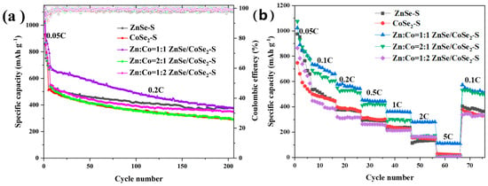
Figure 7.
(a) Cyclic curves of ZnSe–S, CoSe2–S, and ZnSe/CoSe2–S cathode materials with different Zn–Co ratios at low current densities of 0.2 C. (b) The rate properties of ZnSe–S, CoSe2–S, and ZnSe/CoSe2–S anode materials with different Zn–Co ratios at 0.05–5 C.
Because TMSs have a high theoretical specific capacity and can be applied to the positive and negative electrodes of various energy storage materials, in order to verify which active material provides the capacity generated by the electrode materials in the lithium–sulfur battery, ZnSe, CoSe2, and ZnSe/CoSe2 matrix materials are coated on aluminum foil to prepare positive electrode materials. Moreover, cycle tests are carried out under the voltage range of 1.6–2.8V. It can be seen from Figure S6a that when no sulfur is loaded, the capacities of electrodes composed of ZnSe, CoSe2, and ZnSe/CoSe2 materials are only 5, 12, and 6 mAh g−1, respectively, indicating that the capacities generated in ZnSe–S, CoSe2–S, and ZnSe/CoSe2–S electrodes are provided by ZnSe, CoSe2, and ZnSe/CoSe2–S materials in few proportions. The capacity generated by the composite electrode is provided by the redox reaction of the active material sulfur. Figure S6b shows the charge and discharge curves of ZnSe/CoSe2–S (Zn:Co = 1:1), ZnSe–S, and CoSe2–S electrodes. The ZnSe/CoSe2–S (Zn:Co = 1:1) composite electrode has a charge–discharge voltage difference value of 225 mV, smaller than that of ZnSe–S (240 mV) and CoSe2–S (289 mV) electrodes. This is owing to the synergistic effect between different metal cations of ZnSe/CoSe2 bimetallic selenides, and the effective electrocatalytic performance is beneficial to the enhancement of its electrochemical activity [26]. Figure S6c shows the cyclic performance of ZnSe/CoSe2–S (Zn:Co = 1:1) cathode material at 1 C. The figure shows that the electrode has excellent long-term cyclic stability. The initial capacity of the electrode is 363.76 mAh g−1. After 300 cycles, the final capacity is 300.85 mAh g−1, the capacity retention rate is 82.71%, and the capacity decay rate per cycle is 0.0576%. Figure S6d–f show the galvanostatic charge–discharge curves of ZnSe–S, CoSe2–S, and ZnSe/CoSe2–S electrodes (Zn:Co = 1:1) at different current densities from 0.05 C to 5 C. The ZnSe/CoSe2–S (Zn:Co = 1:1) cathode still maintains two discharge plateaus and high discharge capacity at 2 C, indicating that the conversion reaction of polysulfide is relatively rapid and the structure has suitable stability.
Figure 8 shows the electrochemical impedance spectroscopy (EIS) measurement results of ZnSe–S, CoSe2–S, and ZnSe/CoSe2–S electrode materials with different Zn–Co ratios before cycling. An equivalent circuit diagram is constructed according to the Nyquist curve and fitted with Zview software. The EIS diagram of each material includes a linear part in the low-frequency region and a quasi-semicircle in the high-frequency region. At the high-frequency region, the semi-circular diameter determines the charge transfer resistance (Rct) of the electrode, which represents the rate of charge transfer between the electrolyte and electrode material interface [24,25,26,27]. It can be seen from Figure 8 that, compared with ZnSe–S and CoSe2–S electrode active materials, the semicircle of ZnSe/CoSe2–S electrodes with different Zn–Co ratios is obviously smaller. The Rct of ZnSe–S, CoSe2–S, and ZnSe/CoSe2–S electrodes with different Zn–Co ratios obtained by fitting are 89.89, 84.02, 51.53, 73.33, and 56.66 Ω, respectively. It can be seen from the results that the Rct of the ZnSe/CoSe2–S (Zn:Co = 1:1) electrode is the minimum, indicating that the electrode material prepared with Zn:Co = 1:1 has high electron transport kinetics, and the synergistic effect of Zn and Co metal is beneficial to inducing charge transfer resistance, thus showing suitable electrochemical performance. In the low-frequency region, the slope of the curve represents the ion diffusion resistance (WO) [28]. It can be found that the straight line of the ZnSe/CoSe2–S electrode (Zn:Co = 1:1) is more inclined to the y-axis, so this electrode has lower WO than the other four electrode materials in the electrochemical process, indicating that the ion absorption–desorption and charge transfer speed at the interface is faster.
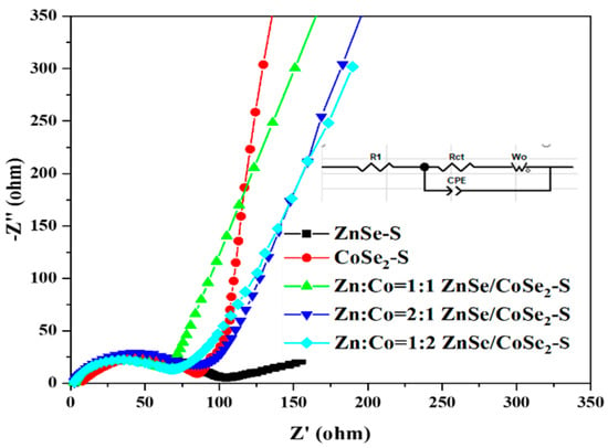
Figure 8.
EIS spectra of ZnSe–S, CoSe2–S, and ZnSe/CoSe2–S with different Zn–Co ratios electrode materials before cycling.
In order to verify the strong trapping ability of the synthesized TMSs to polysulfides, a visual adsorption experiment was carried out. A total of 10 mg of ZnSe, CoSe2, and ZnSe/CoSe2 composite materials with different zinc and cobalt ratios were respectively added into the prepared diluted Li2S6 solution. The fading degree of the solution revealed the adsorption ability of the materials to lithium polysulfide. As shown in Figure S7, after 12 h, the fading of CoSe2 and ZnSe/CoSe2 composite materials prepared with Zn:Co = 1:1 are more obvious, indicating that both of their adsorption ability is best. In addition, UV-vis absorption spectrum analysis was carried out on the above solution after adsorption, and the results are shown in Figure S8b. The peak at 416 nm is associated with S62−, indicating the presence of Li2S6 in the solution [29]. The UV results show that the peak intensity of the five selenide materials is weakened, which indicates that all of the five selenide materials have an adsorption effect on Li2S6, which is due to the fact that ZnSe has a strong adsorption effect on polysulfides and can regulate their conversion reaction, while the conductive CoSe2 surface provides a fast lithium-ion diffusion path to speed up the polysulfide conversion [30]. By combining the respective advantages of bimetallic selenides, ZnSe and CoSe2 jointly promote the conversion of lithium polysulfide, accelerate the oxidation-reduction reaction of the lithium polysulfide, and increase the availability of sulfur.
In order to further confirm that ZnSe, CoSe2, and ZnSe/CoSe2 composite materials with different Zn/Co ratios have catalytic effects on lithium polysulfide, the composite matrix materials were assembled into symmetrical batteries to test CV curves with or without Li2S6 added into the electrolyte. In Figure S8a, the symmetric battery with Li2S6 solution added in the electrolyte shows an obvious redox peak with a large and obvious peak current value, while the electrode without Li2S6 added has almost no peak shape and zero peak current and has no response, which indicates that the TMSs could catalyze and accelerate the conversion of lithium polysulfide. Compared with ZnSe and ZnSe/CoSe2 composite electrodes with other Zn/Co ratios, CoSe2 and the ZnSe/CoSe2 composite electrodes with Zn:Co = 1:1 exhibit higher current densities, which indicates that the conversion reaction of lithium polysulfide is significantly promoted, which is also in agreement with the results of visible adsorption experiments of polysulfide.
4. Conclusions
ZnSe/CoSe2 composites can be prepared by controlling the ratio of Zn–Co in the MOFs of ZIF-67 and ZIF-8. Due to the synergistic effect, the specific capacities of the double-metal Zn–Co selenides with dodecahedron hollow structures are higher than those of the electrodes formed by ZnSe or CoSe2 single-metal selenides. With zinc content increasing, the electrochemical activity of the bimetallic selenides increases first and then decreases. The ZnSe/CoSe2–S electrode, at the Zn-to-Co optimal ratio of 1:1, has a 790.06 mAh g−1 initial specific capacity at 0.2 C and excellent cycle stability. The excellent performance of the prepared Zn–Co bimetallic selenide composites is due to the advantages of the selenium composition, the dodecahedron, and the hollow structure. The less-electronegative selenium anion can provide better metal conductivity. The bimetal can furnish a synergistic effect between different metal cations, which is beneficial to enhancing its electrochemical activity. From the structure analysis, the larger the specific surface area of the dodecahedron, the more electroactive sites there are. The hollow structure can store the active sulfur, buffer the volume change of the active material in the charging and discharging process, make the electrolyte ions diffuse rapidly, and enable the lithium–sulfur battery to have superior electrochemical properties.
Supplementary Materials
The following supporting information can be downloaded at: https://www.mdpi.com/article/10.3390/batteries9060307/s1. Figure S1: SEM images of (a) ZIF-8, (b) ZIF-67, (c–e) ZIF-8/67 with different Zn to Co ratios are 1:1, 2:1, and 1:2, respectively; Figure S2: SEM and EDS of (a,b) Zn:Co = 1:1, ZnSe/CoSe2 sample, (c,d) Zn:Co = 2:1, ZnSe/CoSe2 sample, (e,f) Zn:Co = 1:2, ZnSe/CoSe2 sample; Figure S3: TEM images of (a–c) ZnSe/CoSe2 with Zn:Co = 1:1 at low and high magnification; Figure S4: ZnSe, CoSe2, and ZnSe/CoSe2 composites with different Zn/Co ratios (a) N2 absorption and desorption curves; (b) pore size distribution; Figure S5: Thermogravimetric curves of Zn:Co = 1:1, ZnSe/CoSe2-S composites; Figure S6: (a) Diagram of cyclic properties of ZnSe, CoSe2 and ZnSe/CoSe2 materials at 0.2 C; (b) Charge-discharge curve platform of ZnSe-S, CoSe2-S, and Zn:Co = 1:1 for ZnSe/CoSe2-S cathode material composites at 0.05 C; (c) Cyclic properties of Zn:Co = 1:1 for ZnSe/CoSe2-S cathode material at 1 C; Charge and discharge curves of (d) ZnSe-S, (e) CoSe2-S and (f) Zn:Co = 1:1 for ZnSe/CoSe2-S cathode material composites at different current densities; Figure S7: Diagram of the adsorption of Li2S6 solution by composite substrate with time change: a. 0 h; b. 2 h; c. 4 h; d. 8 h; e. 12 h; Figure S8: CV curves of ZnSe, CoSe2, and ZnSe/CoSe2 matrix composites with different Zn-Co ratios between −1.0~1.0 V at 5 mV s−1 scanning rate and (b) UV-vis spectra of adsorbed Li2S6 solution by ZnSe, CoSe2 and ZnSe/CoSe2 matrix composites with different Zn-Co ratios; Table S1: BET results of ZnSe, CoSe2, and ZnSe/CoSe2 composites with different Zn/Co ratios.
Author Contributions
Conceptualization, D.L. and X.Q.; methodology, Z.L.; software, H.P.; validation and data curation, D.L., H.P., Z.L. and X.Q.; writing—original draft preparation, D.L. and X.Q.; writing—review and editing, H.P. and Z.L.; visualization, X.Z.; supervision and funding acquisition, W.Z. and W.Y.; project administration, F.R. All authors have read and agreed to the published version of the manuscript.
Funding
The authors gratefully acknowledge the financial support from the Natural Science Foundations of Guangdong (2022A1515011715), the National Natural Science Foundation of China (21975056 and 52002079), Guangdong University Students’ Science and Technology Innovation Cultivation Special Fund (pdjh2023b0416), and Guangzhou University Student Innovation Training Project (202211078126 and xj202211078120).
Data Availability Statement
Not applicable.
Acknowledgments
The authors gratefully acknowledge the financial support from the Natural Science Foundations of Guangdong (2022A1515011715), the National Natural Science Foundation of China (21975056 and 52002079), Guangdong University Students’ Science and Technology Innovation Cultivation Special Fund (pdjh2023b0416), and Guangzhou University Student Innovation Training Project (202211078126 and xj202211078120).
Conflicts of Interest
The authors declare no conflict of interest.
References
- Elizalde-Segovia, R.; Irshad, A.; Zayat, B.; Narayanan, S.R. Solid-State lithium-Sulfur battery based on composite electrode and bi-layer solid electrolyte operable at room temperature. J. Electrochem. Soc. 2020, 167, 140529. [Google Scholar] [CrossRef]
- Ye, Z.Q.; Jiang, Y.; Li, L.; Wu, F.; Chen, R.J. Synergetic anion vacancies and dense heterointerfaces into bimetal chalcogenide nanosheet arrays for boosting electrocatalysis sulfur conversion. Adv. Mater. 2022, 34, 2109552. [Google Scholar] [CrossRef] [PubMed]
- Xie, Y.H.; Cao, J.Q.; Wang, X.H.; Li, W.Y.; Deng, L.Y.; Ma, S.; Zhang, H.; Guan, C.; Huang, W. MOF-derived bifunctional Co0.85Se nanoparticles embedded in N-doped carbon nanosheet arrays as efficient sulfur hosts for lithium-sulfur batteries. Nano Lett. 2021, 21, 8579–8586. [Google Scholar] [CrossRef] [PubMed]
- Cleaver, T.; Kovacik, P.; Marinescu, M.; Zhang, T.; Offer, G. Commercializing lithium sulfur batteries: Are we doing the right research? J. Electrochem. Soc. 2018, 165, A6029–A6033. [Google Scholar] [CrossRef]
- Wang, M.Q.; Liu, X.L.; Qin, B.Y.; Li, Z.Y.; Zhang, Y.F.; Yang, W.; Fan, H.S. In-situ etching and ion exchange induced 2D-2D MXene@Co9S8/CoMo2S4 heterostructure for superior Na+ storage. Chem. Eng. J. 2022, 451, 138508. [Google Scholar] [CrossRef]
- Ng, S.F.; Lau, M.Y.; Ong, W.J. Lithium-sulfur battery cathode design: Tailoring metal-based nanostructures for robust polysulfide adsorption and catalytic conversion. Adv. Mater. 2021, 33, 2008654. [Google Scholar] [CrossRef]
- Li, J.Y.; Niu, X.L.; Zeng, P.; Chen, M.F.; Pei, Y.; Li, L.Y.; Luo, Z.G.; Wang, X.Y. Double bond effects induced by iron selenide as immobilized homogenous catalyst for efficient polysulfides capture. Chem. Eng. J. 2021, 421, 129770. [Google Scholar] [CrossRef]
- Sun, W.W.; Li, Y.J.; Liu, S.K.; Liu, C.; Tan, X.J.; Xie, K. Mechanism investigation of iron selenide as polysulfide mediator for long-life lithium-sulfur batteries. Chem. Eng. J. 2021, 416, 129166. [Google Scholar] [CrossRef]
- Xiao, W.S.; He, Q.; Zhao, Y. Virtual screening of two-dimensional selenides and transition metal doped SnSe for lithium-sulfur batteries: A first-principles study. Appl. Surf. Sci. 2021, 570, 151213. [Google Scholar] [CrossRef]
- Chen, H.C.; Chen, S.; Fan, M.D.; Li, C.; Chen, D.; Tian, G.L.; Shu, K.Y. Bimetallic nickel cobalt selenides: A new kind of electroactive material for high-power energy storage. J. Mater. Chem. A 2015, 3, 23653–23659. [Google Scholar] [CrossRef]
- Chen, T.M.; Shang, Z.C.; Yuan, B.; Wu, N.X.; Abuzar, M.; Yang, J.Y.; Gu, X.X.; Miao, C.Y.; Ling, M.; Li, S. Rational design of Co-NiSe2@N-doped carbon hollow structure for enhanced Li–S battery performance. Energy Technol. 2020, 8. [Google Scholar] [CrossRef]
- Zhang, Z.H.; Zhang, J.L.; Liu, J.M.; Xiong, Z.H.; Chen, X. Selective and competitive adsorption of azo dyes on the metal-organic framework ZIF-67. Water Air Soil Pollut. 2017, 227, 471. [Google Scholar] [CrossRef]
- Park, K.S.; Ni, Z.; Cote, A.P.; Choi, J.Y.; Huang, R.D.; Uribe-Romo, F.J.; Chae, H.K.; Yaghi, O.M. Exceptional chemical and thermal stability of zeolitic imidazolate frameworks. Proc. Natl. Acad. Sci. USA 2006, 103, 10186–10191. [Google Scholar] [CrossRef]
- Zhang, X.Y.; Lv, X.L.; Wei, C.G.; Wang, J.G. Highly sulfiphilic zinc selenide/carbon regulators for high-capacity and long-lifespan Li-S batteries. Appl. Surf. Sci. 2021, 568, 150952. [Google Scholar] [CrossRef]
- Liu, J.B.; Lin, C.J.; Xie, Q.S.; Peng, D.L.; Xie, R.J. Core–shell zeolite imidazole framework-derived ZnSe@CoSe2/C heterostructure enabling robust polysulfide adsorption and rapid Li+ diffusion in high-rate and high-loading lithium-sulfur batteries. Chem. Eng. J. 2022, 430, 133099. [Google Scholar] [CrossRef]
- Ye, Z.Q.; Jiang, Y.; Li, L.; Wu, F.; Chen, R.J. Self-assembly of 0D–2D heterostructure electrocatalyst from MOF and MXene for boosted lithium polysulfide conversion reaction. Adv. Mater. 2021, 33, 2101204. [Google Scholar] [CrossRef]
- Ye, Z.Q.; Jiang, Y.; Li, L.; Wu, F.; Chen, R.J. Engineering catalytic CoSe-ZnSe heterojunctions anchored on graphene aerogels for bidirectional sulfur conversion reactions. Adv. Sci. 2022, 9, 2103456. [Google Scholar] [CrossRef]
- Cheng, L.; Zhai, Q.C.; Chen, S.S.; Li, Y.M.; Chen, J.X.; Lou, Y.B. Component-tunable hierarchical flower-shaped bimetallic zinc-cobalt selenides for high-performance hybrid supercapacitor. J. Energy Storage 2021, 36, 36–102374. [Google Scholar] [CrossRef]
- Fang, G.Z.; Wang, Q.C.; Zhou, J.; Lei, Y.P.; Chen, Z.X.; Wang, Z.Q.; Pan, A.Q.; Liang, S.Q. Metal organic framework-templated synthesis of bimetallic selenides with rich phase boundaries for sodium-ion storage and oxygen evolution reaction. ACS Nano 2019, 13, 5635–5645. [Google Scholar] [CrossRef]
- Huang, F.; Wang, L.; Qin, D.C.; Xu, Z.B.; Jin, M.Q.; Chen, Y.; Zeng, X.X.; Dai, Z.H. Constructing heterostructured bimetallic selenides on an N-doped carbon nanoframework as anodes for ultrastable Na-ion batteries. ACS Appl. Mater. Interfaces 2022, 14, 1222–1232. [Google Scholar] [CrossRef]
- Sakthivel, M.; Ramaraj, S.; Chen, S.M.; Ho, K.C. Bimetallic vanadium cobalt diselenide nanosheets with additional active sites for excellent asymmetric pseudocapacitive performance: Comparing the electrochemical performances with M-CoSe2 (M = Zn, Mn, and Cu). J. Mater. Chem. A 2019, 7, 12565–12581. [Google Scholar] [CrossRef]
- Geng, P.B.; Cao, S.; Guo, X.T.; Ding, J.W.; Zhang, S.T.; Zheng, M.B.; Pang, H. Polypyrrole coated hollow metal-organic framework composites for lithium-sulfur batteries. J. Mater. Chem. A 2019, 7, 19465–19470. [Google Scholar] [CrossRef]
- Deng, R.Y.; Wang, M.; Yu, H.Y.; Luo, S.R.; Li, J.H.; Chu, F.L.; Liu, B.; Wu, F.X. Recent advances and applications toward emerging lithium-sulfur batteries: Working principles and opportunities. Energy Environ. Mater. 2022, 5, 777–799. [Google Scholar] [CrossRef]
- Tan, J.; Matz, J.; Dong, P.; Ye, M.X.; Shen, J.F. Appreciating the role of polysulfides in lithium-sulfur batteries and regulation strategies by electrolytes engineering. Energy Storage Mater. 2021, 42, 645–678. [Google Scholar] [CrossRef]
- Canas, N.A.; Hirose, K.; Pascucci, B.; Wagner, N.; Friedrich, K.A.; Hiesgen, R. Investigations of lithium-sulfur batteries using electrochemical impedance spectroscopy. Electrochim. Acta 2013, 97, 42–51. [Google Scholar] [CrossRef]
- Deng, Z.F.; Zhang, Z.A.; Lai, Y.Q.; Liu, J.; Li, J.; Liu, Y.X. Electrochemical impedance spectroscopy study of a lithium/sulfur battery: Modeling and analysis of capacity fading. J. Electrochem. Soc. 2013, 160, A553–A558. [Google Scholar] [CrossRef]
- Walus, S.; Baechasz, C.; Bouchet, R.; Allion, F. Electrochemical impedance spectroscopy study of lithium-sulfur batteries: Useful technique to reveal the Li/S electrochemical mechanism. Electrochim. Acta 2020, 359, 136944. [Google Scholar] [CrossRef]
- Wang, N.N.; Zhang, X.; Ju, Z.Y.; Yu, X.W.; Wang, X.Y.; Du, Y.; Bai, Z.C.; Dou, S.X.; Yu, G.H. Thickness-independent scalable high-performance Li-S batteries with high areal sulfur loading via electron-enriched carbon framework. Nat. Commun. 2021, 12, 4519. [Google Scholar] [CrossRef]
- Liu, J.; Xue, M.Y.; Zhou, Y.H.; Liu, S.; Yan, T.Y. Effective chemisorption of polysulfides through organic molecules for high-performance lithium-sulfur batteries. Chem. Eng. J. 2023, 459, 459–141556. [Google Scholar] [CrossRef]
- Xu, J.; Xu, L.L.; Zhang, Z.L.; Sun, B.; Jin, Y.; Jin, Q.Z.; Liu, H.; Wang, G.X. Heterostructure ZnSe-CoSe2 embedded with yolk-shell conductive dodecahedral as Two-in-one hosts for cathode and anode protection of Lithium-Sulfur full batteries. Energy Storage Mater. 2022, 47, 223–234. [Google Scholar] [CrossRef]
Disclaimer/Publisher’s Note: The statements, opinions and data contained in all publications are solely those of the individual author(s) and contributor(s) and not of MDPI and/or the editor(s). MDPI and/or the editor(s) disclaim responsibility for any injury to people or property resulting from any ideas, methods, instructions or products referred to in the content. |
© 2023 by the authors. Licensee MDPI, Basel, Switzerland. This article is an open access article distributed under the terms and conditions of the Creative Commons Attribution (CC BY) license (https://creativecommons.org/licenses/by/4.0/).