Abstract
The changes in global energy trends and the high demand for secondary power sources, have led to a renewed interest in aqueous lithium-ion batteries. The selection of a suitable anode for aqueous media is a difficult task because many anode materials have poor cycling performance due to side reactions with water or dissolved oxygen. An effective method for improving the characteristics of anodes in aqueous electrolyte solutions is adding carbon nanotubes (CNTs) to the electrode materials. For a better comprehension of the mechanism of energy accumulation and the reasons for the loss of capacity during the cycling of chemical current sources, it is necessary to understand the behaviour of the constituent components of the anodes. Although CNTs are well studied theoretically and experimentally, there is no information about their behaviour in aqueous solutions during the intercalation/deintercalation of lithium ions. This work reveals the mechanism of operation of untreated and annealed single-walled carbon nanotubes (SWCNT) anodes during the intercalation/deintercalation of Li+ from an aqueous 5 M LiNO3 electrolyte. The presence of -COOH groups on the surface of untreated SWCNTs is the reason for the low discharge capacity of the SWCNT anode in 5 M LiNO3 (3 mAh g−1 after 100 cycles). Their performance was improved by annealing in a hydrogen atmosphere, which selectively removed the -COOH groups and increased the discharge capacity of SWCNT by a factor of 10 (33 mAh g−1 after 100 cycles).
1. Introduction
A typical Li-ion cell consists of three electrochemically active parts—an anode, a cathode, and a conducting electrolyte [1]. A cathode, generally made from a lithium metal oxide, acts during discharge as a positive terminal, and an anode, commercially composed of graphitic carbon, is the negative cell terminal [2,3,4]. The electrolyte is usually a lithium salt such as lithium hexafluorophosphate (LiPF6) dissolved in an organic solvent, e.g., a mixture of ethylene carbonate and diethyl carbonate [5,6,7,8,9]. Despite the wide use of lithium-ion batteries (LIBs) with LiPF6 electrolytes, they have some important disadvantages; the main disadvantages are the flammability of organic compounds used as electrolyte solvents (primarily based on carbonate esters) and their high cost [8,10]. Thus, during the operation of the batteries, it is necessary to control their temperature, which may increase with prolonged exposure to sunlight on the battery or with intensive use of mobile devices. At high temperatures (around 55 °C), LiPF6 decomposes to form pentafluorophosphorane (PF5), which interacts with a solvent and forms highly toxic substances [11,12,13]. For example, the PF6- anion is highly reactive in dipolar aprotic solvents based on carbonates with weak nucleophiles, so the presence of trace amounts of water or alcohols can lead to the formation of hydrogen fluoride [14,15,16,17]. The unsafety of organic electrolytes led to attempts in the early 1990s to use aqueous electrolytes in LIBs. The main advantages of aqueous electrolytes are that they are non-flammable, cheap, have very high ionic conductivity, and can operate at very high power densities [18,19]. However, in the mid-1990s, aqueous electrolytes were not widely used in LIBs for two reasons: the narrow 1.23 V potential window of aqueous electrolytes and the lack of electrochemical performance of the existing materials. The research rate on aqueous LIBs remained low over the next decade due to their uncertain economic viability and the commercial success of LIBs with organic electrolytes. At the same time, the improvement of LIBs did not stop: the advances in materials science and nanochemistry led to the emergence of new materials that can also be used as positive and negative electrodes in aqua-based LIBs.
Since the mid-2010s, electronics are rapidly becoming smaller and are actively used in everyday life. The changes in global energy trends, including making materials more sustainable and reducing energy costs, as well as the high demand for secondary power sources, have led to a renewed interest in aqueous LIBs. Neutral solutions of LiNO3 and Li2SO4 have become the most used electrolytes for experiments [10,20]. Studies have shown that cathodes, such as LiFePO4 and LiMn2O4, used for non-aqueous electrolytes are also stable in aqua-based solutions [21,22,23].
However, the suitable anode choice for aqueous media was a difficult challenge due to the dissolution of the material in the electrolyte and their oxidation in the discharged state [23,24]. At first, for aqueous LIBs as the anode material monoclinic, metastable VO2(B) was used, but in this case, Li+ intercalation was optimal only at an alkaline pH [25,26]. G.X. Wang and co-authors [27] showed the possibility of using lithium-rich spinel (Li2Mn4O9, Li4Mn5O12) and lithium titanate (Li4Ti5O12) with LiNO3 + LiOH water-based electrolyte instead of vanadate electrodes. The use of lithium titanate as an anode is complicated because titanate has a high water-splitting tendency, which works against the intended application as the anode in aqueous solutions. H. Wang and co-authors [28] showed that pyrophosphate TiP2O7 and NASICON-type LiTi2(PO4)3 can be used as anode materials for aqua-based batteries, but at the same time, due to side reactions of water and oxygen, they demonstrated a poor cycling performance. Further research has shown that carbon coating is an effective method for improving the performance of anodes in aqueous electrolyte solutions [24]—electrode materials modified by carbon nanotubes (CNTs) demonstrated significantly improved electrochemical properties [29,30,31,32]. These results showed that the addition of CNTs to the active material can provide higher conductivity, a better rate performance, and also improve capacity retention during cycling by avoiding contact loss between active particles. J. Barraza-Fierro with co-authors [33] described the electrochemical behaviour of multi-walled carbon nanotubes (MWCNTs) in an acidic aqueous electrolyte (1 M LiNO3/HNO3 with pH = 2) in the potential range of 0.4–1.4 V vs. Ag/AgCl. However, in this potential range (0.4–1.4 V vs. Ag/AgCl), lithium intercalation in MWCNTs did not occur, so it does not allow for the evaluation of the applicability of MWCNTs as an anode. Additionally, to the best of our awareness, there is no cyclic testing of carbon nanotube anodes in water-based electrolytes, which leads to a lack of knowledge about the behaviour of both multi-walled (MWCNT) and single-walled carbon nanotubes (SWCNT) during the intercalation/deintercalation of lithium in aqueous solutions. MWCNTs represent several tubes nested inside each other, while the SWCNTs are one layer thick; therefore, to understand the mechanism of lithium intercalation/deintercalation and to investigate the related processes, it is necessary to start the investigation with SWCNTs, as they have a more basic structure.
SWCNTs have a large surface area and easily interact with atmospheric gases (for example, CO and CO2), which can lead to the formation of carboxyl groups on the surface of nanotubes [34]. These carboxyl groups can affect the surface chemistry and electronic properties of SWCNTs, and their performance in energy storage devices [35,36]. Annealing can be used to remove -COOH groups from SWCNTs and restore their original properties. While there is research on the effect of annealing on the performance of SWCNTs for applications such as sensors [37], there is no information specifically focused on the performance of SWCNTs’ anodes in aqueous environments after annealing. Meanwhile, in non-aqueous electrolytes, the annealing leads to a 7-fold increase in the Li-ion storage capacity for a SWCNT cathode after its annealing [38].
In this work, the electrochemical behaviours of untreated and annealed SWCNTs anodes during Li+ intercalation/deintercalation processes from the 5 M LiNO3 electrolyte are investigated.
2. Experimental Part
The SWCNT film sample was fabricated using CNT (0.6 mg) deposition on a glass slide (1.0 × 2.5 cm). One edge (1.0 × 1.0 cm) was covered by a 50 nm thick gold electrode. For the preparation of the sample, 5 ± 0.01 mg of SWCNTs (Nano RAY-T Ltd., Stopinu Parish, Latvia) were weighed, mixed with 50 mL of isopropanol (98%), and placed in an ultrasonic bath for 15 min to achieve a homogeneous suspension (Figure 1). The obtained suspension was sprayed on a hot (150 °C) microscope glass slide with a spray gun until the predetermined weight (0.6 mg) was reached. To anneal the sample, a single thermal reduction step for 1 h at a temperature of 400 °C under 200 sccm H2/2000 sccm Ar flow was performed. The 400 °C temperature was chosen, because it represents the conditions, at which CNT based heterostructures using physical vapor deposition are fabricated [39]. The annealing at this temperature can enable more efficient synthesis, as multiple steps can be performed without the heating/cooling of the substrate.
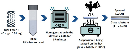
Figure 1.
Schematic illustration of the preparation of SWCNTs samples.
Further in the text, untreated and annealed samples will be designated u-SWCNT and a-SWCNT, respectively. Electric contacts were fabricated using the thermal evaporation method in the Sidrabe SAF EM device with gold pellets as evaporation materials (Kurt J. Lesker Company, Jefferson Hills, PA, USA, purity 99.99%, EVMAU40SHOT).
The morphology of the SWCNTs samples was investigated with a scanning electron microscope (SEM) “Hitachi FE-SEM S-4800”. The chemical composition of the samples was investigated by energy-dispersive X-ray spectroscopy (EDX) “Bruker XFLASH 5010” and Fourier transform infrared spectroscopy (FTIR). The FTIR spectrum was obtained in the frequency range 4000 to 400 cm−1 by PerkinElmer FT-IR/FIR Spectrometer Frontier. For the FTIR analysis, the SWCNTs sample was pressed with KBr pellets with the ratio of 1:600 of SWCNTs:KBr, respectively. The spectrum was analyzed by the catalogue of Spectrometric Identification of Organic Compounds [40].
Cyclic voltammetry (CV) and electrochemical impedance spectroscopy (EIS) were performed to characterise the electrochemical properties of SWCNTs samples. The electrochemical investigations were carried out using a PalmSens4 potentiostat/galvanostat. As an electrolyte, 5 M LiNO3 (Thermo Fischer, Waltham, MA, USA, purity 99%) was used. During the electrochemical measurements, a 3-electrode laboratory-made electrochemical cell system with SWCNT film as a working electrode, Ag/AgCl in aqueous 3 M KCl as a reference electrode, and Pt wire as a counter electrode were used [41,42]. The active mass loading of the electrode was 0.5 mg/cm2. Cyclic voltammetry curves were measured at the potential range from −0.2 V to +0.6 V vs. Ag/AgCl at a scan rate of 0.5 mV s−1. Electrochemical impedance spectra were measured in the frequency range of 0.1–10,000 Hz at the open circuit potential. The equivalent electrical circuits for the SWCNTs in 5 M LiNO3 were acquired from the impedance hodographs. The spectra complied with the Kramers–Kronig relations [43]. The selection of equivalent circuits and calculations of their parameters were performed by the Levenberg-Marquardt method. Galvanostatic charge/discharge measurements were performed in the potential range from −0.2 V to 0.5 V vs. Ag/AgCl at a C-rate of 0.5 C.
3. Results and Discussion
3.1. Effect of Annealing on the Structure of SWCNTs Samples
There is almost no change in SWCNTs morphology before and after annealing (Figure 2a,d). C, O, and Fe elements were identified in SWCNTs samples (Table 1). As-prepared SWCNT before annealing (u-SWCNT) predominantly consisted of carbon (~86%) and oxygen (~13%) with Fe impurities (0.7%) from the precursor used in synthesis. On the other hand, for the annealed sample, the amount of oxygen is only ~2% (sample a-SWCNT, Table 1) showing a successful reduction of the sample; furthermore, the iron impurity level dropped almost to zero (the carbon and oxygen values also include the background from the SEM/EDX chamber and from the glass substrate on which the CNTs are deposited). Full EDX spectra (Supplementary Figures S1–S4) and mapping data (Supplementary Figures S5–S8), which include background signals from the glass substrate, for u-SWCNT and a-SWCNT samples are presented in supplementary information.
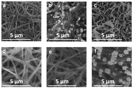
Figure 2.
SEM images of the u-SWCNT (a–c) and a-SWCNT (d–f) in 5 M LiNO3 before cycling (a,d), after the 5th cycle (b,e) and after the 100th cycle (c,f).

Table 1.
The relative content of elements (atom, %) in SWCNTs samples.
The FTIR spectra of u-SWCNT (Figure 3) shows a wide band at 3437 cm−1 corresponding to O–H stretching vibrations. The C=O (at 1717 cm−1) and C–O (at 1104 cm−1) peaks represent the presence of the carboxyl groups. These carboxyl groups can emerge from adsorbed CO and CO2 in u-SWCNTs due to surface oxidation that can occur when CNTs after synthesis are released into the laboratory environment [34]. The peak at 1435 cm−1 is associated with aromatic C=C. The lines at 677 cm−1 and 1644 cm−1 are characteristic of alkene =C–H groups and vibrations of the C=C covalent bonds, respectively [44]. The peak at 2030 cm−1 corresponds to the C=O group, characteristic of mononuclear metal carbonyls, and the peak at 482 cm−1 corresponds to vibrations of the Fe-CO bond [40,44]. The peak at 2350 cm−1 corresponds to atmospheric carbon dioxide and is used for calibration. Obtained results were in good agreement with the literature data of FTIR spectra for carbon nanomaterials [45,46].
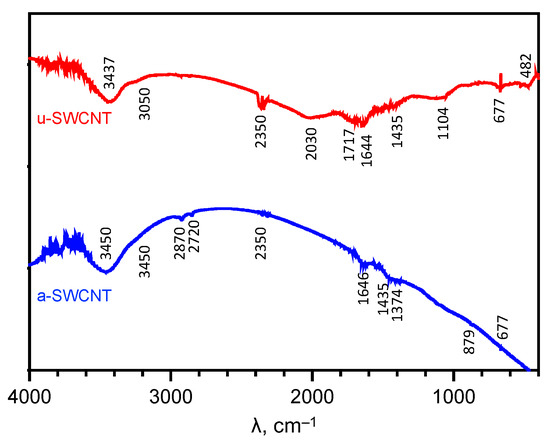
Figure 3.
FTIR spectra of the investigated SWCNTs samples.
For the a-SWCNT sample, the carboxyl groups are reduced to –CH3 groups, as evidenced by the appearance of a band at 1375 cm−1. There are no peaks characterizing the C–O and C=O bonds in the spectrum. However, there is a broad band at 3450 cm−1, this O–H stretching mode is more likely due to adsorbed water molecules. The absorption bands at 2870 cm−1 characterize asymmetric vibrations of -CH2- groups and at 2720 cm−1 characterize fluctuations in the C-H bond. The peak at 879 cm−1 indicates the presence of iron carbonate Fe2CO3 or, more likely, Fe2CO3(OH)2 [47]. Additionally, as reported by Zhang et al. [48], the removal of the oxygen-containing functional groups create nanowindows in the SWCNT’s graphene sheet and lead to the increased overall porosity of the material.
Schematically, possible changes in the SWCNTs structure during annealing are shown in Figure 4.
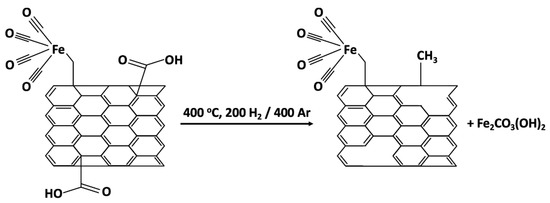
Figure 4.
The scheme of the possible changes in SWCNTs structure during annealing.
3.2. Effect of Annealing on the Electrochemical Properties of SWCNTs Anodes in 5M LiNO3
The impedance spectra are arranged in the form of stable graphs, which is also typical for other promising anodes for LIBs [49,50,51,52]. The acquired experimental dependences of the Nyquist impedance hodographs for a-SWCNT have the form of a part of a semicircle with the center lying below the abscissa axis, and therefore the classical Randles scheme cannot be used to describe this impedance. To describe this type of curve, the constant phase (Q) element, is introduced.
Thus, the system can be described by a model of a polarizing electrode with a distributed capacity (Figure 5). The equivalent circuit of the u-SWCNT electrode includes an electrolyte resistance (R1), a constant phase element (Q1), and a charge transfer resistance (R2). The constant phase element reflects the exponential distribution of the parameters of the electrochemical reaction associated with overcoming the energy barrier during charge transfer due to the desolvation of ions on the hydrophobic surface of the SWCNT electrode [53]. The form of the impedance hodograph for the annealed sample (Figure 5 a-SWCNT) indicates the presence of an additional R-Q element, which prevents the use of the u-SWCNT equivalent circuit for the a-SWCNT sample. The first response of the system in the high-frequency range of 0.5–10,000 Hz, which is described by the elements R2-Q2, refers to the outer layer. The low-frequency response (0.01–0.5 Hz), which is described by R3-Q1 elements, refers to the formations of some nanowindows on the graphene sheets of annealed nanotubes [48]. The values of the phase angle (θ = −67°) indicate the heterogeneity of the surface.
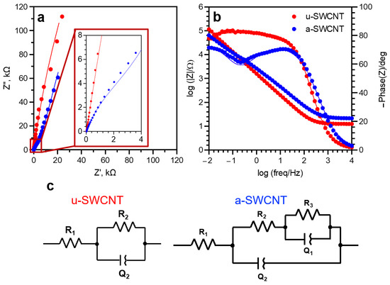
Figure 5.
Nyquist (a) and Bode (b) plot of SWCNTs samples in 5 M LiNO3 with appropriate equivalent circuits (c).
The cyclic voltammogram of SWCNTs networks in 5 M LiNO3 at the scan rate 0.5 mV s−1 (Figure 6) clearly shows the peaks of Li+ intercalation (−0.02 V vs. Ag/AgCl) and deintercalation (0.04 V vs. Ag/AgCl) according to reactions (1) and (2) [54,55].
Intercalation xLi+ + xe− + C → LixC
Deintercalation LixC → xLi+ + xe− + C
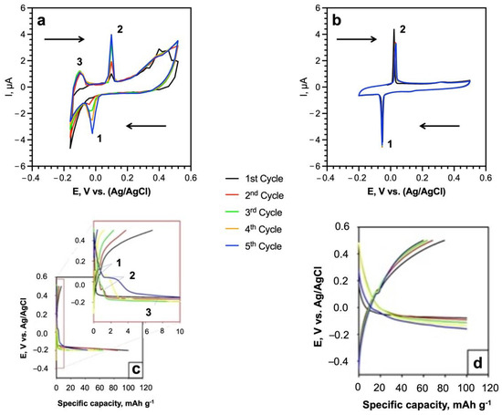
Figure 6.
(a,b) Cyclic voltammograms in 5 M LiNO3 of SWCNTs anodes: (a) u-SWCNT and (b) a-SWCNT at the scan rate of 0.5 mV s−1 (c,d) charge/discharge plateaus of the first five cycles of u-SWCNT (c), and a-SWCNT (d) in the 5 M LiNO3 at the C rate of 0.5 C. The arrows on the plots (a,b) indicate the potential scan.
The intercalation and deintercalation processes of Li+ ions demonstrate high reversibility, confirmed by the reproducibility of the voltammogram peaks in all 5 CV cycles (Figure 6). During the first cycle, lithium intercalation leads to a short-time excess of positive charge on the electrode surface [56]. At the same time, NO3− and OH− anions are concentrated around the electrode to reduce this positive charge. The formed electric double layer at the electrode/solution interface creates additional restrictions for Li+ deintercalation. During the first five cycles, the amount of intercalated lithium in SWCNT increases, which leads to the strengthening in the electrostatic adsorption of anions and is supported by the rising in the height of the intercalation and deintercalation peaks on the voltammogram (Figure 6, peak 1 and peak 2, respectively); this effect is more pronounced for the u-SWCNT (Figure 6a).
The group of carboxylates, which are present in u-SWCNT as weakly electron-withdrawing ligands, could act as redox centers for coordination with Li [57], and the presence of the third peak III (−0.16 V vs. Ag/AgCl) (Figure 6a) can be associated with the interaction of surface carboxyl groups with lithium ions:
xLi+ + nRCOOH → nLix(COOR) + nH+
The charge/discharge potential plateaus (Figure 6c,d) in the initial five cycles are in good agreement with the CV results (Figure 6a,b). Both samples (u-SWCNT, a-SWCNT) demonstrated small plateaus which represent the Li+ intercalation and deintercalation processes (Figure 6a,b). For the u-SWCNT sample, the additional charge plateau was observed as well at −0.16 V vs. Ag/AgCl indicating the reaction between surface carboxyl groups with lithium ions.
The total stored charge resulting from both faradaic and non-faradaic processes was determined from the area beneath the CV curves obtained at different sweep rates (Figure 7a,b), as described in our previous works [41,42]. While a significant contribution of the capacitive current can be observed for both samples, the contribution of the diffusion-controlled Li+ intercalation effect for a-SWCNT increases by 7–10% compared to u-SWCNT (Figure 7c,d), which may indicate the removal of diffusion restrictions for lithium intercalation after annealing.
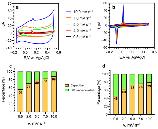
Figure 7.
Cyclic voltammetry curves at different sweep rates for u-SWCNT (a) and a-SWCNT. (b) and the contribution ratio of capacitive and diffusion-controlled current at different scan rates for u-SWCNT (c) and a-SWCNT (d).
The cycling performance of the u-SWCNT anode at 0.5 C in 5 M LiNO3 showed very low specific capacity values (Figure 8a). The initial discharge capacity (6.5 mAh g−1) was significantly lower than the charge capacity (100 mAh g−1) showing the Coulombic efficiency of only 6.5%. During cycling, the Coulombic efficiency gradually increased due to a significant reduction in charging capacity and reached 30% by the 100th cycle. Irreversible capacity is most likely associated with the irreversible reaction between lithium and -COO- groups of SWCNT [58,59], which is also supported by the cyclic voltammetry (Figure 6a) and FTIR data (Figure 3).
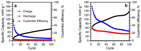
Figure 8.
Cycling performances of u-SWCNT (a) and a-SWCNT (b) anodes at 0.5C in 5 M LiNO3.
The annealing of the electrode made it possible to increase the initial value of the discharge capacity by 10 times compared to the unannealed sample (65 mAh g−1 for a-SWCNT and 6.5 mAh g−1 for u-SWCNT). The value of the initial charging capacity also increased to 170 mAh g−1, while the initial Coulombic efficiency for the a-SWCNT sample was ~30% with a gradual increase during cycling to ~70% (Figure 8b), which may be due to the dissolved-in-electrolyte oxygen reduction at the platinum counter electrode [60]. During the cycling of the a-SWCNT anode, the discharge capacity gradually decreased and by the 100th cycle was 33 mAh g−1.
The low value of the Coulombic efficiency (for u-SWCNT <15% and for a-SWCNT <30%) can be caused due to the reduction of oxygen at the platinum counter electrode. The main sources of oxygen are the electrolyte (dissolved oxygen) and SWCNT (adsorbed oxygen). In the following cycling (from the 20th to the 100th cycle), the capacities start to stabilize which is indicated by a gradual increment of Coulombic efficiency. This fact might indicate that in the subsequent cycling, the amount of dissolved oxygen in the electrolyte has significantly decreased. In addition, the significant capacity fading in the first cycles is very common for the aqueous type of LIBs [28,61].
The reasons for such a 10-fold increase in the capacity of a-SWCNT compared to the u-SWCNT sample can be explained by the formations of some nanowindows on the graphene sheets after annealing, as evidenced by the obtained impedance spectrum (Figure 5). For a better understanding of the processes of charge accumulation in u-SWCNT and a-SWCNT samples during cycling, impedance spectra and the equivalent circuits were obtained for the anodes in discharged states (Figure 9).
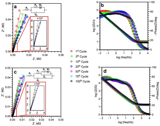
Figure 9.
Nyquist (a,c) and Bode (b,d) plots for u-SWCNT (a,b) and a-SWCNT (c,d) anodes during cycling in 5 M LiNO3.
The R1 value, which indicates the electrolyte resistance, is relatively stable during cycling, indicating the good performance/stability of the electrolyte (Figure 9, Table 2). For both samples, the charge transfer resistance (R2), which represents the resistance of the electrical double layer, decreases during cycling for both samples—five times for the u-SWCNT sample and six times for the a-SWCNT sample. Both samples have a Warburg element, that describes the diffusion of solvated ions from the solution volume to the electrode surface. For both samples, the R2 and W1 values decrease during cycling, indicating the acceleration of the electrochemical charge transfer reactions and the removal of limiting restrictions for lithium intercalation with subsequent cycles. R3 and Q1 elements for the a-SWCNT sample represent pore resistance and capacitance, respectively. The calculated parameters of the a-SWCNT electrode impedance (Table 2) made it possible to conclude that lithium intercalates in the inhomogeneity of the electrode already in the first cycle, during which the Q1 increases from 0.8 × 10⁻⁴ to 1.1 × 10⁻⁴ Ω·s−n, and practically does not change during cycling. Lithium diffusion decreases during continuous cycling, as evidenced by the decrease in the Warburg impedance values from 27.1 × 10⁶ to 0.2 × 10⁶ Ω·s−1/2. The main changes are observed in the structure of the electrical double layer: the resistance R2 decreases from 1200 Ω after the first cycle to 200 Ω after the 100th cycle, as well as a decrease in the parameter Q2 from 2.4 × 10⁻⁴ to 0.9 × 10⁻⁴ Ω·s−n, respectively. Based on these data, it can be concluded that an increase in the porosity of the electrode is one of the reasons for the increase in the capacitance of the electrode.
Table 2.
Results of simulation of electrode impedance during cycling of untreated and annealed SWCNT anodes.
3.3. Changes in Surface Morphology and Material Structure of SWCNTs Samples during Cycling as an Anode in 5M LiNO3
After 5 cycles, no change is observed for the a-SWCNT sample (Figure 2e); however, in the case of u-SWCNT, the sample is partially covered with crystals (predominantly LiNO3). This difference is due to the fact that lithium interacts with -COOH groups of u-SWCNT already during the first cycles, thus staying on the electrode surface and forming nucleation centers around which crystals can start to form. After 100 cycles, the crystal structures cover the whole surface of the u-SWCNT electrode (Figure 2c). For the annealed sample, crystals are also formed on the surface; however, they are dispersed along the entire length of the nanotubes and do not cover the entire surface (Figure 2f). The SEM (Figure 2) and EDX data (Supplementary Figures S1–S8) did not reveal any structural changes for the u-SWCNT and a-SWCNT electrodes after cycling. Additionally, the before and after cycling XRD pattern (Figure 10) for the SWCNT on the glass substrate showed that the sample is amorphous—no significant diffraction peaks were identified, except for a broad, low intensity band with a Bragg angle at 2θ between 20 and 30° (Figure 8). This indicates that material is amorphous and the XRD signal most likely is a sum of the SWCNT electrode and the glass substrate. After cycling (100 cycles), there were no significant changes in the XRD pattern.
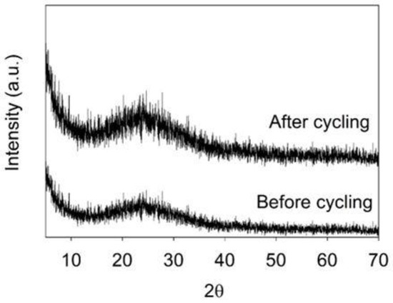
Figure 10.
X-ray diffraction patterns of the SWCNT networks on the glass substrate before and after 100 charge/discharge cycles.
Accompanied with the cycling performance data, it can be concluded, that the formation of the crystals around the a-SWCNT pores, possibly created by the removal of -COOH, inhibits the intercalation/deintercalation of lithium in SWCNT by a lesser extent than the one for the untreated sample, thus improving the overall electrochemical performance.
4. Conclusions
The electrochemical properties of untreated and reduced SWCNTs were investigated. The mechanism of interaction between an aqueous solution of 5M LiNO3 and the untreated SWCNT anode is a complex multistep process, where the intercalation/deintercalation of lithium into single-walled carbon nanotubes is complicated by unwanted side-reactions of lithium cations with -COOH groups on SWCNTs. They lead to the gradual crystallization of lithium nitrate from the solution on the surface of the SWCNT network anode. These parallel processes are responsible for the low discharge capacity (3 mAh g−1 after 100 cycles) and low value of the Coulombic efficiency (30% after 100 cycles). The annealing of SWCNTs in a hydrogen atmosphere significantly improved the characteristics of the anode in a water-based 5 M LiNO3 electrolyte. Compared to the untreated sample, the Coulombic efficiency for the annealed sample after 100 cycles increased more than two times to 70%, and the anode discharge capacity increased by a factor of 10—to 33 mAh g−1. This increase in the performance is associated with the removal of -COOH groups from the SWCNTs surface, which eliminates the undesirable side reactions, alters the crystallization mechanism of the lithium nitrate on the anode’s surface, and creates additional pores on the surfaces of SWCNTs, allowing lithium to intercalate/deintercalate more effectively.
These findings are important for both the use of SWCNTs as standalone anodes and even more so as electroconductive and structural additives to other active materials.
Supplementary Materials
The following supporting information can be downloaded at: https://www.mdpi.com/article/10.3390/batteries9050260/s1, Figure S1. EDX spectra of the untreated SWCNT (u-SWCNT) sample before cycling. Figure S2. EDX spectra of the untreated SWCNT (u-SWCNT) sample after 100 cycles. Figure S3. EDX spectra of the annealed SWCNT (a-SWCNT) sample before cycling. Figure S4. EDX spectra of the annealed SWCNT (a-SWCNT) sample after 100 cycles. Figure S5. EDX mapping spectra of the untreated SWCNT (u-SWCNT) sample before cycling. Figure S6. EDX mapping spectra of the untreated SWCNT (u-SWCNT) sample after 100 cycles. Figure S7. EDX mapping spectra of the annealed SWCNT (a-SWCNT) sample before cycling. Figure S8. EDX mapping spectra of the annealed SWCNT (a-SWCNT) sample after 100 cycles.
Author Contributions
Conceptualization, Y.R. and D.E.; methodolgy, Y.R., R.M. and J.A.; validation, J.S.; formal analysis, Y.R.; investigation, Y.R., R.M. and V.L.; resources, J.S. and D.E., data curation, J.A., writing—original draft preparation, Y.R.; writing—review and editing, Y.R., R.M., V.L. and D.E.; visualisation, V.L.; supervision, D.E.; project administration, Y.R. and D.E.; funding acquisition, D.E. and Y.R. All authors have read and agreed to the published version of the manuscript.
Funding
This research was funded by European Regional Development Fund Project (ERDF) No. 1.1.1.1/19/A/139, Y.R. thanks for the support of the post-doctoral ERDF project No. 1.1.1.2/VIAA/4/20/694.
Data Availability Statement
Data are available, contacting corresponding author via-email.
Acknowledgments
The authors would like to thank Vanda Voikiva and Andrei Felsharuk for their help with the electrode preparation and Artis Kons for his help in obtaining the XRD data.
Conflicts of Interest
The authors declare no conflict of interest.
References
- Kato, H.; Yamamoto, Y.; Nagamine, M.; Nishi, Y. Lithium ion rechargeable batteries. In Proceedings of the WESCON ′93, San Francisco, CA, USA, 28–30 September 1993; Volume 51, pp. 210–214. [Google Scholar] [CrossRef]
- Fergus, J.W. Recent developments in cathode materials for lithium ion batteries. J. Power Sources 2010, 195, 939–954. [Google Scholar] [CrossRef]
- Mekonnen, Y.; Sundararajan, A.; Sarwat, A.I. A review of cathode and anode materials for lithium-ion batteries. In Proceedings of the SoutheastCon 2016, Norfolk, VA, USA, 30 March–3 April 2016; pp. 1–6. [Google Scholar]
- Wang, Y.; Cao, G. Developments in Nanostructured Cathode Materials for High-Performance Lithium-Ion Batteries. Adv. Mater. 2008, 20, 2251–2269. [Google Scholar] [CrossRef]
- Liu, J.; Li, X.; Wang, Z.; Guo, H.; Peng, W.; Zhang, Y.; Hu, Q. Preparation and characterization of lithium hexafluorophosphate for lithium-ion battery electrolyte. Trans. Nonferrous Met. Soc. China 2010, 20, 344–348. [Google Scholar] [CrossRef]
- Plichta, E.J.; Behl, W.K. Low-temperature electrolyte for lithium and lithium-ion batteries. J. Power Sources 2000, 88, 192–196. [Google Scholar] [CrossRef]
- Zhang, S.S.; Jow, T.R.; Amine, K.; Henriksen, G.L. LiPF6-EC-EMC electrolyte for Li-ion battery. J. Power Sources 2002, 107, 18–23. [Google Scholar] [CrossRef]
- Wang, Y.; Zhong, W.H. Development of electrolytes towards achieving safe and high-performance energy-storage devices: A review. ChemElectroChem 2015, 2, 22–36. [Google Scholar] [CrossRef]
- Xu, K. Nonaqueous Liquid Electrolytes for Lithium-Based Rechargeable Batteries. Chem. Rev. 2004, 104, 4303–4418. [Google Scholar] [CrossRef]
- Cresce, A.; Xu, K. Aqueous lithium-ion batteries. Carbon Energy 2021, 3, 721–751. [Google Scholar] [CrossRef]
- Yang, H.; Zhuang, G.V.; Ross, P.N. Thermal stability of LiPF6 salt and Li-ion battery electrolytes containing LiPF6. J. Power Sources 2006, 161, 573–579. [Google Scholar] [CrossRef]
- Kawamura, T.; Okada, S.; Yamaki, J.I. Decomposition reaction of LiPF6-based electrolytes for lithium ion cells. J. Power Sources 2006, 156, 547–554. [Google Scholar] [CrossRef]
- Zinigrad, E.; Larush-Asraf, L.; Gnanaraj, J.S.; Sprecher, M.; Aurbach, D. On the thermal stability of LiPF6. Thermochim. Acta 2005, 438, 184–191. [Google Scholar] [CrossRef]
- Sloop, S.E.; Pugh, J.K.; Wang, S.; Kerr, J.B.; Kinoshita, K. Chemical reactivity of PF5 and LiPF6 in ethylene carbonate/dimethyl carbonate solutions. Electrochem. Solid-State Lett. 2001, 4, 42–44. [Google Scholar] [CrossRef]
- Heider, U.; Oesten, R.; Jungnitz, M. Challenge in manufacturing electrolyte solutions for lithium and lithium ion batteries quality control and minimizing contamination level. J. Power Sources 1999, 81–82, 119–122. [Google Scholar] [CrossRef]
- Tasaki, K.; Kanda, K.; Nakamura, S.; Ue, M. Decomposition of LiPF[sub 6] and Stability of PF[sub 5] in Li-Ion Battery Electrolytes. J. Electrochem. Soc. 2003, 150, A1628. [Google Scholar] [CrossRef]
- Plakhotnyk, A.V.; Ernst, L.; Schmutzler, R. Hydrolysis in the system LiPF6—Propylene carbonate—Dimethyl carbonate—H2O. J. Fluor. Chem. 2005, 126, 27–31. [Google Scholar] [CrossRef]
- Li, W.; McKinnon, W.R.; Dahn, J.R. Lithium Intercalation from Aqueous Solutions. J. Electrochem. Soc. 1994, 141, 2310–2316. [Google Scholar] [CrossRef]
- Li, W.; Dahn, J.R.; Wainwright, D.S. Rechargeable Lithium Batteries with Aqueous Electrolytes. Science 1994, 264, 1115–1118. [Google Scholar] [CrossRef]
- Wessells, C.; Ruff, R.; Huggins, R.A.; Cui, Y. Investigations of the electrochemical stability of aqueous electrolytes for lithium battery applications. Electrochem. Solid-State Lett. 2010, 13, 2010–2013. [Google Scholar] [CrossRef]
- Hou, Y.; Wang, X.; Zhu, Y.; Hu, C.; Chang, Z.; Wu, Y.; Holze, R. Macroporous LiFePO4 as a cathode for an aqueous rechargeable lithium battery of high energy density. J. Mater. Chem. A 2013, 1, 14713–14718. [Google Scholar] [CrossRef]
- Qu, Q.; Fu, L.; Zhan, X.; Samuelis, D.; Maier, J.; Li, L.; Tian, S.; Li, Z.; Wu, Y. Porous LiMn2O4 as cathode material with high power and excellent cycling for aqueous rechargeable lithium batteries. Energy Environ. Sci. 2011, 4, 3985. [Google Scholar] [CrossRef]
- Wang, Y.; Yi, J.; Xia, Y. Recent Progress in Aqueous Lithium-Ion Batteries. Adv. Energy Mater. 2012, 2, 830–840. [Google Scholar] [CrossRef]
- Luo, J.Y.; Cui, W.J.; He, P.; Xia, Y.Y. Raising the cycling stability of aqueous lithium-ion batteries by eliminating oxygen in the electrolyte. Nat. Chem. 2010, 2, 760–765. [Google Scholar] [CrossRef] [PubMed]
- Zhang, M.; Dahn, J.R. Electrochemical Lithium Intercalation in VO2(B) in Aqueous Electrolytes. J. Electrochem. Soc. 1996, 143, 2730–2735. [Google Scholar] [CrossRef]
- Köhler, J.; Makihara, H.; Uegaito, H.; Inoue, H.; Toki, M. LiV3O8: Characterization as anode material for an aqueous rechargeable Li-ion battery system. Electrochim. Acta 2000, 46, 59–65. [Google Scholar] [CrossRef]
- Wang, G.X.; Zhong, S.; Bradhurst, D.H.; Dou, S.X.; Liu, H.K. Secondary aqueous lithium-ion batteries with spinel anodes and cathodes. J. Power Sources 1998, 74, 198–201. [Google Scholar] [CrossRef]
- Wang, H.; Huang, K.; Zeng, Y.; Yang, S.; Chen, L. Electrochemical properties of TiP2O7 and LiTi2(PO4)3 as anode material for lithium ion battery with aqueous solution electrolyte. Electrochim. Acta 2007, 52, 3280–3285. [Google Scholar] [CrossRef]
- Wang, H.; Huang, K.; Ren, Y.; Huang, X.; Liu, S.; Wang, W. NH4V3O8/carbon nanotubes composite cathode material with high capacity and good rate capability. J. Power Sources 2011, 196, 9786–9791. [Google Scholar] [CrossRef]
- He, Z.; Jiang, Y.; Sun, D.; Dai, L.; Wang, H. Advanced LiTi2(PO4)3/C anode by incorporation of carbon nanotubes for aqueous lithium-ion batteries. Ionics 2017, 23, 575–583. [Google Scholar] [CrossRef]
- Huang, X.; Li, X.; Wang, H.; Pan, Z.; Qu, M.; Yu, Z. Synthesis and electrochemical performance of Li2FeSiO4/carbon/carbon nano-tubes for lithium ion battery. Electrochim. Acta 2010, 55, 7362–7366. [Google Scholar] [CrossRef]
- Duan, W.; Zhao, M.; Mizuta, Y.; Li, Y.; Xu, T.; Wang, F.; Moriga, T.; Song, X. Superior electrochemical performance of a novel LiFePO4/C/CNTs composite for aqueous rechargeable lithium-ion batteries. Phys. Chem. Chem. Phys. 2020, 22, 1953–1962. [Google Scholar] [CrossRef]
- Barraza-Fierro, J.I.; Chiu, T.M.; Castaneda, H. Electrochemical impedance characterization of LiMnPO4 electrodes with different additions of MWCNTs in an aqueous electrolyte. J. Mex. Chem. Soc. 2019, 63, 39–55. [Google Scholar] [CrossRef]
- Smith, M.R.; Hedges, S.W.; LaCount, R.; Kern, D.; Shah, N.; Huffman, G.P.; Bockrath, B. Selective oxidation of single-walled carbon nanotubes using carbon dioxide. Carbon N. Y. 2003, 41, 1221–1230. [Google Scholar] [CrossRef]
- Jo, A.; Lee, B.; Kim, B.G.; Lim, H.; Han, J.T.; Jeong, S.Y.; Kim, J.; Seo, S.H.; Jeong, H.J.; Lee, G.-W.; et al. Ultrafast Laser Micromachining of Hard Carbon Anodes for High-Performance Sodium-Ion Capacitors. SSRN Electron. J. 2022. [Google Scholar] [CrossRef]
- Jo, A.; Lee, B.; Kim, B.G.; Lim, H.; Han, J.T.; Jeong, S.Y.; Kim, J.; Seo, S.H.; Jeong, H.J.; Lee, G.W.; et al. Ultrafast laser micromachining of hard carbon/fumed silica anodes for high-performance sodium-ion capacitors. Carbon N. Y. 2023, 201, 549–560. [Google Scholar] [CrossRef]
- Kharlamova, M.V.; Burdanova, M.G.; Paukov, M.I.; Kramberger, C. Synthesis, Sorting, and Applications of Single-Chirality Single-Walled Carbon Nanotubes. Materials 2022, 15, 5898. [Google Scholar] [CrossRef]
- Park, J.H.; Lee, H.J.; Cho, J.Y.; Jeong, S.; Kim, H.Y.; Kim, J.H.; Seo, S.H.; Jeong, H.J.; Jeong, S.Y.; Lee, G.-W.; et al. Highly Exfoliated and Functionalized Single-Walled Carbon Nanotubes as Fast-Charging, High-Capacity Cathodes for Rechargeable Lithium-Ion Batteries. ACS Appl. Mater. Interfaces 2020, 12, 1322–1329. [Google Scholar] [CrossRef]
- Buks, K.; Andzane, J.; Smits, K.; Zicans, J.; Bitenieks, J.; Zarins, A.; Erts, D. Growth mechanisms and related thermoelectric properties of innovative hybrid networks fabricated by direct deposition of Bi2Se3 and Sb2Te3 on multiwalled carbon nanotubes. Mater. Today Energy 2020, 18, 100526. [Google Scholar] [CrossRef]
- Silverstein, R.M.; Webster, F.X.; Kiemle, D. Spectrometric Identification of Organic Compounds, 7th ed.; John Wiley and Sons, Inc.: New York, NY, USA, 2005. [Google Scholar]
- Lazarenko, V.; Rublova, Y.; Meija, R.; Andzane, J.; Voikiva, V.; Kons, A.; Sarakovskis, A.; Viksna, A.; Erts, D. Bi2Se3 Nanostructured Thin films as Perspective Anodes for Aqueous Rechargeable Lithium-Ion Batteries. Batteries 2022, 8, 144. [Google Scholar] [CrossRef]
- Meija, R.; Lazarenko, V.; Skrastina, A.; Rublova, Y.; Andzane, J.; Voikiva, V.; Viksna, A.; Erts, D. The Electrochemical Characterization of Nanostructured Bi2Se3 Thin Films in an Aqueous Na Electrolyte. Batteries 2022, 8, 25. [Google Scholar] [CrossRef]
- Grundmann, M. Kramers–Kronig Relations. In The Physics of Semiconductors: An Introduction Including Nanophysics and Applications; Springer: Berlin/Heidelberg, Germany, 2010; Volume 1, pp. 775–776. ISBN 9783642138843. [Google Scholar]
- Bellamy, L.J. The Infrared Spectra of Complex Molecules; Springer Netherlands: Dordrecht, The Netherlands, 1980; Volume 216, ISBN 978-94-011-6522-8. [Google Scholar]
- Yakymchuk, O.M.; Perepelytsina, O.M.; Rud, A.D.; Kirian, I.M.; Sydorenko, M.V. Impact of carbon nanomaterials on the formation of multicellular spheroids by tumor cells. Phys. Status Solidi 2014, 211, 2778–2784. [Google Scholar] [CrossRef]
- Yakymchuk, O.M.; Perepelytsina, O.M.; Dobrydnev, A.V.; Sydorenko, M.V. Effect of single-walled carbon nanotubes on tumor cells viability and formation of multicellular tumor spheroids. Nanoscale Res. Lett. 2015, 10, 150. [Google Scholar] [CrossRef] [PubMed]
- Rémazeilles, C.; Refait, P. Fe(II) hydroxycarbonate Fe2(OH)2CO3 (chukanovite) as iron corrosion product: Synthesis and study by Fourier Transform Infrared Spectroscopy. Polyhedron 2009, 28, 749–756. [Google Scholar] [CrossRef]
- Zhang, S.; Shao, T.; Kose, H.S.; Karanfil, T. Adsorption of Aromatic Compounds by Carbonaceous Adsorbents: A Comparative Study on Granular Activated Carbon, Activated Carbon Fiber, and Carbon Nanotubes. Environ. Sci. Technol. 2010, 44, 6377–6383. [Google Scholar] [CrossRef] [PubMed]
- Ke, X.; Liang, Y.; Ou, L.; Liu, H.; Chen, Y.; Wu, W.; Cheng, Y.; Guo, Z.; Lai, Y.; Liu, P.; et al. Surface engineering of commercial Ni foams for stable Li metal anodes. Energy Storage Mater. 2019, 23, 547–555. [Google Scholar] [CrossRef]
- Liu, G.; Wang, N.; Qi, F.; Lu, X.; Liang, Y.; Sun, Z. Novel Ni–Ge–P anodes for lithium-ion batteries with enhanced reversibility and reduced redox potential. Inorg. Chem. Front. 2023, 10, 699–711. [Google Scholar] [CrossRef]
- Cho, Y.; Lee, K.S.; Piao, S.; Kim, T.-G.; Kang, S.-K.; Park, S.Y.; Yoo, K.; Piao, Y. Wrapping silicon microparticles by using well-dispersed single-walled carbon nanotubes for the preparation of high-performance lithium-ion battery anode. RSC Adv. 2023, 13, 4656–4668. [Google Scholar] [CrossRef]
- Liu, G.; Yang, Y.; Lu, X.; Qi, F.; Liang, Y.; Trukhanov, A.; Wu, Y.; Sun, Z.; Lu, X. Fully Active Bimetallic Phosphide Zn 0.5 Ge 0.5 P: A Novel High-Performance Anode for Na-Ion Batteries Coupled with Diglyme-Based Electrolyte. ACS Appl. Mater. Interfaces 2022, 14, 31803–31813. [Google Scholar] [CrossRef]
- Bruce, P.G.; Saidi, M.Y. The mechanism of electrointercalation. J. Electroanal. Chem. 1992, 322, 93–105. [Google Scholar] [CrossRef]
- Zhao, J.; Buldum, A.; Han, J.; Lu, J.P. First-principles study of Li-intercalated carbon nanotube ropes. Phys. Rev. Lett. 2000, 85, 1706–1709. [Google Scholar] [CrossRef]
- Collins, J.; Gourdin, G.; Foster, M.; Qu, D. Carbon surface functionalities and SEI formation during Li intercalation. Carbon N. Y. 2015, 92, 193–244. [Google Scholar] [CrossRef]
- Dinkelacker, F.; Marzak, P.; Yun, J.; Liang, Y.; Bandarenka, A.S. Multistage Mechanism of Lithium Intercalation into Graphite Anodes in the Presence of the Solid Electrolyte Interface. ACS Appl. Mater. Interfaces 2018, 10, 14063–14069. [Google Scholar] [CrossRef]
- Armand, M.; Grugeon, S.; Vezin, H.; Laruelle, S.; Ribière, P.; Poizot, P.; Tarascon, J.M. Conjugated dicarboxylate anodes for Li-ion batteries. Nat. Mater. 2009, 8, 120–125. [Google Scholar] [CrossRef]
- Thauer, E.; Ottmann, A.; Schneider, P.; Möller, L.; Deeg, L.; Zeus, R.; Wilhelmi, F.; Schlestein, L.; Neef, C.; Ghunaim, R.; et al. Filled carbon nanotubes as anode materials for lithium-ion batteries. Molecules 2020, 25, 1064. [Google Scholar] [CrossRef]
- Frackowiak, E.; Béguin, F. Electrochemical storage of energy in carbon nanotubes and nanostructured carbons. Carbon N. Y. 2002, 40, 1775–1787. [Google Scholar] [CrossRef]
- Jayasankar, B.; Karan, K. O2 electrochemistry on Pt: A unified multi-step model for oxygen reduction and oxide growth. Electrochim. Acta 2018, 273, 367–378. [Google Scholar] [CrossRef]
- Hou, Z.; Zhang, L.; Chen, J.; Xiong, Y.; Zhang, X.; Qian, Y. An aqueous rechargeable lithium ion battery with long cycle life and overcharge self-protection. Mater. Chem. Front. 2021, 5, 2749–2757. [Google Scholar] [CrossRef]
Disclaimer/Publisher’s Note: The statements, opinions and data contained in all publications are solely those of the individual author(s) and contributor(s) and not of MDPI and/or the editor(s). MDPI and/or the editor(s) disclaim responsibility for any injury to people or property resulting from any ideas, methods, instructions or products referred to in the content. |
© 2023 by the authors. Licensee MDPI, Basel, Switzerland. This article is an open access article distributed under the terms and conditions of the Creative Commons Attribution (CC BY) license (https://creativecommons.org/licenses/by/4.0/).