Review

Lithium Niobate for Fast Cycling in Li-ion Batteries: Review and New Experimental Results

1
Clausthal Centre of Material Technology, Clausthal University of Technology, D-38678 Clausthal-Zellerfeld, Germany
2
Solid State Kinetics Group, Institute of Metallurgy, Clausthal University of Technology, D-38678 Clausthal-Zellerfeld, Germany
3
Laboratory for Neutron Scattering and Imaging, Paul Scherrer Institut, 5232 Villigen, Switzerland
4
Institute of Physical Chemistry and Electrochemistry, Leibniz University Hannover, D-30167 Hannover, Germany
*
Author to whom correspondence should be addressed.
Current address: Institute for Materials Mechanics, Helmholtz-Zentrum Hereon, 21502 Geesthacht, Germany.
Batteries 2023, 9(5), 244; https://doi.org/10.3390/batteries9050244
Submission received: 28 February 2023 / Revised: 4 April 2023 / Accepted: 15 April 2023 / Published: 25 April 2023

Abstract

:
Li-Nb-O-based insertion layers between electrodes and electrolytes of Li-ion batteries (LIBs) are known to protect the electrodes and electrolytes from unwanted reactions and to enhance Li transport across interfaces. An improved operation of LIBs, including all-solid-state LIBs, is reached with Li-Nb-O-based insertion layers. This work reviews the suitability of polymorphic Li-Nb-O-based compounds (e.g., crystalline, amorphous, and mesoporous bulk materials and films produced by various methodologies) for LIB operation. The literature survey on the benefits of niobium-oxide-based materials for LIBs, and additional experimental results obtained from neutron scattering and electrochemical experiments on amorphous LiNbO3 films are the focus of the present work. Neutron reflectometry reveals a higher porosity in ion-beam sputtered amorphous LiNbO3 films (22% free volume) than in other metal oxide films such as amorphous LiAlO2 (8% free volume). The higher porosity explains the higher Li diffusivity reported in the literature for amorphous LiNbO3 films compared to other similar Li-metal oxides. The higher porosity is interpreted to be the reason for the better suitability of LiNbO3 compared to other metal oxides for improved LIB operation. New results are presented on gravimetric and volumetric capacity, potential-resolved Li+ uptake and release, pseudo-capacitive fractions, and Li diffusivities determined electrochemically during long-term cycling of LiNbO3 film electrodes with thicknesses between 14 and 150 nm. The films allow long-term cycling even for fast cycling with rates of 240C possessing reversible capacities as high as 600 mAhg−1. Electrochemical impedance spectroscopy (EIS) shows that the film atomic network is stable during cycling. The Li diffusivity estimated from the rate capability experiments is considerably lower than that obtained by EIS but coincides with that from secondary ion mass spectrometry. The mostly pseudo-capacitive behavior of the LiNbO3 films explains their ability of fast cycling. The results anticipate that amorphous LiNbO3 layers also contribute to the capacity of positive (LiNixMnyCozO2, NMC) and negative LIB electrode materials such as carbon and silicon. As an outlook, in addition to surface-engineering, the bulk-engineering of LIB electrodes may be possible with amorphous and porous LiNbO3 for fast cycling with high reversible capacity.

1. Introduction

The positive electrode of a (rechargeable) lithium-ion battery (LIB) has to (i) deliver charge (i.e., Li+ ions) for the storage process into the negative electrode during LIB operation, and (ii) possess a high electrochemical potential (e.g., 3 V) versus the negative electrode. Consequently, the electrochemically active material of the positive electrode has to be of different chemistry to that of the negative electrode. Currently, this is realized by using Li-based metal oxides such as LiCoO2, LiNixMnyCozO2, x + y + z = 1 (NMC), and LiFePO4 as electrochemically active materials in positive electrodes (e.g., Refs. [1,2,3,4,5,6,7,8,9,10,11,12,13,14,15,16,17,18,19,20,21,22,23,24,25,26] to cite only some of the work on positive electrodes). Carbon (e.g., graphite) [27,28] and silicon [29,30] are utilized as Li+ storage media, i.e., as electroactive material for negative electrodes. Since recently, the introduction of lithium niobate (LiNbO3) in LIB is considered to boost stability (integrity) and fast operation even for high-voltage (i.e., towards 5 V) LIBs, as it is further outlined in the next section. LiNbO3 is not a new type of material. It is known for its technological importance as described in the next section. A recent application of LiNbO3 is in the field of LIBs. Li-Nb-O-based insertion layers between electrodes and electrolytes were recently found to protect electrodes and electrolytes from unwanted reactions and to enable fast Li transport over interfaces. This may result in the proper operation of high-voltage and high-energy-density LIBs, including all-solid-state LIBs. This work reviews the benefits of niobium-oxide-based materials and presents additional results obtained from neutron scattering and electrochemical experiments.
This work is organized as follows. Section 2 gives a literature review of Li-Nb-O-based materials for fast cycling in LIBs with a focus on LiNbO3. The reason for the LIB cycling improvement by lithium niobate will be addressed. The review is divided into four subsections. Section 2.1 summarizes some basics about lithium niobate. Section 2.2 gives an overview of lithium niobate-based electrochemically active materials for fast cycling in LIBs. Section 2.3 is focused on lithium niobate-based insertion layers at the electrolyte/electrode interface for improved LIB operation. Section 2.4 reviews the reported Li diffusivities obtained experimentally in bulk-crystalline and amorphous thin-film LiNbO3, LiTaO3, LiAlO2, and LiGaO2. The review reveals the outstanding position of amorphous thin-film LiNbO3 concerning the highest Li diffusivity.
Section 3 presents new results gained by neutron scattering and electrochemical experiments to elucidate why LiNbO3, and especially thin films thereof, improves LIB operation. The study is focused on the material characterization and the electrochemical performance of ion-beam sputter-deposited LiNbO3 films for fast cycling in LIBs. After presenting the experimental procedure (Section 3.1), the characterization of a LiNbO3 thin film by neutron reflectometry (NR) will be reported in Section 3.2. It will be shown that neutron reflectometry found a high porosity in thin-film LiNbO3, which explains the measured faster Li diffusion process in deposited LiNbO3 films. The higher free volume explains the benefit of using thin-film LiNbO3 compared to other similar Li-based metal oxide materials in LIBs. Section 3.3 presents additional electrochemical results (i) on the potential-resolved Li+ uptake and release during cycling voltammetry and constant current cycling, (ii) on pseudo-capacitive quota determination, (iii) of electrochemical impedance spectroscopy investigations, and (iv) on gravimetric capacities during long-term cycling and rate capability experiment. The results reveal that ion-beam sputter-deposited LiNbO3 films allow fast cycling. Section 3.4 contains final remarks, discusses open questions, and presents the outlook. The work is summarized in Section 4.

2. Review on Lithium Niobate for Fast Cycling in LIBs

2.1. Some Basics of Lithium Niobate

Lithium niobate (LiNbO3) crystals are stable against an air environment and possess a high melting point (congruent LiNbO3 at 1255 °C) [31,32,33,34,35,36]. They are insoluble in water and organic solvents [33]. LiNbO3 in amorphous form is resistant against crystallization up to 400 °C, as was numerously confirmed in our laboratory (e.g., see Ref. [37]). The stability of LiNbO3 may stem from the strong bond affinity of oxygen to niobium [38]. Thus, LiNbO3 may be suitable for processes where strong mechanical and organic solvent impact appears, such as in LIB operation.
The Web of Science (WoS) core collection reports to date more than 23,000 publications when the term “lithium niobate*” or “LiNbO*” is used in the search, including nearly 400 reviews. The overwhelming part of the publications are in the field of optics: WoS cites more than 21,000 publications for the term “optic” and “lithium niobate*” or “LiNbO*”, including 350 reviews. In contrast, WoS indexes only 90 publications when the terms “LiNbO*” and “lithium-ion battery” are used. The high interest in LiNbO3 in optics stems from the fact that crystalline LiNbO3 is one of the most technologically important optical materials due to its pyroelectric, piezoelectric, electro-caloric, acousto-optical, giant-photovoltaic, ferroelectric, electro-optical, photorefractive, and non-linear optical properties [31,32,33,34,35,36,39,40,41,42,43,44,45]. This revolutionizes low-power and ultra-high-speed solutions for optical communication networks and microwave photonic systems [42]. These properties are combined with the low cost of LiNbO3 production [32]. LiNbO3 has been called the “workhorse of the optoelectronic industry” [42]. LiNbO3 in the form of a thin film (400 nm film) was found to enable high-speed transmissions of a 100 Gbs−1 data rate per wavelength channel on a chip transmitter [45].
LiNbO3 single crystals are grown by the Czochralski method, see, e.g., [33], and are commercially available. LiNbO3 tends to be nonstoichiometric. In the phase diagram of the Li2O–Nb2O5 pseudo-binary system (see, e.g., [33]), LiNbO3 single crystals have a solid solution range from the stoichiometric point (50% Li2O) to 47% Li2O. The congruent composition contains 48.5% Li2O. Coarse-grained microcrystalline LiNbO3 is also commercially available. The experience in our laboratories (PH and HS) in producing nanocrystalline and amorphous LiNbO3 is as follows. Nanocrystalline LiNbO3 can be successfully prepared by grain-size reduction of microcrystalline LiNbO3 using the high-energy ball milling technique [35]. Another method is nanocrystal growth from amorphous LiNbO3 by heating treatments [36,46]. Amorphous LiNbO3 can be produced by the double alkoxide sol-gel route. This consists of irregular particles with diameters of 1–20 µm [36,47]. Amorphous thin films can be produced by sputter-deposition as described in this work. A recent article [48] describe coating methodologies of powdered LIB active materials with special emphasis on atomic layer deposition and chemical layer deposition of LiNbO3 films on NMC particles. Further synthesis processes for Li-Nb-O entities used in LIB electrodes and their morphologies are described in the next subsections, where the use of Li-Nb-O as a negative electrode active material and as a negative or positive electrode coating layer is reviewed.
The crystal structure of LiNbO3, including its defect structure (e.g., for congruent LiNbO3 [49]), is nowadays extensively studied, and reported, see Refs. [33,34,36] for examples of a book, a review, and a PhD thesis, respectively. The crystal structure of LiNbO3 is trigonal with vertical displacement of the cations from the center of the oxygen octahedra in the hexagonal c-axis (the non-centro-symmetric space group R3c and the point group 3m). It has a hexagonal-close-packed oxygen lattice with distorted octahedra sharing faces. The Nb sits near the center of the octahedra, whereas Li is positioned more off-central, resulting in a polar symmetry. The crystal structure of LiNbO3 will not be further discussed in this work, which is more focused on the amorphous phase of LiNbO3 for LIB operation. Nevertheless, the lithiation mechanism of crystalline LiNbO3 grains between conductive and binder additives represents an interesting task for future examination.

2.2. Lithium Niobate for Fast Cycling in LIBs

The influence of the atomic arrangement on the performance of Li-Nb-O-based LIB electrodes is of importance for this work. Widely used terms such as amorphous, nano-crystalline, poly-crystalline, mono-crystalline, voids, and mesoporous, will be used to discuss the particular atomic arrangements. The atomic network in amorphous materials is thought to lack long-range order. More specifically, in this work, materials are considered to be amorphous if they do not produce recognizable patterns in X-ray diffraction (XRD). Such materials are called X-ray amorphous. Note that X-ray-amorphous materials may also possess short-range order within small zones (e.g., of below 2 nm). Materials are considered to be polycrystalline if they are composed of multiple grains that are not oriented in the same direction. An example of a polycrystalline material is an electrode film material produced by drying a slurry of crystalline powder mixed with a binder and other additives. Nano-crystalline materials are poly-crystalline materials with grains below 100 nm in diameter, typically in the range from 5 to 50 nm. A single crystal is mono-crystalline. It is considered to be one (single) large crystal (e.g., a wafer). Voids are free spaces inside materials, i.e., pores. Mesoporous represents a porous material with pores in the nanometric range.
Figure 1 presents schematized cross-sections through various kinds of LIBs discussed in this work. The schematized positive electrode (called also cathode) is an oxide such as LiNixMnyCozO2 (NMC), which will often be mentioned in this review. Figure 1a shows a scheme of commercial batteries where the negative electrode (called also anode) contains graphite [27,28] as the electrochemically active material. More charge can be stored if the negative electrode encompasses silicon [29,30] (Figure 1b). Figure 1c schematically shows a LIB whose negative electrode contains various kinds of LiNbO3 entities mentioned in this review as suitable for LIB operation. These are, in particular, a combination of LiNbO3 nanoplates with carbon nanotubes [50], LiNbO3 nanoparticles [51,52] with conductive additives and binders, and porous LiNbO3 [52,53], which will be discussed in the following sections.
Li-Nb-O-based materials were found to enable fast operation in LIBs and electrochromic devices [1,2,3,4,5,6,7,8,9,10,11,12,13,14,15,16,17,18,19,20,54,55,56,57,58,59,60,61,62,63,64,65,66,67,68]. Li-Nb-O compounds [7,8,9,21,68,69,70,71,72,73,74] and niobium oxides (e.g., Nb2O5) [49,58,59,60,61,62,63,64,65,75,76,77,78] were used in solid electrolytes [6,7,8,9,10,11,12,13,14,15,58,59,71,72,73,79,80,81,82,83,84], and negative electrodes [16,21,50,51,52,53,61,62,63,64,65,70,71,72,73,74,75,76,77,78,85,86,87,88] for LIBs and electro-chromic devices [72,79,80,89,90,91]. Current improvements and perspectives in niobium-based oxides as fast-charging negative electrode material for lithium [61,62,63,64,65,78,87] and sodium [62,87] storage are outlined in recent reviews [61,62,63,64,65,87]. Niobium-based oxides are found to enable fast and safe energy storage in LIBs [65,78] and are recently considered to be suitable negative electrode materials for use in ultrafast-charging high-power LIBs [78]. During the cycling of metal oxides such as niobium-based oxides, Li is introduced into the oxide, and LixNbyOz compounds may appear in addition to the conversion reaction, which produces Li2O and nanometric metallic zones. Li-Co-O networks, similar to those of lithium oxides in niobium oxides, could overcome key drawbacks of lithium-air batteries [92]. Furthermore, LiNbO3 may be used for flexible self-charging LIBs [93,94].
Single crystalline LiNbO3 such as LiNbO3 wafers cannot be electrochemically cycled due to low electronic conductivity. Moreover, its low electronic conductivity is accompanied by an extremely low ionic (Li+) diffusivity in the range of 10−30 m2s−1 at room temperature (the values are listed in Table 1). Crystalline LiNbO3 powder may be cycled if it is mixed with conductive agents, as it is done for positive electrode materials like LiCoO2 and NMC. Otherwise, huge overpotentials appear, inhibiting Li+ storage and Li+ release. Experiments revealed the capacity and cycling stability to be dependent on the Li-Nb-O crystallite size. Li-Nb-O electrodes produced by conventional solid-state reaction and spreading a mixed slurry on a current collector [51,52] or simply by sol-gel methods [46,47] with micrometer-sized particles show low capacity (e.g., 50 mAhg−1, which is 17% of the reported theoretical maximal capacity of LiNbO3 of 402 mAhg−1 [62,63,64,87]) and poor cycling stability [50,51,52,53,70,79]. A higher capacity (e.g., 200 mAhg−1) and better cycling stability are achieved by decreasing the size of Li-Nb-O entities to the nanometer range [50,51,52,53,70,79]. Best cycling was achieved for sizes around 20 nm such as Li-Nb-O nanoplates with thicknesses of less than 20 nm [50], and 20 nm Li-Nb-O particles [51,52]. For 3D mesoporous LiNbO3 with 10 nm pores [53], a capacity of 175 mAhg−1 was found at a 2C rate after 200 cycles in the potential window 1–3 V. In all cases, the improved cycling stability and enhanced capacity are attributed to the lower diffusion distance that electrons and Li+-ions have to travel in the nanosized LiNbO3 particles and nanosized Li-Nb-O compound walls in the case of mesoporous Li-Nb-O materials. So, in contrast to the application of LiNbO3 in optical technology where large LiNbO3 crystals are of importance, Li-Nb-O compounds with a lot of defects and nanometer-sized entities (nanoparticles, nanoplates, mesoporous materials) are of interest for LIBs. Accordingly, in this work, in addition to the literature survey, the electrochemical performance of nanometric thin films of amorphous mesoporous LiNbO3 as active materials for LIB electrodes is also investigated in Section 3.
The microwave-induced auto-combustion synthesis of 3D macroporous crystalline LiNbO3 hybrids was shown to deliver a higher capacity than commercial Li4Ti5O12 anodes [53] because Li+ and electron transport in such textured LiNbO3 materials is expected to be enhanced [53]. The utilization of an amorphous or nanocrystalline instead of a single crystalline network may enhance conductivity [46,47,79,95,96,97,98,99,100]. The work of Glass et al. [79] was the first work that showed a huge increase in the ionic conductivity in LiNbO3 glass compared to LiNbO3 crystal. In this glass, obtained by rapid quenching, the electronic conductivity is said to be negligible. Analogous results were found for LiNbO3 glass synthetized by a sol-gel process [46,47,95,96]. The enhancement in nanocrystalline LiNbO3, produced by high-energy ball-milling, was first studied in Refs. [97,98]. It proved to be similar to that in glassy LiNbO3 [46,47,95,96]. The high ionic conductivity may stem from transport via grain boundaries where a highly defective or amorphous structure is present, similar to the case of a glassy network. The amorphous network produced by other methods, e.g., by sputter-deposition, may also enhance electronic conductivity. Indeed, a recent investigation on the transport properties of magnetron sputter-deposited Li-Nb-O films onto silicon wafers found that (i) the films are amorphous [99,100], (ii) ferroelectricity is present [99], and (iii) the conductivity is governed by the electrons [100]. This is consistent with the secondary ion mass spectrometry (SIMS) experiments performed in our laboratory with O2+ primary ion beams on crystalline and amorphous LiNbO3. These results show charging during SIMS on crystalline LiNbO3, but an absence of charging for amorphous LiNbO3 films, indicating good electronic conductivity for the amorphous material. The amorphous network may enhance the electronic conductivity by defect states. Temperature-dependent nuclear magnetic resonance (NMR) spectroscopy investigations of lithiated niobium-oxide polymorphs suggest the presence of delocalized conduction electrons [55]. There, the higher lithium content obtained upon lithiation may destroy the original lattice, resulting in an amorphous network.
The following advantages of Nb-based oxide electrodes can be elaborated from the literature (e.g., Refs. [64,87]): (i) high thermodynamic stability and electrochemical reversibility for LIB operation, (ii) Li-intercalation charge storage mechanism, (iii) inexpensive Nb-based oxides synthesis, (iv) high theoretical capacity up to 403 mAhg−1 due to the multivalent state of niobium atoms, (v) good rate capability due to relatively large atomic bond distances, (vi) assumed very low volume change during cycling, (vii) working voltages higher than 1 V vs. Li-metal reference, enabling LIB operation without excessive side reactions such as electrolyte decomposition [64] or dendrite growth, and (viii) good ionic and electronic conductivity in an amorphous network. From this point of view, niobium-based oxides are claimed to represent promising anodes to replace Li4Ti5O12 (because their theoretical capacity is more than twice that of Li4Ti5O12) and graphite (because they operate at a safer potential (i.e., above 1.0 V) than graphite (≈0.1 V vs. Li-metal reference) [87]). Note, however, that LiNbO3 also has disadvantages. The operation voltage of a LiNbO3 cell is lower than that of a Li metal cell or even a silicon [29,30] or graphite [27,28] cell. This reduces the cell energy density and power level of the cell. A further disadvantage of LiNbO3 is that Nb is less abundant than silicon and carbon, and more expensive than other metals [101,102]. Due to this, there are attempts to use metal doped-niobium oxide such as BaNb3.6O10 [102] and AlNbO4 [103]. However, the main interest in Nb-based oxides for LIB operation is due to an aspect where Li+ storage in LiNbO3 has no primary importance. Thin films of LiNbO3, e.g., with thicknesses around 15 nm [18] located between the electrolyte (liquid or solid) and electrode, were found to be beneficial for LIB operation. This means that the capacity determination of the LiNbO3 films was not important and therefore not performed.

2.3. Lithium Niobate-Based Insertion Layers at the Electrolyte/Electrode Interface for Improved LIB Operation

Figure 2 presents schematized cross-sections through various kinds of LIBs discussed in this work, where LiNbO3 insertion layers are between the positive electrode and the electrolyte (Figure 2a,d) and between the negative electrode and the electrolyte (Figure 2b–d). Note that one future research direction would be to examine LIBs where LiNbO3 insertion layers are at both electrolyte surfaces, i.e., on the interface between the electrolyte and negative electrode and the interface between the electrolyte and positive electrode (Figure 2d).
Mesoporous, nano-crystalline [21,50,51,52,53,58,59,60,70,74,75,84], and amorphous [1,2,3,4,5,7,8,18,67,68,79,104,105] films of LiNbO3 are thought to optimize the interface properties of solid-state LIBs towards commercial application [17,20]. LiNbO3 insertion layers between the positive electrode material and the liquid or solid electrolyte were found to increase the capacity and rate capability of high-voltage LIBs by reducing the space charge layer barrier for Li flow through the electrolyte/electrode interfaces [1,2,3,4,5,8,9,10,11,12,13,14,15,17,18,20,22,67,68,73]. Thin LiNbO3 coatings were found to (i) mitigate electrolyte reactions and the release of metal ions from the NMC electrode into the electrolyte [104,106], (ii) enhance Li diffusion, and (iii) diminish electrode polarization during LIB operation. The release of gases following the metal ion release from the electrode into the electrolyte may lead to a LIB explosion [104,106]. A recent work [106] reviews coatings for positive electrode materials, as well as the changes in electrochemical cycling between those materials with and without an applied coating.
For coatings with LiNbO3, it was found that a 9 nm thick LiNbO3 coating layer on high-voltage positive electrodes facilitates Li diffusion above 4.5 V [22], with the result of enhancing the capacity retention and reducing the hysteresis from 0.15 V to 0.10 V [23]. Cycling NMC electrodes in liquid electrolytes at a rate of 10C, revealed a capacity of 93 mAhg−1 for uncoated NMC electrodes, while the capacity enhances to 129 mAhg−1 for LiNbO3-coated NMC electrodes (Figure 3 in Ref. [23]). At a rate of 1C and after 100 cycles, the capacity for the uncoated NMC drops to ≈127 mAhg−1, whereas that of the LiNbO3 coated NMC remains at ≈175 mAhg−1 (Figure 3 in Ref. [23]). More drastic rate improvement is reported for all-solid-state LIBs and LiCoO2 positive electrodes. Ohta et al. [9] measured the influence of 1 to 30 nm thick LiNbO3 layers between LiCoO2 positive electrode and solid electrolyte on the rate capability of solid-state batteries (see Figure 3 in Ref. [9]). The amorphous network of the LiNbO3 thin films was found to be more suitable to enhance the rate capability than crystalline LiNbO3 thin films [9,73]. The best performance was observed for ≈10 nm thick LiNbO3 films. At a current density of 5 mAcm−2, the capacity of the all-solid-state LIB without a LiNbO3 insertion layer reached only ≈8 mAhg−1, whereas that with a 10 nm thick LiNbO3 insertion layer improved ten times and reached ≈80 mAhg−1 [9]. For a ≈30 nm thick LiNbO3 insertion layer the capacity remains as high as ≈75 mAhg−1 [9]. The LiNbO3-coated LiCoO2 reaches a discharge capacity of 63 mAhg−1 even at a high current density of 10 mAcm−2, which corresponds to 0.88 Ag−1 [9]. The LiNbO3 insertion layers show no change during cycling [24]. For high voltage positive electrodes, the LiNbO3 coatings improve the rate-capability by reducing detrimental space-charge layers effects [11] and protect the electrodes against unwanted chemical reactions [5,15]. A possible explanation is that the affinity of oxygen to niobium [38] bonds volatile oxygen to niobium and, in that way, to the LiNbO3/positive-electrode interface. This reduces the defect (e.g., oxygen vacancy) density and reduces oxygen gas release and CO2 formation during the delithiation of NMC cathodes [104].
Concerning the improvements of NMC positive electrodes by Li-Nb-O coatings, a further understanding can be assessed from a recently published transmission electron microscopy (TEM) investigation [25]. Electrodes based on uncoated NMC particles are found to present cracks inside and outside the NMC particles. For electrodes with Li-Nb-O-coated NMC particles, there are no cracks outside the NMC particles, only tiny cracks inside the NMC particles during cycling. The Li-Nb-O coating possesses the following two benefits (i) it maintains the bonding between the NMC particles and, as a consequence, there is no electric contact loss in the active material, and (ii) the small cracks inside the NMC particles are proper for cycling because they release strain/stress and enable volume expansion and in that manner also maintain mechanical integrity. The improvements not only strengthen the interparticle bonds but also inhibit the irreversible phase transformation of NMC into the rock-salt phase, which is related to oxygen gas release. Recently, an atomic-scale observation of oxygen release during the delithiation of NMC cathodes was reported [104]. Oxygen release is suppressed at the interface where the LiNbO3 coating layer of NMC particles is sufficiently formed [104]. The experimental results suggest that a 10 nm thick LiNbO3 coating layer suitably stops the oxygen release from an NCM333 cathode [104]. A recent work [105] reports that even thinner films, of 3 to 5 nm, amorphous LiNbO3 coatings, are adequate for cathode material cycling improvement if the coatings are uniform. This does not mean that the LiNbO3-coated NMC cathodes do not degrade [107,108]. Only the operation for higher voltages is improved by coating the NMC with LiNbO3 [107,108]. For non-coated cathodes, the degradation of sulfur-based (Li6PS5Cl) electrolyte is dominant at potentials such as 4.25 V (versus Li-reference) [107]. The LiNbO3 coating shifts the degradation in the harsh environment of higher potentials (4.55 V vs. Li reference) and at temperatures up to 100 °C [107,108]. It was found that the LiNbO3 film releases some oxygen, but still prevents the transition metals (e.g., Ni) of the positive electrode from reaching the electrolyte. The Nb atoms remain on the positive-electrode/electrolyte interface without diffusing into the positive-electrode or the electrolyte, but some oxygen released from LiNbO3 interacts with the electrolyte producing phosphates and sulfates [104,107,108].
Improved LIB operation was achieved also on the negative electrode side (Figure 2b,c). Tens of nanometers thick LiNbO3 coatings were found to enhance the performance of Li metal negative electrodes (Figure 2b) [20,24]. Thin amorphous LiNbO3 interface layers improve the interface between a garnet-type solid-state lithium-ion conductor and a Li metal anode [20]. A 120 nm thick amorphous LiNbO3 insertion layer preserves the Li metal electrode and inhibits dendrite growth for current densities up to 0.475 mAcm−2 [20]. In contrast, the solid-electrolyte/lithium-metal interface without a LiNbO3 insertion layer revealed dendrites already at 0.350 mAcm−2 [20]. For the case of liquid electrolytes, a 30 nm thick amorphous LiNbO3 coating on the Li metal negative electrodes improves LIB operation [24] by (i) isolating the Li metal from direct contact with the liquid electrolyte, which preserves the Li metal from unwanted reactions and limits SEI formation, and (ii) inhibiting the growth of Li dendrites. The metallic Li and LiNbO3-coated Li-metal negative electrodes were used together with NMC positive electrodes [24]. In contrast to the uncoated Li metal, the surface of the LiNbO3-protected Li metal remained stable [24]. At a rate of 1C and after 100 cycles, the transferred charge for the LIB with the uncoated Li-metal negative electrode drops from ~166 mAhg−1 to ~100 mAhg−1, whereas that with the LiNbO3-coated Li-metal drops less, i.e., from to ~164 mAhg−1 to ~131 mAhg−1 (Figure 4 in Ref. [24]).
Li-based oxides such as LiNbOx, LiTaOx, Li2ZrOx, Li4Ti5Ox, Li2CoOx, and LiAlO2 are the most widely studied coating materials to improve the cycling of LIB electrodes [17,87,106]. The understanding of the solid-state Li diffusion process in niobium-based oxides is thought to be important for the preparation of thick electrodes [61]. Within this class of materials, LiNbO3 appeared to be the best coating material, due apparently to good charge-transport properties in the amorphous state [17]. However, the low electron and ionic conductivity of crystalline niobium-based oxides may still hinder fast charging [87]. Therefore, reviews claim that there is a need to develop some new strategies to improve electron transfer and Li+ diffusion rates [61,87]. It was found that the formation of the LiNbO3 layers between electrodes and electrolytes should take place at low temperatures because, in that way, an amorphous state possessing high ionic conduction may be formed [73].
Electrochemical investigations of sputter-deposited amorphous Li-Nb-O-based films without intentional sample holder heating were reported for niobium pentoxide (Nb2O5) [86] and lithium niobite (LiNbO2) [88]. Note that in lithium niobite (LiNbO2), Nb possesses a lower oxidation state than in niobate. Magnetron sputter-deposited 660 nm Nb2O5 films were found to be amorphous [86]. They were cycled galvanostatically (i.e., with constant current (CC)) in a liquid carbon-based electrolyte (1 M LiPF6 salt solved in EC + DMC) between 1 V and 3 V vs. Li-metal potential [86]. Good cycling performance was reported, without discussing the lithiation mechanism. The charge inserted and extracted during cycling was reported as charge per unit area and in that way, volumetric and gravimetric capacity was not reported [86], the latter presumably because the mass density of the amorphous Nb2O5 films was not determined. Magnetron sputter-deposited 1.1 µm thick LiNbO2 films revealed good cycling performance with a reversible capacity of 150 mAhg−1 (at C/4) [88]. A Li intercalation/deintercalation process in LiNbO2 was considered to perform via (Li+ + e) + 2Li0.5NbO2 = 2LiNbO2 possessing also some 10% of conversion reaction of LiNbO2 [88].

2.4. Li Diffusivity in Li-Based Metal Oxides

This section presents a comparison of Li diffusivities reported in the literature for single crystals and amorphous thin films of LiTaO3, LiGaO2, LiNbO3, and LiAlO2, as obtained from SIMS experiments. As mentioned before, in addition to LiNbO3, LiAlO2 coatings of cathode materials (NMC) also stabilize the interface between the positive electrode and the electrolyte, and significantly improve the rate capability [106]. The latter is attributed to the excellent Li+ conducting nature of LiAlO2 [106]. This will be examined here by comparing (i) Li diffusivities (in this section) and (ii) mass densities (porosities) obtained from NR experiments (in the next section).
The diffusivities are listed in Table 1. The Li diffusivity in LiTaO2 is similar to that in LiNbO3 for similar atomic networks (crystalline or amorphous) [109]. This is as expected due to the valence-band isoelectronic Ta and Nb. The Li diffusivity differs for the other listed materials (Table 1) and will be further discussed in Section 3.2.2.
Table 1. Li self-diffusivity in m2s−1 at room temperature determined in our laboratory for Li-based metal oxides (see [109]). The listed diffusivities for amorphous oxides are values measured at room temperature. The listed diffusivities for crystalline oxides are much lower and are extrapolated to room temperature via the Arrhenius plot of values measured at higher temperatures.
Oxide aDamorphous aDsingle-crystal bDamorphous/Dcrystal cDa-LiNbO3/Da-oxide d
LiNbO3≈1 × 10⁻¹⁸≈1 × 10⁻³⁰≈1 × 10121
LiTaO3≈8 × 10⁻¹⁹≈1 × 10⁻³⁰≈8 × 10111.25
LiAlO2≈4 × 10⁻²¹≈1 × 10⁻²⁶≈4 × 1052500
LiGaO2≈1 × 10⁻²¹≈1 × 10⁻²⁸≈1 × 10710,000
a Li diffusivity at room temperature measured in amorphous film; b Li diffusivity at room temperature extrapolated from measurements at higher temperatures in single crystal; c ratio of Li diffusivity in the amorphous and crystalline state; d ratio of Li diffusivity in amorphous LiNbO3 film and that in the other amorphous metal oxide films.
The Li diffusivity in amorphous LiNbO3 is twelve orders of magnitude larger than in crystalline LiNbO3 at room temperature (Table 1, [37,109]). This huge difference can be explained if the Li motion takes place at free surfaces inside amorphous LiNbO3. Hence, free volume (pores) may be present in amorphous LiNbO3.
The Li diffusivity in amorphous LiNbO3 (and in the heavier LiTaO2 material) at room temperature was measured to be 2500 and 10,000 times higher than that in amorphous LiAlO2 and LiGaO2, respectively (last column in Table 1), although the Li diffusivity in crystalline LiNbO3 is lower than in crystalline LiAlO2 and LiGaO2 (Table 1). This indicates that the fraction of free volume is in amorphous LiNbO3 higher than in amorphous LiAlO2 and LiGaO2. Indeed, neutron reflectometry experiments on amorphous and crystalline LiNbO3 and LiAlO2 that will be described later in this work clarify that the amorphous LiNbO3 films have a higher porosity than the other Li-metal-oxides. Further, the higher porosity in LiNbO3 is interpreted to be the reason for the mentioned higher Li mobility in amorphous LiNbO3, suitable to improve the cycling performance of LIBs. Consequently, the aim of the further experimental results presented in this work is focused on the electrochemical investigation of solely amorphous LiNbO3 in the form of single films with thicknesses between 14 and 150 nm. The investigation of the influence of the thickness may uncover bulk-like or thin-film-specific electrochemical behavior.
Li diffusivities in other Li-metal-oxides such as NMC, being measured with SIMS, are more scarce in the literature. A recent article [110] presents new insights for Li diffusion in near-stoichiometric polycrystalline and monocrystalline LiCoO2 gained by SIMS. The work provides experimental evidence of the oft-claimed sluggish lithium diffusion along the c-axis. It further indicates that for LiCoO2 the Li+ diffusion along grain boundaries is similar to bulk diffusion and does not play a dominating role in overall Li+ migration.

3. New Results Attained from Neutron Scattering and Electrochemical Experiments

3.1. Experimental Procedure

LiNbO3 and LiAlO2 films were fabricated using an ion beam coater (IBC 681) delivered by Gatan, Inc. (Pleasanton, CA, USA). The LiNbO3 thin film deposition for electrochemical investigations was performed on polished copper disks of 14 nm diameter. For NR investigations, LiNbO3 and LiAlO2 thin films were deposited on polished crystalline LiNbO3 and LiAlO2 wafers, respectively. Electrochemical investigations were performed only on LiNbO3 thin films because they possess higher porosity and higher Li diffusivity than LiAlO2 films, which are prerequisites for better cycling. This will be explained in Section 3.2.
Sputtering was accomplished by two miniature Penning ion guns aimed at the target positioned 10 cm above the sample. The LiNbO3 and LiAlO2 sputter targets were prepared as described in Ref. [37]. For LiNbO3 and LiAlO2 synthesis, the oxides Nb2O5 and Al2O3, were mixed with the carbonate Li2CO3 to enable the thermally activated reaction of Nb2O5 + Li2CO3 ⟶ 2LiNbO3 + CO2, and Al2O3 + Li2CO3 ⟶ 2LiAlO2 + CO2, respectively. Carbonates with natural Li isotope abundance (natLi2CO3 (92.6% 7Li and 7.4% 6Li), Alfa Aesar, Germany), and with 6Li isotope enriched (6Li2CO3, 96% 6Li, Eurisotop, Germany) were used to produce sputter targets with natural Li isotope abundance or with 6Li isotope enrichment. Loss of lithium appears in the film during sputter-deposition. To prevent sub-stoichiometric Li content, sputter targets with an excess of 10% Li2O were used. Ar+ (5 keV, 180 µA) ions were used for sputtering.
SIMS was performed with a CAMECA IMS-3F/4F machine (France). O2+ (5 keV, 50 nA) primary ions were used. SIMS depth profiling found a homogenous distribution of Li, Nb, and O atoms in the depth of the LiNbO3 films, except for at the very surface where the SIMS signals were higher, probably due to matrix effects, i.e., due to higher ionization cross-section on the surface.
X-ray diffraction found the sputter-deposited LiNbO3 films to be amorphous. The film thickness was determined using X-ray reflectometry (XRR) as described in Ref. [27]. Grazing incidence X-ray diffraction (GI-XRD) and XRR were measured with a Bruker D8 DISCOVER (Germany) diffractometer using Cu radiation. The sputter-deposited LiAlO2 films were also found to be amorphous.
The electrochemical investigations were done with a self-constructed three-electrode electrochemical cell. As an electrolyte, 1 M LiClO4 (Sigma Aldrich, battery grade, Darmstadt, Germany) salt was dissolved in propylene carbonate (PC, Sigma Aldrich, anhydrous, 99.7%, Germany). The cell was assembled and disassembled within an argon gas-filled glovebox with O2 and H2O contents of less than 1 ppm. Metallic lithium (1.5 mm foil, 99.9%, Alfa Aesar, Germany) was used for counter and reference electrodes. A Biologic SP150 potentiostat and the EC-lab software (BioLogic, Seyssinet-Pariset, France) were used to conduct the electrochemical experiments at room temperature. Cycling voltammetry (CV) was performed with different sweep rates. Constant current (CC) experiments were done for rate capability and long-term cycling experiments with different current densities as explained in the data presentation. Potentiostatic electrochemical impedance spectroscopy (PEIS) was performed with 10 mV amplitudes at open circuit voltage (OCV). The diameter of the lithiated zone coincides with that of the Li counter electrode and the radius of the electrolyte chamber tube (10 mm). Note that the investigated films were free of additives.
Differential charge (dQ) plots (dQ/dV) were derived from CC measurements as described in Ref. [27]. Direct comparisons between CV and dQ/dV plots are given within this work. They prove the claim that the dQ/dV and CV curves possess similar shapes if measured during the same cycle and on similar electrodes.
Reflectometry in general measures the (specular) reflected intensity of radiation of some kind from a flat surface and deduces the related density profile (as a function of the distance to the surface). The reflecting power of an interface is governed by the density contrast of the materials on both sides. Often these densities are expressed as refraction indices. While optical light probes the polarizability and X-rays the electron density, the here-used neutrons interact with the atomic nuclei, and the ‘scattering length density’ (SLD) is a measure for the averaged attraction or repulsion of the neutron by an ensemble of isotopes. The latter is important since isotopes of one element might display quite different interaction potentials (expressed as ‘scattering length’).
The ‘reflectivity curve’ is the fraction of the intensity reflected as a function of the momentum transfer qz of the incoming beam. qz = (4πsinθ)/λ is a function of the angle of incidence θ and the neutron wavelength λ. For most materials, a neutron beam hitting the surface towards air at a very small qz is totally reflected (i.e., the index of refraction is smaller than 1). Typically, the ‘angle of total reflection’ is a few tenths of a degree and it is a very precise measure of the average density of the surface. Above this critical qz, the beam penetrates the material and only a small fraction is reflected: The reflectivity curve drops with qz−4. If the penetrating fraction of the beam comes across another interface, it is again partially reflected and partially transmitted. In systems with many interfaces, quite complicated up- and down-traveling wave fields evolve (a reflected beam part might be re-reflected on an interface above). All partial waves leaving the surface interfere and the resulting measurable intensity is thus a function of all interface contrasts, of the distances in-between and of qz.
The reflectivity curve above the critical angle thus shows fringes and oscillations modulating the previously mentioned qz−4 drop. Reflectivity measurements are analyzed by comparing a calculated reflectivity based on a model of the sample to the measured one. The model essentially consists of a sequence of layers, each with an SLD and a thickness. The relation of the SLD to a chemical composition has to be based on ‘external’ knowledge and probably other techniques. An exception here is provided by the controlled variation in the isotope composition: variations in the SLD profile can then be related to this one parameter and thus to the absolute density of the respective element.
Specular neutron reflectometry probes the laterally averaged SLD, but with a depth-resolution reaching down to atomic distances. The averaging means, that no information about lateral order on a small scale or even crystallinity can be deduced.
Neutrons have a high penetration depth (several cm) in most materials (only a few isotopes are neutron absorbers) and thus can easily penetrate the ‘environment’ of the surface under investigation and they are not attenuated by the sample itself. The environment here might be the containment of an electrochemical cell or a furnace. It is thus possible to perform these measurements on an intact buried interface and even during operation as long as the surface is sufficiently flat and large. Films on wafer surfaces and functional devices based thereon are thus the ideal candidates for this method.
The NR measurements were recorded on the reflectometer Morpheus located at the Schweizer Institut für Neutronenquellen (SINQ), Paul Scherrer Institut (PSI) Villigen, Switzerland. NR simulations were performed using the Parratt32 software package [111] and the online calculator given in Ref. [112].

3.2. Determination of Mass Density, Free Volume, and Their Impact on Li Diffusivity

3.2.1. Mass Density and Free Volume

X-ray diffraction measurements found the ion-beam sputter-deposited films to be amorphous, i.e., without long-range crystalline order. The mass density can be obtained from XRR and NR. We present NR measurements because neutron scattering is isotope-sensitive allowing for contrast variation. The following analysis will refer to films with natural isotope abundance and films possessing 96% 6Li isotope enrichment. The natural abundance of the Li isotopes amounts to 92.6% 7Li and 7.4% 6Li. For reflectivity measurements, the films have to be smooth, and consequently, they are deposited on flat substrates like polished Si-wafers. However, we adopt another route and deposited amorphous Li-metal-oxide films on their respective crystals. The NR data depends on the chemical composition, the isotope abundance, and the number density of the neutron scatters (nuclei). In the case that the chemical composition and the isotope abundance do not differ between the amorphous film and the crystalline substrate, the nuclei number density is directly proportional to the mass density. In that particular case, a mass density difference between film and wafer can be observed directly in the NR data. If there is no difference in mass density between substrate and film, the reflectivity curve does not show interference fringes. Changes in the NR pattern will then directly indicate a different mass density. In that case, the existence of nano-scaled voids (i.e., mesoporosity) in the amorphous films can be proven, with the limitation of no surface contamination. For this part of the NR data analysis, we consider the chemical composition as known (LiNbO3) and determine the mass density from the SLD. To do that, there is no need for isotope variation. Isotope variation was performed primarily to examine the Li concentration of the films, the elaboration of which is presented later via the Equations (1)–(5). In fact, the elaboration expressed in the Equations (1)–(5) allows one to determine both variables, i.e., the chemical composition and the number density, from the isotope variation experiment.
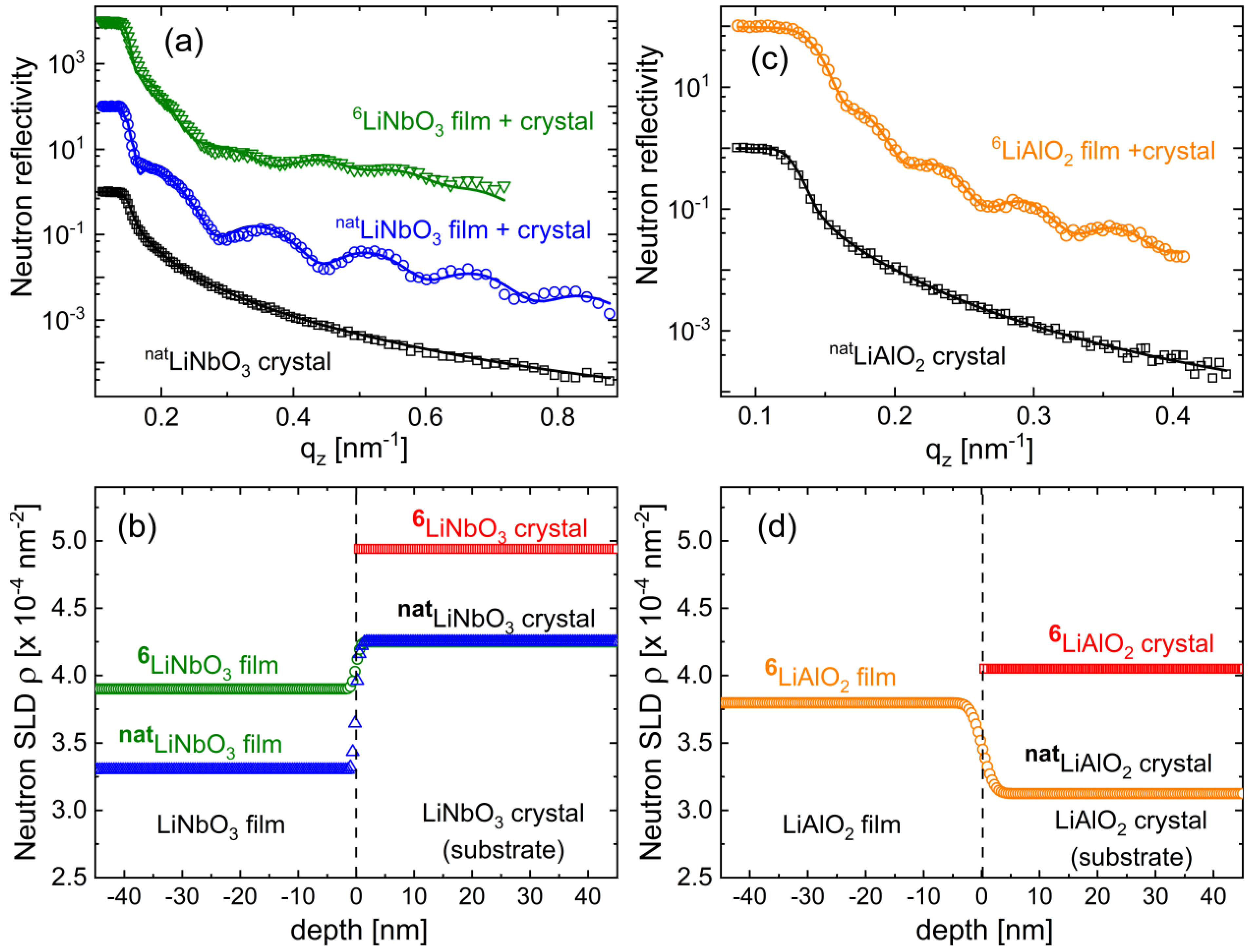
Figure 3a presents the measured NR pattern (black squares) and the corresponding simulation (continuous black line) of a bare LiNbO3 single crystal with natural Li isotope abundance, termed natLiNbO3. Except for the total reflection edge located at around 0.15 nm−1, the NR pattern shows no features. The measured NR pattern can be well fitted using a neutron scattering length density (SLD) of (4.25 ± 0.20) × 10−4 nm−2. The errors were obtained from a 10% increase in χ2 of the best fit with respect to the fitted parameter only. As mentioned, the SLD depends on two variables, the number density and the chemical composition. So, to calculate the mass density from the neutron SLD, one has to know the chemical composition. It can be considered that the chemical composition of the well-processed wafers corresponds to congruent LiNbO3. Under this assumption, a mass density of (4.60 ± 0.22) gcm−3 is obtained from the neutron SLD according to the neutron scattering density calculator [112]. That mass density is listed in Table 2 and corresponds to literature values of crystalline LiNbO3 [31].
The neutron pattern of the natLiNbO3 film deposited on the single crystal is presented in Figure 3a with blue circles. Oscillations (fringe patterns) are observed beyond the total reflection edge which proves that the neutron SLD (and consequently the mass density of the film) is different from that of the natLiNbO3 wafer. The pattern can be best fitted (continuous blue line in Figure 3a) considering that the sputtered natLiNbO3 film possesses a thickness of 37.5 nm and a neutron SLD of (3.30 ± 0.07) × 10−4 nm−2, which is well below that of the underlying natLiNbO3 wafer (Figure 3b). (Note that the fit is improved by considering an ultrathin (up to 10 nm) surface layer with a low neutron SLD between 0.4 × 10⁻⁴ nm−2 and 1.2 × 10⁻⁴ nm−2. This low SLD indicates either a (i) higher porosity at the surface than in the interior of the LiNbO3 and LiAlO2 films, or a (ii) surface contamination due to the air exposure. The SLD may provide some information on the surface contamination. Li2CO3 can be ruled out because the high scattering length of carbon and oxygen produces a high SLD of 3.5 × 10⁻⁴ nm−2. Lithium nitride (Li3N) and lithium hydroxide (LiOH) surface contamination may appear due to air exposure. Their low SLD of 1.2 × 10⁻⁴ nm−2 and 0.06 × 10⁻⁴ nm−2, respectively, may explain the lower SLD on the film surface. Experiments have shown that the mentioned ultrathin surface layer on amorphous LiNbO3 films is volatile and disappears already after a short (2 min) annealing at 200 °C. This indicates the presence of water traces on film surface. Roughness, e.g., due to porosity, enhances hydrophilicity (and hydrophobicity into super-hydrophobicity [113]). Thus, the porous ion-beam sputtered LiNbO3 films may well possess water traces on the surface. The SLD of water has a negative value of −0.06 × 10⁻⁴ nm−2. Thus, the presence of water-traces explains why (i) the surface of the LiNbO3 films possesses a reduced SLD, and (ii) why this ultrathin surface layer quickly disappears after a short low-temperature annealing treatment. This work focusses on the higher SLD in the interior of the LiNbO3 and LiAlO2 films).
Heating experiments to investigate the crystallization process of sputter-deposited amorphous LiNbO3 films found the as-deposited LiNbO3 films to possess stoichiometric composition [37]. Consequently, taking into account the film composition of LiNbO3, a mass density of (3.59 ± 0.08) gcm−3 is obtained from the neutron SLD of the film which is ≈22% lower than the mass density of the underlying natLiNbO3 wafer.
Note that the approximate congruent composition of the film was proven by film crystallization performed with annealing treatments at 700 °C. In order to check the Li concentration in the as-deposited (i.e., non-annealed) film, experiments with sputter-deposited LiNbO3 thin films enriched with 6Li (96% 6Li), termed 6LiNbO3 films for short, were performed (Figure 3a). NR found a neutron SLD of 3.9 × 10⁻⁴ nm−2 (Figure 3b) for the 6LiNbO3 film, which is larger than that of the natLiNbO3 film, as expected due to the higher neutron scattering length of the 6Li isotope than that of the 7Li isotope. Considering the congruent composition of LiNbO3 one obtains the mass density of (3.61 ± 0.14) gcm−3 for the 6LiNbO3 film, which agrees with that of the natLiNbO3 film (Table 2).
The elaboration to determine the Li concentration is performed as follows. LiNbO3 can be considered to be composed of Nb2O5 and Li2O entities (Nb2O5 + Li2O = 2LiNbO3). A higher or lower Li content can be expressed by the Li2O content in LiNbO3. It can be expressed by a variable x as LixNbO(2.5+x/2), where x = 1 corresponds to stoichiometric lithium-niobate. Hence, the neutron SLD for the natLiNbO3 film and 6LiNbO3 film can be expressed as
σ n a t L i N b O 3 f i l m S L D = N Li x NbO ( 2.5 + x / 2 ) x b 6 L i 0.074 + x b 7 L i 0.926 + b N b + 2.5 + x 2 b O V
σ 6 L i N b O 3 f i l m S L D = N Li x NbO ( 2.5 + x / 2 ) x b 6 L i 0.96 + x b 7 L i 0.04 + b N b + 2.5 + x 2 b O V
where NLixNbO(2.5+x/2) is the total number of LixNbO(2.5+x/2) units inside the film and V is the film volume. b6Li = 2 fm, b7Li = −2.22 fm, bNb = 7.054 fm, and bO = 5.803 fm is the coherent scattering length of 6Li, 7Li, Nb, and oxygen, respectively. The expression inside the square brackets of Equations (1) and (2) gives the scattering lengths multiplied by the abundances of their corresponding scatterers inside the LixNbO(2.5+x/2) chemical formula entity.
The total number of LixNbO(2.5+x/2) units inside the film can be expressed as
N Li x NbO ( 2.5 + x / 2 ) = m Li x NbO ( 2.5 + x / 2 ) M Li x NbO ( 2.5 + x / 2 ) = ρ Li x NbO ( 2.5 + x / 2 ) V M Li x NbO ( 2.5 + x / 2 )
where mLixNbO(2.5+x/2), MLixNbO(2.5+x/2), and ρLixNbO(2.5+x/2) is the film mass, the mass of the LixNbO(2.5+x/2) formula unit, and the film mass density, respectively. Using Equation (3), Equations (1) and (2) become
σ n a t L i N b O 3 f i l m S L D = ρ n a t L i N b O 3 f i l m x b 6 L i 0.074 + x b 7 L i 0.926 + b N b + 2.5 + x 2 b O M Li x NbO ( 2.5 + x / 2 )
σ 6 L i N b O 3 f i l m S L D = ρ 6 L i N b O 3 f i l m x b 6 L i 0.96 + x b 7 L i 0.04 + b N b + 2.5 + x 2 b O M Li x NbO ( 2.5 + x / 2 )
The equations can be easily solved, and one obtains Li1.1±0.05 NbO3.05±0.05 which is close to the stoichiometric composition of LiNbO3. Li1.1 NbO3.05 produces the measured neutron SLD of (3.30 ± 0.07) × 10−4 nm−2 if the mass density attains (3.61 ± 0.08) gcm−3. This value is identical within error limits with the film mass density of (3.59 ± 0.08) gcm−3 considering the film stoichiometry of LiNbO3. So, in the following, the sputter-deposited films are termed LiNbO3 with a mass density of (3.6 ± 0.08) gcm−3 (Table 2).

3.2.2. The Impact of Mass Density and Free Volume on Li Diffusivity

The Li diffusivity in amorphous LiAlO2 was found to be only five orders of magnitude higher than in crystalline LiAlO2 (Table 1). This can be well explained by a comparison of the NR results obtained on LiAlO2 (Figure 3c,d) with that on LiNbO3 (Figure 3a,b) with results listed in Table 2. The most direct comparison is performed by describing the NR investigation on the sputter-deposited 6LiALO2 film on natLiAlO2 crystalline substrate (Figure 3c). The neutron SLD obtained from NR measurements on the sputter-deposited 6LiAlO2 film is higher than that measured on the natLiAlO2 single crystal (Figure 3d), and not lower as in the case of LiNbO3 (Figure 3b). The measured neutron SLD of the natLiAlO2 single crystal (wafer) of (3.13 ± 0.17) × 10−4 nm−2 corresponds to a mass density of (2.61 ± 0.14) gcm−3, which is as expected for crystalline LiAlO2 (Table 2). The measured neutron SLD of the sputter-deposited amorphous 6LiAlO2 film ((3.80 ± 0.12) × 10−4 nm−2) corresponds to a mass density of (2.43 ± 0.08) gcm−3, which is ≈7% lower than that of crystalline LiAlO2 (Table 2). In the case of LiNbO3, the mass density of the sputter-deposited films was ≈22% lower than that of the crystalline phase (Table 2). This indicates that the open volume is higher in sputter-deposited LiNbO3 films than in sputter-deposited LiAlO2 films. Consequently, the difference in open volume explains why the Li diffusivity in sputter-deposited LiNbO3 films was found to be 2500 times larger than in sputter-deposited LiAlO2 films, although the Li diffusivity in LiNbO3 single crystals is 10,000 times smaller than that in LiAlO2 single crystals (see Table 1).
For the case of lithium gallate (LiGaO2), the Li diffusivity in sputter-deposited amorphous LiGaO2 films was found to be ten thousand times lower than in sputter-deposited amorphous LiNbO3 films (Table 1). Table 1 illustrates that ion-beam sputter-deposited amorphous LiNbO3 films are a good electrode material choice due to their high Li diffusivity and a high degree of porosity, both proper for LIB operation. The electrochemical performance is presented in the next section.

3.3. Electrochemical Investigations

We found that thin films, e.g., below 1 µm thickness, can be electrochemically cycled many times without additives. Nevertheless, the capacity of thin-film cathode materials such as that of magnetron sputter-deposited NMC films strongly decreases if produced with low Ar gas pressures during film deposition [114]. A gravimetric capacity of only 4 mAhg−1 is obtained for NMC films sputter-deposited at an Ar gas pressure of 0.5 Pa (50 × 10−4 mbar) [114]. This might be explained by a Li+-diffusion blocking process [114]. Low capacities of around 3 mAhg−1 for NMC films sputter-deposited under a low Ar gas pressure of 0.01 Pa (1 × 10⁻⁴ mbar) were also found in our laboratory, even for slow cycling with extremely low current densities of 0.03 µAcm−2 (C/20). These are very low capacities compared to those of other electrode materials. From this point of view, NMC electrodes with capacities below 5 mAhg−1 can be considered electrochemically inactive materials. Note that a suitable selection of sputter-deposition parameters and thermal-procedures raises the capacity of the NMC film to 120 mAhg−1 [115]. In contrast, an additional heat treatment is not necessary for amorphous LiNbO3 films, deposited at low Ar gas pressure of 0.01 Pa (1 × 10⁻⁴ mbar). These show capacities between 300 and 550 mAhg−1 even after hundreds of cycles as shown in Section 3.3.4.

3.3.1. Potential Resolved Li+ Uptake and Release during Voltammetry and Constant Current Cycling

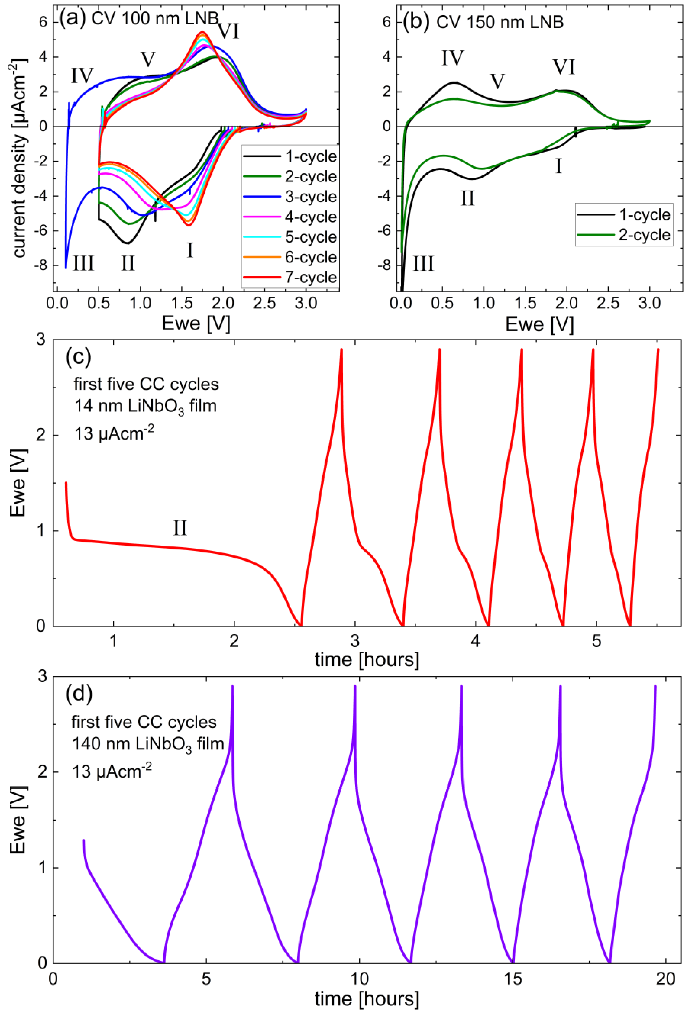
Figure 4 presents the potential and current behavior during the first lithiation and delithiation cycles of amorphous LiNbO3 thin film electrodes. Li+-uptake and Li+-release correspond in Figure 4a,b to negative and positive values, respectively.
Figure 4a presents the first seven CV cycles performed on the 100 nm thick LiNbO3 film electrode, measured between 0.5 V and 2.9 V. The limit of 0.5 V was chosen by considering the literature, which mentions that a lower cutoff voltage may result in a decreased cycle life at least in part due to SEI formation [55,64]. Ref. [55] notices that more lithium is inserted if the potential cutoff is moved to lower values. This statement is reproduced by the CV of the third cycle (blue curve) in Figure 4a. The first CV cycle (black curve in Figure 4a) shows a small predominant Li+-uptake marked with the Roman numeral I, which is actually a shoulder centered at a potential of ≈1.7 V. A stronger one is marked with II and is centered at ≈0.8 V. The Li+-release part shows two broad peaks marked with V and VI. The additional Li+-uptake and Li+-release appearing in the third circle (blue CV curve) are marked with III and IV, respectively. During cycling, peak II and V diminishes, and peak I and VI increases (Figure 4a). Thus, the Li+-uptake I, II, and III may be correlated with the Li+-releases VI, V, and IV, respectively. Note that the Li+-release increases at the upper cutoff potential of 3.0 V, which suggests the existence of a predominant Li+-release at potentials higher than 3 V, similar to NMC cathode materials.
The predominant Li+-uptake and Li+-release peaks presented in Figure 4a are reported also for the cycling of Nb-based oxides [87] such as LiNbO2 [88], porous crystalline LiNbO3 [53], KxLiyNbO3 [77], and niobium-oxide polymorphs [16,55,58,63,75,87,116,117,118,119]. They were observed also for metal oxides such as iron oxide [120,121], cobalt oxide [121,122], titanium oxide [123], molybdenum oxide [124,125], and copper oxide [122]. The literature attributes the peak I to (i) Li intercalation corresponding to the oxidation state transitions Nb5+ to Nb4+ (Nb5+ is present in niobium pentoxide Nb2O5, and Nb4+ in niobium dioxide NbO2) [16,58,87], (ii) Li insertion into the metal oxide to form a solid-solution like compound [120], or (iii) a conversion reaction. The full conversion reaction 5(Li+ + e) + LiNbO3 = 3Li2O + Nb may consume a lot of Li stock. Note that this five-electron reaction should be the total reduction reaction, which cannot be assigned fully to peak I due to the existence of subsequent peaks, i.e., peak I should only be the first step of a possible total reduction reaction. More probably, peak I may correspond to a partial reduction.
The Li+ uptake II was allocated to the conversion reaction of the metal oxide [119] and may be tentatively attributed to the Nb4+/Nb3+ redox couple [16]. Furthermore, peak II is observed in the first CV cycle from electrodes consisting of NbO2 grains embedded inside a carbon matrix [118], and for mesoporous Nb2O5 particles/grains embedded in carbon additives [116]. They were attributed to the lithiation of the resin-derived hard carbon [118] and the formation of a solid-state interphase layer [116]. The predominant Li+ uptake III is attributed to SEI film formation by Refs. [120,122]. TEM experiments on the lithiation and delithiation investigation of CoO [122] found peak III (Figure 4a) to correspond to a reversible growth of a polymeric gel-like film resulting from electrolyte degradation. Peak III is attributed to the lithiation of carbon in Ref. [118]. Note that both peaks, i.e., II and III, lie below 1 V vs. Li reference electrode, where excessive SEI layer formation may appear [64].
Peak I and VI shift with cycling (Figure 4a). The potential of Li+-uptake I is closer to its associated Li+-release peak VI, i.e., the potential hysteresis reduces down to 0.15 V at the seventh CV cycle (red curve in Figure 4a), which is beneficial for LIB operation. This points to an easy Li+ extraction and insertion, similar to that in graphite, as discussed in Ref. [27]. In comparison, for the case of 3D-porous crystalline LiNbO3 [53], the potential hysteresis amounts to 0.3 V. This points to higher Li+ and electron conductivity in porous amorphous LiNbO3 than in porous crystalline LiNbO3. A very low potential hysteresis can be found also for niobium-oxide polymorphs [55,63,75,116,117,118,119], which is explained via NMR to arise from a very low activation energy for Li diffusion of below 0.1 eV. The lithiation and delithiation mechanism is thought to be an intercalation and de-intercalation process of Li into the niobium-oxide host [55,117]. This finding is in contradiction to the literature data on the reactivity of metal-oxide compounds toward Li, which explains the mechanism by a conversion reaction [122]. TEM investigations [122] indicate a reversible conversion of Co-oxide into Co-metal nanograins embedded into the LiO2 matrix. In that case, the delithiation process should be a Li extraction from Li2O, which is effortful. Consequently, a reversible conversion process should rather possess a large potential hysteresis between Li+-insertion and Li+-release. The potential hysteresis amounts to ~0.5 V for the case of CoO [122] and TiO2 [123]. This casts doubts on the hypothesis that the couple (I,VI) in Figure 4a,b may originate from a conversion reaction. SEI layer formation as the reason for peak I development may be excluded according to its potential position. The high potential of peak I (1.6 V) in Figure 4a is similar to that of Li4Ti5O12 and matches well with the lowest unoccupied molecular orbital of the carbonate electrolytes, stopping SEI films and lithium dendrites growth [61]. In the following sections, information about the peaks I to VI of Figure 4a is sought by comparing results obtained from films of different thicknesses.
Figure 4b presents the first two CV cycles performed on the 150 nm LiNbO3 film. The Li+ uptakes and releases are similar but broader than those of the 100 nm films. The other film thicknesses, i.e., the 14 nm and 140 nm thick amorphous LiNbO3 films were only cycled with CC. The potential profiles of the first five cycles in the cycling range of 0.001 V to 2.9 V are presented in Figure 4c,d. The thinner film shows a long-time plateau located around 0.8 V in the first cycle which is marked with II in Figure 4c. Potential plateaus in potential profiles produce peaks in dQ/dV plots [27].
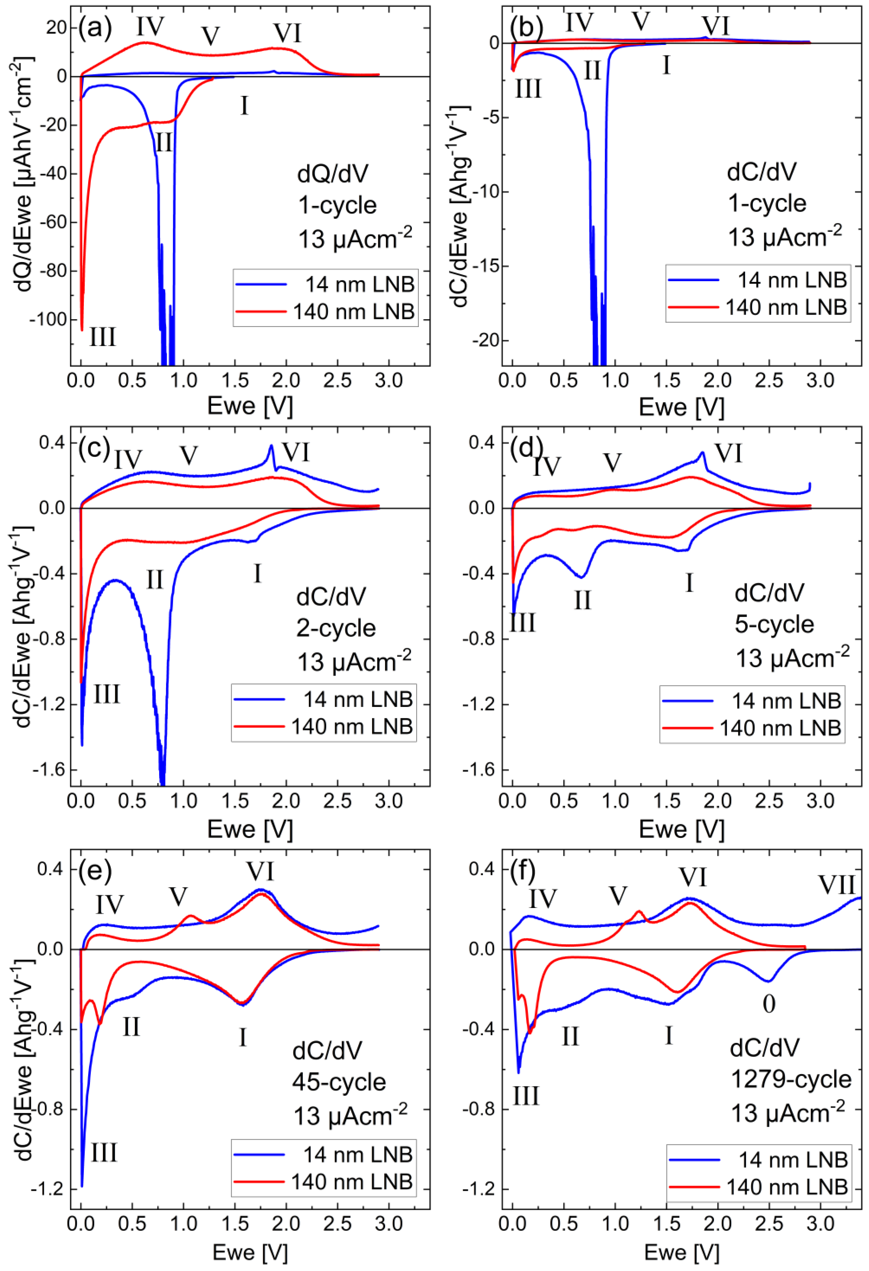
A direct comparison of differential Li+-uptake and -release charge at each potential (dQ/dV plot) of 14 nm and 140 nm LiNbO3 films is presented in Figure 5 for the first (Figure 5a,b), second (Figure 5c), fifth (Figure 5d), 45th (Figure 5e), and 1279th (Figure 5f) CC cycle. The current density corresponds to a rate of about 2C and 1C at the 1279th (Figure 5f) cycle for the thinner and thicker film, respectively. In the first cycle (Figure 5a), the predominant Li+ uptake II is small for the thicker film, but it is very strong for the thinner film, which reflects the long-time potential plateau II in Figure 4c.
Figure 5b shows the dQ/dV plots corresponding to Figure 5a divided by the mass of the LiNbO3 film, and in that manner, it shows the potential distribution of the gravimetric capacity (dC/dV). The comparison between the dQ/dV and dC/dV curves (Figure 5a,b) indicates that the Li+-uptake II is more predominant in the thinner LiNbO3 film, a fact that is discussed in more detail later. At first sight, one may attribute this to SEI layer formation. One may assume that the SEI layer thickness is similar for both LiNbO3 films. Note that because thicker films need longer time intervals for lithiation, thicker SEI layers may grow. So, the SEI layer would be thicker, but at least not thinner, on the thicker LiNbO3 film. Consequently, the Li+-uptake II of the thicker film has to be at least not lower, which is not the case in Figure 5a, where the opposite was observed. Thus, there has to be another mechanism than SEI formation for the Li+-uptake II.
As mentioned, peak II may be attributed also to a conversion reaction. Full conversion means that the metal oxide is transformed into a Li2O matrix into which Nb-metal clusters are embedded. The charge density per 1 cm2 surface unit (ChD) can be calculated according to the conversion reaction 5(Li+ + e) + LiNbO3 = 3Li2O + Nb,
C h D = C h I · N L N B A L N B f i l m = 5 e · m L N B f i l m M L N B · A L N B f i l m = 5 e · d L N B f i l m · ρ L N B f i l m M L N B = 5 e · d L N B f i l m · 3.6   g c m 3 147.8   g · N A 1
where ChI is the Li+ charge inserted into one LiNbO3 formula unit, e.g., ChI = 5e according to the full conversion 5(Li+ + e) + LiNbO3 = 3Li2O + Nb. NLNB represents the total number of LiNbO3 formulas involved in the lithiation process. A LNB film and m LNB film are the area and mass, respectively. MLNB is the molar mass of LiNbO3. d LNB film and ρ LNB film are the thickness and mass density, respectively. NA is the Avogadro constant. The Li+ uptake according to the full conversion reaction 5(Li+ + e) +LiNbO3 = 3Li2O + Nb should then amount to 4.6 µAhcm−2 and 46 µAhcm−2 for the 14 nm and 140 nm LiNbO3 film electrode, respectively.
The charge density for the measured Li+-uptake II presented in Figure 5a was found to be between 1 V and 0.5 V, and amounts to 21 µAhcm−2 and 8 µAhcm−2 for the 14 nm and 140 thin LiNbO3 film, respectively. Hence, the following consequences for the lithiation mechanism of the thicker and thinner LiNbO3 films result. The Li+-uptake II peak of the thicker LiNbO3 film may correspond to the conversion reaction of (Li+ + e) + LiNbO3 = Li2O + NbO2 which necessities a Li+ amount of 9 µAhcm−2 as theoretically calculated for that conversion reaction. This value is in close agreement with that obtained from Figure 5a of 8 µAhcm−2. Peak II of the thinner film cannot be solely explained with a conversion reaction because the charge consumed by peak II of 21 µAhcm−2 is much higher than that of a full conversion of the 14 nm thick layer (4.6 µAhcm−2). As discussed above, peak II of the thinner film also cannot be explained by SEI layer formation. The potential of 0.75 V with respect to the Li-metal reference excludes also Li-plating. So, peak II represents a peculiar huge Li+ uptake inside thin LiNbO3 films. A space charge layer inside the whole 14 nm thick layer [126,127,128] due to a Schottky contact of the LiNbO3 film to the copper current collector may be an explanation [128]. Note that a space charge layer has to be present also on the LiNbO3/Cu interface of the thicker film. The Li+ uptake inside the space charge layer in the case of the thinner LiNbO3 film has to be larger because the peak intensity of peak II is higher for the 14 nm than for the 140 nm LiNbO3 film. Quantum size effects (QSE) [129] in the thinner film may explain the different space charge layer in the thinner film.
During cycling (Figure 5), the capacity of Li+-uptakes II and III decreases, and that of Li+-uptake I and Li+ release peak VI enhances. The reduction of the Li+-uptake III is smaller than that of peak II, which possesses, as expected, the strongest reduction in the case of the thinnest LiNbO3 film. Note the similarity of the second cycle dC/dV curve of the 140 nm film (Figure 5c) with the second cycle CV curve of the 150 nm film (Figure 4b) which proves the similarity of dQ/dV curves (and obviously, dC/dV curves) with CV curves.
The upper cutoff voltage for the 1279th CC cycle of the thinner LiNbO3 film (Figure 5f) was set to 3.8 V and one observes an additional Li+ uptake marked with 0 located around 2.5 V, together with the indication of a corresponding Li+-release peak marked with VII, located above 3.75 V. This high voltage Li+-release peak is similar to that of high-voltage cathode materials such as LiCoO2 (e.g., Figures 4 and 5 in Ref. [10]) and NMC. Hence, the couple (0,VII) may indicate that nano-sized LiNbO3 such as 14 nm thick layers may be used also as a high-voltage (cathode) electrochemically active material.
The electron conductivity in amorphous ultrathin LiNbO3 films is expected to be too high to use them as a solid electrolyte. Consequently, according to the potential-resolved data for Li+ uptake and Li+ release (Figure 4 and Figure 5), amorphous ultrathin LiNbO3 films may be used as material for LIB negative cathodes, and presumably also for positive electrodes, if peaks at 3 V or higher (e.g., peak VII in Figure 5f) can be identified. At higher cycles (Figure 5e,f), the dC/dV curves of the thinner LiNbO3 film possess a more structureless shape, similar to supercapacitors [58,59,60,130,131], confirming the high Li mobility in amorphous LiNbO3. The cycling in pseudo-capacitive materials appears in the bulk of the electrode [131], at confined regions, which are present in porous materials. The experiments performed to investigate the pseudo-capacitive behavior of LiNbO3 films are presented in Figure 6.

3.3.2. Pseudo-Capacitive Determination

The examination of pseudo-capacitive behavior is performed on peaks (I,V) because they are located above 1 V vs. Li-metal reference. That means they are inside the stability window of the state-of-the-art carbon-based electrolytes (see Figure 1 in Ref. [64]). Figure 6a presents the CV of the 8th to 14th cycle performed with sequentially increased sweep rate. The time-interval of the CV cycle is controlled by the sweep rate (ν) given in microvolts per second. The higher the sweep rate, the higher the C-rate, and consequently, the higher the current response. The latter varies also depending on the Li+ insertion and release process [59,60,62,123]. Pseudocapacitive behavior can be examined by plotting the sweep rate (ν) in dependence of the current (i), i.e., i(ν) from CV. This can be done at all investigated potentials.
The response current is often a combination of two separate mechanisms, namely, (i) a diffusion-controlled insertion with a diffusion current dependence of idiffusion = 0.5, and (ii) a surface capacitive effect (including double-layer capacitance and intercalation pseudocapacitive behavior) whose current response is a linear function of the sweep rate icapacitive = . Consequently, the current response is given by i = 0.5 + , where the constants a and b deliver the fractions of diffusion-controlled and pseudo-capacitive character, respectively. The pseudo-capacitive fraction for the amorphous 100 nm LiNbO3 film electrode, cycled between 0.5 and 3 V is presented in Figure 6b. It can be observed that the Li+ insertion and release process between 1.2 V and 2 V (region of peaks (I,VI)) is exclusively of a pseudocapacitive nature (Figure 6b–e). The Li+ insertion and release process in the potential range between 0.5 V and 1 V (region of peaks (II,V)) corresponds preponderantly to a diffusion-controlled mechanism (Figure 6b,f). Hence, Li+-uptake I possesses a capacitive character (Figure 4), probably due to the lithiation of the mesopore surface of the amorphous LiNbO3 films. The Li+ uptake II has a more bulk diffusion-controlled character (Figure 4), probably due to the lithiation of the interior of the mesopore walls of the amorphous LiNbO3 films.

3.3.3. Electrochemical Impedance Spectroscopy Investigations

Figure 7a,b presents the EIS measurements, and the corresponding fits with the equivalent circuit presented in Figure 7b, for the 100 nm LiNbO3 film (i) before lithiation, (ii) at full lithiated, and (iii) at delithiated states. The Li+ diffusion coefficients gained from the EIS examination are presented in Figure 7c. The EIS spectra from the delithiated states are similar to each other, irrespective of the cycle number, and they are also similar to that before Li insertion (Figure 7b). Marked differences in EIS data appeared only between lithiated and delithiated states. The Randles circuit R2/Q1 corresponds to the region of low impedance (the depressed half circles) in Figure 7a,b. and are strongly reduced in the lithiated states. This can be attributed to an improved electron conductivity of the film surface in the lithiated state.
The equivalent circuit element M1 represents a mass transport impedance element for Li confined in the LiNbO3 film [132,133], from which one can determine the Li diffusivities [133] plotted in Figure 7c. The Li diffusivity in the virgin state, i.e., before first lithiation, amounts to ≈1 × 10⁻¹⁵ m2s−1 which is three orders of magnitude higher than that measured by SIMS in amorphous LiNbO3 films (which amounts to ≈1 × 10⁻¹⁸ m2s−1, see Table 1). Note that it is considered that electrochemically methods measure fast Li+ diffusion paths (e.g., due to chemical diffusivities), whereas the SIMS data catches also the slow Li+ diffusion paths. From that point of view, direct comparisons between Li diffusivities obtained by electrochemical measurement methods and those by standard diffusion measurement techniques such as SIMS are not always appropriate. However, discrepancies will be discussed later during the estimation of Li diffusivities from rate capability experiments

3.3.4. Long-Term Cycling and Rate Capability Experiments

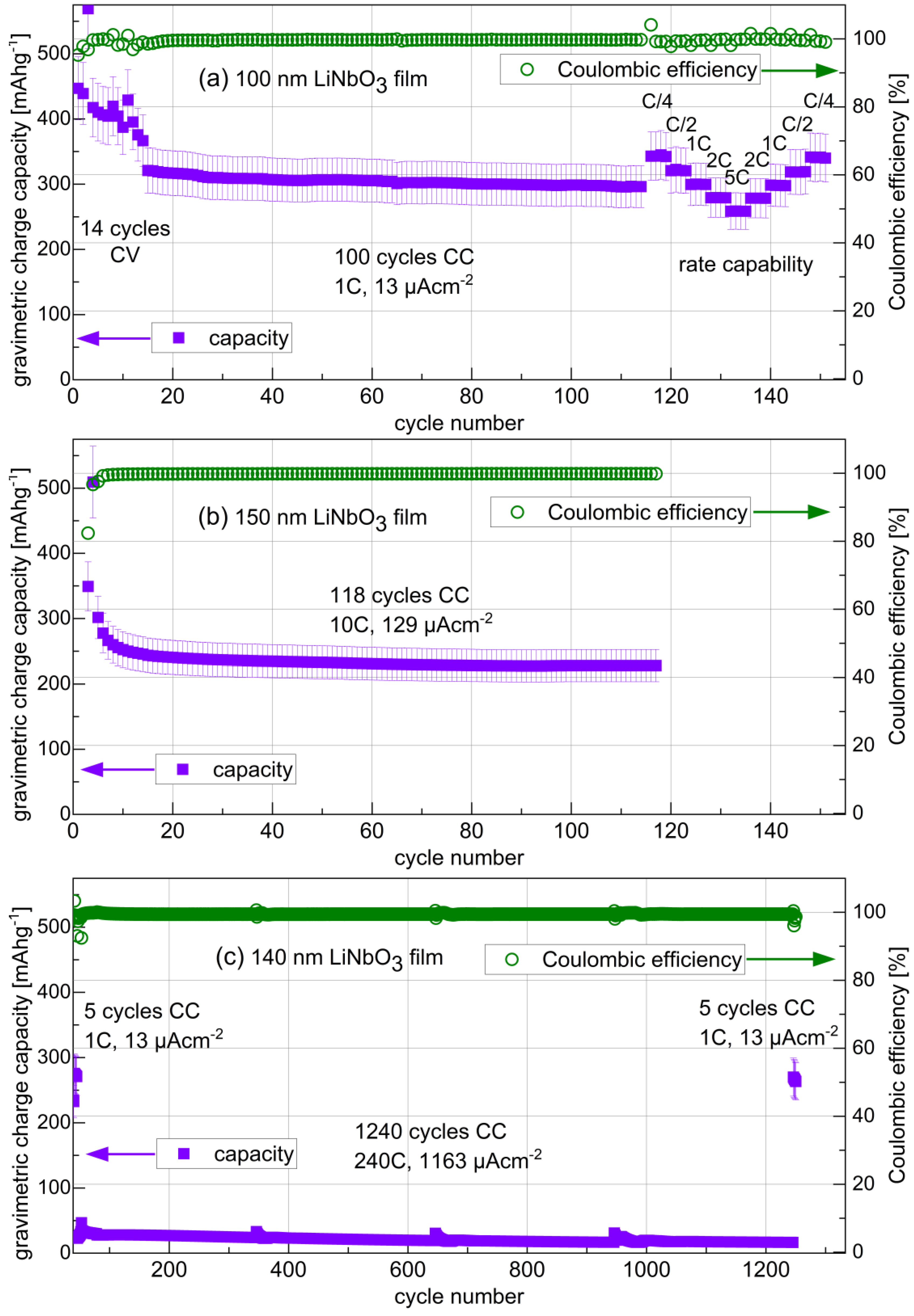
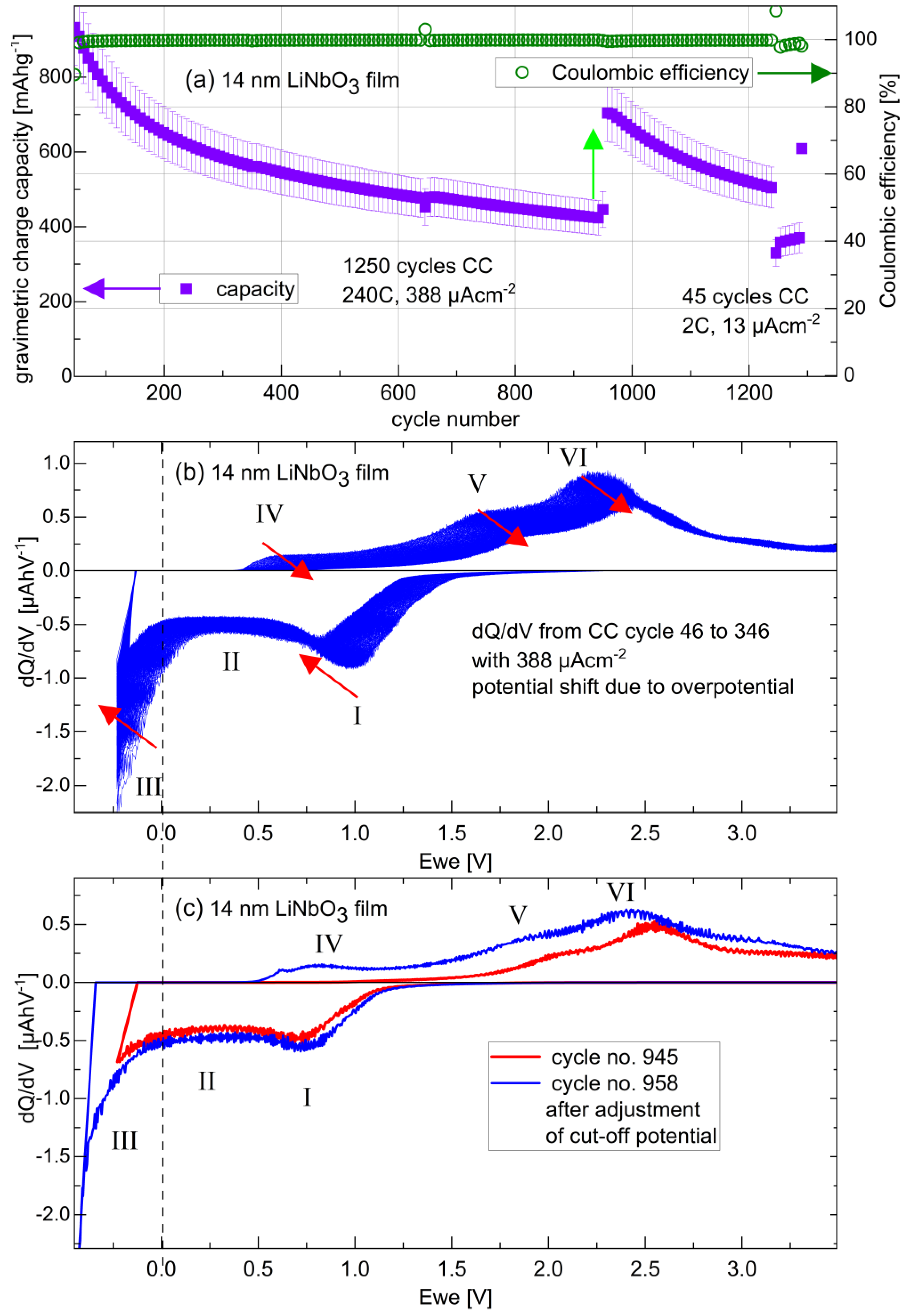
Figure 8a presents the gravimetric capacity and Coulombic efficiency obtained for the 100 nm LiNbO3 film electrode. All cycles were performed between 0.5 V and 2.9 V, except for the third cycle, which was cycled down to 0.1 V (Figure 4a) increasing the capacity at the third cycle. During CV cycling with a constant sweep rate, i.e., up to cycle number 7, the capacity decreased to a value of about 420 mAhg−1. After the 7th cycle, the sweep rate was increased, and the capacity again decreases due to higher rates at higher sweep rates. After the 14th cycle, the film electrode was cycled with CC at a rate of approx. 1C for further 100 cycles. The capacity remains constant and, correspondingly, with almost 100% Coulombic efficiency, which evidences good cycling stability of the ion-beam sputter-deposited LiNbO3 film. Afterward, a rate capability experiment (between cycle numbers 117 and 151) was performed (Figure 8a). Consecutive blocks of four CC cycles with stepwise ascending current from 1.8 to 28.3 µAcm−2 were performed. Then, the same procedure was reversed, i.e., with descending currents. The applied currents produced the rates mentioned in Figure 8a. Higher rates slightly decrease the capacity, but cycling back to lower currents (cycles 125 to 151) restores the capacity, indicating good cycle stability.
The other LiNbO3 films were cycled at higher rates to investigate the ability of LiNbO3 for fast cycling (Figure 8b,c and Figure 9). Figure 8b presents the capacity and Coulombic efficiency of 118 CC cycles on the 150 nm LiNbO3 film with a rate of 10C, performed between 3 V and just before Li plating onset (i.e., up to −0.085 V, see Figure 9b). The Li-plating appeared at negative potentials with respect to the Li-metal reference electrode due to overpotentials (see, e.g., Figure 2 in Ref. [27] for further explanation). Overpotentials, and in that way, the shift of Li-plating to negative potentials, enhances at a high rate due to higher Li+ current densities [27]. The capacity decreases until the tenth cycle (Figure 8b), stabilizing afterward to ≈230 mAhg−1 for more than additional 100 cycles, evidencing good stability also at fast cycling.
Figure 8c presents the long-term cycling of the 140 nm LiNbO3 film electrode for CC cycling up to Li-plating onset at the high rate of 240C, which means an (apparent) full lithiation in only 15 s. The capacity decreases to less than 40 mAhg−1, but it increases again to the preceding capacity of 250 mAhg−1 if the LiNbO3 film is subsequently cycled with a low rate of 1C (Figure 8c). This indicates that the capacity decrease during fast cycling is not due to film destruction, but due to kinetic limitations (Li diffusivity) at fast cycling. Li diffusion in the LiNbO3 film affects the lithiation process. For high current density and low Li diffusivity, Li plating appears on the electrode surface before full lithiation of the whole LiNbO3 film is reached. Once Li plating appears, the CC lithiation process is stopped, and the capacity does not reach its full value. So, because the decrease of the capacity (Figure 8 and Figure 9) is connected to Li diffusion by the time intervals for Li to spread into the whole film, the Li diffusivity can be estimated from the rate capability experiments as follows.
The rate is given by the lithiation time interval needed to reach the lower cutoff potential, i.e., by (1h)/t. It would be of desire to recognize the highest possible rate value at which the whole film still reaches full lithiation. The corresponding characteristic time, further denoted with tC, may be used to estimate the Li diffusivity (D) according to D = d2/(2tC), where d is the film thickness, e.g., d ≈ 100 nm in the case of Figure 8a. By comparing the capacities in Figure 8b,c obtained at 10C and 240C, respectively, one can assume that the Li-diffusion process cannot fully lithiate the film at 240C. So, from the rate of 240C, the time needed for Li to widespread into the whole films is tC > (1h)/240 = 15 s. Consequently, D < 1 × 10⁻¹⁵ m2s−1 is obtained from the rate of 240C, which is below the diffusivities obtained from EIS experiments (Figure 7c). The rate capability experiments given in Figure 8a will be considered in order to gain more precise diffusivity data. The rate capability experiment in Figure 8a shows a symmetrical recovery in the capacities when cycled back to the lower current densities. For example, the capacities at 1C in the current ascending (cycles number 121 to 124) and descending (cycles 145 to 149) branches are equal to each other, and even equal to that before the rate capability experiment (Figure 8a). This means that the LiNbO3 film is stable during the rate capability experiment and the film material does not change from one to the next cycle during the rate capability experiment, and the capacity decrease is due to Li kinetics. There, the capacity decreases already going from a rate of C/4 to that of C/2. This means that the rate from which the Li diffusion process starts to be unable to transport enough Li into the film to enable a full lithiation of the whole 100 nm thick film, corresponds to C/2. Thus, from Figure 8a, the critical C-rate before Li plated on the electrode surface is C/2 for the 100 nm thick LiNbO3 film. Obviously, this critical C-rate considerably enhances in the case of thinner LiNbO3 films. Further experiments on the 15 nm thick LiNbO3 film revealed a critical C-rate of 157C, which points to pronounced interface (electrolyte/film and current-collector/film interface) effects and quantum size effects (QSE) [125] in the lithiation process of the thinnest LiNbO3 film. However, these interface and QSE effects should be less pronounced in the lithiation process of a higher amount of LiNbO3 material, i.e., for the thicker LiNbO3 film. So, the sought-after characteristic Li diffusion time for the Li transport into the whole 100 nm LiNbO3 film is approximated with that of C/2, i.e., tC ≈ 0.5 h. In that case, the Li diffusivity amounts to D ≈ 3 × 10⁻¹⁸ m2s−1. This is three orders of magnitude below that obtained from EIS experiments (Figure 7c) but of the same order of magnitude as that measured with the state-of-the-art diffusion measurement technique SIMS of D ≈ 1 × 10⁻¹⁸ m2s−1 (Table 1). Hence, adequately applied diffusion measurement techniques, in this case, SIMS depth profiling, describe the cycling process of LIB electrodes. Note that it is not actually clear whether the Li diffusion in the LiNbO3 film or Li diffusion in the electrolyte dominates the kinetic bottleneck. The 1M LiClO4 salt in the PC solvent may also cause the kinetic issue. In that context, rate capability experiments with other electrolytes may shed light on this problem. Slow Li diffusion in the electrolyte may also cause the overpotential increasing issue, which is presented in discussing Figure 9.
Figure 9 presents the results of prolonged CC cycling with the high current density of 388 µAcm−2 of the 14 nm LiNbO3 film, beyond initial cycling with 13 µAcm−2. The high current density produced a rate of 240C, i.e., the lithiation is completed in 15 s. The capacity decays from ≈800 mAhg−1 to ≈400 mAhg−1 after 950 cycles. Even 400 mAhg−1 is a very high capacity, much higher than that for thicker LiNbO3 films, which is less than 40 mAhg−1 (Figure 8c). Such a film thickness effect on capacity was observed also for the cycling of LiNbO3 crystallites [21,47,51,53]. After 950 cycles (Figure 9a), the film electrode stayed in open circuit voltage (OCV) overnight (≈12 h) with a subsequent readjustment of the low potential cutoff voltage to ensure lithiation up to Li-plating onset. This affected the capacity at further cycling, as can be seen from the capacity gap at cycle number 955 marked with a light green vertical arrow in Figure 9a. The capacity first achieves a higher value of ≈640 mAhg−1 and then decreases to 455 mAhg−1 during the next 300 cycles. Cycling with a low current of 13 µAcm−2 restores the capacity again to 550 mAhg−1 at cycle number 1298. dQ/dV curves may give some answers to this capacity behavior.
The initial cutoff potential for the lithiation process presented in Figure 9 was set to −0.22 V vs. Li reference electrode due to the overpotential. Prolonged cycling increases the overpotential, which shifts the Li+-uptake to more negative potentials. Consequently, the potential of Li+-uptake III is continuously pushed below the cutoff potential, which continuously decreases the Li+-uptake III (Figure 9b,c). The potential shift is well observed on the corresponding Li+-releases IV and V. Both Li+-release peaks are shifted due to the growing overpotential, and the Li+-release peak IV continuously decreases (curved red arrow) due to the continuous decay of the Li+-uptake III. Figure 9c presents the dQ/dV curves of a cycle before (red curve) and after (blue curve) overnight open circuit potential, with subsequent readjustment of the cutoff potential for lithiation up to Li plating (i.e., before and after the vertical arrow in Figure 9a). The readjustment of the cutoff potential moves the cutoff potential to stronger negative values (Figure 9c) from −0.22 V to −0.43 V, indicating an overpotential that increased by 0.21 V during cycling. This overpotential increase is the reason for the capacity decrease during the long-term cycling presented in Figure 9a and not a degradation of amorphous LiNbO3.
In order to rank the high reversible capacity of the 14 nm LiNbO3 film electrode, Table 3 lists the reversible capacities of the 14 nm LiNbO3 film electrode in comparison to those obtained in our laboratory for ion-beam sputter-deposited amorphous silicon, carbon, and germanium thin-film electrodes, after prolonged cycling at high current densities. The theoretical capacity is in practice often not achieved likely due to kinetic overpotentials.
The theoretical capacity of Nb-based oxides is up to 402 mAhg−1 [62,63,87], which is close to that of graphite (372 mAhg−1) [27] but much lower than that experimentally achievable by silicon (3579 mAhg−1) [29,30,134,135,136,137,138] and germanium (1385 mAhg−1) [139]. Nevertheless, at high cycle numbers and high current densities (Table 3), the gravimetric and volumetric capacity of amorphous LiNbO3 thin films is higher than that achievable by amorphous silicon, carbon, and germanium thin-film electrodes cycled similarly, i.e., at high cycle numbers, at high current densities, and between similar potentials. The volumetric capacities (CV) were obtained by multiplying the gravimetric capacities (Cg) with the film mass density (CV = Cg·ρfilm). The film densities were determined with NR and are listed in Table 3. A remark on reporting gravimetric and volumetric capacities is given in the next section. Notice the restriction that, unfortunately, the results for the silicon, carbon, and germanium thin-film electrodes were obtained at higher current density. The higher reversible capacity of LiNbO3 films at high cycles numbers and high rates compared to those of amorphous silicon, carbon, and germanium films (Table 3), may stem from the porosity of the LiNbO3 films (succinctly: “the holes matter”) and, perhaps, also from the potential position of the Li+ uptakes and releases O, I, VI, VII within the stability window of carbon-based electrolytes [64].

3.4. Remarks, Open Questions, and Outlook

The reason for the continuous increase in the overpotential during cycling remains unknown. On the one hand, it may be related to SEI layer formation, which should be properly investigated with EIS and NR measurements. Operando NR examination is suitable to crosscheck the interpretation of the EIS data. Operando NR allows for investigations without washing procedures and exposure to air, argon gas, or high vacuum. On the other hand, the overpotential increase may be connected to changes in the ferroelectric domains during the cycling of the LiNbO3 films. It is interesting that ferroelectricity was observed in sputter-deposited amorphous LiNbO3 films [99]. It remains a challenge to investigate in situ and operando the ferroelectricity during electrode cycling. Overpotentials may be significantly reduced by dopants or by intermixing agents such as carbon black.
The reason for the huge irreversible Li+ uptake during the initial cycling of the 14 nm LiNbO3 film electrode remains also unresolved. One reason may be an additional Li+ storage at interfaces in space charge layers [126,127,128,140] changed by QSE [129]. Operando EIS together with operando NR experiments flanked by SIMS depth profiles is expected to elucidate the film depth position where the huge irreversible Li+ uptake takes place. The results obtained from SIMS depth profiling will not be overlapping but complementary to those obtained from NR depth profiling. SIMS is more Li-sensitive than NR for lower Li contents, and vice versa for high Li content. The Li+ SIMS signal is of high intensity. On the one hand, the measured Li isotope SIMS signals are easily obtained to be even higher than 1 million counts per second. This enables SIMS to detect Li traces. This is suitable to discern Li contents between 1% and 10%, which is a challenge for NR. On the other hand, the experience in our laboratory with SIMS is that it is more difficult to discern between Li contents higher than 50%. These can be more suitably discerned by NR (via the thickness variation). NR is able to determine the thickness of the LiNbO3 films during cycling with sub-nanometer resolution.
The potential-resolved data (i.e., CV, dQ/dV, dC/dV) shown in this work display four predominant Li+ uptakes (marked with 0, I, II, and III in Figure 4 and Figure 5) and four predominant Li+ releases (marked with VI, V, VI, and VII in Figure 4 and Figure 5). In fact, there nothing is known about the lithiation and delithiation mechanisms. It is not known how the Li distribution evolves inside the film electrode during cycling. It is of interest to elucidate the mechanisms. Note that it is unknown how the Li-insertion (and Li+-extraction) front proceeds into the amorphous LiNbO3 films, e.g., whether there is a diffusion-like, homogenous-like, or phase-front-like distribution of Li inside the film electrode during cycling. Such investigations can be performed, as abovementioned, by measuring Li depth profiles with SIMS [141] and NR [141] at different states of charge, at different cycles, and for different film thicknesses. Furthermore, 6Li/7Li isotope exchange experiments with SIMS in depth-profiling and (laterally) line-scan modes, may determine Li diffusivities on the nm up to the mm scale in the electrode, respectively. The 6Li/7Li isotope exchange experiments can be also performed at different SOC, at different cycles, and for different film thicknesses. Let us again emphasize that NR is able to investigate operando the thicknesses variation of films and even that of buried layers during cycling [141].
Throughout the literature, LIB electrode capacity values are often reported in units of gravimetric capacities (e.g., mAhg−1). For reports on thin-film electrodes, the film mass density and even the film thicknesses are often not mentioned and are probably unknown. Consequently, gravimetric and volumetric capacities are not reported, and the capacity values are reported in charge per surface area unit, e.g., in units of mAhcm−2. The film mass density and the film volume were determined in this work by neutron reflectometry. Consequently, in this work, gravimetric and volumetric capacities are reported. The capacities in this work are given in gravimetric capacities, but, due to known film mass density (and volume by determination of film thickness and of the film surface area which was involved in cycling), they can also be expressed as volumetric capacities. In a recent review [26], it is explained that the expression of capacity values in volumetric capacity is even more important in practical cells than that given in gravimetric capacity. Volumetric capacities are listed in the last column of Table 3.
Amorphous niobium oxides such as niobium pentoxide are expected to behave similarly to amorphous LiNbO3. This claim can also be examined by electrochemical, NR, and SIMS investigations.
As reviewed in this work, literature reports state that LiNbO3 additives on the surface of cathodic active materials improve LIB operation. This is called surface engineering [104]. The results of the present work revealed the amorphous LiNbO3 films to show good cycling performance with capacities as high as 600 mAhg−1 also after hundreds of fast cycling with rates of 240 C. According to these results, LiNbO3 has the perspective to enable a so-called bulk engineering for LIB improvement. This means that LiNbO3 additives, preferably in the form of porous and amorphous LiNbO3, inside the bulk of electrochemically active materials, may enable fast cycling with high reversible capacity also with materials where until now this is not possible.
Proposals for future research directions and opportunities in fast charging may concern multilayers with a high repetition of LiNbO3/M bilayers with M = active anode materials (C, Si, Ge, or Al) or active cathode materials (NMC). They may enable fast cycling with high capacity also in the case of a relatively high amount of Si, Ge, and NMC material. Last but not least, the cycling of Li-Nb-O material at high potentials at least up to 5 V vs. Li metal reference electrode, should be performed in order to examine the suitability of Li-Nb-O-based materials as high-voltage cathode materials. This proposed further future research direction is not limited to Li+ batteries but should also be extended to examine the cycling performance of LiNbO3/M multilayers toward Na+, K+, and Mn2+.
The examination of the cycling performance of proton-exchanged LiNbO3 (as an example for doped LiNbO3 material) toward Li+, Na+, K+, and Mn2+ batteries, is also a future research direction, in order to even further enhance kinetics during cycling. The proton-exchange process can be carried out in a mixture of benzoic acid and lithium benzoate. During proton exchange, lithium is replaced by hydrogen and Li1−xHxNbO3 is formed, with x up to 0.85 [142]. In the case of LiNbO3 single crystals, proton exchange resulted in micrometric-thick surface layers where Li is substituted by hydrogen. The Li diffusivity was measured to increase by many orders of magnitude when the H content is increased [142]. Thus, cycling of partially proton-exchanged amorphous LiNbO3 may further boost Li kinetics. Recently [143] it was shown that the easy H-bonding switch in H2V3O8 high-capacity LIB cathode material upon Li+ insertion not only allows better accommodation of inserted Li+ but also enhances Li-ion mobility. The mobility of Li+ is favored by electrostatic repulsion between Li+ and H+ [143]. Similar processes may be present also during the cycling of proton-exchanged LiNbO3. Thus, the existence of H+ in proton exchange LiNbO3 may even further increase the high Li kinetics in porous amorphous LiNbO3. In that case, the proton exchange should be performed on porous amorphous LiNbO3 films, which is itself an additional new research direction. In addition to the electrochemical performance, the determination of Li+ and H+ diffusivities in the proton-exchanged porous amorphous LiNbO3 films also represents a future research direction. Note that high Li+ and H+ diffusivities are expected in proton-exchanged porous amorphous LiNbO3 films, which may be suitably determined by quasi-elastic neutron scattering (QENS) experiments. Another future research direction is to examine the cycling performance toward Na+, K+, and Mn2+ of proton-exchanged and non-proton-exchanged porous amorphous LiNbO3 films. The examination as to whether oxygen mobility is strongly enhanced in proton-exchanged and non-proton-exchanged porous amorphous LiNbO3 films also constitutes a future research direction.
Concerning the future use of Li-Nb-O in LIB design it should be mentioned that it must be a low-cost undertaking. Spraying a slurry containing Li-Nb-O crystallites onto the NMC film could be a cost-effective method. In general, as described in this review, the commercial advantage of using Li-Nb-O is certainly the fact that Li-Nb-O additives eliminate the disadvantages of NMC for LIB operation. Obviously, amorphous Li-Nb-O in the form of coatings and insertion layers would be of greater benefit for NMC electrode improvement than Li-Nb-O crystallites alone, provided that the production costs remain low. As mentioned above, the main advantage of using Li-Nb-O is the improved stability and the capability for fast cycling. At the moment, it is an open question whether Li-Nb-O will replace NMC as a positive electrode material.
Overall, the overarching message of this research is that thin amorphous LiNbO3 films improve the long-term high-rate cycling and reversible capacity of negative and positive LIB electrodes due to their porous and pseudo-capacitive behavior, which can be further tuned for even better battery performance.

4. Conclusions

This work aimed to review and examine why LiNbO3 layers are thought to be necessary as additives in LIBs to enable the proper operation of high-voltage and high-energy density LIBs, including all-solid-state LIBs. The focus was to understand the performance of Li-Nb-O-based materials toward electrochemical cycling. This was achieved by (i) a literature survey of niobium oxide- and other metal-oxide-based materials with a focus on LIB performance, (ii) material characterization, and (iii) the electrochemical performance of ion-beam sputter-deposited LiNbO3 thin films for fast cycling in LIBs. Literature reports state that metal oxide insertion layers between electrodes and electrolytes protect the electrodes and electrolytes from unwanted reactions and enable fast Li transport over the interfaces. From various metal oxides, Li-Nb-O-based thin films were found to protect more properly the electrodes and to enable fast Li transport over the interfaces by reducing charge space layer barriers. The present work gave a review and presented new data on the material characterization via neutron reflectometry on crystalline wafers and sputter-deposited Li-metal oxides. The analysis of the NR experiments on amorphous and crystalline LiNbO3 and LiAlO2 found a mass density reduction for the amorphous state. This indicates porosity, which explains the good cycling ability of amorphous LiNbO3 not only found in this work but also in other recent endeavors to improve LIB operation. NR measurements found a 22% lower mass density in the amorphous LiNbO3 films (3.6 gcm−3) with respect to crystalline LiNbO3 (4.6 gcm−3). Such a large mass density discrepancy was not found for LiAlO2. Amorphous LiAlO2 films were found by NR to possess a mass density of 2.6 gcm−3, which is only 7% lower than that of crystalline LiAlO2 (2.6 gcm−3). This explains also reports on higher Li diffusivity in amorphous LiNbO3 films than in amorphous LiAlO2 and other amorphous Li-metal oxides. Consequently, in order to connect the material characterization findings to LIB performance, additional experiments on the electrochemical performance of amorphous LiNbO3 thin films were performed. They found the expected good cycling stability also for fast cycling (high C-rates).
Gravimetric and volumetric capacity, potential resolved Li+ uptake and Li+ release, fractions of pseudo-capacitive Li+ uptake and Li+ release, and Li+ diffusivity determination via EIS and estimated via rate capability experiments, were obtained during long-term cycling of ion-beam sputter-deposited amorphous LiNbO3 film electrodes with thicknesses between 14 and 150 nm. Overall, the films resist long-term cycling even for full lithiation up to the Li-plating onset, and even for fast rates of 240C. EIS investigations and their corresponding Li diffusivity determination in lithiated and delithiated states of charge, indicate that the atomic matrix inside the film does not change from one cycle to the next, evidencing that the amorphous LiNbO3 films are stable against fast cycling. The potential-resolved differential capacities revealed reversible Li+ uptake and Li+ release over a large potential window between 3.8 V and 0.0 V. Most possess pseudo-capacitive behavior via the walls of the mesoporous LiNbO3 films, which explains the stability of the films at fast cycling. The thinner the LiNbO3 film, the larger the reversible capacity during fast cycling, pointing to a rate limitation by Li kinetics (Li diffusion processes) in thicker films. The theoretical capacity of LiNbO3 is of the same order as that of carbon and much lower than that of silicon and germanium. In contrast to this, ultrathin (e.g., 14 nm) films of LiNbO3 films possess a higher reversible capacity than silicon, carbon, and germanium thin-film electrodes, after prolonged cycling at high current densities, due to the amorphous LiNbO3 film stability at fast cycling. The Li diffusion coefficient estimated from the rate capability experiment is three orders of magnitudes lower than that obtained from EIS measurements but coincides with that measured by the standard diffusion measurement technique of SIMS. Concerning irreversibility, the 14 nm LiNbO3 film possesses a peculiar huge capacity loss in the first cycle, which (i) appears predominantly at a potential of 0.8 V versus Li-metal reference potential, and (ii) is not exclusively by a surface reaction but by a bulk process inside the LiNbO3 thin film. Nevertheless, amorphous LiNbO3 layers are anticipated to facilitate fast reversible cycling not only of positive electrodes (e.g., NMC) but also of negative electrodes such as silicon and germanium. The review and the additional results of this work, provide a perspective for LiNbO3 to be used as a LIB electrode additive, to enable, in addition to surface engineering, also the bulk engineering of LIB electrodes for fast cycling with a high reversible capacity of high amounts of to date, for cycling, still challenging electroactive materials such as silicon, germanium, and NMC. Future research directions on LiNbO3/M (M = C, Si, Ge, Al, NMC) multilayer films and proton-exchanged porous amorphous LiNbO3 films to further increase rate capability toward Li+, Na+, K+, Mn2+ batteries were also outlined.

Author Contributions

Conceptualization, E.H.; validation, E.H.; formal analysis, E.H., L.R. and J.Z.; electrode preparation, E.H.; non-electrochemical investigation, E.H.; electrochemical investigation, E.H., L.R. and J.Z.; data curation, E.H., L.R. and J.S.; writing—original draft preparation, E.H.; writing—review and editing, E.H., L.R., J.S., P.H. and H.S.; visualization, E.H.; supervision, E.H.; project administration, E.H. and H.S. All authors have read and agreed to the published version of the manuscript.

Funding

This research received no external funding.

Data Availability Statement

Data are available upon request.

Acknowledgments

This work is based on experiments performed at the Swiss spallation neutron source SINQ, Paul Scherrer Institute, Villigen, Switzerland. We thank Lars Dörrer and Johanna Uhlendorf (TU Clausthal) for electrochemical cell construction, and handling with the LiNbO3 and LiAlO2 sputter targets, respectively. The Bruker Discover D8 HRXRD instrument was financially supported by the Deutsche Forschungsgemeinschaft in the framework of the INST 189/189-1 FUGG, which is gratefully acknowledged. The Gatan Ion Beam Coater (IBC 681) was financed by the DFG in the framework of the research unit FOR 1277 (‘molife’), which is gratefully acknowledged.

Conflicts of Interest

The authors declare no conflict of interest.

References

  1. Xu, L.; Tang, S.; Cheng, Y.; Wang, K.; Liang, J.; Liu, C.; Cao, Y.-C.; Wei, F.; Mai, L. Interfaces in Solid-State Lithium Batteries. Joule 2018, 2, 1991–2015. [Google Scholar] [CrossRef]
  2. Jin, X.; Li, L.; Song, D.; Zhang, H.; Shi, X.; Wang, Z.; Zhang, L.; Zhu, L. LiNbO3-coated LiNi0.8Co0.1Mn0.1O2 cathode with high discharge capacity and rate performance for all-solid-state lithium battery. J. Energy Chem. 2020, 40, 39–45. [Google Scholar] [CrossRef]
  3. Mereacre, V.; Stüble, P.; Ghamlouce, A.; Binder, J.R. Enhancing the Stability of LiNi0.5Mn1.5O4 by Coating with LiNbO3 Solid-State Electrolyte: Novel Chemically Activated Coating Process versus Sol-Gel Method. Nanomaterials 2021, 11, 548. [Google Scholar] [CrossRef]
  4. Liu, X.; Shi, J.; Zheng, B.; Chen, Z.; Zhang, Y.S.M.; Xie, C.; Su, M.; Yang, Y. Constructing a High-Energy and Durable Single-Crystal NCM811 Cathode for All-Solid-State Batteries by a Surface Engineering Strategy. ACS Appl. Mater. Interfaces 2021, 13, 41669–41679. [Google Scholar] [CrossRef]
  5. Jiang, M.; Wu, X.; Zhang, Q.; Danilov, D.L.; Eichel, R.-A.; Notten, P.H.L. Fabrication and interfacial characterization of Ni-rich thin-film cathodes for stable Li-ion batteries. Electrochim. Acta 2021, 398, 139316. [Google Scholar] [CrossRef]
  6. Oudenhoven, J.F.M.; Baggetto, L.; Notten, P. All-Solid-State Lithium-Ion Microbatteries: A Review of Various Three-Dimensional Concepts. Adv. Energy Mater. 2011, 1, 10–33. [Google Scholar] [CrossRef]
  7. Kamaya, N.; Homma, K.; Yamakawa, Y.; Hirayama, M.; Kanno, R.; Yonemura, M.; Kamiyama, T.; Kato, Y.; Hama, S.; Kawamoto, K.; et al. A lithium superionic conductor. Nat. Mater. 2011, 10, 682–686. [Google Scholar] [CrossRef]
  8. Ogawa, M.; Kanda, R.; Yoshida, K.; Uemura, T.; Harada, K. High-capacity thin film lithium batteries with sulfide solid electrolytes. J. Power Sources 2012, 205, 487–490. [Google Scholar] [CrossRef]
  9. Ohta, N.; Takada, K.; Sakaguchi, I.; Zhang, L.; Ma, R.; Fukuda, K.; Osada, M.; Sasaki, T. LiNbO3-coated LiCoO2 as cathode material for all solid-state lithium secondary batteries. Electrochem. Commun. 2007, 9, 1486–1490. [Google Scholar] [CrossRef]
  10. Kato, M.; Hayashi, H.; Hasegawa, G.; Lu, X.; Miyazaki, T.; Matsuda, Y.; Kuwata, N.; Kurihara, K.; Kawamura, T. Electrochemical properties of LiCoO2 thin film surface modified by lithium tantalate and lithium niobate coatings. Solid State Ion. 2017, 308, 54–60. [Google Scholar] [CrossRef]
  11. Haruyama, J.; Sodeyama, K.; Han, L.; Takada, K.; Tateyama, Y. Space–Charge Layer Effect at Interface between Oxide Cathode and Sulfide Electrolyte in All-Solid-State Lithium-Ion Battery. Chem. Mater. 2014, 26, 4248–4255. [Google Scholar] [CrossRef]
  12. Teranishi, T.; Inohara, M.; Kano, J.; Hayashi, H.; Kishimoto, A.; Yoda, K.; Motobayashi, H.; Tasaki, Y. Synthesis of nano-crystalline LiNbO3-decorated LiCoO2 and resulting high-rate capabilities. Solid State Ion. 2018, 314, 57–60. [Google Scholar] [CrossRef]
  13. Xin, S.; You, Y.; Wang, S.; Gao, H.; Yin, Y.-G.; Guo, Y.-G. Solid-State Lithium Metal Batteries Promoted by Nanotechnology: Progress and Prospects. ACS Energy Lett. 2017, 2, 1385–1394. [Google Scholar] [CrossRef]
  14. Gao, Z.; Sun, H.; Fu, L.; Ye, F.; Zhang, Y.; Luo, W.; Huang, Y. Promises, Challenges, and Recent Progress of Inorganic Solid-State Electrolytes for All-Solid-State Lithium Batteries. Adv. Mater. 2018, 30, 1705702. [Google Scholar] [CrossRef]
  15. Kim, H.; Byun, D.; Chang, W.; Jung, H.-G.; Choi, W. A nano-LiNbO3 coating layer and diffusion-induced surface control towards high-performance 5 V spinel cathodes for rechargeable batteries. J. Mater. Chem. A 2017, 5, 25077–25089. [Google Scholar] [CrossRef]
  16. Asfaw, H.D.; Tai, C.-W.; Nyholm, L.; Edström, K. Over-Stoichiometric NbO2 Nanoparticles for a High Energy and Power Density Lithium Microbattery. ChemNanoMat 2017, 3, 646–655. [Google Scholar] [CrossRef]
  17. Kim, A.-Y.; Strauss, F.; Bartsch, T.; Teo, J.H.; Janek, J.; Brezesinski, T. Effect of surface carbonates on the cyclability of LiNbO3-coated NCM622 in all-solid-state batteries with lithium thiophosphate electrolytes. Sci. Rep. 2021, 11, 5367. [Google Scholar] [CrossRef] [PubMed]
  18. Walther, F.; Strauss, F.; Wu, X.; Mogwitz, B.; Hertle, J.; Sann, J.; Rohnke, M.; Brezesinski, T.; Janek, J. The Working Principle of a Li2CO3/LiNbO3 Coating on NCM for Thiophosphate-Based All-Solid-State Batteries. Chem. Mater. 2021, 33, 2110–2125. [Google Scholar] [CrossRef]
  19. Kitsche, D.; Strauss, F.; Tang, Y.; Bartnick, N.; Kim, A.-Y.; Ma, Y.; Kübel, C.; Janek, J.; Brezesinski, T. A Quasi-Multinary Composite Coating on a Nickel-Rich NCM Cathode Material for All-Solid-State Batteries. Batter. Supercaps 2022, 5, e202100397. [Google Scholar] [CrossRef]
  20. Mann, M.; Schwab, C.; Ihrig, M.; Finsterbusch, M.; Martin, M.; Guillon, O.; Fattakhova-Rohlfing, D. Anhydrous LiNbO3 Synthesis and Its Application for Surface Modification of Garnet Type Li-Ion Conductors. J. Electrochem. Soc. 2022, 169, 040564. [Google Scholar] [CrossRef]
  21. Reddy, M.V.; Subba Rao, G.V.; Chowdari, B.V.R. Metal Oxides and Oxysalts as Anode Materials for Li Ion Batteries. Chem. Rev. 2013, 113, 5364–5457. [Google Scholar] [CrossRef] [PubMed]
  22. Oh, G.; Hirayama, M.; Kwon, O.; Suzuki, K.; Kanno, R. Bulk-Type All Solid-State Batteries with 5 V Class LiNi0.5Mn1.5O4 Cathode and Li10GeP2S12 Solid Electrolyte. Chem. Mater. 2016, 28, 2634–2640. [Google Scholar] [CrossRef]
  23. Yu, H.; Wang, S.; Hu, Y.; He, G.; Bao, L.Q.; Parkin, I.P.; Jiang, H. Lithium-conductive LiNbO3 coated high-voltage LiNi0.5Co0.2Mn0.3O2 cathode with enhanced rate and cyclability. Green Energy Environ. 2022, 7, 266–274. [Google Scholar] [CrossRef]
  24. Jiang, M.; Zhang, Q.; Danilov, D.L.; Eichel, R.-A.; Notten, P.H.L. Formation of a Stable Solid-Electrolyte Interphase at Metallic Lithium Anodes Induced by LiNbO3 Protective Layers. ACS Appl. Energy Mater. 2021, 4, 10333–10343. [Google Scholar] [CrossRef]
  25. Xin, F.; Goel, A.; Chen, X.; Zhou, H.; Bai, J.; Liu, S.; Wang, F.; Zhou, G.; Whittingham, M.S. Electrochemical Characterization and Microstructure Evolution of Ni-Rich Layered Cathode Materials by Niobium Coating/Substitution. Chem. Mater. 2022, 34, 7858–7866. [Google Scholar] [CrossRef]
  26. Xin, F.; Whittingham, M.S. Challenges and Development of Tin-Based Anode with High Volumetric Capacity for Li-Ion Batteries. Electrochem. Energy Rev. 2020, 3, 643–655. [Google Scholar] [CrossRef]
  27. Hüger, E.; Jin, C.; Schmidt, H. Electrochemical investigation of ion-beam sputter-deposited carbon thin films for Li-ion batteries. J. Appl. Electrochem. 2022, 52, 1715–1732. [Google Scholar] [CrossRef]
  28. Hüger, E.; Jin, C.; Meyer, K.; Uxa, D.; Yang, F. Invited: Investigation of Carbon/Copper Multilayer to Examine the Influence of Copper Coating on the Li-Storage Performance of Carbon. Energies 2023, 16, 2740. [Google Scholar] [CrossRef]
  29. Hüger, E.; Uxa, D.; Yang, F.; Schmidt, H. The Lithiation Onset of Amorphous Silicon Thin-Film Electrodes. APL Special Topic New technologies and applications of advanced batteries. Appl. Phys. Lett. 2022, 221, 133901. [Google Scholar] [CrossRef]
  30. Zhang, K.; Hüger, E.; Li, Y.; Schmidt, H.; Yang, F. Review and stress analysis on the lithiation onset of amorphous silicon films. Section: Battery Materials and Interfaces: Anode, Cathode, Separators and Electrolytes or Others, Special Issue: Electrode Materials for Rechargeable Lithium Batteries. Batteries 2023, 9, 105. [Google Scholar] [CrossRef]
  31. Wong, K.K. (Ed.) Properties of Lithium Niobate; INSPEC Institution of Electrical Engineers: London, UK, 2002. [Google Scholar]
  32. Gupta, M.C.; Ballato, J. (Eds.) The Handbook of Photonics; CRC Press Taylor & Francis Group: Boca Raton, FL, USA, 2007. [Google Scholar]
  33. Volk, T.; Wöhleke, M. Lithium Niobate: Defects, Photorefraction and Ferroelectric Switching; Springer: Berlin/Heidelberg, Germany, 2008. [Google Scholar]
  34. Sánchez-Dena, O.; Fierro-Ruiz, C.S.; Villalobos-Mendoza, S.D.; Carrillo Flores, D.M.; Elizalde-Galindo, J.T.; Farías, R. Lithium Niobate Single Crystals and Powders Reviewed—Part I. Crystals 2020, 10, 973. [Google Scholar] [CrossRef]
  35. Indris, S.; Bork, D.; Heitjans, P. Nanocrystalline Oxide Ceramics Prepared by High-Energy Ball Milling. J. Mater. Synth. Process. 2000, 8, 245–250. [Google Scholar] [CrossRef]
  36. Masoud, M. Diffusivity and Ionic Conductivity in Lithium Niobate and Related Glasses and Glass Composites. Ph.D. Thesis, Leibniz University Hannover, Hannover, Germany, 2005. [Google Scholar]
  37. Rahn, J.; Hüger, E.; Dörrer, L.; Ruprecht, B.; Heitjans, P.; Schmidt, H. Self-Diffusion of Lithium in Amorphous Lithium Niobate Layers. Z. Phys. Chem. 2012, 226, 439–448. [Google Scholar] [CrossRef]
  38. Hüger, E.; Wormeester, H.; Osuch, K. Subsurface miscibility of metal overlayers with V, Nb and Ta substrates. Surf. Sci. 2005, 580, 173–194. [Google Scholar] [CrossRef]
  39. Kuz’minov, Y. Lithium Niobate Crystals; Cambridge International Science Publishing: Cambridge, UK, 1999. [Google Scholar]
  40. Peng, Q.; Cohen, R.E. Origin of pyroelectricity in LiNbO3. Phys. Rev. B 2011, 83, 220103. [Google Scholar] [CrossRef]
  41. Lüdtke, F.; Buse, K.; Sturman, B. Hidden Reservoir of Photoactive Electrons in LiNbO3 Crystals. Phys. Rev. Lett. 2012, 109, 026603. [Google Scholar] [CrossRef]
  42. Wang, C.; Zhang, M.; Chen, X.; Bertrand, M.; Shams-Ansari, A.; Chandrasekhar, S.; Winzer, P.; Lončar, M. Integrated lithium niobate electro-optic modulators operating at CMOS-compatible voltages. Nature 2018, 562, 101–104. [Google Scholar] [CrossRef]
  43. Sturman, B.; Kösters, M.; Haertle, D.; Becher, C.; Buse, K. Optical cleaning owing to the bulk photovoltaic effect. Phys. Rev. B 2009, 80, 245319. [Google Scholar] [CrossRef]
  44. Kösters, M.; Sturman, B.; Werheit, P.; Haertle, D.; Buse, K. Optical cleaning of congruent lithium niobate crystals. Nat. Photonics 2009, 3, 510–513. [Google Scholar] [CrossRef]
  45. Chen, K.; Chen, G.; Ruan, Z.; Fan, X.; Zhang, J.; Gan, R.; Liu, J.; Dai, D.; Guo, C.; Liu, L. Four-channel CWDM transmitter chip based on thin-film lithium niobate platform. J. Semicond. 2022, 43, 112301. [Google Scholar] [CrossRef]
  46. Masoud, M.; Heitjans, P. Impedance spectroscopy study of Li ion dynamics in single crystal, microcrystalline, nanocrystalline, and amorphous LiNbO3. Defect and Diffusion Forum 2005, 237–240, 1016–1021. [Google Scholar] [CrossRef]
  47. Heitjans, P.; Masoud, M.; Feldhoff, A.; Wilkening, M. NMR and impedance studies of nanocrystalline and amorphous ion conductors: Lithium niobate as a model system. Faraday Discuss. 2007, 134, 67–82. [Google Scholar] [CrossRef] [PubMed]
  48. Wolff, D.; Weber, S.; Graumann, T.; Zebrowski, S.; Mainusch, N.; Dilger, N.; Cerdas, F.; Zelnner, S. An Environmental and Technical Evaluation of Vacuum-Based Thin Film Technologies: Lithium Niobate Coated Cathode Active Material for Use in All-Solid-State Battery Cells. Energies 2023, 16, 1278. [Google Scholar] [CrossRef]
  49. Shi, J.; Fritze, H.; Borchardt, G.; Becker, K.-D. Defect chemistry, redox kinetics, and chemical diffusion of lithium deficient lithium niobate. Phys. Chem. Chem. Phys. 2011, 13, 6925–6930. [Google Scholar] [CrossRef] [PubMed]
  50. Fan, Q.; Lei, L.; Yin, G.; Sun, Y. Self-weaving CNT–LiNbO3 nanoplate–polypyrrole hybrid as a flexible anode for Li-ion batteries. Chem. Commun. 2014, 50, 2370–2373. [Google Scholar] [CrossRef]
  51. Reddy, M.V.; Varadaraju, U.V. Lithium Insertion into Niobates with Columbite-Type Structure: Interplay between Structure-Composition and Crystallite Size. J. Phys. Chem. C 2011, 115, 25121–25124. [Google Scholar] [CrossRef]
  52. Xu, H.; Shu, J.; Hu, X.; Sun, Y.; Luo, W.; Huang, Y. Electrospun porous LiNb3O8 nanofibers with enhanced lithium-storage properties. J. Mater. Chem. A 2013, 1, 15053–15059. [Google Scholar] [CrossRef]
  53. Fan, Q.; Lei, L.; Sun, Y. Facile synthesis of a 3D-porous LiNbO3 nanocomposite as a novel electrode material for lithium ion batteries. Nanoscale 2014, 6, 7188–7192. [Google Scholar] [CrossRef] [PubMed]
  54. Griffith, K.; Wiaderek, K.; Cibin, G.; Marbella, L.; Grey, C. Niobium tungsten oxides for high-rate lithium-ion energy storage. Nature 2018, 559, 556–563. [Google Scholar] [CrossRef]
  55. Griffith, K.; Forse, A.; Griffin, J.; Grey, C. High-rate intercalation without nanostructuring in metastable Nb2O5 bronze phases. J. Am. Chem. Soc. 2016, 138, 8888–8899. [Google Scholar] [CrossRef]
  56. Griffith, K.; Senyshyn, A.; Grey, C. Structural stability from crystallographic shear in TiO2–Nb2O5 phases: Cation ordering and lithiation behavior of TiNb24O62. Inorg. Chem. 2017, 56, 4002–4010. [Google Scholar] [CrossRef]
  57. Sun, H.; Mei, L.; Liang, J.; Zhao, Z.; Lee, C.; Fei, H.; Ding, M.; Lau, J.; Li, M.; Wang, C.; et al. Three-dimensional holey-graphene/niobia composite architectures for ultrahigh-rate energy storage. Science 2017, 356, 599–604. [Google Scholar] [CrossRef]
  58. Augustyn, V.; Come, J.; Lowe, M.; Kim, J.; Taberna, P.-L.; Tolbert, S.; Abruna, H.; Simon, P.; Dunn, B. High-rate electrochemical energy storage through Li+ intercalation pseudocapacitance. Nat. Mater. 2013, 12, 518–522. [Google Scholar] [CrossRef]
  59. Augustyn, V.; Simon, P.; Dunn, B. Pseudocapacitive oxide materials for high-rate electrochemical energy storage. Energy Environ. Sci. 2014, 7, 1597–1614. [Google Scholar] [CrossRef]
  60. Simon, P.; Gogotski, Y.; Dunn, B. Where do batteries end and supercapacitors begin? Science 2014, 343, 1210–1211. [Google Scholar] [CrossRef] [PubMed]
  61. Li, S.; Wang, K.; Zhang, G.; Li, S.; Xu, Y.; Zhang, X.; Zhang, X.; Zheng, S.; Sun, X.; Ma, Y. Fast Charging Anode Materials for Lithium-Ion Batteries: Current Status and Perspectives. Adv. Funct. Mater. 2022, 32, 2200796. [Google Scholar] [CrossRef]
  62. Shen, P.; Zhang, B.; Wang, Y.; Liu, X.; Yu, C.; Xu, T.; Mofarah, S.S.; Yu, Y.; Liu, Y.; Sun, H.; et al. Nanoscale niobium oxides anode for electrochemical lithium and sodium storage: A review of recent improvements. J. Nanostructure Chem. 2021, 11, 33–68. [Google Scholar] [CrossRef]
  63. Shen, F.; Sun, Z.; He, Q.; Sun, J.; Kaner, R.B.; Shao, Y. Niobium pentoxide based materials for high rate rechargeable electrochemical energy storage. Mater. Horiz. 2021, 8, 1130–1152. [Google Scholar] [CrossRef]
  64. Yang, Y.; Zhao, J. Wadsley–Roth Crystallographic Shear Structure Niobium-Based Oxides: Promising Anode Materials for High-Safety Lithium-Ion Batteries. Adv. Sci. 2021, 8, 2004855. [Google Scholar] [CrossRef]
  65. Ding, H.; Song, Z.; Zhang, H.; Li, X. Niobium-based oxide anodes toward fast and safe energy storage: A review. Mater. Today Nano 2020, 11, 100082. [Google Scholar] [CrossRef]
  66. Lovett, A.J.; Kursumovic, A.; Dutton, S.; Qi, Z.; He, Z.; Wang, H.; MacManus-Driscoll, J.L. Lithium-based vertically aligned nanocomposite films incorporating LixLa0.32(Nb0.7Ti0.32)O3 electrolyte with high Li+ ion conductivity. APL Mater. 2022, 10, 051102. [Google Scholar] [CrossRef]
  67. Gellert, M.; Gries, K.I.; San, J.; Pfeifer, E.; Volz, K.; Roling, B. Impedance spectroscopic study of the charge transfer resistance at the interface between a LiNi0.5Mn1.5O4 high-voltage cathode film and a LiNbO3 coating film. Solid State Ion. 2016, 287, 8–12. [Google Scholar] [CrossRef]
  68. Wang, B.; Zhao, Y.; Banis, M.N.; Sun, Q.; Adair, K.R.; Li, R.; Sham, T.-K.; Sun, X. Atomic layer deposition of lithium niobium oxides as potential solid-state electrolytes for lithium-ion batteries. ACS Appl. Mater. Interfaces 2018, 10, 1654–1661. [Google Scholar] [CrossRef] [PubMed]
  69. Heitjans, P.; Wilkening, M. Ion dynamics at interfaces: Nuclear magnetic resonance studies. MRS Bull. 2009, 34, 915–922. [Google Scholar] [CrossRef]
  70. Jian, Z.; Lu, X.; Fang, Z.; Hu, Y.-S.; Zhou, J.; Chen, W.; Chen, L. LiNb3O8 as a novel anode material for lithium-ion batteries. Electrochem. Commun. 2011, 13, 1127–1130. [Google Scholar] [CrossRef]
  71. Goldner, R.B.; Liu, T.-Y.; Goldner, M.A.; Gerouki, A.; Haas, T.E. Rechargeable Thin Film Battery and Method for Making the Same. U.S. Patent 6,982,132 B1, 3 January 2006. Application number: 09/638,444; Filed: 14 August 2000. Available online: https://www.osti.gov/biblio/1175601 (accessed on 23 April 2023).
  72. Glass, A.M.; Lines, M.E.; Nassau, K. Elektrische Geräte mit einem mit Elektroden Versehenen Festen Amorphen Material. European Patent EP0000785 B1, 5 August 1981. Application number: 78100638.2; Date of filing: 10 August 1978. Available online: https://patents.google.com/patent/EP0000785B1/de (accessed on 23 April 2023).
  73. Takada, K.; Ohta, N.; Zhang, L.; Fukuda, K.; Skaguchi, I.; Ma, R.; Osada, M.; Sasaki, T. Interfacial modification for high-power solid-state lithium batteries. Solid State Ion. 2008, 179, 1333–1337. [Google Scholar] [CrossRef]
  74. Pralong, V.; Reddy, M.A.; Caignaert, V.; Malo, S.; Lebedev, O.I.; Varadaraju, U.V.; Raveau, B. A New Form of LiNbO3 with a Lamellar Structure Showing Reversible Lithium Intercalation. Chem. Mater. 2011, 23, 1915–1922. [Google Scholar] [CrossRef]
  75. Li, J.; Liu, W.-W.; Zhou, H.-M.; Liu, Z.-Z.; Chen, B.-R.; Sun, W.-J. Anode material NbO for Li-ion battery and its electrochemical properties. Rare Met. 2018, 37, 118–122. [Google Scholar] [CrossRef]
  76. Reichmann, B.; Bard, A.J. The Application of Nb2O5 as a Cathode in Nonaqueous Lithium Cells. J. Electrochem. Soc. 1981, 128, 344. [Google Scholar] [CrossRef]
  77. Han, J.-T.; Liu, D.-Q.; Song, S.-H.; Kim, Y.; Goodenough, J.B. Lithium Ion Intercalation Performance of Niobium Oxides: KNb5O13 and K6Nb10.8O30. Chem. Mater. 2009, 21, 4753–4755. [Google Scholar] [CrossRef]
  78. Lakhdar, A.; Geary, H.; Houk, M.; Gastol, D.; Groombridge, A.S.; Slater, P.R.; Kendrick, E. Optimization of Electrode and Cell Design for Ultrafast-Charging Lithium-Ion Batteries Based on Molybdenum Niobium Oxide Anodes. ACS Appl. Energy Mater. 2022, 5, 11229–11240. [Google Scholar] [CrossRef]
  79. Glass, A.M.; Nassau, K.; Negran, T.J. Ionic conductivity of quenched alkali niobate and tantalate glasses. J. Appl. Phys. 1978, 49, 4808–4811. [Google Scholar] [CrossRef]
  80. Goldner, R.B.; Haas, T.; Wong, K.-K.; Seward, G. Thin Film Ion Conducting Coating. U.S. Patent 4,832,463, 23 May 1989. Application number 93,782; Date of Filing: 8 September 1987. Available online: https://patents.google.com/patent/US4832463A/en (accessed on 23 April 2023).
  81. Takada, K.; Ohta, N.; Zhang, L.; Xu, X.; Hang, B.T.; Ohnishi, T.; Osada, M.; Sasaki, T. Interfacial phenomena in solid-state lithium battery with sulfide solid electrolyte. Solid State Ion. 2012, 225, 594–597. [Google Scholar] [CrossRef]
  82. Knauth, P. Inorganic Solid Li Ion Conductors: An Overview. Solid State Ion. 2009, 180, 911–916. [Google Scholar] [CrossRef]
  83. Horopanitis, E.E.; Perentzis, G.; Karagiannidis, P.G.; Papadimitriou, L. Electrical properties of LiNbO3 (electrolyte)/Cu (anode) bi-layers. Mat. Sci. Engin. B 2011, 176, 512–514. [Google Scholar] [CrossRef]
  84. Chadwick, A.V.; Savin, S.L.P. Structure and dynamics in nanoionic materials. Solid State Ion. 2006, 177, 3001–3008. [Google Scholar] [CrossRef]
  85. Li, W.; Hub, C.; Zhou, M.; Wang, K.; Lia, H.; Cheng, S.; Jiang, K. The Electrochemical Synthesis of LiNbO2 in Molten Salts and its Application for Lithium Ion Batteries with High Rate Capability. Electrochim. Acta 2016, 189, 231–236. [Google Scholar] [CrossRef]
  86. Ye, R.; Ohta, K.; Baba, M. Electrochemical Properties of Amorphous Nb2O5 Thin Film and Its Application to Rechargeable Thin Film Lithium Ion Batteries. ECS Trans. 2016, 73, 49–55. [Google Scholar] [CrossRef]
  87. Lv, Z.; Meng, W.; Yang, Y.; Zhang, Y.; Ye, M.; Li, C.C. Nb-based compounds for rapid lithium-ion storage and diffusion. J. Power Sources 2021, 496, 229840. [Google Scholar] [CrossRef]
  88. Lee, D.-C.; Shank, J.C.; Tellekamp, M.B.; Doolittle, W.A.; Alamgir, F.M. Thin-Film Lithium Niobites and Their Chemical Properties for Lithium-Ion Storage and Diffusion. ChemElectroChem 2019, 6, 5109–5115. [Google Scholar] [CrossRef]
  89. Goldner, R.B.; Haas, T.E.; Seward, G.; Wong, K.K.; Norton, P.; Foley, G.; Berera, G.; Wei, G.; Schulz, S.; Chapman, R. Thin film solid state ionic materials for electrochromic smart window glass. Solid State Ion. 1988, 28–30, 1715–1721. [Google Scholar] [CrossRef]
  90. Goldner, R.B.; Arntz, F.O.; Morel, B.; Haas, T.E.; Wong, K.-K. Ion-Beam Based Deposition of Coatings for Electrochromic Devices. U.S. Patent 5,051,274, 24 September 1991. Application number 405,271; Date of Filing: 11 September 1989. Available online: https://patents.google.com/patent/US5051274 (accessed on 23 April 2023).
  91. Schmitt, M.; Heusing, S.; Aegerter, M.A.; Pawlicke, A.; Avellaneda, C. Electrochromic properties of Nb2O5 sol–gel coatings. Sol. Energy Mater. Sol. Cells 1998, 54, 9–17. [Google Scholar] [CrossRef]
  92. Zhu, Z.; Kushima, A.; Yin, Z.; Qi, L.; Amine, K.; Lu, J.; Li, J. Anion-redox nanolithia cathodes for Li-ion batteries. Nat. Energy 2016, 1, 16111. [Google Scholar] [CrossRef]
  93. Wang, Z.; Li, Z.; Fu, Y.Q. Composites of piezoelectric materials and silicon as anodes for lithium-ion batteries. ChemElectroChem 2017, 4, 1523–1527. [Google Scholar] [CrossRef]
  94. Wang, Z. Modelling and simulation of piezoelectrically driven self-charging lithium ion batteries. ACS Appl. Mater. Interfaces 2017, 9, 15893–15897. [Google Scholar] [CrossRef]
  95. Wilkening, M.; Bork, D.; Indris, S.; Heitjans, P. Diffusion in amorphous LiNbO3 studied by 7Li NMR—Comparison with the nano- and microcrystalline material. Phys. Chem. Chem. Phys. 2002, 4, 3246–3251. [Google Scholar] [CrossRef]
  96. Chadwick, A.V.; Pooley, M.J.; Savin, S.L.P. Lithium ion transport and microstructure in nanocrystalline lithium niobate. Phys. Stat. Sol. C 2005, 2, 302–305. [Google Scholar] [CrossRef]
  97. Bork, D.; Heitjans, P. NMR investigations on ion dynamics and structure in nanocrystalline and polycrystalline LiNbO3. J. Phys. Chem. B 2001, 105, 9162–9170. [Google Scholar] [CrossRef]
  98. Bork, D.; Heitjans, P. NMR relaxation study of ion dynamics in nanocrystalline and polycrystalline LiNbO3. J. Phys. Chem. B 1998, 102, 7303–7306. [Google Scholar] [CrossRef]
  99. Sumets, M.; Ievlev, V.; Dybov, V.; Kostyuchenko, A.; Serikov, D.; Kannykin, S.; Belonogov, E. Synthesis and properties of multifunctional Si–LiNbO3 heterostructures for non-volatile memory units. J. Mater. Sci. Mater. Electron. 2019, 30, 16562–16570. [Google Scholar] [CrossRef]
  100. Sumets, M.; Ievlev, V.; Dybov, V.; Serikov, D.; Belonogov, E.; Grebennikov, A. Transport properties and crystallization of Li–Nb–O system on silicon. Mater. Sci. Semicond. Process 2022, 142, 106519. [Google Scholar] [CrossRef]
  101. Guo, C.; Liu, Z.; Han, K.; Zhang, L.; Ding, X.; Wang, X.; Mai, L. Nano-Sized Niobium Tungsten Oxide Anode for Advanced Fast-Charge Lithium-Ion Batteries. Small 2022, 18, 2107365. [Google Scholar] [CrossRef] [PubMed]
  102. Lu, C.; Kulkarni, P.; Balaji, S.; Senthil-Kumar, P. Exploration of electrochemical and lithium transport properties of BaNb3.6O10 as an anode material for lithium-ion batteries. J. Alloys Compd. 2020, 830, 154306. [Google Scholar] [CrossRef]
  103. Reddy, M.V.; Varadaraju, U.V. Facile Insertion of Lithium into Nanocrystalline AlNbO4 at Room Temperature. Chem. Mater. 2008, 20, 4557–4559. [Google Scholar] [CrossRef]
  104. Kobayashi, S.; Watanabe, H.; Kato, T.; Mizuno, F. Atomic-Scale Observations of Oxygen Release Degradation in Sulfide-Based All-Solid-State Batteries with Layered Oxide Cathodes. ACS Appl. Mater. Interfaces 2022, 14, 39459–39466. [Google Scholar] [CrossRef]
  105. Li, Z.; Yuan, M.; Liu, H.; Liu, J.; Xie, S.; Wang, T.; Yan, J. Improving the electrochemical properties of the Li-rich cathode material 0.5Li2MnO3·0.5LiNi1/3Co1/3Mn1/3O2 by coating the bi-functional amorphous LiNbO3. J. Mater. Res. 2020, 37, 3831–3841. [Google Scholar] [CrossRef]
  106. Kaur, G.; Gates, B.D. Review: Surface Coatings for Cathodes in Lithium Ion Batteries: From Crystal Structures to Electrochemical Performance. J. Electrochem. Soc. 2022, 169, 043504. [Google Scholar] [CrossRef]
  107. Morino, Y. Degradation rate at the Solid–Solid interface of sulfide-based solid Electrolyte–Cathode active material. J. Power Sources 2022, 541, 231672. [Google Scholar] [CrossRef]
  108. Morino, Y.; Kanada, S. Degradation Analysis by X-ray Absorption Spectroscopy for LiNbO3 Coating of Sulfide-Based All-Solid-State Battery Cathode. ACS Appl. Mater. Interfaces 2023, 15, 2979–2984. [Google Scholar] [CrossRef]
  109. Uhlendorf, J.; Ruprecht, B.; Witt, E.; Chandran, C.V.; Dörrer, L.; Hüger, E.; Strauß, F.; Heitjans, P.; Schmidt, H. Slow Lithium Transport in Metal Oxides on the Nanoscale. Z. Phys. Chem. 2017, 231, 1423–1442. [Google Scholar] [CrossRef]
  110. Uxa, D.; Hüger, E.; Meyer, K.; Dörrer, L.; Schmidt, H. Lithium-ion Diffusion in Near-stoichiometric Polycrystalline and Monocrystalline LiCoO2. Chem. Mater. 2023; 35, 3307–3315. [Google Scholar] [CrossRef]
  111. Braun, C. Parratt32 or the Reflectometry Tool, HMI, Berlin. Available online: http://www.helmholtz-berlin.de (accessed on 17 November 2007).
  112. Available online: http://www.ncnrs.nist.gov/resources/sldcalc.html (accessed on 22 December 2022).
  113. Hüger, E.; Rothe, H.; Frant, M.; Grohmann, S.; Hildebrand, G.; Liefeith, K. Atomic force microscopy and thermodynamics on taro, a self-cleaning plant leaf. Appl. Phys. Lett. 2009, 95, 033702. [Google Scholar] [CrossRef]
  114. Strafela, M.; Fischer, J.; Music, D.; Chang, K.; Schneider, J.; Leiste, H.; Rinke, M.; Bergfeldt, T.; Seifert, H.J.; Ulrich, S. Dependence of the constitution, microstructure and electrochemical behaviour of magnetron sputtered Li–Ni–Mn–Co–O thin film cathodes for lithium-ion batteries on the working gas pressure and annealing conditions. Int. J. Mater. Res. 2017, 108, 879–886. [Google Scholar] [CrossRef]
  115. Tan, G.; Wu, F.; Lu, J.; Chen, R.; Li, L.; Amine, K. Controllable crystalline preferred orientation in Li–Co–Ni–Mn oxide cathode thin films for all-solid-state lithium batteries. Nanoscale 2014, 6, 10611–10622. [Google Scholar] [CrossRef]
  116. Venkatachalam, P.; Kesavan, T.; Maduraiveeran, G.; Kundu, M.; Sasidharan, M. Self-assembled mesoporous Nb2O5 as a high performance anode material for rechargeable lithium ion batteries. Mater. Res. Express 2019, 6, 035502. [Google Scholar] [CrossRef]
  117. Ouendi, S.; Arico, C.; Blanchard, F.; Codron, J.-L.; Wallart, X.; Taberna, P.-L.; Roussel, P.; Clavier, L.; Simon, P.; Lethien, C. Synthesis of T-Nb2O5 thin-films deposited by Atomic Layer Deposition for miniaturized electrochemical energy storage devices. Energy Storage Mater. 2019, 16, 581–588. [Google Scholar] [CrossRef]
  118. Ji, Q.; Gao, X.; Zhang, Q.; Jin, L.; Wang, D.; Xia, Y.; Yin, S.; Xia, S.; Hohn, N.; Zuo, X.; et al. Dental Resin Monomer Enables Unique NbO2/Carbon Lithium-Ion Battery Negative Electrode with Exceptional Performance. Adv. Funct. Mater. 2019, 29, 1904961. [Google Scholar] [CrossRef]
  119. Xia, R.; Zhao, K.; Kuo, L.-Y.; Zhang, L.; Cunha, D.M.; Wang, Y.; Huang, S.; Zheng, J.; Boukamp, B.; Kaghazchi, P.; et al. Nickel Niobate Anodes for High Rate Lithium-Ion Batteries. Adv. Energy Mater. 2022, 12, 2102972. [Google Scholar] [CrossRef]
  120. Jiang, Y.; Zhang, D.; Li, Y.; Yuan, T.; Bahlawane, N.; Liang, C.; Sun, W.; Lu, Y.; Yan, M. Amorphous Fe2O3 as a high-capacity, high-rate and long-life anode material for lithium ion batteries. Nano Energy 2014, 4, 23–30. [Google Scholar] [CrossRef]
  121. Cabana, J.; Monconduit, L.; Larcher, D.; Rosa Palacin, M. Beyond intercalation-based Li-ion batteries: The state of the art and challenges of electrode materials reacting through conversion reactions. Adv. Mater. 2010, 22, E170–E192. [Google Scholar] [CrossRef]
  122. Grugeon, S.; Laruelle, S.; Dupont, L.; Tarascon, J.-M. An update on the reactivity of nanoparticles Co-based compounds toward Li. Solid State Sci. 2003, 5, 895–904. [Google Scholar] [CrossRef]
  123. Wang, J.; Polleux, J.; Lim, J.; Dunn, B. Pseudocapacitive Contributions to Electrochemical Energy Storage in TiO2 (Anatase) Nanoparticles. J. Phys. Chem. C 2007, 111, 14925–14931. [Google Scholar] [CrossRef]
  124. Dhara, A.; Sarkar, S.K.; Mitra, S. Controlled 3D Carbon Nanotube Architecture Coated with MoOx Material by ALD Technique: A High Energy Density Lithium-Ion Battery Electrode. Adv. Mater. Interfaces 2017, 4, 1700332. [Google Scholar] [CrossRef]
  125. Yan, S.; Abhilash, K.P.; Tang, L.; Yang, M.; Ma, Y.; Xia, Q.; Guo, Q.; Xia, H. Research Advances of Amorphous Metal Oxides in Electrochemical Energy Storage and Conversion. Small 2019, 15, 1804371. [Google Scholar] [CrossRef]
  126. Maier, J. Nanoionics: Ion transport and electrochemical storage in confined systems. Nat. Mater. 2005, 4, 805–815. [Google Scholar] [CrossRef] [PubMed]
  127. Haverkate, L.A.; Chan, W.K.; Mulder, F.W. Large Space-Charge Effects in a Nanostructured Proton Conductor. Adv. Funct. Mater. 2010, 20, 4107–4116. [Google Scholar] [CrossRef]
  128. Fu, L.; Chen, C.-C.; Samuelis, D.; Maier, J. Thermodynamics of Lithium Storage at Abrupt Junctions: Modeling and Experimental Evidence. PRL 2014, 112, 208301. [Google Scholar] [CrossRef]
  129. Hüger, E.; Osuch, K. Quantum well states in thin (110)-oriented Au films and k-space symmetry. Eur. Phys. J. B 2004, 37, 149–162. [Google Scholar] [CrossRef]
  130. Brousse, T.; Belanger, D.; Long, J.W. To Be or Not To Be Pseudocapacitive? J. Electrochem. Soc. 2015, 162, A5185–A5189. [Google Scholar] [CrossRef]
  131. Fleischmann, S.; Mitchell, J.B.; Wang, R.; Zhan, C.; Jiang, D.; Presser, V.; Augustyn, V. Pseudocapacitance: From Fundamental Understanding to High Power Energy Storage Materials. Chem. Rev. 2020, 120, 6738–6782. [Google Scholar] [CrossRef]
  132. Bisquert, J.; Garcia-Belmonte, G.; Bueno, P.; Longo, E.; Bulhoes, L.O.S. Impedance of constant phase element (CPE)-blocked diffusion in film electrodes. J. Electroanal. Chem. 1998, 452, 229–234. [Google Scholar] [CrossRef]
  133. Diard, J.-P.; Montella, C. Diffusion-trapping impedance under restricted linear diffusion conditions. J. Electroanal. Chem. 2003, 557, 19–36. [Google Scholar] [CrossRef]
  134. Hatchard, T.D.; Dahn, J.R. In Situ XRD and Electrochemical Study of the Reaction of Lithium with Amorphous Silicon. J. Electrochem. Soc. 2004, 151, A838. [Google Scholar] [CrossRef]
  135. Obravac, M.N.; Christensen, L. Structural Changes in Silicon Anode during Lithium Insertion/Extraction. Electrochem. Solid-State Lett. 2004, 7, A93. [Google Scholar] [CrossRef]
  136. Key, B.; Morcrette, M.; Tarascon, J.-M.; Grey, C.P. Pair Distribution Function Analysis and Solid State NMR Studies of Silicon Electrodes for Lithium Ion Batteries: Understanding the (De)lithiation Mechanisms. J. Am. Chem. Soc. 2011, 133, 503–512. [Google Scholar] [CrossRef]
  137. Ogata, K.; Salager, E.; Kerr, C.J.; Fraser, A.E.; Ducati, C.; Morris, A.J.; Hofmann, S.; Grey, C.P. Revealing lithium–silicide phase transformations in nano-structured silicon-based lithium ion batteries via in situ NMR spectroscopy. Nat. Commun. 2014, 5, 3217. [Google Scholar] [CrossRef]
  138. Bao, W.; Fang, C.; Cheng, D.; Zhang, Y.; Lu, B.; Tan, D.H.S.; Shimizu, R.; Sreenarayanan, B.; Bai, S.; Li, W.; et al. Quantifying lithium loss in amorphous silicon thin-film anodes via titration-gas chromatography. Cell Rep. Phys. Sci. 2021, 2, 100597. [Google Scholar] [CrossRef]
  139. Baggetto, L.; Notten, P.H.L. Lithium-Ion (De)Insertion Reaction of Germanium Thin-Film Electrodes: An Electrochemical and In Situ XRD Study. J. Electrochem. Soc. 2009, 156, A169–A175. [Google Scholar] [CrossRef]
  140. Kim, H.; Choi, W.; Yoon, J.; Um, J.H.; Lee, W.; Kim, J.; Cabana, J.; Yoon, W.-S. Exploring Anomalous Charge Storage in Anode Materials for Next-Generation Li Rechargeable Batteries. Chem. Rev. 2020, 120, 6934–6976. [Google Scholar] [CrossRef]
  141. Uxa, D.; Jerliu, B.; Hüger, E.; Dörrer, L.; Horisberger, M.; Stahn, J.; Schmidt, H. On the Lithiation Mechanism of Amorphous Silicon Electrodes in Li-Ion Batteries. J. Phys. Chem. C 2019, 123, 22027–22039. [Google Scholar] [CrossRef]
  142. Dörrer, L.; Heller, R.; Schmidt, H. Tracer Diffusion in Proton-Exchanged Congruent LiNbO3 Crystals as a Function of Hydrogen Content. Phys. Chem. Chem. Phys. 2022, 24, 16139–16147. [Google Scholar] [CrossRef]
  143. Kuhn, A.; Pérez-Flores, J.C.; Prado-Gonjal, J.; Morán, E.; Hoelzel, M.; Díez-Gómez, V.; Sobrados, I.; Sanz, J.; García-Alvarado, F. Lithium Intercalation Mechanism and Critical Role of Structural Water in Layered H2V3O8 High-Capacity Cathode Material for Lithium-Ion Batteries. Chem. Mater. 2022, 34, 694–705. [Google Scholar] [CrossRef]
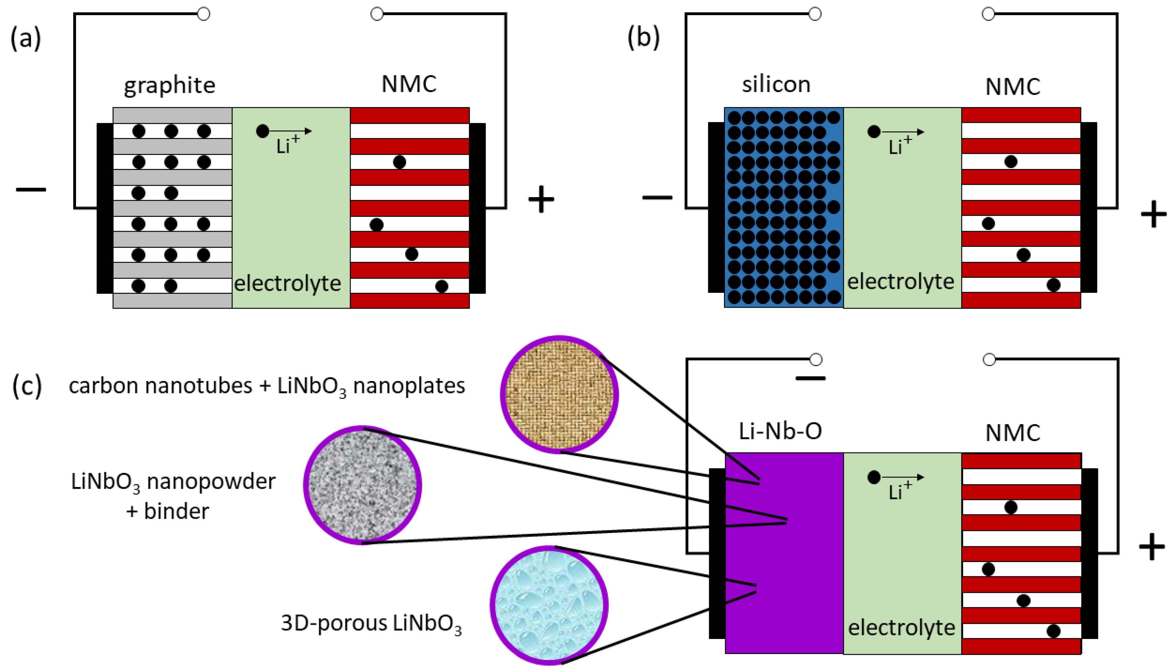
Figure 1. Schematized LIBs. The positive electrodes contain NMC. The negative electrode is (a) graphite, (b) silicon, and (c) Li-Nb-O with different structures. The indicated direction of Li-ion transport in the electrolyte refers to discharge. This figure appears in color online.
Batteries 09 00244 g001
Figure 2. Schematized LIBs with LiNbO3 insertion layers (marked in violet) between electrodes and electrolyte. The indicated direction of Li-ion transport in the electrolyte refers to discharge. This figure appears in color online. (a) LiNbO3 insertion layer situated solely at the positive electrode (here NMC). (b,c) LiNbO3 insertion layer situated solely at the negative electrode ((b) lithium, (c) silicon). (d) LiNbO3 insertion layers situated at the negative electrode (here lithium) and at the positive electrode (here NMC).
Batteries 09 00244 g002
Figure 3. (a,c) Measured (symbols) and simulated (continuous lines) neutron reflectometry patterns from (a) an amorphous LiNbO3 film deposited on a LiNbO3 crystal and that of a bare LiNbO3 crystal (black squares), and (c) an amorphous LiAlO2 film deposited on a LiAlO2 crystal and that of a bare LiAlO2 crystal (black squares). For clarity, the data are shifted in intensity. (b,d) Neutron scattering length density depth profiles corresponding to the NR simulations presented with continuous lines in (a,c), and of simulated bare 6LiNbO3 crystal (b) and bare 6LiAlO2 crystal (d). This figure appears in color online.
Batteries 09 00244 g003
Figure 4. (a) Cycle voltammetry (CV) of the first seven cycles of a 100 nm amorphous LiNbO3 film (sweep rate: 0.1 mVs−1). (b) CV of the first and second cycles of a 150 nm amorphous LiNbO3 film (sweep rate: 0.03 mVs−1). (c,d) Potential profile of the first five CC cycles of the 14 nm (c) and 140 nm (d) amorphous LiNbO3 film. The potential of the LiNbO3 film electrode (working electrode potential Ewe) is with respect to the potential of the Li-metal reference electrode. The cutoff potentials for CC cycles were set to 0.001 V and 2.9 V. The roman numerals I to VI mark predominant Li+ releases and Li+ uptakes and are explained in the text. This figure appears in color online.
Batteries 09 00244 g004
Figure 5. Potential resolved Li+ uptake and release from 14 nm (blue curves) and 140 nm (red curves) amorphous LiNbO3 film electrodes during CC cycling with a current density of 13 µAcm−2. The potential of the LiNbO3 film electrode (Ewe) is versus the potential of the Li-metal reference electrode. (a) dQ/dV and (b) dC/dV plot of the first cycle, (cf) dC/dV plot of the second (c), fifth (d), 45th (e), and 1279th (f) CC cycle. The roman numerals I to VI mark predominant Li+ releases and Li+ uptakes and are explained in the text. This figure appears in color online.
Batteries 09 00244 g005
Figure 6. (a) CV performed with different sweep-rates beyond the seventh cycle of a 100 nm amorphous LiNbO3 film to determine pseudocapacitive contribution. Potential resolved Li+ uptake and release from amorphous LiNbO3 films. (b) Percentage of pseudocapacitive behavior at different electrode potentials vs. Li metal reference electrode, determined from the CV measurements presented in (a). (cf) Peak current versus sweep rate (symbols) together with fits at different electrode potentials. This figure appears in color online.
Batteries 09 00244 g006
Figure 7. (a,b) EIS data obtained from the 100 nm amorphous LiNbO3 film, (a) before the first cycle and after the first delithiation, and (b) in the lithiated and delithiated state of the 14th cycle (i.e., after the last CV cycle of Figure 6), and of the 114th cycle (i.e., after the 14th CV cycles and after additional 100 CC cycles with 13 µA/cm2). The equivalent circuit is inserted in panel (b). (c) Li diffusivity obtained from the EIS data in lithiated and delithiated states versus cycle number. The blue-filled square at cycle number 118 was obtained on the 150 nm LiNbO3 film electrode. This figure appears in color online.
Batteries 09 00244 g007
Figure 8. Gravimetric capacity for Li+ release (violet squares) and Coulombic efficiency (green circles) of (a) 100 nm, (b) 150 nm, and (c) 140 nm amorphous LiNbO3 film electrodes versus cycle number. The capacity for Li+ insertion is obtained by dividing the release capacity by the Coulombic efficiency. This figure appears in color online.
Batteries 09 00244 g008
Figure 9. (a) Capacity for Li+ release (violet squares) and Coulombic efficiency (green circles) of a 14 nm amorphous LiNbO3 film electrode versus cycle number. For better visualization, only each eighth point is plotted. The vertical arrow indicates the capacity increase after 12 h OCV and subsequent cutoff potential readjustment to ensure lithiation up to Li-plating onset. The capacity for Li+ insertion can be obtained by dividing the release capacity by the Coulombic efficiency. (b) Potential resolved Li+ uptake and release from amorphous 14 nm LiNbO3 films for cycle number 46 to cycle number 346 with a current density of 388 µAcm−2, presented without overpotential correction shifts. The cutoff potentials were −0.23 V and 3.5 V, respectively. The oblique arrows indicate shifts due to increased overpotential. (c) dQ/dV curves of cycles 948 and 958 with a current density of 388 µAcm−2, performed before and behind the region marked with a vertical arrow in panel (b). The roman numerals I to VI mark predominant Li+ releases and Li+ uptakes and are explained in the text. This figure appears in color online.
Batteries 09 00244 g009
Table 2. Neutron scattering length density (second column), mass density (third column), and the fraction of the mass density of the amorphous film to the mass density of the corresponding crystal.
Sample aSLD (10−4 nm−2)Mass Density (gcm−3)ρamorphous-film/ρcrystal
natLiNbO3-wafer4.25 ± 0.204.60 ± 0.22--
natLiNbO3-film3.30 ± 0.073.60 ± 0.080.78
6LiNbO3-film3.90 ± 0.153.61 ± 0.140.78
natLiAlO2-wafer3.13 ± 0.172.61 ± 0.14--
6LiAlO2-film3.80 ± 0.122.43 ± 0.080.93
a The LiNbO3 and LiAlO2 films were deposited on natLiNbO3 and natLiAlO2 wafers, respectively.
Table 3. Reversible gravimetric and volumetric capacities of ion beam-sputtered amorphous film electrodes of LiNbO3 (from Figure 9a), silicon (non-published), carbon (from Ref. [27]), and germanium (non-published) at high cycle numbers and high current densities. The volumetric capacity of the film (seventh column) and the maximal possible volumetric capacity (eighth column) were calculated by multiplying the film mass density (sixth column) with the gravimetric capacity (fourth column) and the maximal possible gravimetric capacity (fifth column), respectively. The last column lists the theoretical volumetric capacity with corresponding references.
Amorphous
Film
Electrode
Cycle
Number
Current
Density
(µAcm−2)
Film
Gravimetric
Capacity
(mAhg−1)
Maximal
Gravimetric
Capacity
(mAhg−1) [Refs.]
Film Mass Density
(gcm−3)
Film volumetric
Capacity
(mAhcm−3)
Maximal
Volumetric capacity
(mAhcm−3)
Theoretical
Volumetric capacity
(mAhcm−3) [Refs.]
14 nm LiNbO3600388500402 [62,63,64,87]3.6180014471769 [64]
14 nm LiNbO3970388700402 [62,63,64,87]3.6252014471769 [64]
14 nm silicon60011633003579 [29,30,134,135,136,137,138]260071588322 [134,135,136]
16 nm carbon600116350372 [27]2100744833 [136]
16 nm germanium2601163201385 [139]48055407366 [139]
Disclaimer/Publisher’s Note: The statements, opinions and data contained in all publications are solely those of the individual author(s) and contributor(s) and not of MDPI and/or the editor(s). MDPI and/or the editor(s) disclaim responsibility for any injury to people or property resulting from any ideas, methods, instructions or products referred to in the content.