Article

Localized High-Concentration Electrolyte (LHCE) for Fast Charging Lithium-Ion Batteries

1
School of Information Science and Engineering, Ningbo University, 818 Fenghua Road, Jiangbei District, Ningbo 315211, China
2
Ningbo Institute of Materials Technology & Engineering Chinese Academy of Sciences, 1219 Zhongguan Road, Zhenhai District, Ningbo 315201, China
3
China Beacons Institute, University of Nottingham Ningbo China, 211 Xingguang Road, Ningbo 315100, China
*
Authors to whom correspondence should be addressed.
Batteries 2023, 9(3), 155; https://doi.org/10.3390/batteries9030155
Submission received: 30 January 2023 / Revised: 19 February 2023 / Accepted: 25 February 2023 / Published: 28 February 2023

Abstract

:
The solid electrolyte interphase (SEI) significantly influences the electrochemical performance of lithium-ion batteries. Traditional electrolytes, particularly ether electrolytes, make it challenging to form a stable SEI film, and the corresponding lithium-ion batteries frequently exhibit poor electrochemical performance. In this paper, we develop a stable SEI film to improve fast charging and cycle performance using a localized high concentration electrolyte (LHCE). A unique solvation sheath formed by the coordination of Li+, anion, and solvent in the LHCE caused the anion to migrate quickly to the surface of the graphite anode and decompose to form a LiF-rich SEI. A LHCE enabled the Li||C battery to maintain a capacity of 124 mAh g−1 at a rate of 5 C, and the capacity remained at 289 mAh g−1 after 150 cycles at a rate of 0.1 C, with a capacity retention rate of 73% and an average coulomb efficiency of about 99.8%, thus demonstrating excellent long-cycle performance. The LFP||Li battery capacity at a 5 C rate can also be maintained at 102 mAh g−1.

1. Introduction

In recent years, global climate change and the upsurge in energy demand have significantly contributed to developing new energy vehicles [1,2]. In comparison to fuel vehicles, new energy vehicles are more energy efficient, environmentally friendly, and inexpensive. Lithium-ion batteries, the most advanced portable energy storage devices, have been widely used in new energy vehicles [3]. However, short cruising ranges and long charging times have emerged as significant impediments to developing new energy vehicles. In order to achieve this objective, the U.S. Department of Energy has proposed the concept of “extreme fast charging” (XFC), which requires a 4 C multiplier to complete charging in 15 min, thereby ensuring the widespread adoption of electric vehicles [4,5,6]. The shortcomings of fast charging are predominantly attributable to the lithium precipitation of the negative electrode material. Fast charging confronts significant difficulties in the later stages of constant current charging of lithium-ion batteries due to uneven SEI film or unstable structure that increases the risk of lithium evolution and leads to poor battery cycle performance [7,8,9].
The electrolyte is a critical factor influencing the fast-charging performance of lithium-ion batteries. The electrolyte affects the operating voltage [10,11,12], electrochemical performance, operating temperature range, and safety performance of lithium-ion batteries [2,13,14]. Furthermore, the electrolyte reduction reaction on the electrode surface also affects the formation of the SEI film [15]. A stable SEI film avoids direct contact between the electrolyte and the graphite cathode, thus avoiding the continuous reductive decomposition of the electrolyte [16,17,18]. The lithium atoms on the positive electrode break down into Li+ and electrons during the charging process, as is illustrated in Figure 1 [19,20,21]. Electrons reach the negative electrode through an external circuit, whereas lithium-ions interact with the electrons at the negative electrode via the electrolyte [22,23,24,25]. The lithium ions interact with the electrons at the negative electrode, transforming the lithium-ions into lithium atoms. During the charging process, Li+ goes through three steps: (a) diffusion of the solventized Li+ in the electrolyte community; (b) desolvation of the solventized Li+ before crossing the SEI film; and (c) Li+ crossing the SEI film. When Li+ is embedded in the graphite anode, solvent molecules are co-embedded in the graphite interlayer, and the subsequent electrolyte decomposition can easily lead to the flaking of the graphite [26,27,28]. This is because the strong coordination between lithium-ions and solvent molecules makes it difficult to desolvate, while the weak van der Waals forces between graphite layers make it difficult to maintain the laminar structure of graphite despite the co-embedding of solvent molecules [29,30,31]. Therefore, regulating the solventized structure of the electrolyte and effectively inhibiting solvent molecule co-embedding is an effective method for improving the fast-charging performance of graphite [21,32,33,34]. As a result, a local high concentration electrolyte was selected to change the solvation structure in the electrolyte and achieve the fast-charging performance of lithium-ion batteries [35,36,37].
Designing the LHCE that is suitable for the fast charging of a lithium-ion battery mainly depends on three aspects: lithium salt, solvent, and diluent. The influence of the selection of lithium salt in the LHCE on the fast charging performance of the graphite negative electrode cannot be ignored. Studies have shown that, in conventional electrolytes, electrolytes containing lithium bis(fluorosulfonyl)imide (LiFSI) have higher conductivity than electrolytes containing other lithium salts (LiFSI > lithium hexafluorophosphate (LiPF6) > bistrifluoromethanesulfonimide lithium salt (LiTFSI) > lithium perchlorate (LiClO4) > lithium tetrafluoroborate (LiBF4)), and their fluorine content is lower and more environmentally friendly [32]. Therefore, LiFSI is regarded as the lithium salt with the most potential to replace LiPF6, especially in the field of fast-charging lithium-ion batteries. Additionally, the solubility and dissociation constant of conventional lithium salt cannot meet the requirements of the LHCE and HCE, while the lithium salt of FSI- can meet the requirements of the LHCE and HCE for lithium salt. Solvents used in conventional electrolytes (such as carbonates, carboxylates, ethers, phosphates, nitriles and sulfones) can be used for the HCE and LHCE. At the same time, because almost all solvents in the HCE and LHCE participate in Li+ coordination, the stability of the electrolyte is improved, so the selection of solvents in the LHCE is wider. Due to the introduction of diluents in the LHCE, the total lithium salt concentration in the HCE is reduced while retaining the special solvated sheath formed by the coordination of lithium salts and solvents in the HCE. Therefore, when selecting a diluent, lithium salt is required to have little or no solubility in this diluent. It is required that the diluent can be miscible with lithium salts and for solvents in the HCE to form a clear and homogeneous solution to avoid phase separation; in addition, the viscosity of the diluent should be low to reduce the overall viscosity of the electrolyte to have sufficient stability. Bis(2,2,2-trifluoroethyl) ether (BTFE), 1,1,2,2-tetrafluoroethyl-2,2,3,3-tetrafluoropropyl ether (TTE), etc. can meet the above requirements, so they can be used for the LHCE.

2. Experimental Procedure

2.1. Methods

The lithium salts LiPF6 and LiFSI were bought from Shanghai Aladdin Bio-Chem Technology Co., Ltd., whereas the solvents ethyl carbonate (EC), dimethyl carbonate (DMC), dimethoxyethane (DME), and TTE were from Shanshan Corporation. The electrolyte was prepared in the argon-filled glove box (MBRAUN, H2O < 0.1 ppm, O2 < 0.1 ppm) according to the ratios in Table 1, and then lithium salts of corresponding masses were added to form electrolytes of different concentrations [38,39].
The graphite anode was assembled by mixing the active material (graphite), conductive black carbon (Super P, Aladdin Bio-Chem Technology Co., Ltd., Shanghai, China), and polyvinylidene fluoride (PVDF, Aladdin Bio-Chem Technology Co., Ltd., Shanghai, China) in a mass ratio of 7:2:1. To make the slurry well mixed, an appropriate amount of N-methyl-2-pyrrolidone (NMP, DuoDuo Chemical Technology Co., Ltd., Suzhou, China) solvent was added and ball milled in a ball mill (QM-QX0.4L, Miqi Instrument Equipment Co., Ltd., Changsha, China) at 300 r/min for 3 h. The paste was coated on the copper foil with a thickness of 200 μm and then dried in an air-blowing thermostatic oven (DHG-9240A, Huitai Instrument Manufac-turing Co., Ltd., Shanghai, China) at 80 °C for 3 h. When the slurry on the surface was free of fluidity, it was transferred to a vacuum drying oven (DZF-6020,Huitai Instrument Manufacturing Co., Ltd., Shanghai, China) at 120 °C for 12 h. We completely removed the NMP and water from the pole piece and cut it into circular pieces of 14 mm diameter after cooling. The ferrous lithium phosphate (LiFePO4, LFP) cathode was assembled by mixing the active material LiFePO4, PVDF, and Super-P in a mass ratio of 8:1:1. Then an appropriate amount of NMP was added for ball milling. The obtained slurry was coated on aluminum foil. The subsequent steps were the same as those for graphite anode preparation.

2.2. Electrochemical Testing

Cyclic voltammetry (CV), the Tafel curve, linear sweep voltammetry (LSV), and electrochemical impedance spectroscopy (EIS) were tested by an electrochemical Workstation (CHI760E, Chenhua Instrument Co., Ltd., Shanghai, China). CV and EIS tests were performed using Li||C batteries. The LSV test was performed with Li||Stainless Steel (SS) batteries, while Li||Li batteries were used to test the Tafel curves. The CV test was conducted by sweeping at 0.5 mV/s in the voltage range of 0–3 V. The EIS tests were performed in the frequency range of 1 × 10⁻² to 1 × 10⁵ Hz, with a voltage disturbance of 5 mV. Li||C batteries were tested in the LAND system (CT2001A, LAND Electronics Co., Ltd., Wuhan, China) and used to compare the cyclic performance and rate performance. Long cycle performance was tested at 0.5 C scan rate over a voltage range of 0.05–1.5 V. To test the rate performance of the battery, 5 cycles were sustained at a rate of 0.5 C, 1 C, 2 C, 3 C, 4 C, 5 C, 4 C, 3 C, 2 C, 1 C, 0.5C in the voltage range of 0.05–1.5 V.

2.3. AFM Measurements

These measurements combined the electrochemical workstation with atomic force microscopy (AFM, Icon, Bruker Corporation, Billerica, MA, USA). The SEI film morphology of highly-ordered pyrolytic graphite (HOPG, Bruker Corporation, Billerica, MA, USA, 12 × 12 × 2 mm) surfaces in different concentrations of electrolytes was observed using electrochemical atomic force microscopy (EC-AFM). The electrochemical cell was first assembled with lithium strips as the reference and counter electrodes (RE and CE), respectively, and the HOPG was connected to the working electrode (WE) by a conductive metal spring. After the CV cycle, the SEI film morphology of the HOPG surface was observed. The AFM mode selected was ScanAsyst in fluid mode, and the SCANNASYST-FLUID+ probe was employed to observe the sample morphology, imaging at a scan rate of 1.0 Hz and a resolution of 256 × 256 pixels, with the scanning range set to 5 × 5 μm. The AFM was then switched to contact mode, a 2 × 2 μm area was selected, and the SEI film was scraped off. Then, we returned to ScanAsyst in fluid mode, and the scanning range was set to 5 × 5 μm to analyze the thickness of the SEI film. The above steps were performed in the argon-filled glove box.

2.4. Materials Characterization

Graphite was removed from the Li||C battery after three charge/discharge cycles, and the samples were rinsed several times with DME and DMC to remove residual solvents and lithium salts. The composition of the SEI film on the graphite cathode surface after cycling was investigated using X-ray photoelectron spectroscopy (XPS, Kratos AXIS Ultra DLD, Kratos, Manchester, UK).

3. Results and Discussion

3.1. CV Tests

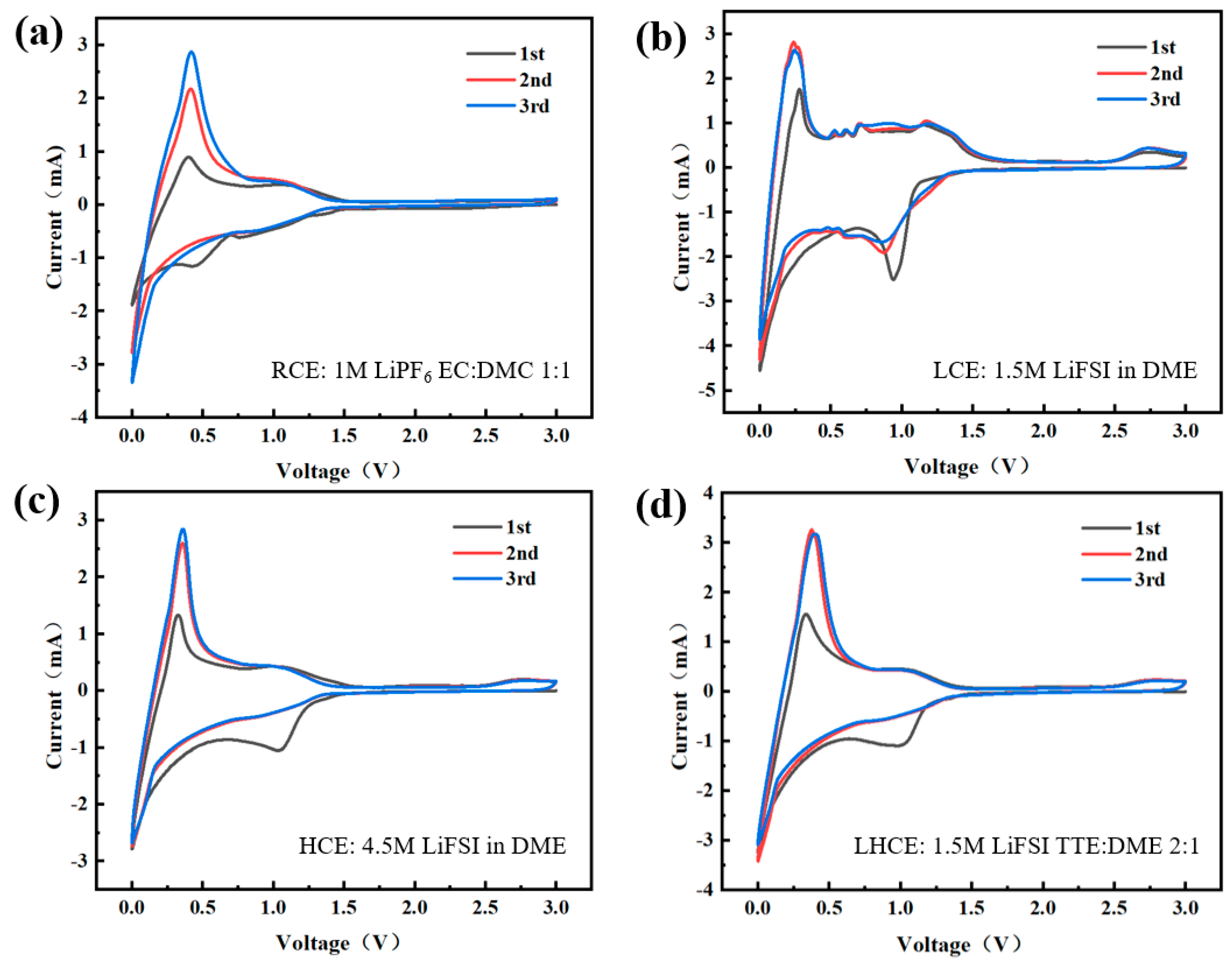
Figure 2a depicts the CV of the Li||C batteries in the RCE. The first small reduction peak appeared at about 0.8 V and disappeared in subsequent cycles. This was due to the beginning of the decomposition of solvent molecules in the electrolyte. The second large reduction peak appeared near 0.5 V and was attributed to the involvement of the anion in the redox reaction, which is relatively violent, whereas the reduction peak near 0 V was assigned to lithium intercalation in graphite. Figure 2b–d demonstrate the CV of assembled Li||C batteries with three different electrolyte concentrations, all exhibiting more typical characteristics. The reduction peak around 1.0 V corresponded to irreversible electrolyte decomposition and the formation of the negative SEI film, and it weakened or even disappeared in the subsequent two cycles. The reduction peak around 0 V corresponded to the process of lithium insertion in the negative electrode, while the prominent oxide peak around 0.3 V represents the process of lithium intercalation.
Figure 3a compares the first CV cycle of the RCE, LCE, HCE, and LHCE in Li||C batteries. By comparing the positions of reduction peaks for four electrolytes, the reduction potentials of LHCE, HCE, LCE, and RCE were 1.023 V, 1.053 V, 0.944 V, and 0.454 V, respectively. The anion in the LHCE reached its decomposition voltage more easily than the RCE. Thus, the solvent molecules in the electrolyte were preferentially decomposed to form a SEI film dominated by inorganic compounds. In the LHCE, aggregated clusters (AGG, anion corresponding to two or more Li+ cations) and contact ion pairs (CIP, anion coordinating to a single Li+ cation) allowed rapid migration of the FSI- from the electrolyte to the graphite anode surface and reductive decomposition [30].

3.2. Electrochemical Impedance Tests

The impedance in the mid-frequency and high-frequency regions is expressed as charge diffusion impedance Rct and the interface film impedance RSEI, respectively, as are displayed in Figure 3b,c. Graphite had the highest impedance value in the RCE before and after the three CV cycles, which corresponded to the most considerable interfacial film thickness value in EC-AFM observation. Table 2 displays the specific impedance values. The SEI film formed in the LHCE had the lowest impedance, thus indicating that it is more conductive than other electrolytes.

3.3. The Tafel Curve

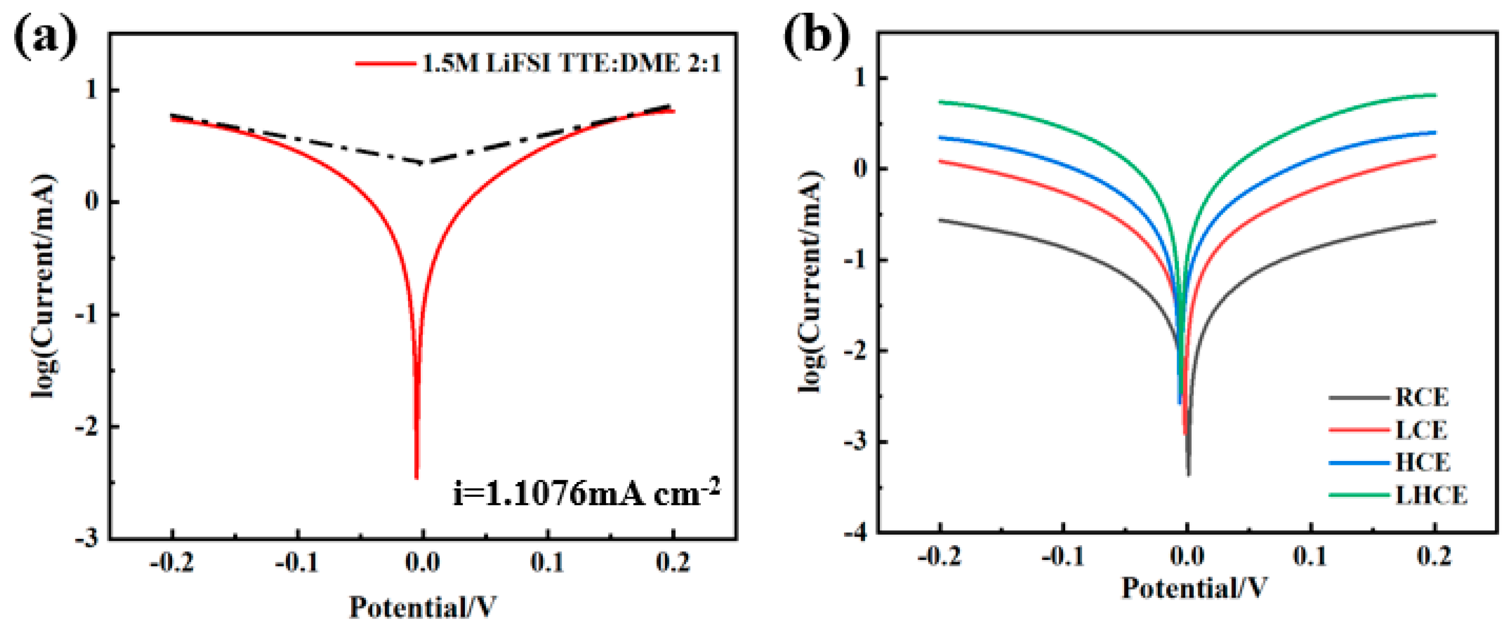
Figure 4 and Figure S1 show the Tafel curve of Li||Li batteries. The exchange current density of the LHCE (1.1076 mA cm−2) was calculated to be significantly higher than that of the RCE (0.0858 mA cm−2) It was confirmed that the SEI film Li+ generated in the LHCE had higher conductivity and faster charge transfer ability.

3.4. Cyclic Performance

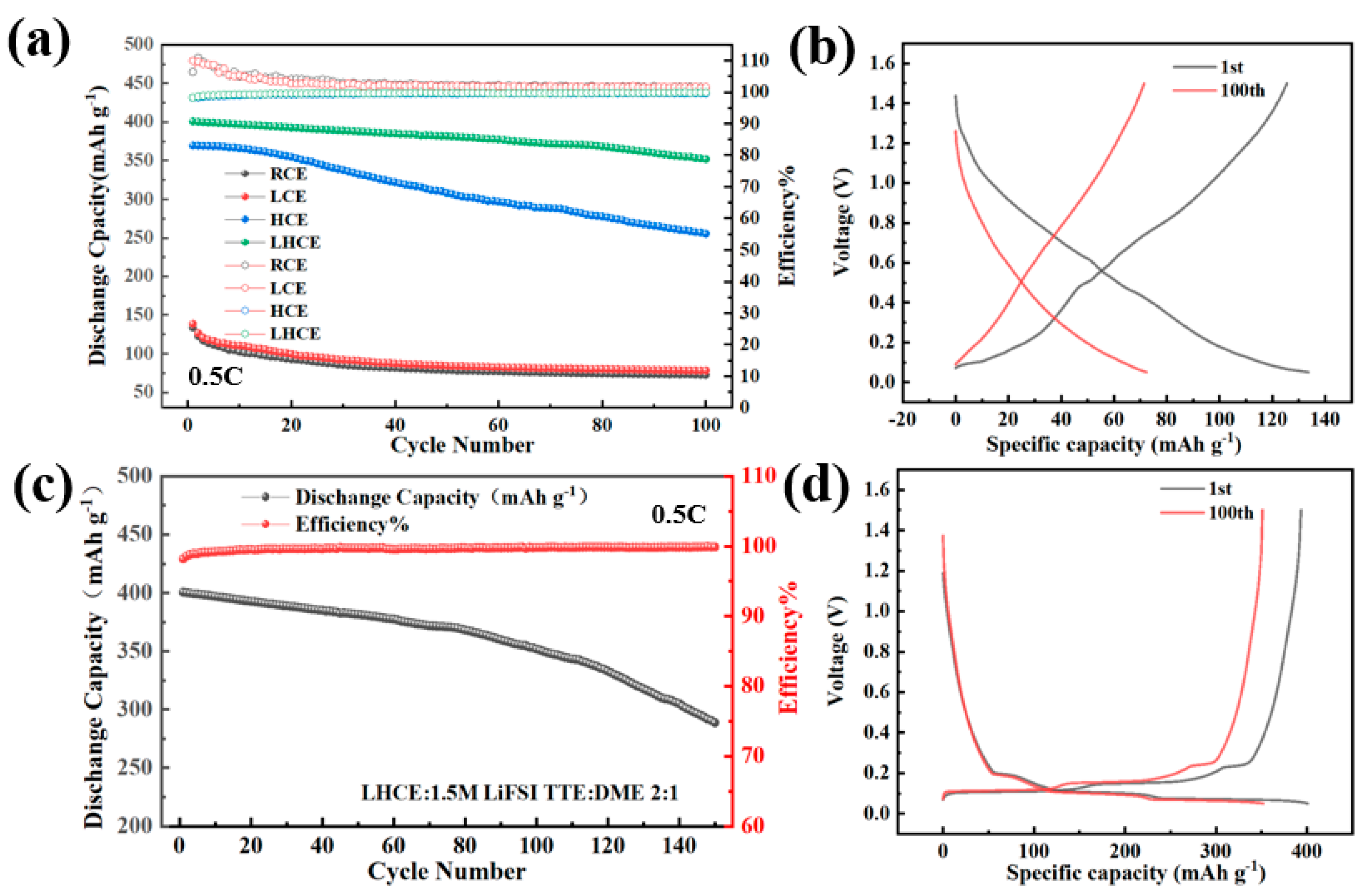
The first cycle capacity of the RCE-assembled batteries was only 134 mAh g−1, the capacity attenuation after 100 charge-discharge cycles was 72 mAh g−1, and the capacity retention rate was only 53.73%, as are depicted in Figure 5a and Figure S2. The capacity retention rate of the LCE-assembled batteries was only 56% due to the problem of Li+ co-intercalation, which caused later graphite shedding, resulting in battery capacity decay and reduced cycle stability. However, after 150 long cycles, the capacity of the LHCE assembled battery remained at 289 mAh g−1, the capacity retention rate reached 73%, and the average coulombic efficiency was approximately 99.8%, thus demonstrating excellent long cycle performance (Figure 5c). This reveals that the LHCE can form a stable SEI film at the interface, which plays the role of passivating the adverse reaction of the interface and thereby improving the overall performance of the battery. The capacity-voltage curves in Figure 5b,d and Figure S3 reflect the capacity retention of the four electrolytes for 100 cycles.

3.5. Rate Performance Tests

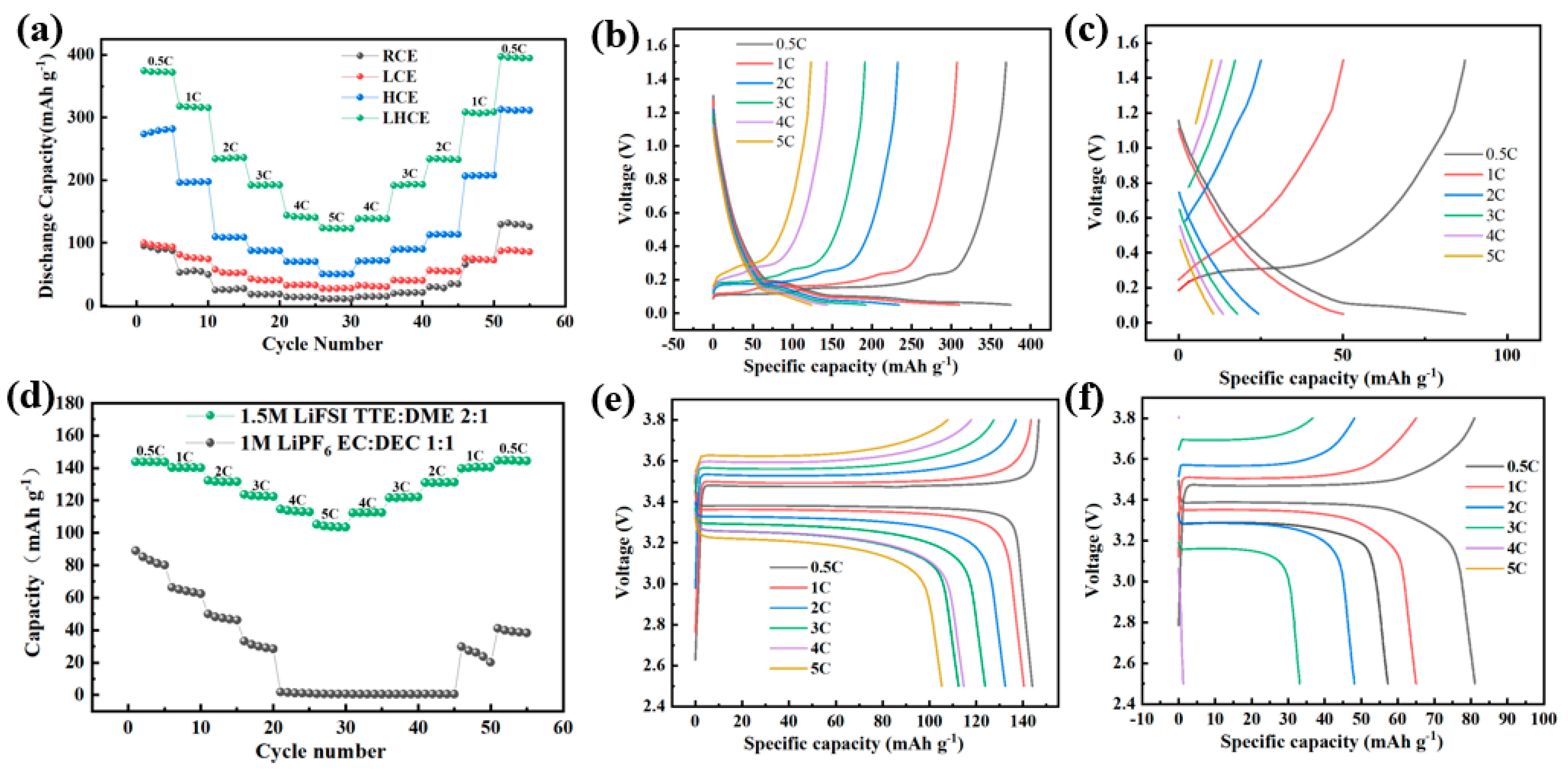
The rate performance of the Li||C batteries demonstrates the advantages of the LHCE, as is shown in Figure 6a. The assembled LHCE batteries had specific discharge capacities of 370, 310, 234, 192, 144, and 124 mAh g−1, from 0.5 C to 5 C, respectively. The initial capacity of the RCE-assembled batteries was significantly lower than that of the LHCE; RCE-assembled batteries had a capacity of only 10 mAh g−1 at 5 C. As illustrated in Figure 6b,c and Figure S4, when the multiplicity increases from 1 C to 5 C, the overpotential of the negative graphite terminal in the LHCE increased from 0.0873 to 0.1609 V, which was much lower than that in the RCE (from 0.1845 to 1.1381 V). At low rates (<1 C), the Li+ embedding kinetics were almost independent of the electrolyte, and the capacity–voltage distribution curves of the LHCE and RCE were similar. When the rate was increased to 5 C, the cells of the two electrolytes displayed a significant difference, particularly in the capacity voltage distribution. At high rates, batteries assembled using the LHCE exhibited a more pronounced voltage plateau and lower overpotential.
Figure 6d compares the rate performance of the LFP||Li batteries; in the LHCE, the initial capacity at 0.5 C was 145 mAh g−1, and the capacity at 5 C could also be maintained at 102 mAh g−1, whereas the typical commercial electrolyte, with an initial capacity of 89 mAh g−1 at 0.5 C, had a capacity of 0 mAh g−1 at 4 C. When the current density was reduced from 5 C, the commercial electrolyte-assembled battery had a much lower specific capacity than the initial 0.5 C discharge specific capacity, whereas the LHCE-assembled battery recovered the initial 0.5 C discharge specific capacity when the current density was reduced back to 0.5 C. The capacity-voltage curves also showed that the cells assembled with the LHCE exhibited a more pronounced voltage plateau at high magnification (Figure 6e,f). All of these results demonstrate the superior rate performance of the LHCE-assembled batteries.

3.6. EC-AFM of Different Electrolytes on HOPG

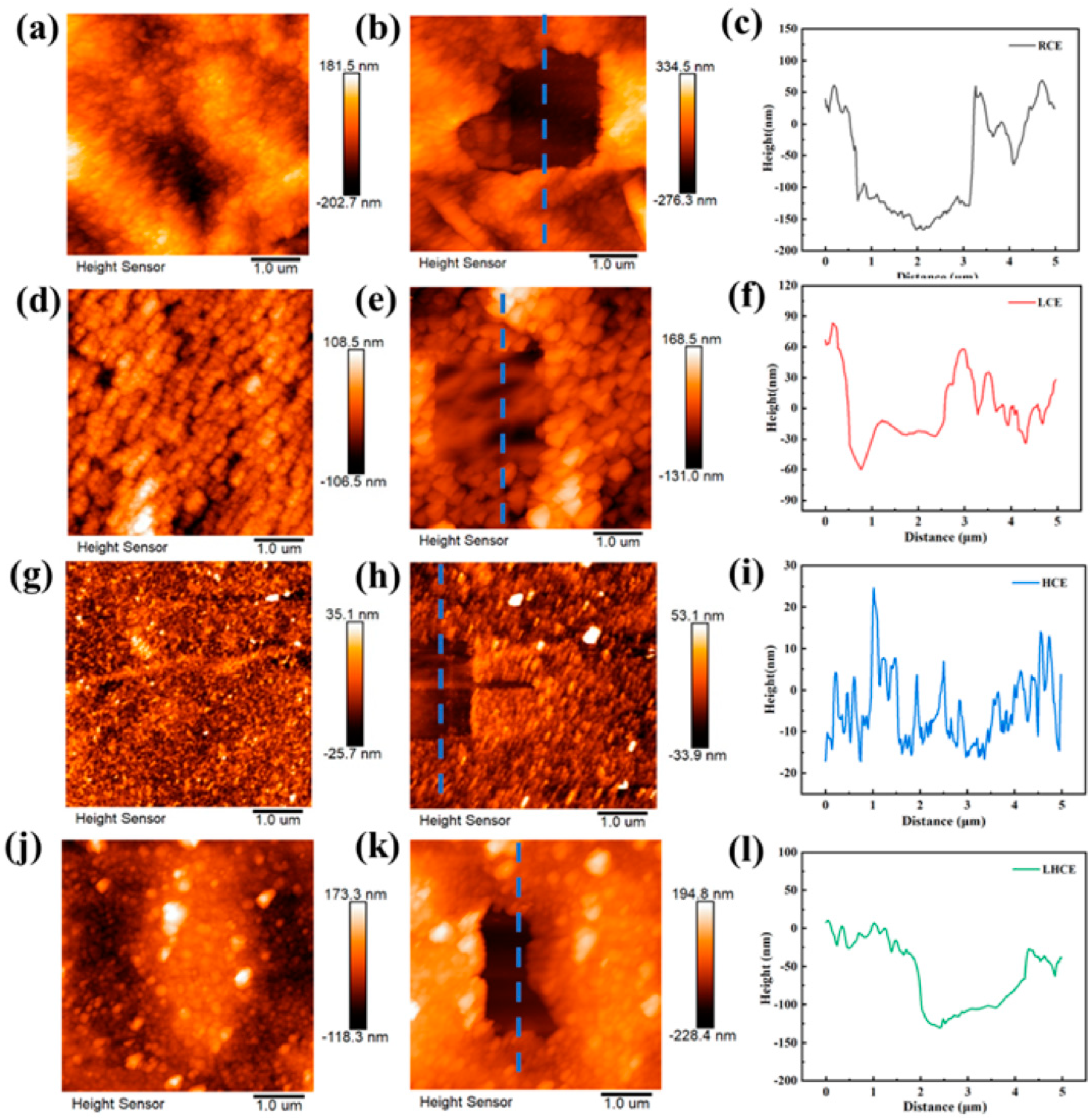
Figure 7 depicts the morphology of the SEI film generated on HOPG by the four electrolytes using EC-AFM. In-situ EC-AFM observations are challenging due to the following factors: (1) The addition of diluent causes the LHCE electrolyte to volatilize quickly in a non-closed electrochemical cell; (2) The lithium salt concentration of HCE is too high, leading to the high viscosity of the electrolyte; (3) During the cycle of LCE, the reaction is intense and the morphology changes quickly, which results in cracks on the surface of subsequent samples.
After the CV was completed, the SEI film was scraped off using the contact mode of EC-AFM to determine the film thickness. The SEI film formed by the RCE was not uniform and had a soft texture (Figure 7a), and the thickness of the SEI film was measured to be about 200 nm after scraping at 10 V (Figure 7c). The thick SEI film will lead to an excessive impedance of the interfacial film. The SEI film formed by the LCE was also inhomogeneous (Figure 7d), but the thickness of the film after scraping was about 60 nm (Figure 7f), which was significantly less than the thickness of the SEI film formed by the RCE. The too-thin SEI film cannot protect the negative graphite electrode, thus allowing Li+ co-embedding in the LCE and resulting in graphite flaking. The delamination of the HOPG can be observed in the optical microscope diagram of the HOPG after cycling (Figure 8a), and the abnormal bulge on the side indicates that a large number of Li+ was co-embedded with solvent molecules, thus increasing the spacing of the graphite layers and resulting in peeling of the graphite layer. Compared to the RCE and LCE, the SEI film formed by the HCE and LHCE was relatively uniform, had a harder texture, and possessed greater mechanical strength (Figure 7g–i), but the HCE performed moderately less than the LHCE in an electrochemical performance test. The thickness of the SEI film formed by the LHCE was moderate, approximately 120 nm (Figure 7l), and the HOPG preservation after cycling was relatively complete (Figure 8b), thus enabling it to exhibit the best electrochemical performance. Moreover, when the SEI film formed by the RCE was scraped with a voltage of 5 V (Figure S5), a large area of the SEI film was scraped off, while only a part of the SEI film formed by the LHCE was scraped off, thus demonstrating that the mechanical strength of the SEI film formed by LHCE was superior to that of the SEI film formed by the RCE. As is seen in the Figure S6, the electrochemical stability window exhibited by RCE was only 4.2 V, while that of the LHCE increased to 5.1 V. This confirms the good film forming effect and excellent antioxidant property of the LHCE.

3.7. XPS Analysis

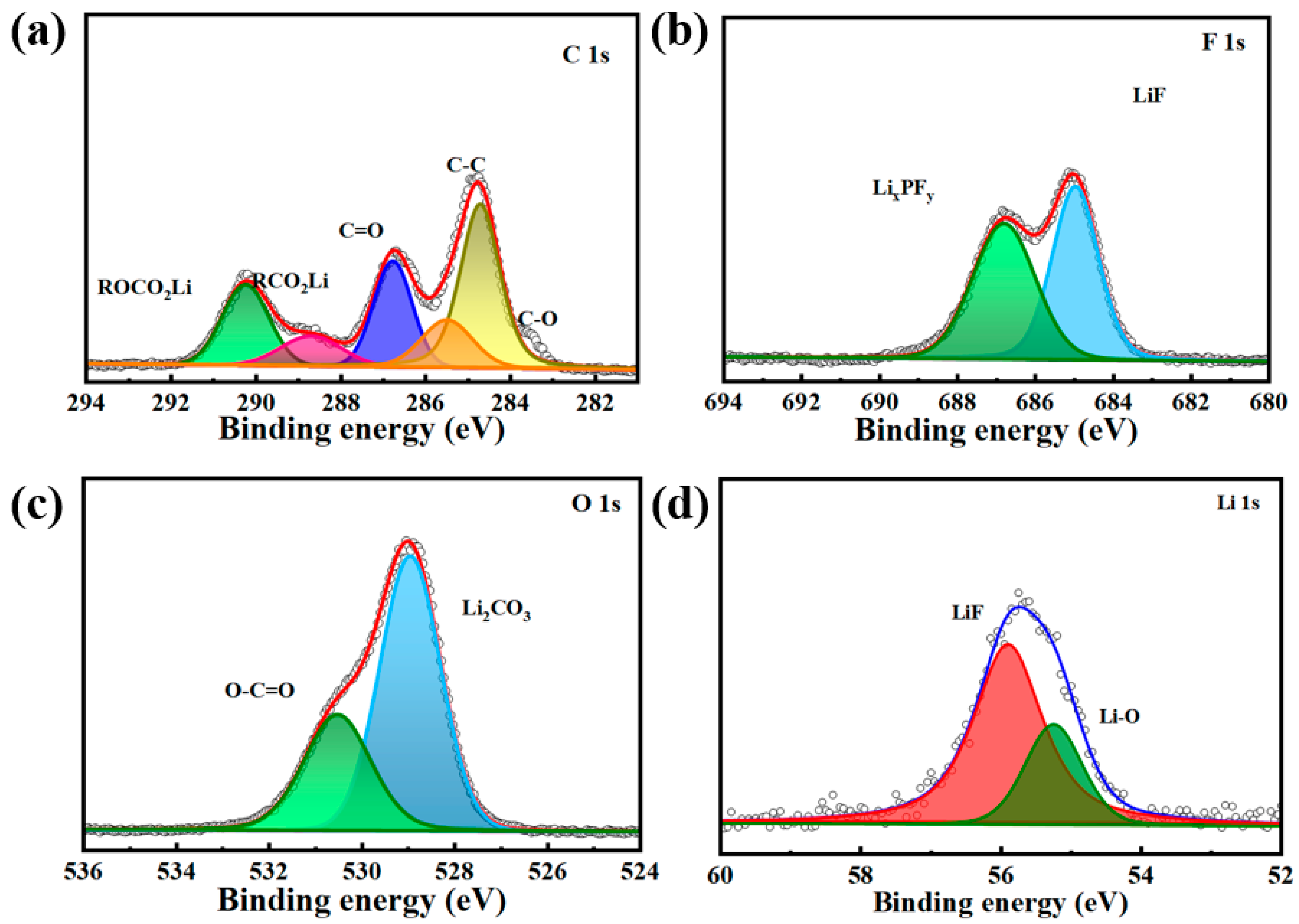
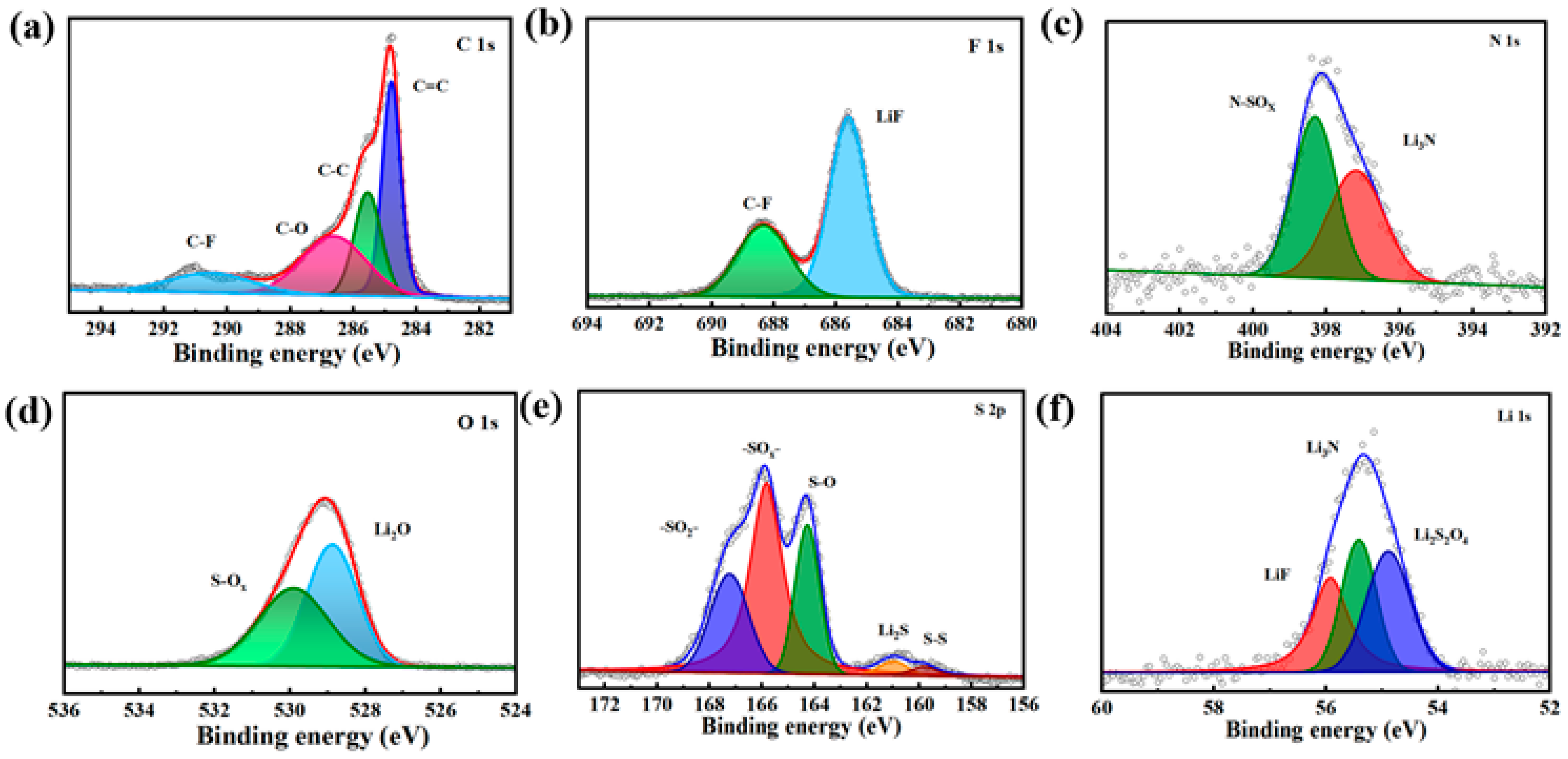
For SEI films formed in the RCE (Figure 9), the organic species ROCO2Li and RCO2Li were detected at around 290.3 eV and 288.7 eV, respectively, in the C 1s spectrum (Figure 9a). The peak in the F 1s spectrum around 686.8 eV was derived from the LixPFy produced by the decomposition of LiPF6, and the LiF signal of the inorganic species was observed at about 685 eV (Figure 9b). In the O 1s spectrum, the signal detected in the inorganic was located at about 529 eV in Figure 9c. LiF and Li-O were also detected in the Li 1s spectra at 55.9 eV and 55.2 eV, respectively (Figure 9d). According to the XPS elemental analysis of the SEI membrane formed by the RCE, the composition of the SEI membrane was dominated by carbon species (Figure 9a), thus indicating that most of the components of this SEI membrane were derived from EC decomposition. At the same time, signals from LiF and other inorganic species were relatively weak. It was shown that the SEI membrane formed in the RCE was rich in organic matter. SEI films formed in the LHCE, where the compound of the C-O bond (286.7 eV) was relatively low in the C 1s spectrum (Figure 10a). The SEI film formed by the LHCE contained fewer organic components, thus indicating that the decomposition of DME had not yet taken place. It shows that AGG-driven anions can quickly migrate to the graphite surface and decompose to form a large amount of LiF (Figure 10b). LiF-rich SEI film can substantially improve the stability of the electrode interface. The peak of the N 1s spectrum at approximately 398.3 eV was caused by N-SOx produced by the FSI incomplete decomposition, while the peak at around 397.57 eV was induced by Li3N (Figure 10c). There were also clear signals from S-Ox species observed at 529.9 and 165.8 eV, respectively, in the O 1s and S 2p spectra (Figure 10d,e), mainly from the further decomposition of FSI anions. The inorganic species Li2O and Li2S were detected at 528.9 and 161 eV, respectively. In addition, these inorganic species were detectable in the Li 1s spectrum (Figure 10f). The composition of the SEI membrane formed by the LCE and HCE was similar to that of the SEI film formed by the LHCE (Figure S7). Since the SEI film generated by the RCE is primarily composed of organic components and the analysis results of XPS corresponded to the EC-AFM test results, the texture of the SEI film was soft. Because the SEI film formed by the LHCE was mainly composed of organic matter, its mechanical strength was superior.
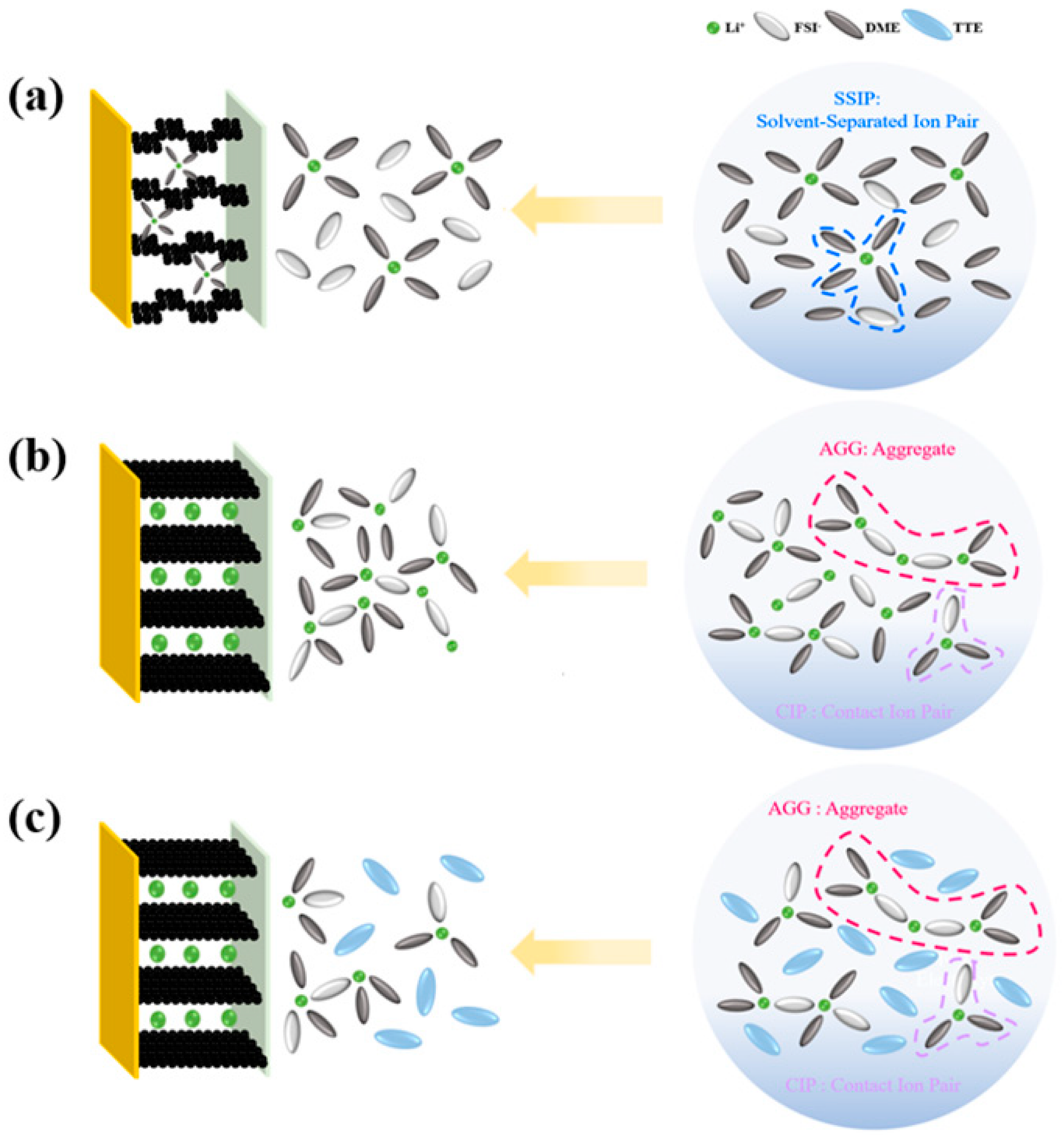
The conventional electrolyte has a lithium salt concentration of about 1 M, and a single Li+ can solvate with multiple solvent molecules (typically four to six) while the anion and the remaining solvent molecules are free to move [30]. In the conventional LCE, as is shown in Figure 11a, Li+ was solventized by a large amount of solvent, which formed a solvent-separated ion pair (SSIP) structure. When Li+ was embedded in the negative graphite electrode, the strong chemical coordination between the ether solvent and Li+ made it challenging to desolvate the ether solvent and easy to form a co-intercalation layer, and the subsequent decomposition could easily lead to structural stripping of graphite, which eventually resulted in capacity decay and cycling instability. As is illustrated in Figure 11b, almost all solvent molecules were involved in the solemnization of Li+ in the HCE (typically lithium salt concentrations > 3 M), and anions were also engaged in the solemnization process, forming AGG and CIP, which resulted in little or no free solvent molecules in the HCE. However, the aggregation network structure in the HCE caused an increase in the viscosity of the electrolyte, a slowdown in the movement of ions in the electrolyte, a deterioration in wettability, and a reduction in ionic conductivity. These inadequacies have a substantial influence on the electrochemical performance of lithium batteries [40].
As is shown in Figure 11c, the LHCE was produced by diluting the HCE with a diluent that did not dissolve the lithium salt. The reduced lithium salt content per unit volume resulted in the formation of a localized high concentration lithium salt state, which not only preserved the unique solventized sheath formed by the coordination of Li+ with salt and solvent in the HCE, but also improved the electrolyte’s conductivity and ability to wet the electrode surface, thus resulting in good electrochemical performance of the LHCE.

4. Conclusions

We summarized and compared the research progress of the LHCE (Table S1) [30,41,42,43,44,45,46,47,48]. A stable SEI film was successfully constructed using the LHCE electrolyte, which led to improved cycle performance and fast charging performance for the corresponding battery. The SEI film formed by the designed LHCE exhibited higher interfacial stability and stronger Li+ transport capacity, thus enabling it to maintain excellent cycling capacity, a higher capacity retention rate, and a higher charge-discharge rate according to the electrochemical test. EC-AFM and XPS analysis revealed that the SEI film formed in the LHCE was not only moderately thick, dense, uniform, and hard, but also rich in inorganic salts, such as LiF, that were conducive to Li+ transport, which was the leading factor for its excellent electrochemical performance.

Supplementary Materials

The following supporting information can be downloaded at: https://www.mdpi.com/article/10.3390/batteries9030155/s1, Figure S1. Tafel curves of Li||Li batteries in different electrolytes. (a) RCE, (b) LCE, (c) HCE; Figure S2. Cycle performance of Li||C batteries in different electrolytes. (a) RCE, (b) LCE, (c) HCE; Figure S3. Capacity-voltage curves of Li||C batteries cycled in different electrolytes for the 1st and 100th cycles. (a) LCE, (b) HCE; Figure S4. Capacity-voltage curves of Li||C batteries in different electrolytes at different rates. (a) LCE, (b) HCE, (c) Capacity-voltage curves of Li||C batteries in four electrolytes at 5C rate; Figure S5. The SEI film appearance was removed by the AFM tip with a force of 5V. (a) RCE, (b) LHCE; Figure S6. LSV curves of two electrolytes; Figure S7. XPS analysis of graphite anode after three cycles in electrolyte. (a) LCE, (b) HCE; Table S1. Research progress and comparison of LHCE.

Author Contributions

Conceptualization, C.S.; Methodology, J.Y. and C.S.; Software, J.Y.; Validation, J.Y., X.S. and W.W.; Formal analysis, J.Y. and C.S.; Investigation, J.Y. and C.S.; Resources, Z.L. and C.S.; Writing—review & editing, J.Y. and C.S.; Visualization, C.S.; Supervision, C.S.; Project administration, Z.L. and C.S.; Funding acquisition, C.S. All authors have read and agreed to the published version of the manuscript.

Funding

We are grateful for the financial support from the National Natural Science Foundation of China (Grant No. U2032126 and 22175192), and are grateful to the Ningbo Natural Science Foundation (2021J224) for financial support.

Data Availability Statement

Not applicable.

Conflicts of Interest

The authors declare no conflict of interest.

References

  1. Cai, W.; Yao, Y.-X.; Zhu, G.-L.; Yan, C.; Jiang, L.-L.; He, C.; Huang, J.-Q.; Zhang, Q. A review on energy chemistry of fast-charging anodes. Chem. Soc. Rev. 2020, 49, 3806–3833. [Google Scholar] [CrossRef] [PubMed]
  2. Yao, Y.; Chen, X.; Yao, N.; Gao, J.; Xu, G.; Ding, J.; Song, C.; Cai, W.; Yan, C.; Zhang, Q. Unlocking Charge Transfer Limitations for Extreme Fast Charging of Li-Ion Batteries. Angew. Chem. Int. Ed. 2022, 62, e202214828. [Google Scholar]
  3. Chu, Y.; Shen, Y.; Guo, F.; Zhao, X.; Dong, Q.; Zhang, Q.; Li, W.; Chen, H.; Luo, Z.; Chen, L. Advanced Characterizations of Solid Electrolyte Interphases in Lithium-Ion Batteries. Electrochem. Energy Rev. 2019, 3, 187–219. [Google Scholar] [CrossRef]
  4. Du, Z.; Wood, D.L., III; Belharouak, I. Enabling fast charging of high energy density Li-ion cells with high lithium ion transport electrolytes. Electrochem. Commun. 2019, 103, 109–113. [Google Scholar] [CrossRef]
  5. Ahmed, S.; Bloom, I.; Jansen, A.N.; Tanim, T.; Dufek, E.J.; Pesaran, A.; Burnham, A.; Carlson, R.B.; Dias, F.; Hardy, K.; et al. Enabling fast charging—A battery technology gap assessment. J. Power Sources 2017, 367, 250–262. [Google Scholar] [CrossRef]
  6. Cai, W.; Yan, C.; Yao, Y.; Xu, L.; Chen, X.; Huang, J.; Zhang, Q. The Boundary of Lithium Plating in Graphite Electrode for Safe Lithium-Ion Batteries. Angew. Chem. Int. Ed. 2021, 60, 13007–13012. [Google Scholar] [CrossRef]
  7. Liu, Y.; Zhu, Y.; Cui, Y. Challenges and opportunities towards fast-charging battery materials. Nat. Energy 2019, 4, 540–550. [Google Scholar] [CrossRef]
  8. Michelbacher, C.; Ahmed, S.; Bloom, I.; Burnham, A.; Carlson, B.; Dias, F.; Dufek, E.J.; Jansen, A.N.; Keyser, M.; Markel, A.; et al. Enabling fast charging—Introduction and overview. J. Power Sources 2017, 367, 214–215. [Google Scholar] [CrossRef]
  9. Mussa, A.; Klett, M.; Behm, M.; Lindbergh, G.; Lindström, R. Fast-charging to a partial state of charge in lithium-ion bat-teries: A comparative ageing study. J. Energy Storage 2017, 13, 325–333. [Google Scholar] [CrossRef]
  10. Jiang, L.; Dong, D.; Lu, Y.-C. Design strategies for low temperature aqueous electrolytes. Nano Res. Energy 2022, 1, e9120003. [Google Scholar] [CrossRef]
  11. Yang, J.; Hou, W.; Pan, R.; Zhou, M.; Zhang, S.; Zhang, Y. The interfacial electronic engineering in polyhedral MOF derived Co-doped NiSe2 composite for upgrading rate and longevity performance of aqueous energy storage. J. Alloys Compd. 2022, 897, 163187. [Google Scholar] [CrossRef]
  12. Ye, H.; Li, Y. Towards practical lean-electrolyte Li–S batteries: Highly solvating electrolytes or sparingly solvating electro-lytes? Nano Res. Energy 2022, 1, 9120012. [Google Scholar] [CrossRef]
  13. Sun, C.; Ji, X.; Weng, S.; Li, R.; Huang, X.; Zhu, C.; Xiao, X.; Deng, T.; Fan, L.; Chen, L.; et al. 50C Fast-Charge Li-Ion Batteries using a Graphite Anode. Adv. Mater. 2022, 34, e2206020. [Google Scholar] [CrossRef]
  14. Yang, L.; Cheng, X.; Gao, Y.; Ma, Y.; Zuo, P.; Du, C.; Cui, Y.; Guan, T.; Lou, S.; Wang, F.; et al. Lithium deposition on graphite anode during long-term cycles and the effect on capacity loss. RSC Adv. 2014, 4, 26335–26341. [Google Scholar] [CrossRef]
  15. Chen, H.; Tu, H.; Hu, C.; Liu, Y.; Dong, D.; Sun, Y.; Dai, Y.; Wang, S.; Qian, H.; Lin, Z.; et al. Cationic Covalent Organic Framework Nanosheets for Fast Li-Ion Conduction. J. Am. Chem. Soc. 2018, 140, 896–899. [Google Scholar] [CrossRef] [PubMed]
  16. Zhang, X.; Zou, L.; Cui, Z.; Jia, H.; Engelhard, M.H.; Matthews, B.E.; Cao, X.; Xie, Q.; Wang, C.; Manthiram, A.; et al. Stabilizing ultrahigh-nickel layered oxide cathodes for high-voltage lithium metal batteries. Mater. Today 2021, 44, 15–24. [Google Scholar] [CrossRef]
  17. Sun, Q.; Xi, B.; Li, J.-Y.; Mao, H.; Ma, X.; Liang, J.; Feng, J.; Xiong, S. Nitrogen-Doped Graphene-Supported Mixed Transi-tion-Metal Oxide Porous Particles to Confine Polysulfides for Lithium-Sulfur Batteries. Adv. Energy Mater. 2018, 8, 1800595. [Google Scholar] [CrossRef]
  18. Okoshi, M.; Yamada, Y.; Yamada, A.; Nakai, H. Theoretical Analysis on De-Solvation of Lithium, Sodium, and Magnesium Cations to Organic Electrolyte Solvents. J. Electrochem. Soc. 2013, 160, A2160–A2165. [Google Scholar] [CrossRef]
  19. Zhang, S.S. Challenges and Strategies for Fast Charge of Li-Ion Batteries. Chemelectrochem 2020, 7, 3569–3577. [Google Scholar] [CrossRef]
  20. Zhang, S. Identifying rate limitation and a guide to design of fast-charging Li-ion battery. InfoMat 2019, 2, 942–949. [Google Scholar] [CrossRef] [Green Version]
  21. Zhang, D.; Li, L.; Zhang, W.; Cao, M.; Qiu, H.; Ji, X. Research progress on electrolytes for fast-charging lithium-ion batteries. Chin. Chem. Lett. 2023, 34, 107122. [Google Scholar] [CrossRef]
  22. Cao, X.; Gao, P.; Ren, X.; Zou, L.; Engelhard, M.H.; Matthews, B.E.; Hu, J.; Niu, C.; Liu, D.; Arey, B.W.; et al. Effects of fluorinated solvents on electrolyte solvation structures and electrode/electrolyte interphases for lithium metal batteries. Proc. Natl. Acad. Sci. USA 2021, 118, e2020357118. [Google Scholar] [CrossRef] [PubMed]
  23. Yan, S.; Chen, X.; Zhou, P.; Wang, P.; Zhou, H.; Zhang, W.; Xia, Y.; Liu, K. Regulating the growth of lithium dendrite by coat-ing an ultra-thin layer of gold on separator for improving the fast-charging ability of graphite anode. J. Energy Chem. 2022, 67, 467–473. [Google Scholar] [CrossRef]
  24. Wu, Y.; Wang, W.; Ming, J.; Li, M.; Xie, L.; He, X.; Wang, J.; Liang, S.; Wu, Y. An Exploration of New Energy Storage System: High Energy Density, High Safety, and Fast Charging Lithium Ion Battery. Adv. Funct. Mater. 2019, 29, 1805978. [Google Scholar] [CrossRef] [Green Version]
  25. Wassiliadis, N.; Schneider, J.; Frank, A.; Wildfeuer, L.; Lin, X.; Jossen, A.; Lienkamp, M. Review of fast charging strategies for lithium-ion battery systems and their applicability for battery electric vehicles. J. Energy Storage 2021, 44, 103306. [Google Scholar] [CrossRef]
  26. Tomaszewska, A.; Chu, Z.; Feng, X.; O’Kane, S.; Liu, X.; Chen, J.; Ji, C.; Endler, E.; Li, R.; Liu, L.; et al. Lithium-ion battery fast charging: A review. eTransportation 2019, 1, 100011. [Google Scholar] [CrossRef]
  27. Rodrigues, M.-T.F.; Kalaga, K.; Trask, S.E.; Dees, D.W.; Shkrob, I.A.; Abraham, D.P. Fast Charging of Li-Ion Cells: Part I. Using Li/Cu Reference Electrodes to Probe Individual Electrode Potentials. J. Electrochem. Soc. 2019, 166, A996–A1003. [Google Scholar] [CrossRef]
  28. Zhu, G.; Zhao, C.; Huang, J.; He, C.; Zhang, J.; Chen, S.; Xu, L.; Yuan, H.; Zhang, Q. Fast Charging Lithium Batteries: Recent Progress and Future Prospects. Small 2019, 15, e1805389. [Google Scholar] [CrossRef]
  29. Xu, S.; Peng, B.; Pang, X.; Huang, F. Anionic Activity in Fast-Charging Batteries: Recent Advances, Prospects, and Challenges. ACS Mater. Lett. 2022, 4, 2195–2209. [Google Scholar] [CrossRef]
  30. Jiang, L.; Yan, C.; Yao, Y.; Cai, W.; Huang, J.; Zhang, Q. Inhibiting Solvent Co-Intercalation in a Graphite Anode by a Localized High-Concentration Electrolyte in Fast-Charging Batteries. Angew. Chem. Int. Ed. 2021, 60, 3402–3406. [Google Scholar] [CrossRef]
  31. Zhou, X.; Li, X.; Li, Z.; Xie, H.; Fu, J.; Wei, L.; Yang, H.; Guo, X. Hybrid electrolytes with an ultrahigh Li-ion transference number for lithium-metal batteries with fast and stable charge/discharge capability. J. Mater. Chem. A 2021, 9, 18239–18246. [Google Scholar] [CrossRef]
  32. Cao, X.; Jia, H.; Xu, W.; Zhang, J.-G. Review—Localized High-Concentration Electrolytes for Lithium Batteries. J. Electrochem. Soc. 2021, 168, 010522. [Google Scholar] [CrossRef]
  33. Zhao, H.; Wang, L.; Chen, Z.; He, X. Challenges of Fast Charging for Electric Vehicles and the Role of Red Phosphorous as Anode Material: Review. Energies 2019, 12, 3897. [Google Scholar] [CrossRef] [Green Version]
  34. Shkrob, I.; Rodrigues, M.-T.; Abraham, D. Fast Charging of Li-Ion Cells: Part V. Design and Demonstration of Pro-tocols to Avoid Li-Plating. J. Electrochem. Soc. 2021, 168, 010512. [Google Scholar] [CrossRef]
  35. Ding, X.; Huang, Q.; Xiong, X. Research and Application of Fast-Charging Graphite Anodes for Lithium-Ion Batteries. Acta Phys. Chim. Sin. 2022, 38, 2204057. [Google Scholar] [CrossRef]
  36. Beheshti, S.H.; Javanbakht, M.; Omidvar, H.; Hosen, S.; Hubin, A.; Van Mierlo, J.; Berecibar, M. Development, retainment, and assessment of the graphite-electrolyte interphase in Li-ion batteries regarding the functionality of SEI-forming additives. iScience 2022, 25, 103862. [Google Scholar] [CrossRef]
  37. Weiss, M.; Ruess, R.; Kasnatscheew, J.; Levartovsky, Y.; Levy, N.; Minnmann, P.; Stolz, L.; Waldmann, T.; Wohlfahrt-Mehrens, M.; Aurbach, D.; et al. Fast Charging of Lithium-Ion Batteries: A Review of Materials Aspects. Adv. Energy Mater. 2021, 11, 2101126. [Google Scholar] [CrossRef]
  38. Chen, L.; Shu, J.; Huang, Y.; Shi, Z.; Luo, H.; Liu, Z.; Shen, C. Engineering solid electrolyte interphase for the application of propylene carbonate solvent for graphite anode in low temperate battery. Appl. Surf. Sci. 2022, 598, 153740. [Google Scholar] [CrossRef]
  39. Chen, M.; Wang, W.; Shi, Z.; Liu, Z.; Shen, C. Revealing the cathode electrolyte interphase on Li- and Mn-rich materials by in-situ electrochemical atomic force microscopy. Appl. Surf. Sci. 2022, 600, 154119. [Google Scholar] [CrossRef]
  40. Xie, W.; Liu, X.; He, R.; Li, Y.; Gao, X.; Li, X.; Peng, Z.; Feng, S.; Feng, X.; Yang, S. Challenges and opportunities toward fast-charging of lithium-ion batteries. J. Energy Storage 2020, 32, 101837. [Google Scholar] [CrossRef]
  41. Jia, M.; Zhang, C.; Guo, Y.; Peng, L.; Zhang, X.; Qian, W.; Zhang, L.; Zhang, S. Advanced Nonflammable Localized High-Concentration Electrolyte For High Energy Density Lithium Battery. Energy Environ. Mater. 2022, 5, 1294–1302. [Google Scholar] [CrossRef]
  42. Zhang, C.; Gu, S.; Zhang, D.; Ma, J.; Zheng, H.; Zheng, M.; Lv, R.; Yu, K.; Wu, J.; Wang, X.; et al. Nonflammable, localized high-concentration electrolyte towards a high-safety lithium metal battery. Energy Storage Mater. 2022, 52, 355–364. [Google Scholar] [CrossRef]
  43. Hou, Z.; Wang, P.-F.; Sun, X.; Li, W.; Sheng, C.; He, P. Protecting Li Metal Anode While Suppressing “Shuttle Effect” of Li-S Battery Through Localized High-Concentration Electrolyte. J. Electron. Mater. 2022, 51, 4772–4779. [Google Scholar] [CrossRef]
  44. Li, T.; Li, Y.; Sun, Y.; Qian, Z.; Wang, R. New Insights on the Good Compatibility of Ether-Based Localized High-Concentration Electrolyte with Lithium Metal. ACS Mater. Lett. 2021, 3, 838–844. [Google Scholar] [CrossRef]
  45. Li, C.; Li, Y.; Chen, Z.; Zhou, Y.; Bai, F.; Li, T. Hybrid diluents enable localized high-concentration electrolyte with balanced performance for high-voltage lithium-metal batteries. Chin. Chem. Lett. 2022, 2022, 107852. [Google Scholar] [CrossRef]
  46. Guo, F.; Chen, X.; Hou, Y.; Wei, W.; Wang, Z.; Yu, H.; Xu, J. Improved Cycling of Li||NMC811 Batteries under Practical Conditions by a Localized High-Concentration Electrolyte. Small 2023, 2023, e2207290. [Google Scholar] [CrossRef]
  47. Lin, S.; Zhao, J. Functional Electrolyte of Fluorinated Ether and Ester for Stabilizing Both 4.5 V LiCoO(2) Cathode and Lithium Metal Anode. ACS Appl. Mater. Interfaces 2020, 12, 8316–8323. [Google Scholar] [CrossRef]
  48. Yoo, D.; Yang, S.; Kim, K.; Choi, J. Fluorinated Aromatic Diluent for High-Performance Lithium Metal Batteries. Angew Chem. Int. Ed. Engl. 2020, 59, 14869–14876. [Google Scholar] [CrossRef]
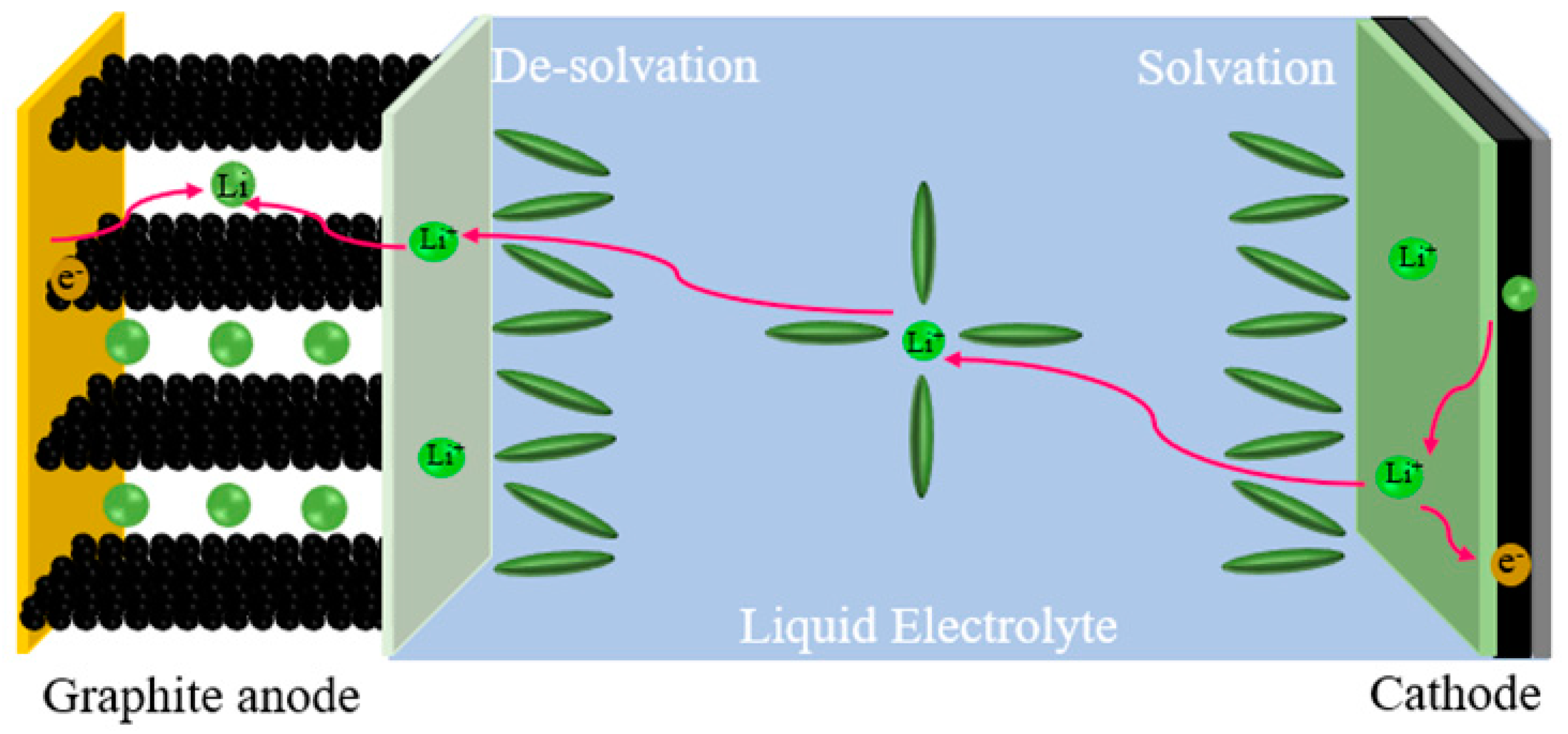
Figure 1. Schematic illustration for charging a Lithium-ion battery.
Batteries 09 00155 g001
Figure 2. CV of Li||C batteries in (a) RCE, (b) LCE, (c) HCE, (d) LHCE.
Batteries 09 00155 g002
Figure 3. (a) First CV cycle of Li||C batteries in four electrolytes. EIS analysis of Li||C batteries before (b) and after (c) three cycles of activation.
Batteries 09 00155 g003
Figure 4. Tafel curves of Li||Li batteries (a) in LHCE, (b) in the four electrolytes.
Batteries 09 00155 g004
Figure 5. Capacity-voltage curves for Li||C batteries (a) 100 long cycles in four electrolytes, (b) 1st and 100th cycles in RCE, (c) 150 long cycles in LHCE, (d) 1st and 100th cycles in LHCE.
Batteries 09 00155 g005
Figure 6. Rate performance of Li||C batteries (a) in four electrolytes, (b) capacity-voltage curves at different rates in LHCE, and (c) capacity-voltage curves at different rates in RCE. Rate performance of LFP||Li batteries (d) in two electrolytes, (e) capacity-voltage curves at different rates in LHCE, (f) capacity-voltage curves at different rates in commercial electrolytes.
Batteries 09 00155 g006
Figure 7. Thicknesses of SEI film formed under four electrolytes. SEI film morphology after CV cycling in (a) RCE, (d) LCE, (g) HCE, and (j) LHCE; SEI film morphology after AFM probe tip scraping: (b) RCE, (e) LCE, (h) HCE, and (k) LHCE; and thickness profiles of the corresponding regions: (c) RCE, (f) LCE, (i) HCE, and (l) LHCE.
Batteries 09 00155 g007
Figure 8. Optical micrograph of HOPG after 3 cycles of CV. (a) LCE, (b) LHCE.
Batteries 09 00155 g008
Figure 9. XPS analysis of graphite anode after three cycles in RCE electrolyte: (a) C 1s, (b) F 1s, (c) O 1s, (d) Li 1s.
Batteries 09 00155 g009
Figure 10. XPS analysis of graphite anode after three cycles in LHCE electrolyte: (a) C 1s, (b) F 1s, (c) N 1s, (d) O 1s, (e) S 2p, (f) Li 1s.
Batteries 09 00155 g010
Figure 11. Schematic illustration of Li+ embedded graphite layer in (a) LCE, (b) HCE, (c) LHCE.
Batteries 09 00155 g011
Table 1. The prepared electrolytes used in experiments.
NameElectrolyte Components
RCE (routine electrolyte)1 M LiPF6 EC:DMC = 1:1
LCE (low-concentration ether electrolyte)1.5 M LiFSI in DME
HCE (high-concentration electrolyte)
LHCE (localized high-concentration electrolyte)
4.5 M LiFSI in DME
1.5 M LiFSI TTE:DME = 2:1
Table 2. Interfacial film impedance values before and after the CV cycle for four electrolytes.
ElectrolyteRSEIRSEI’
RCE 291.853.9
LCE 39.28.9
HCE 199.29.8
LHCE117.47.7
Disclaimer/Publisher’s Note: The statements, opinions and data contained in all publications are solely those of the individual author(s) and contributor(s) and not of MDPI and/or the editor(s). MDPI and/or the editor(s) disclaim responsibility for any injury to people or property resulting from any ideas, methods, instructions or products referred to in the content.